extended surfaces - fins the function of finsottp.fme.vutbr.cz/vyuka/prenostepla/zebra.pdf ·...
TRANSCRIPT

EXTENDED SURFACES - FINSThe Function of Fins• Increase heat transfer rate for a fixed surface
temperature, or
• Lower surface temperature for a fixed heat transfer rate
Newton's law of cooling
(3.63))T(T aSQ sss ∞−=&
Rewrite (3.63)
s
ss aS
QTT
&+=
∞
sQ&• “Extending” Ss for a fixed Tsincreases
• “Extending” surface at fixed lowers sQ& sTBased on presentations by professor Latif M. Jiji, The City College of New York

• A surface is “extended” by adding fins • Examples of fins:
• Thin rods on the condenser in back of refrigerator.• Honeycomb surface of a car radiator.• Corrugated surface of a motorcycle engine.• Coolers of PC boards.
Types of Fins
finstraight areaconstant (a) finpin(c)
finstraight areavariable(b) finannular (d)
3.12Fig.

Fin terminology and types
• Fin base (pata žebra)• Fin tip (konec žebra)• Straight fin: Fig. 3.12 (a) and (b). • Variable cross-sectional area fin: Fig. 3.12 (b), (c) and
(d). • Spine or a pin fin: Fig. 3.12 (c).• Annular or cylindrical: Fig. 3.12 (d).
Heat Transfer and Temperature Distribution in Fins• Heat flow through a fin is
axial and lateral (2-D)x
∞Th,
δT
∞Tr
3.13 Fig.∞
Tα,

• Note temperature profile, Fig. 3.13
• Temperature distribution is 2-D
The Fin ApproximationNeglect temperature variation in the lateral direction r and assume uniform temperature at any section:
T ≈ T(x)
• Criterion for justifying this approximation:(3.64)Biot number = Bi = αδ /λ << 1
Bi < 0.1
x
∞Th,
δT
∞Tr
3.13 Fig.∞
Tα,

• Meaning of the Biot number:
resistance externalresistance internal
1/αδ/λBi ==
The Fin Heat Equation• Objective: Determine the heat transfer rate from a fin.
Need the temperature distribution• Procedure: Formulate the fin heat equation:
Conservation of energy for element dx.
• Select an origin and a coordinate axis x
• Assume Bi < 0.1: T ≈ T(x)
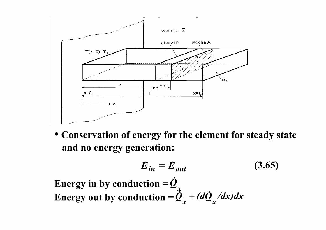
• Conservation of energy for the element for steady state and no energy generation:
(3.65)outin EE && =
Energy in by conduction = xQ&
Energy out by conduction = /dx)dxQ(dQ xx&& +

Energy out by convection = convQd &
Neglect radiation:
(a) and (b) into (3.65)
0Qddxxd
Qdconv
x =+ &&
(c)
Fourier's law and Newton’s law:
dxdTAλQx −=& (d)
(a)xQ&=
(b)convx
xout QddxdxQd
QE &&
& ++=
)(b
CsdA
cdq
xq dxdxdqq x
x +
dS=P.dx
convQd &
P

(d) and (e) into (c)
A = cross-sectional conduction area
= surface area of element through which heat isdSconvected
0Pdx)Tα(TdxdxdTλA
dxd
=−−⎥⎦⎤
⎢⎣⎡
∞ (f)
Assume: constant λ
(3.66)0)T(TλAαP
dxTd2
2=−−
∞
(e))P.dxT(TαQd conv ∞−=&
α is a surface average heat transfer coefficient

• Equation (3.66) is the heat equation for fins
0)T(TλAαP
dx
)T-(Td2
2
=−−∞
∞ (3.66)
∞−TTOr assuming constant and replacing T with
∞T

Boundary Conditions
Two B.C. are needed

Determination of Fin Heat Transfer Rate oQ&
• Conservation of energy applied to a fin at steady state:
(1) Conduction at the base: Fourier's law
(3.68)( )
0xo dxTTdλAQ =∞−
−=&
base theat conduction =fqsurface theat convection =
oQ&
• Two methods to determine oQ&

(2) Convection at the fin surface: Newton's law
(3.69)∫ −= ∞S
o P.dx]Tα[T(x)Q&
• Modify (3.69) to include heat exchange by radiation
• Introducing a new parameter fin parameter m L
λAPαmL =
Rewrite (3.66)
0)T(Tmdx
)T-(Td 22
2
=−−∞
∞ (3.70)

` • Equation (3.73) is valid for:(1) Steady state(2) Constant λ(3) No energy generation(4) No radiation(5) Bi << 1
(6) Constant fin area (7) Constant ambient temperature ∞T

Solution
Solution to (3.70) is
(3.71) mx2
mx1 eCeCTT(x) −
∞+=−
C1 and C are integration constants. They depend on:
0)T(Tmdx
)T-(Td 22
2
=−−∞
∞ (3.70)
• Location of the origin` • Direction of coordinate axis x`
• Two boundary conditions
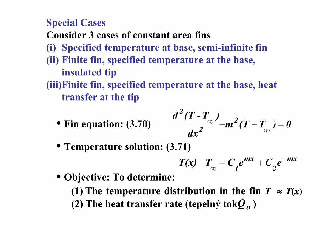
Special CasesConsider 3 cases of constant area fins(i) Specified temperature at base, semi-infinite fin(ii) Finite fin, specified temperature at the base,
insulated tip(iii)Finite fin, specified temperature at the base, heat
transfer at the tip
• Fin equation: (3.70)
• Temperature solution: (3.71)
• Objective: To determine:(1) The temperature distribution in the fin T ≈ T(x) (2) The heat transfer rate (tepelný tok ) oQ&
0)T(Tmdx
)T-(Td 22
2
=−−∞
∞
mx2
mx1 eCeCTT(x) −
∞+=−

• The base is at temperature oT• Ambient temperature is ∞T• Fin equation: (3.70)• Solution: (3.71)
• B.C. are:
Case (i): Semi-infinite fin with specified temperature at the base
(3.71) mx2
mx1 eCeCTT(x) −
∞+=−
0 xC∞Th,
∞Th,oT cA
3.16 Fig.
∞Tα,
∞Tα,
P
A
T(0) = ,To (a) ∞∞−=− TTTT(0) 0
(b) T(∞) = ,T∞ 0T)T( =−∞
∞

B.C. (b)
∴ C1 = 0 0,CC0 21 ⋅+∞⋅=
B.C. (a)
mx)exp(TTTT(x)
Θo
−=−
−=
∞
∞ (3.72)
∞−= TTC 02
mx))exp(T(TTT(x) o −−=−∞∞

• Fin heat transfer oQ& :
(3.73)
( ) )TλAm(Tdx
TTdλAQ 00xo ∞=∞ −=
−−=&
( )∞−= TTPαλAQ 0o&
Obviously, no dependence on the fin length
( )∞−= TTPαλA
Q0
o&

Case (ii): Finite length fin with specified temperature at the base and insulated tip
Same as Case (i) except the tip is insulated.
mx2
mx1 eCeCTT(x) −
∞+=−General solution:
( ) 0dx
TTdLx =
−=
∞
0=∂∂
−==
=Lx
Lx xTλSQ& cA
Cth0
oT
∞Th,x
∞Th,
3.17 Fig.
∞α,T
∞α,T
P
Tip B.C.
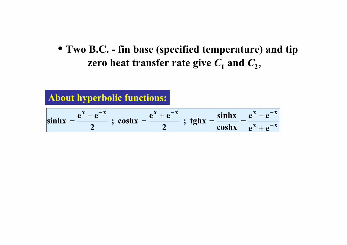
About hyperbolic functions:
xx
xxxxxx
eeee
coshxsinhxtghx ;
2eecoshx ;
2eesinhx −
−−−
+−
==+
=−
=
• Two B.C. - fin base (specified temperature) and tip zero heat transfer rate give C1 and C2,

mLxLm
TTTxTΘ
o cosh )-(cosh )(
=−−
=∞
∞Solution:
mlmL)TλAm(TQ 0o cosh
sinh∞−=&
Similarly heat transfer rate(tepelný tok):
( ))(tgh
0mL
TTPAQo =
− ∞αλ&
( )0xo dx
TTdλAQ =∞−
−=&
Tip temperature (x=L):mLTT
TTΘ LL cosh
10
=−−
≡∞
∞

Compare with the semi-infinite fin: ( )∞−= TTPαλA
Q0
o&
)(0,014. 0 ∞∞ −=− TTTTL
014,00
=−−
≡∞
∞TTTTΘ L
L

Case (iii): Finite length fin with specified temperature at the base and heattransfer at the tip
cA
Cth0
oT
∞Th,x
∞Th,
3.17 Fig.
∞α,T
∞α,T
P
∞α,T
[ ] ( ) [ ]( ) mLmmL
xLmmxLmTT
TxTΘL
Lsinh/cosh
)(sinh/)(cosh)(0 λα
λα+
−+−=
−−
≡∞
∞

Corrected Length Lc
• Fins with insulated tips have simpler solutions than fins with convection at the tip
• Simplified model: Assume insulated tip and compensate by increasing the length by ΔLc
• The corrected length Lc is cc LLL Δ+=
• The correction increment ΔLc = t/2 fin half width
0,0625λαt
≤• Error negligible if

Fin Effectiveness (efektivnost) εfFin Efficiency (účinnost) ηf
Fin performance is described by two parameters:
Fin Effectiveness εfenhancement due to fin addition.
: Measures heat transfer
Defined as
A
Ratio of heat transfered by the fin and heat transferedfrom the original area A of the fin ( )∞−= TTαAQ obase
( ) base
o
o
of Q
QTTαA
Qε&
&&=
−=
∞mlmL)TλAm(TQ 0o cosh
sinh∞−=&

εf must be >2, otherwise don’t use the fin.
( )( ) αA
λPTTαA
TTλAαPεo
of =
−−
=∞
∞
For a semi-infinite fin:
How to increase fin effectivness:• high conductivity material λ• high perimeter to area ratio P/A – thin fin and close
each to other• use fin where heat transfer coefficient α is low

fS = total fin surface area
Introduce the above into (3.89)
Fin Efficiency fηwith the maximum heat that the fin can transfer. Defined as
: Compares heat transfer from a fin
(3.89) o,max
of Q
Qη&
&=
the base temperature= heat transfer from fin if its entire surface is ato,maxQ&
( )∞−= TTαSQ ofo,max&
(3.90) ( )∞−
=TTαS
Qηof
of
&

Total Fin Efficiency (účinnost) ηtot
( )∞−==
TTαSQ
QQη
oTOT
TOT
TOT,max
TOTTOT
&
&
&
TOTQ& Total heat transfer rate from the total finned surface of an actual finned surface
When the entire finned surface is at the base temperature
TOT,maxQ&
TOTS Total finned surface (including surface between individual fins) ofTOT SSS +=
fS
oS
( ) ( )∞∞ −+−= TTSTTSQ oooffTOT αηα& (3.91)

( ) ( )∞−⎥⎦
⎤⎢⎣
⎡−−= TT
SS
SQ ofTOT
fTOTTOT ηα 11&
After some rearrangement of (3.91)
( )fTOT
fTOT S
Sηη −−= 11
Taking the definition of the total efficiency
( )( )∞
∞−=⇒
−= TTηαSQ
TTαSQη oTOTTOTTOT
oTOT
TOTTOT &
&
we come to the definition of a total efficiency

Practical procedure how to calculate heat transfer rate from a finned surface
fS
oS
ofTOT SSS +=
1. Specify efficiency of an individual fin ηf using graphs
2. Calculate total surface of fins and “free” space between fins
3. Calculate total efficiencyTOη ( )f
TOT
fTOT S
Sηη −−= 11
4. Calculate maximum heat transfer rate )T(TαSQ oTOTTOT,max ∞−=&
5. Calculate actual heat transfer rate
TOT,maxTOTTOT QηQ && =

Fin efficiency for three types of straight fins
Graphs of fin efficiency

Fin efficiency for annular fins
Graphs of fin efficiency