extended functionality and validation of sulsim sulfur recovery in … · 2018-04-06 · modeling...
TRANSCRIPT

Extended Functionality and Validation of Sulsim™ Sulfur Recovery in Aspen HYSYS®
Chad Mondor, Product Management, Aspen Technology, Inc.Jennifer Dyment, Product Marketing, Aspen Technology, Inc.Ben Fischer, R&D, Aspen Technology, Inc.
White Paper

Executive Summary 3
Introduction 4
Managing H2S in Gas Plants and Refineries 4
Sulfur Recovery Process 5
A Need for Simulation 6
Challenges in the SRU and Plant Wide 6
Rigorous Sulfur Recovery Modeling 7
Implementation of Sulsim Sulfur Recovery in Aspen HYSYS 7
Optimizing the Full Gas Plant with Aspen HYSYS and aspenONE® Engineering 8
Sulfur Component Breakthrough Prediction 8
Temperature Prediction 9
Sulfur Conversion Efficiency 9
New Innovations in Sulsim Sulfur Recovery in Aspen HYSYS 10
New Furnace Empirical Models 11
Catalytic Converter Titania Model 12
New Selective Oxidation Converter Model 12
Incinerator Component Breakthrough Model 13
Conclusion 14
Additional Resources 15
References 15
Table of Contents
2

Executive SummarySulfur is a toxic impurity found in all crude oil, as well as conventional and unconventional natural gas sources. Sulfur must be removed in various refining and gas processes to meet product and environmental standards. The Modified-Claus process of converting hydrogen sulfide, sulfur dioxide and other sulfur-containing gases to less toxic elemental sulfur is complex and is often an expense to the gas processing facility or refinery. Modeling the sulfur recovery unit (SRU), in a simulator such as Aspen HYSYS®, can empower engineers to make better decisions in operating the SRU by reducing costs and avoiding penalties and turndown due to not meeting flare specifications.
Sulsim, created by Sulphur Experts, was acquired by Aspen Technology in April 2014. All Sulsim functionality has been fully incorporated into Aspen HYSYS V9. The results generated from Sulsim™ Sulfur Recovery in Aspen HYSYS were compared to those generated from Sulsim by Sulphur Experts to ensure consistency. There are a few notable exceptions due to improved correlations and functionality in Aspen HYSYS, as detailed in the Aspen HYSYS in-product help. A selection of these validation results are presented in this paper.
In addition to supporting the full set of functionality available in Sulsim by Sulphur Experts, Sulsim Sulfur Recovery in Aspen HYSYS builds upon existing functionality to include new models and features. This new functionality, including new furnace empirical correlations, a new titania catalyst model, a new selective oxidation converter model and a new kinetic incinerator model is included in Aspen HYSYS V9. The results of these models were validated against experimental and plant data in collaboration with Sulphur Experts. A subset of validation data covering these new models is also provided in this paper.
This white paper covers the following topics:
▪ Sulfur recovery process
▪ Value of process simulation for the SRU
▪ Implementation of Sulsim Sulfur Recovery in Aspen HYSYS
▪ Validation results for Sulphur Experts’ Sulsim vs. Aspen HYSYS
▪ Validation results for new functionality included within Sulsim Sulfur Recovery in Aspen HYSYS
3

IntroductionManaging H2S in Gas Plants and RefineriesSulfur is present in crude oil, shale oil and in conventional and unconventional natural gases. Hydrogen sulfide (H2S) is present in natural gas and is created in refining processes. H2S presents risks to people, the environment and downstream equipment. For these reasons, H2S must be removed from sales gas and treated in the gas plant to meet tail gas requirements. Additionally, H2S is an inert gas and thereby decreases the heating value of sales gas.
H2S is typically removed from natural gas through the amine treating process in the regenerator overhead. This off-gas stream is typically directed to the SRU and uses the Modified-Claus process to convert H2S into elemental sulfur, which is less toxic and can be sold for use in other industries. As of 2016, more than 90% of the elemental sulfur produced in the U.S. had been recovered from refineries and midstream gas plants. The total annual world production of sulfur, as of 2015, was 70 million metric tons. The principal use of sulfur is in the production of sulfuric acid, and is used in a number of specialty applications, although the major end product is for use in fertilizer.
Engineers must configure a sulfur recovery unit to meet the specific needs of their plant feeds and operations. The configuration process of furnaces, condensers, heat exchangers, catalytic converters, and tail gas treating units needs to be flexible to ensure reliability with changing feed conditions. To accurately predict performance, engineers must track and simulate sulfur conversion throughout the unit, with attentiveness to conversion and removal efficiencies of each step. For maximum prediction accuracy, engineers must utilize a process simulator with models validated over a wide range of commercial operations and conditions, and calibrate against plant data.
4

Sulfur Recovery Process
The sulfur recovery process employs a Modified-Claus reaction that captures elemental sulfur from hydrogen sulfide, carbonyl sulfide, carbon disulfide, sulfur dioxide and other sulfur-containing species in a series of thermal and chemical reactions. Typically, acid gases from the acid gas treating process and other refinery off-gas streams, such as sour water strippers, are combined and sent to a reaction furnace with air at a high temperature. Reactions take place in about two seconds at 1000-1400°C, with the goal of converting one third of the total H2S in the inlet to SO2 at the outlet. Following heat recovery, elemental sulfur produced in the furnace is drawn out of the system using a low temperature condenser at about 130°C. The remaining gaseous effluent is sent through several catalytic sections in a series which continue to convert the remaining SO2 and H2S to elemental sulfur and water. Typically, a cumulative sulfur recovery of > 98% is targeted in refining and midstream applications. The gaseous effluent from the last catalytic stage condenser is low in sulfur-containing compounds, but may require some additional treating to meet flare gas specifications. This gas is sent to tail gas treating processing, which can contain unit operations such as a hydrogenation bed, reducing gas generator, quench tower, amine absorber, incinerator, and flare. In short, the sulfur recovery process is a key enabler to process sour feeds and meet emissions specifications, while producing elemental sulfur for sales.
Figure 1: Sulfur recovery unit with a 2 + 1 selective oxidation catalytic section.
5

A Need for SimulationChallenges in the SRU and Plant WideThe goal of the sulfur recovery process is to remove sulfur from process streams at an optimal recovery efficiency, with attention to tail gas specifications and costs. The SRU is part of a larger process, whether at a refinery or a gas processing facility, and the performance of process units before the SRU can affect the SRU.
The SRU can sometimes be a bottleneck in refining in terms of limiting the amount of sulfur that can be accommodated in crude oil and unconventional feedstocks while meeting flare specifications. By maximizing sulfur recovery, refiners may be able to accommodate more sour crudes in the slate for increased margins. Changing feed conditions can cause variability in operations and changes may present additional operational costs that need to be considered when switching feedstocks.
The sulfur recovery process involves many energy-intensive steps, where process streams must be heated and cooled to achieve conversion and sulfur removal. Engineers can minimize OPEX in existing plants by identifying optimal temperatures for operation.
In the design of new plants or plant expansions, engineers need to consider multiple plant configurations to meet sulfur recovery targets for a given operating window at a minimum capital investment, while also ensuring that the design is flexible enough for the needs of the plant.
6

Rigorous Sulfur Recovery ModelingSulsim Sulfur Recovery can be used to meet regulations and avoid penalties. Sulsim has been used in the industry for decades, and has been proven to be one of the most accurate simulators of this process. Users can take advantage of Sulsim Sulfur Recovery and gain confidence when making guarantees on specifications or meeting targets in operation. Sulsim Sulfur Recovery can be used to operate reliably and process sour feedstocks.
Sulsim Sulfur Recovery can pre-emptively predict sulfur recovery unit performance, ensuring reliable operation and reducing the number of upsets.
Implementation of Sulsim Sulfur Recovery in Aspen HYSYSThe functionality that has been available for decades as part of the standalone Sulsim has been completely incorporated into Aspen HYSYS V9. AspenTech and Sulphur Experts have independently validated and verified that all pre-existing functionality works as designed in the Aspen HYSYS environment.
In Aspen HYSYS, the Sulsim property package, sub-flowsheet environment and unit operations can be used to accurately simulate all major commercial process configurations for the Modified-Claus process with over 30 unit operations.
Standalone Sulsim has been fully integrated into Aspen HYSYS by implementation of:
▪ A specialized sulfur recovery sub-flowsheet environment, as shown in Figures 1 and 2.
▪ A dedicated Sulsim Sulfur Recovery property package. (See Figure 3 for components that are required and supported.)
▪ A specialized unit operations palette, including all previously available Sulsim unit operations, as well as some new operations introduced in this release.
▪ A Sulsim-to-HYSYS case converter for easy customer migration.
Aspen Technology and Sulphur Experts worked extensively to ensure that the results were sufficiently equivalent, and tested hundreds of cases, resulting in released software that does not contain any unexpected differences in the results between the two simulators. Sulsim Sulfur Recovery in Aspen HYSYS includes improvements to the underlying models that are available in Sulphur Experts’ Sulsim. Some of these improvements cause expected known differences in simulation results, as noted in the in-product help.
7

Optimizing the Full Gas Plant with Aspen HYSYS and aspenONE® EngineeringTime and effort can be lost in the transfer of data between simulation tools. Sulsim Sulfur Recovery is a specialized tool within a larger simulator, enabling engineers to consider the full process and the interconnections between units.
With demonstrated accuracy of results and continued use by top oil and gas organizations worldwide for the last 30 years, Aspen HYSYS is a trusted simulation tool. Aspen HYSYS offers property packages specifically designed and tested for difficult-to-model processes such as acid gas removal and dehydration. With market-leading accuracy, you can model and optimize the whole gas process in one environment without having to compromise by using separate simulation tools that require data transfer.
aspenONE Engineering is a trusted modeling solution that allows users to model different parts of the gas plant, including acid gas removal, sulfur removal, dehydration, NGL fractionation, liquefaction, compressor operability, and more. Aspen HYSYS, part of the aspenONE Engineering suite, is powerful - allowing users to consider equipment sizing, costs, energy networks and safety systems right in the process model.
Sulfur Component Breakthrough PredictionAs part of the validation work between the two simulators, component breakthroughs following unit operations such as the reaction furnace, waste heat exchangers, catalytic converts, etc. were compared. In Figure 2 shown top right, you’ll find a small subset of that data for the furnace and catalytic converter which illustrates the methodology used in the validation. Results from Sulphur Experts’ Sulsim are plotted on the x-axis and the results from Aspen HYSYS are plotted on the y-axis. The results in almost all of the commercial cases tested were nearly identical.
Figure 3: Results from Sulphur Experts’ Sulsim compared to Aspen HYSYS for catalytic converter component breakthrough.
Figure 2: Results from Sulphur Experts’ Sulsim compared to Aspen HYSYS for reaction furnace component breakthrough.
8

Temperature PredictionAs part of the validation work between the two simulators, Aspen Technology and Sulphur Experts compared the outlet temperature of key unit operations such as the reaction furnace, catalytic converters, HBED, etc. Figure 4 right shows a subset of that data. The results from Sulphur Experts’ Sulsim are plotted on the x-axis and the results from Aspen HYSYS are plotted on the y-axis. The results were shown to be nearly identical in the majority of cases. In some cases, particularly when recycling sulfur from the tail gas section to the reaction furnace, Aspen HYSYS results were slightly different due to improvements in empirical models and tighter solver tolerances.These differences are elaborated upon in the Aspen HYSYS in-product help.
Sulfur Conversion EfficiencySulfur conversion efficiency is an important metric to optimize the SRU and to understand the effect of operational changes. Aspen Technology and Sulphur Experts compared the sulfur conversion efficiency in each stage of the SRU between the two simulators. Figure 5 right is a small subset of that data for the purpose of illustrating the validation methodology. The results from Sulphur Experts’ Sulsim are plotted on the x-axis and the results from Aspen HYSYS are plotted on the y-axis. Some differences were observed between Sulphur Experts’ Sulsim and Sulsim Sulfur Recovery in Aspen HYSYS. However, these differences were expected as part of the model improvements made in Aspen HYSYS V9. Please refer to the contacts listed at the end of this paper if you do not have access to Aspen HYSYS V9. In cases where significant differences were observed, results were compared against the original plant data and the Aspen HYSYS results were generally found to be more accurate.
Figure 4: Results from Sulphur Experts’ Sulsim compared to Aspen HYSYS for outlet temperature prediction of key unit operations.
Figure 5: Results from Sulphur Experts’ Sulsim compared to Aspen HYSYS for sulfur conversion efficiency across the thermal and catalytic stages of the SRU.
9

New Innovations in Sulsim Sulfur Recovery in Aspen HYSYSAll previously available functionality in Sulphur Experts’ Sulsim is made available in Sulsim Sulfur Recovery in Aspen HYSYS V9. In addition to pre-existing functionality, Aspen Technology and Sulphur Experts have worked together to include a new suite of models and capabilities that cover a wider range of operating conditions and equipment configurations.
▪ The Sulfur Recovery (Sulsim) property package contains extended components S1 through S8, with full details of these sulfur species concentrations reported to the user in the simulation environment.
▪ Five new empirical reaction furnace models have been included in this release, extending the total number to nine models. These models were developed from 769 unique plant data sets and have been validated to be more accurate predictors of furnace operation compared to legacy models.
▪ A new incinerator model with kinetic correlations is now available, which predicts breakthroughs of key sulfur species to the flare.
▪ The catalytic converter unit operations now include a model for simulating titania catalyst (including mixed bed), as well as alumina catalyst.
▪ A new model has been developed for the selective oxidation converter, which now predicts conversion.
▪ A new, simplified SO2 absorber unit operation is now included.
In this section, we will discuss these new features and selected examples of the underlying validation work done to ensure accuracy.
10

New Furnace Empirical ModelsWith Aspen HYSYS V9, five new furnace models have been developed from 769 unique plant data sets. Aspen Technology and Sulphur Experts regressed the data to create predictive models for conversion, CO, COS, CS2, H2, etc. The new empirical models include support for the following feeds and configurations:
▪ Straight Through Amine Acid Gas
– A newly recommended model for all acid gas feeds in which all of the acid gas is processed through the main burner. Typically, this arrangement does not accommodate feeds that are high in ammonia (NH3), oxygen enrichment or fuel gas co-firing.
▪ Sour Water Stripper (SWS) Acid Gas
– A newly recommended model used for furnace feeds that contains effluent from sour-water stripping processes, i.e. significant amounts of NH3 up to 17 mol%.
▪ Split Flow With Lean Acid Gas
– A newly recommended model for furnace arrangements with an acid gas bypass around the furnace is used to increase the furnace temperature for very lean acid gas feeds. Typically, this arrangement does not include significant NH3 in feed, oxygen enrichment or fuel gas co-firing.
▪ Oxygen Enrichment For All Acid Gas Feeds
– A newly recommended model for any acid gas feed that uses oxygen-enriched air streams. This model accommodates a wide range of acid gas streams including those that are rich and lean in H2S, as well as feeds containing NH3.
▪ Co-Firing Amine Acid Gas
– A newly recommended model to use for any acid gas feed for when fuel gas is also being used as feed to the main burner to increase furnace temperature. This includes increasing furnace temperature of a lean acid gas for flame stabilization, BTEX destruction or NH3 destruction.
Extensive validation was completed by Aspen Technology and Sulphur Experts. Since the original furnace models were released with Sulsim 5, twice as many commercial data sets were regressed for the new models available in Aspen HYSYS V9, resulting in more accurate and more widely applicable furnace models.
11

Catalytic Converter Titania ModelA new titania catalyst model was developed for Sulsim Sulfur Recovery in Aspen HYSYS V9. Extensive regression and validation work was completed for the development of the titania catalyst model to ensure that the results were in line with commercial expectations. The titania catalyst model was determined to be valid for mixed catalyst beds if the titania volume was at least 25% of the total catalyst. The titania catalyst model also predicts whether equilibrium conditions are achieved based on the catalyst volume or space velocity. For this reason, the titania catalyst model requires the user to input either the catalyst volume or space velocity to determine whether equilibrium was reached and if it accurately predicted the breakthrough of components such as COS and CS2.
Extensive regression and validation work was completed during the development of the new model. For example, a COS conversion curve vs. reactor temperature was developed for equilibrium and non-equilibrium conditions, as shown below.
New Selective Oxidation Converter ModelIn Sulphur Experts’ Sulsim, a user was required to input a conversion efficiency when using the selective oxidation converter model. The selective oxidation converter unit operation can be used to simulate catalytic converters that leverage air or O2 for selective oxidation of sulfur species, such as with the Jacobs SUPERCLAUS® process. In Aspen HYSYS V9, a new “2016” selective oxidation converter model option has been added, which predicts the overall conversion efficiency based on commercial experience. A comparison of the predicted vs. actual conversion efficiency using the “2016” selective oxidation converter model is shown right in Figure 7 for a subset of plant data sets.
Figure 6: COS conversion vs. temperature for the titania catalyst model at equilibrium and non-equilibrium conditions..
Figure 7: Comparison of predicted vs. actual conversion efficiency using the “2016” selective oxidation converter model in Aspen HYSYS.
12
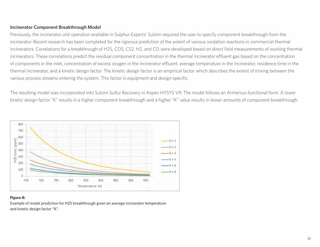
Incinerator Component Breakthrough ModelPreviously, the incinerator unit operation available in Sulphur Experts’ Sulsim required the user to specify component breakthrough from the incinerator. Recent research has been completed for the rigorous prediction of the extent of various oxidation reactions in commercial thermal incinerators. Correlations for a breakthrough of H2S, COS, CS2, H2, and CO were developed based on direct field measurements of working thermal incinerators. These correlations predict the residual component concentration in the thermal incinerator effluent gas based on the concentration of components in the inlet, concentration of excess oxygen in the incinerator effluent, average temperature in the incinerator, residence time in the thermal incinerator, and a kinetic design factor. The kinetic design factor is an empirical factor which describes the extent of mixing between the various process streams entering the system. This factor is equipment and design specific.
The resulting model was incorporated into Sulsim Sulfur Recovery in Aspen HYSYS V9. The model follows an Arrhenius functional form. A lower kinetic design factor “K” results in a higher component breakthrough and a higher “K” value results in lesser amounts of component breakthrough.
Figure 8: Example of model prediction for H2S breakthrough given an average incinerator temperature and kinetic design factor “K”.
13

ConclusionThe improvements made in Sulsim Sulfur Recovery in Aspen HYSYS V9 increase the accuracy of modeling the Modified-Claus process and extend the applicability to a wider range of feed conditions, unit operations and catalyst types. Sulsim Sulfur Recovery is used widely in the industry to ensure sulfur recovery targets are met at minimal cost and that maximum flexibility is given to both operations and process design.
For the first time in Aspen HYSYS V9, users can optimize all major gas plant processes. Acid Gas Cleaning property packages can be used to simulate the acid gas and tail gas treating sections of the plant using rigorous rate-based technology. This functionality has been expanded further in Aspen HYSYS V9 with new liquid-liquid treating capabilities, additional supported components and solvents and Column Hydraulics capabilities for equipment-based modeling. The Aspen HYSYS glycol property package can be used to model the dehydration process by accurately predicting the extent of glycol dehydration of the sales gas. The Peng Robinson property packages, and other layered functionality such as the mercury-partitioning utility, can be used in Aspen HYSYS to simulate the removal of inerts such as N2 and He, as well as other contaminants such as Hg. Aspen HYSYS and Aspen Exchanger Design and Rating (Aspen EDR) can also be used to simulate LNG compression and regasification. Finally, Aspen Flare System Analyzer™ can simulate flaring with the goal of meeting environmental regulations.
Layered functionality from other AspenTech products are also available for use in areas of the Aspen HYSYS gas plant flowsheet, such as Aspen Simulation Workbook™ (ASW), Aspen Capital Cost Estimator™ (ACCE), Aspen Energy Analyzer™, and other safety environment functionality, such as BLOWDOWN™ Technology and relief valve sizing.
Thank you to Bruce Klint and Sulphur Experts for their assistance with integrating Sulsim into Aspen HYSYS and validating the new features available with Sulsim. For questions about this paper, please contact Jennifer at [email protected].
14
Additional Resources
Jump Start Guide: Sulsim™ Sulfur Recovery in Aspen HYSYS®
Video: Predict Sulfur Emissions and Minimize Costs with Sulsim Sulfur Recovery in Aspen HYSYS
Deep Dive Video: Learn About Sulsim Sulfur Recovery in Aspen HYSYS
Video: Make Confident Decisions in the Gas Plant with Aspen HYSYS
Validation White Paper: Acid Gas Cleaning Using Amine Solvents: Validation with Experimental and Plant Data
Validation White Paper: Acid Gas Cleaning Using DEPG Physical Solvents: Validation with Experimental and Plant Data
Validation White Paper: Acid Gas Cleaning in Aspen HYSYS for Liquid Hydrocarbons
Computer-Based Training: Sulsim Sulfur Recovery in Aspen HYSYS
References1. Apodaca, Lori, 2013 Minerals Yearbook Sulfur (advance release), United States Geological Services, August 2015, 74.2.
http://minerals.usgs.gov/minerals/pubs/commodity/sulfur/myb1-2013-sulfu.pdf
15

AspenTech is a leading software supplier for optimizing asset performance. Our products thrive in complex, industrial environments where it is critical to optimize the asset design, operation and maintenance lifecycle. AspenTech uniquely combines decades of process modeling expertise with machine learning. Our purpose-built software platform automates knowledge work and builds sustainable competitive advantage by delivering high returns over the entire asset lifecycle. As a result, companies in capital-intensive industries can maximize uptime and push the limits of performance, running their assets faster, safer, longer and greener.
www.aspentech.com
© 2018 Aspen Technology, Inc. AspenTech®, aspenONE®, the Aspen leaf logo, the aspenONE logo
and OPTIMIZE are trademarks of Aspen Technology, Inc. All rights reserved. AT-03966-0318