export transmission cables for offshore renewable
TRANSCRIPT
Export transmission cables for offshore renewable installations
PrinciPles of cable routeing anD sPacing
Export transmission cables for offshore renewable installations – Principles of cable routeing and spacing • 2 www.thecrownestate.co.uk
© Crown Copyright 2012 Published by The Crown Estate. This report is available on The Crown Estate website at: www.thecrownestate.co.uk
Dissemination statementThis publication (excluding the logos) may be re-used free of charge in any format or medium. It may only be re-used accurately and not in a misleading context. The material must be acknowledged as Crown Estate copyright and use of it must give the title of the source publication. Where third party copyright material has been identified, further use of that material requires permission from the copyright holders concerned.
DisclaimerThe opinions expressed in this report are entirely those of the authors and do not necessarily reflect the view of The Crown Estate, and The Crown Estate is not liable for the accuracy of the information provided or responsible for any use of the content.
Suggested citationRed Penguin Associates Ltd, 2012 ‘Export transmission cables for offshore renewable installations – Principles for cable routeing and spacing’. The Crown Estate.
Revision 1.0 /30-08-2012
Images featured in this report are courtesy of Red Penguin Associates Ltd, The Crown Estate, Offshore Marine Management, EMU, Deepocean, Seabreeze, Fotolia, Thinkstock.
by:
Cams Hall Fareham Hampshire PO16 8AB England Tel: +44 1329 227 429
to:
16 New Burlington Place London WS1 2HX Tel: +44 20 7851 5080
Disclaimer The contents of this study are intended for information only. They do not constitute advice, are not exhaustive and do not indicate any specific course of action. Detailed professional advice should be obtained before taking or refraining from taking action in relation to any of the contents of this study.
This study endeavours to reflect best industry practice. For the avoidance of doubt no legal liability shall attach to any recommendation and/or statement herein contained.
Neither the authors nor The Crown Estate accept any liability for any errors in this document or for any consequences resulting from its use as a reference document. Nothing in this document should be viewed as relieving anyone from the rights and obligations of seabed users under law, including but not limited to the United Nations Convention of the Law of the Sea (“UNCLOS”).
NB: This document may be subject to periodic review and users are cautioned to obtain the latest issue.
© R
edPe
ngui
n
Export transmission cables for offshore renewable installations – Principles of cable routeing and spacing • 3 www.thecrownestate.co.uk
Contents

Export transmission cables for offshore renewable installations – Principles of cable routeing and spacing • 4 www.thecrownestate.co.uk
Acknowledgements
this report was prepared by red Penguin associated ltd, the principal contributors from red Penguin being: Chris Sturgeon Danny Wilson Iain Murdoch Colin Rayman Steve Jones Colin Campbell
the authors also wish to extend grateful acknowledgement to the following people and organisations for their commitment and contribution to this document:
the client steering group (from the following): Gert Hemmingsen The Crown Estate Jack Steven The Crown Estate Richard Clay The Crown EstateSteve Holden Global Marine Systems Ltd/Subsea
Cables UKKevin Todd Global Marine Systems Energy Ltd/
Subsea Cables UKRyan Throw Forewind Hannah Evans Ofgem Marianne Anton Ofgem Kate Kendall Ofgem Bea Simancas Scottish Power/EAOW Sean Kelly Transmission Capital Jorge Alonso Coto EDPR/MORL Nicola Barberis Negra DONG Energy Stuart Dawson Mainstream/SMartWind Gavin Greene Scottish Power/EAOW
the crown estate:Gert Hemmingsen (Project Manager)
The objectiveThis report was commissioned by The Crown Estate and developed under the guidance of the Steering Group to act as a point of reference to provide The Crown Estate with general criteria for assessing the developers’ proposals
in line with best practice. The report aims to provide the reader with a technical, environmental and commercial overview of the effects of routeing transmission cables in relative close proximity. Whilst directed primarily at developers, it is also hoped the investment, insurance, OFTO and regulatory communities will find it of value in appreciating matters affecting the secure routeing and the spacing between transmission cables.
© O
ffsho
re M
arin
e M
anag
emen
t

Export transmission cables for offshore renewable installations – Principles of cable routeing and spacing • 5 www.thecrownestate.co.uk
Within the United Kingdom EEZ the development of offshore wind farms is a core element in the large scale production of renewable energy. With the Round 1 and Round 2 developments on line or close to completion, the industry is set to see significant increase in capacity over the next 12 years with the potential development of round 3 zones.
The continued growth of offshore power generation will give rise to a major expansion of the offshore transmission network linking the offshore generation with the onshore grid. Developers and transmission operators will find themselves competing for cable routeing and access rights in already congested coastal and offshore areas.
There are concerns, both within the renewable industry and across a range of other marine activities that the large expansion of the transmission network will interact and possibly conflict with other commercial enterprises.
The Crown Estate has been at the forefront in establishing the offshore renewable industry, especially against the background of tough binding renewable energy targets. Being mindful of its responsibility to maintain a secure and positive environment for the development of all marine activities, it proposed the undertaking of this study.
In March 2012 Red Penguin Associates was commissioned by The Crown Estate to conduct a desktop study and identify, review and assess the factors affecting the routeing and spacing of transmission cables. The findings, conclusions
and recommendations from the study form the basis of this report.
In association with The Crown Estate, representatives from the offshore renewable energy sector, owners, developers, operators, installers and maintenance providers were invited to participate in a Steering Group with the purpose of guiding and supervising Red Penguin Associates in the management of the study.
The study aims to balance the interests of offshore developers in their quest to minimise the cost of renewable energy, whilst ensuring deliverability with acceptable risks, against the interests of existing seabed users and other future commercial activities.
The principle objectives of the study are:• To provide The Crown Estate with general criteria for
assessing developers’ cable spacing proposals in line with best practice and the appropriate due diligence.
• To publish the study report as a point of reference, which having been directed by the Steering Group, achieves the endorsement of cross-industry representation.
Originally the study also aimed to provide the basis for a guidance note designed to assist developers in planning offshore renewable wind projects. After discussion within the Steering Group a decision was made not to pursue this option beyond the publication of the report.
In the course of investigation the study has identified a number of key issues, which will have a defining influence
on the planning of transmission projects and these can be categorised as follows:• Route design and development• The considerations of Security and Quality of Supply
Standard (SQSS)• The effects of electromagnetic fields on navigation
and the ecology• Installation, operation and maintenance of existing
and future transmission cables.
Route design and early developmentThe principles of route design and route development for submarine cables are well established.
A successful route design requires extensive research and careful planning and the developer will use data from a number of disparate sources to draw up a constraint map documenting environmental concerns and restrictions that might conflict with the potential cable route.
Constraint mapping and risk analysis should be augmented by applied installation and engineering knowledge to obtain the optimum route. Addressing the diverse issues the route design will consider the key objectives of:• Achieving acceptable risk levels for system reliability• Safeguarding system supply through transmission redundancy• Achieving cost efficiencies• Managing interactions and conflicts with other seabed users.
security of quality and supply standardThe National Electricity Transmission System Security and Quality of Supply Standard (NETS SQSS) sets out
Executive summary
Export transmission cables for offshore renewable installations – Principles of cable routeing and spacing • 6 www.thecrownestate.co.uk
a coordinated set of criteria and methodologies that Transmission Licensees shall use in the planning and operation of the National Electricity Transmission System.
The criterion presented in the NETS SQSS represents the minimum requirements for the planning and operation of the National Electricity Transmission System.
Of major concern to all stakeholders is the probability of multiple cable faults from a single event; the most significant risk of which is considered to be the inadvertent release of a ship’s anchor whilst the vessel is underway. In a few recent incidences a number of telecommunication cables have been identified as being damaged over a wide area in this manner.
Whilst such instances are rare, the advent of AIS (Automatic Identification System) has shown that cable damage caused by vessels dragging their anchors when underway is a more common cause than previously believed.
With the significant increase in output from future offshore generation the technical impact of multiple cable hits will have serious consequences, potentially resulting in a Major System Fault¹. An overriding consideration will
be the requirements of the SQSS criteria, where any amount of risk of major failure, however small, could be unacceptable.
The International Cable Protection Committee (ICPC) has been proactive in highlighting the increasing trend of cable damage in this manner and has lobbied Protection and Indemnity Clubs to communicate with shipping companies in the hope that they will pay attention to their insurers. Further action is required at a higher governmental level and the potential for serious consequences to both the UK transmission network and the international network of telecommunications cables, should be brought to the attention of the International Maritime Organisation (IMO).
The study of AIS and other data should be assessed in the planning stages to better qualify the risks associated with vessels dragging their anchors whilst underway. However unlikely such a multiple fault event might be, it is apparent that if installed redundancy is not a viable option the cable spacing will need to be sufficient to avoid such an eventuality. To what extent will need careful assessment, taking into account the density and type of shipping, seabed conditions, environmental conditions and the proposed cable burial or other protection measures.
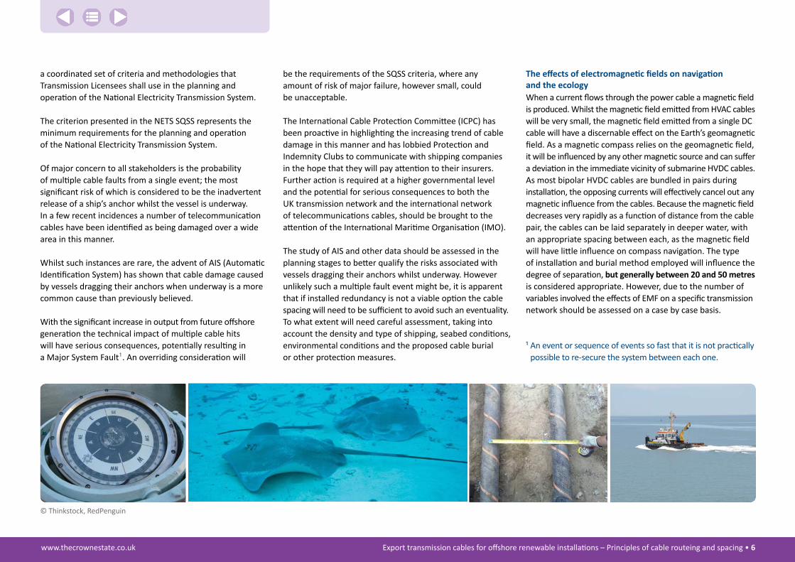
The effects of electromagnetic fields on navigation and the ecologyWhen a current flows through the power cable a magnetic field is produced. Whilst the magnetic field emitted from HVAC cables will be very small, the magnetic field emitted from a single DC cable will have a discernable effect on the Earth’s geomagnetic field. As a magnetic compass relies on the geomagnetic field, it will be influenced by any other magnetic source and can suffer a deviation in the immediate vicinity of submarine HVDC cables. As most bipolar HVDC cables are bundled in pairs during installation, the opposing currents will effectively cancel out any magnetic influence from the cables. Because the magnetic field decreases very rapidly as a function of distance from the cable pair, the cables can be laid separately in deeper water, with an appropriate spacing between each, as the magnetic field will have little influence on compass navigation. The type of installation and burial method employed will influence the degree of separation, but generally between 20 and 50 metres is considered appropriate. However, due to the number of variables involved the effects of EMF on a specific transmission network should be assessed on a case by case basis.
¹ �An event or sequence of events so fast that it is not practically possible to re-secure the system between each one.
© Thinkstock, RedPenguin

Export transmission cables for offshore renewable installations – Principles of cable routeing and spacing • 7 www.thecrownestate.co.uk
It is important that all stakeholders reach agreement on mutually acceptable spacing between pairs of HVDC cables or single HVAC cables without restraining the investment and expansion of offshore renewable energy or compromising the development of other commercial enterprises.
Optimum spacing will therefore aim to meet the objectives of:• Appropriate spacing to minimise the risk of multiple
cable hits from anchors inadvertently released with the vessel underway
• Appropriate spacing to minimise the risks to existing cables
during subsequent cable installation or maintenance• Minimising the effects of induced EMF on navigation
and the ecology• Avoiding interaction between transmission cables
therefore avoiding or minimising the need for crossing and/or proximity agreements.
Due to the considerable variation in local issues and circumstances, the spacing between cables should be considered on a case-by-case basis and attention is drawn to the worked examples and the proximity tables in Section 2, used in conjunction with AIS data, constraint mapping and a site specific risk assessment.
Optimum spacing between transmission cables
Whilst there is some suggestion that both the electrical and magnetic fields have an undesirable effect on marine species, there is only sparse evidence to the fact with conflicting conclusions from various research groups. The scientific understanding of the consequences to marine species is only slowly being identified and more research is needed before a definitive conclusion can be realised. Until the ecologists form a definitive opinion the bundling of cables is often the best approach due to consenting delays associated with the perceived impact of EMF on certain marine species.
Installation, operation and maintenance of existing and future transmission cables The installation of cables in close proximity to any existing cables will present an obvious hazard and the developer is advised to consider the limitations of current cable installation techniques, procedures and equipment when advocating a specific cable separation.
As noted above, bipolar HVDC cables can be installed as a bundled pair or individually in deeper water, subject to the necessary consents on the ecology front. Here the magnetic field will have minimal influence on magnetic compass navigation. As each cable will be installed separately, the spacing between the two cables will greatly depend on the footprint of any installation or burial equipment.
Similarly the developer is advised to consider the repair and maintenance strategy of any adjacent cables and in particular the risks associated with the fault location, de-burial, recovery, repair and deployment of the repair bight on the seabed. In some instances it may be acceptable to deploy the repair bight over an adjacent cable, but the associated commercial and technical risks will have to be fully appreciated.
© R
edPe
ngui
n

Export transmission cables for offshore renewable installations – Principles of cable routeing and spacing • 8 www.thecrownestate.co.uk
Glossary
bathymetry – The measurement of water depth and the shape of seabed.
burial assessment – Analysis of detailed geophysical and geotechnical data from the proposed cable route, cross referenced with informed assessment of the engineering and burial capability of appropriate equipment and techniques.
Desk top study – A high level investigation to focus early planning and engineering of a marine project.
Dynamic Positioned (DP) Vessel – A unit or vessel that automatically maintains its position exclusively by means of thruster force.
Dynamic Positioning (DP) System – The complete installation necessary for dynamically positioning a vessel comprising the power system, thruster system and DP control system.
Drift Off – The vessel drifts off position because of insufficient thruster capacity or because DP control system believes vessel to be keeping position.
Drive Off – The vessel is driven out of position by its own thrusters, because the DP control system believes the vessel to be off position.
final bight – The loop of cable laid to one side of the cable route at the location of a final joint in a submarine cable system or at the location of a fault repair.
interconnector – Generic term for a power cable linking two power distribution systems.
Jetting – Marine cable burial techniques using a tracked, skid mounted or free swimming vehicle equipped with a water jet tool used to fluidise the seabed beneath a cable allowing it to sink into the seabed.
Launch and Recovery System (LARS) – The launch and recovery system for an ROV, which may be integral to the vessel or mobilised independently to the vessel, incorporating its own power systems.
Major system fault – An event or sequence of events so fast that it is not practically possible to re-secure the system between each one, more onerous than those included in the normal set of secured events.
Marine Route Survey – A survey of the proposed route, generally consisting of hydrographic, geotechnical and geophysical investigations.
Ploughing – Marine cable burial techniques using a towed plough to bury a cable by mechanically displacing the soil.
Remotely Operated Vehicle (ROV) – An unmanned submersible vehicle operated remotely from on board the vessel via a control umbilical.
Secured Event – A contingency, which would be considered for the purposes of assessing system security and which must not result in the remaining national
electricity transmission system being in breach of the security criteria.
Significant Wave Height (Hs) – The average height of the one-third highest waves of a given wave group or sample.
stcW 95 – The international convention that sets minimum standards for Training, Competency and Watchkeeping of marine personnel.
security of Quality and supply standard (sQss) – sets out a coordinated set of criteria and methodologies that Transmission Licensees shall use in the planning and operation of the National Electricity Transmission System.
tether Management system – An ROV control system, where the vehicle is lowered to the work site and operates freely from the main lifting line through a lightweight control umbilical.
trenching – Marine cable burial techniques using a tracked or skid mounted vehicle equipped with either a chain or wheel cutter to mechanically cut a trench in the seabed.
Vessel Traffic Services (VTS) – A marine monitoring service established by port or harbour authorities, using radar, VHF radio and AIS to track vessels movements.
Work Class ROV – A mid size multi role vehicle de signed to undertake a number of functions with the ability to adapt to different tasks depending on the industry they are serving.

Abbreviations
ais ...........Automatic Identification Systembas ..........Burial Assessment SurveycoWrie ... Collaborative Offshore Wind Research
Into the EnvironmentcPt ..........Cone Penetration TestsDecc ........ Department for Energy and
Climate ChangeDP ............Dynamic PositioningDti ...........Department of Trade and IndustryeeZ ...........Exclusive Economic ZoneeMf .........Electromagnetic Field eMs .........European Marine Siteeu ............European UniongW ..........GigawattHSE ..........Health and Safety Executive
HVAC .......High Voltage Alternating CurrentHVDC .......High Voltage Direct CurrentiMo .........International Maritime OrganisationiPc ...........Infrastructure Planning CommissionKW ...........Kilowattlars ........Launch And Recovery SystemMbr .........Minimum Bend RadiusMca .........Maritime and Coastguard AgencyMfe .........Mass Flow ExcavatorMgn ........Marine Guidance NoteMHWS .....Mean High Water SpringsMin .........Marine Information NoticeMlWs ......Mean Low Water SpringsMMo .......Marine Management OrganisationMsn .........Merchant Shipping Notice
MW .........Megawattnets ........National Electrical Transmission Systemofto........Offshore Transmission Operatororei .........Offshore Renewable Energy InstallationsreZ...........Renewable Energy ZoneROV .........Remotely Operated VehicleruK ..........RenewablesUKsQss ........Security and Quality of Supply StandardstcW-95 .. Convention on Standards of Training Certification
and Watch-keeping 1995tMs .........Tether Management SystemuK ............United KingdomVTS ..........Vessel Traffic ServicesWtg .........Wind Turbine GeneratorWROV ......Work-class Remotely Operated Vehicle
Export transmission cables for offshore renewable installations – Principles of cable routeing and spacing • 9 www.thecrownestate.co.uk
© R
edPe
ngui
n

www.thecrownestate.co.uk Export transmission cables for offshore renewable installations – Principles of cable routeing and spacing • 10
1 Introduction
Continued growth of offshore power generation within the UK REZ will give rise to a major expansion of the offshore transmission network linking the major offshore generation sites with the onshore grid. Developers and transmission operators will find themselves competing for cable routeing access rights in already congested coastal and offshore areas. Without proper planning and intervention cable owners could easily find their cables interacting with the assets of other transmission operators.
Within the renewable energy community there is a general consensus that the expanding network could be more effectively managed with a better understanding of the factors affecting transmission cables in close proximity.
In March 2012 Red Penguin Associates was formally engaged by The Crown Estate to conduct a desktop study to identify, review and assess the factors affecting the spacing of
transmission cables and to present their findings in a formal report. It is anticipated that the contents of this study will form a point of reference that will assist developers when planning offshore projects.
It is also hoped that the Report will inform and educate the wider investment, insurance, OFTO and regulatory communities and offer a better appreciation of matters influencing the spacing between transmission cables.
Cable spacing will form only part of the overall cable protection strategy and will, for instance become more important where cable burial is not possible or insufficient to guarantee system security.
In association with The Crown Estate, representatives from the offshore renewable energy sector owners, developers, operators, installers and maintenance providers were invited
to participate in a Steering Group with the purpose of guiding and supervising Red Penguin Associates in the management of the study.
It is recognised that developers and investors will want to minimise the risks and reduce the physical and commercial interactions between different transmission operators. As such, they will prefer to space the cables as far apart as possible. Consequently it is important that all parties reach agreement on mutually acceptable spacing, with acceptable risk levels to the cables, but at the same time allowing the development of other commercial enterprises.
Whilst not wanting to fetter the development of offshore renewable energy, The Crown Estate will need assurance that disparate commercial activities are able to co-exist and develop within their own specific boundaries.
© Fotolia, EMU, Seebreeze, Offshore Marine Management

www.thecrownestate.co.uk Export transmission cables for offshore renewable installations – Principles of cable routeing and spacing • 11
2 Factors affecting cable spacing
Overview
This section aims to summarise the factors affecting cable spacing based on the findings and conclusions of this study. Detailed assessments and supplementary background information can be found in Appendix 1, which is provided to give detail to the findings and to support all stakeholders in the development and planning of an offshore transmission network. In particular the Appendix details the operational and technical considerations when routeing multiple cables in close proximity.
In conducting the study Red Penguin Associates identified four important issues that will have a defining influence on the routeing and spacing of transmission cables:• Route design and development• Cable spacing to meet the requirements of Security
and Quality of Supply Standard (SQSS)• Installation, operation and maintenance of existing
and future transmission cables • The effects of electromagnetic fields on navigation
and the ecology.
The report provides in this section a number of worked examples that are designed to illustrate the conclusions from the study. The figures quoted are not designed to be prescriptive. They are intended to provide only an indicative spacing between cables to give developers an appreciation of various scenarios and it is proposed that a risk based approach will form the foundation of any cable spacing advocated in the route development.
It is important that all stakeholders reach agreement on mutually acceptable spacing without restraining the investment and expansion of offshore renewable energy or compromising the development of other commercial enterprises.
Optimum spacing will therefore aim to meet the objectives of:• Appropriate spacing to minimise the risk of multiple
cable hits from anchors inadvertently released with the vessel underway
• Appropriate spacing to minimise the risks to existing cables during subsequent cable installation or maintenance
• Reducing the effects of electromagnetic fields on the environment and local ecology
• Avoiding interaction between transmission cables therefore avoiding or minimising the need for crossing and/or proximity agreements.
The spacing between cables should be considered on a case by case basis, but reference is made to the worked examples and the proximity tables in Section 2, used in conjunction with AIS data, constraint mapping and a site specific risk assessment.
When advocating a specific spacing between adjacent cables, the developer should consider the overall cable protection strategy and will need to assess the operational and technical risks against his own commercial interests and those of the investors and other financial stakeholders.
Route design and development
the principles of route engineering and route design for submarine cables are well established.
Route design is based on a number of multifarious issues all of which should be considered for relevance and evaluated as appropriate while incorporating the established design strategy. Constraint mapping and threat analysis should be augmented by applied installation and engineering knowledge.
Cable route design must necessarily address diverse issues in order to fully consider the key objectives of:• Achieving maximum cable security• Safeguarding system supply through transmission redundancy• Achieving cost efficiencies• Managing interactions and conflicts with other seabed users.
Achieving maximum cable securityThe provisional route of any transmission network is largely determined by the location of, and distance to, the optimum connection point(s) onshore. This route is further developed using recognised principles of route design and engineering, so that the cables can be configured in an optimal manner within a defined survey swath.
A properly executed Desk Stop Study and Marine Route Survey will assess the hazards and determine the nature of the seabed before recommending the most cost effective and secure route to achieve acceptable risk levels.

www.thecrownestate.co.uk Export transmission cables for offshore renewable installations – Principles of cable routeing and spacing • 12
it is recommended that reference be made to the International Cable Protection Committee (ICPC) Recommendation No. 9 Issue 4 March 2012 – “The Minimum Technical Requirements for a Desk Top Study”, copy of which has been reproduced in appendix 3 of this document.
A thorough Burial Assessment will indicate the success and extent of any burial protection with the depth of burial adjusted to take account of the seabed strength and the extent of any external threats.
strategic routeing for safeguarding transmission redundancyFundamental to the transmission of power from offshore generation is the necessity for maintaining a level of supply through redundancy of the transmission system. An effective offshore transmission network, operated by multiple commercial concerns, will necessarily have to reassure generators and onshore grid of the robustness of their supply system. Consequently some agreed principles of redundancy, through diversity of cable routeing, will be essential. As it is likely under the present licensing regime that transmission cables will be designed and installed by generation developers for transitional handover to OFTOs, the OFTOs will very likely require assurance that adequate redundancy and security has been engineered.
At a higher level it is apparent that a more coordinated transmission system, commensurate with the scale of offshore (and other) renewable energy supplies, has to be considered and it makes sense to evolve the transmission network before the increased volumes of wind-generated power have been developed.
A single point-to-point (radial) offshore transmission network offers no alternative route to the shore in the event of a failure. In this instance the onshore generation plant held in reserve will be activated to cover the loss in electrical output.
A coordinated transmission network on the other hand has the potential to reduce the risk by offering alternative transmission routes due to the wider network connections and as a consequence significantly reduce the system operating costs.
Routeing to achieve cost efficienciesThe NGRID Offshore Transmission Network Feasibility Study² identified a number of cost benefits in a coordinated offshore
transmission network, amounting to a total of £6.9billion by 2030 in comparison to a radial (point to point) design. This would be reflected in cost reductions to the consumer both as capital costs and a reduction in operational and congestion managements. The potential savings would be largely delivered through a reduction in the required assets to connect the offshore generation, notably, the transmission cables.
The study recognises a number of challenges associated with moving towards a coordinated transmission design offshore, but a clear regulatory framework, delivered in a timely manner, will be required to navigate these challenges if the benefits of such a strategy are to be realised.
Whilst the initial course of any transmission network is largely determined by the location of the optimum connection point(s) onshore, the ultimate choice of connection point will be determined by finding an economic balance between the offshore assets and the cost of onshore connection and infrastructure.
Management of interactions and conflictsIt is generally recognised that increasing the spacing between cables will not greatly increase the overall cable length and to minimise their risks developers may prefer to space the cables as far apart as possible. Consequently it is important that all parties reach agreement on mutually acceptable routeing and spacing, with acceptable risk levels to the cables, but at the same time allowing the development of other commercial enterprises.
It is accepted that at the cable landing zone there will be areas of conflict with multiple large capacity cables
² “Offshore Transmission Network Feasibility Study” – National Grid and The Crown Estate Sept 2011.
11
10
12
28
09
02
03
01
08
1307
06
29
15
25
05
26
23
2122
24
16
18
19
20
1727
04
14
© T
he C
row
n Es
tate

www.thecrownestate.co.uk Export transmission cables for offshore renewable installations – Principles of cable routeing and spacing • 13
interacting as they converge towards the landing point(s). A similar situation will exist offshore, as widely spaced cables converge towards the substations. Any spacing issues in these areas will give way to added protection on the cables, minimising the increased risks.
The initial assessment of the proposed development will provide a ready opportunity for identifying potential conflicts. Using data from a number of disparate sources the developers will draw up a constraint map to document the environmental concerns and restrictions that might conflict with the potential wind farm site and to plan further investigation with the aim of quantifying any potential impacts or interactions.
With an offshore development, socio-economic constraints will typically range from public opposition at a local level through to limitations imposed by other users such as fishing, shipping, military, oil and gas exploration, and tourism.
spacing to meet the requirements of the sQss
Overviewthe security and Quality of supply standard (sQss) sets out the minimum criteria that transmission licensees must comply with and requires that consideration should be given to the operation and maintenance of the National electricity transmission system (nets). in this context the nets consists of both the onshore transmission system and the Offshore Transmission System.
Any prospective transmission owner (OFTO) would more than likely come in after the offshore transmission infrastructure has been connected to the grid and developers would need to show prospective owners that the cable route was properly planned and engineered to meet the required quality and security of supply criteria.
The issue of security of supply for the overall system will be under consideration and thus security and diversity of the transmission routes will be of particular importance. This is particularly relevant in regard to multiple cable hits where a sequence of supply failures over a specified period could have a serious consequential loss to the whole UK network.
Cable spacing to minimise the risk of multiple cable damage is discussed in the next chapter.
spacing to minimise the risk of anchor damageAnchors pose a significant hazard to submarine cables, being designed to penetrate the seabed. Ships anchors
are generally deployed as a temporary mooring or to stop the ship in an emergency such as when the ship suffers an engine failure. Recent evidence would suggest that the incidents of inadvertent cable release whilst the vessel is underway are more common than was at first believed. Although they remain a rare event, there is still the potential to cause serious damage to a series of cables over a wide area. This is discussed in more detail in Appendix 1 on page 21.
To evaluate the risks of anchor damage the scope of the Desk top Study can be increased to include historical AIS records of ship. In this context the probability of multiple cable damage from a ship’s anchor can be considered as pertinent.
© T
hink
stoc
k

www.thecrownestate.co.uk Export transmission cables for offshore renewable installations – Principles of cable routeing and spacing • 14
This type of investigation is not done routinely and the developer will need to make a measured assessment should the transmission cable(s) cross shipping lanes or other areas of high shipping activity. If such a hazard is deemed to exist the degree of cable burial protection can be increased to minimise the risks from such an eventuality. If this is not possible due to seabed conditions or the requirement of any remedial cable protection, cable separation should be increased further. The degree of separation will depend on a number of factors including the type and density of vessels typically operating in the area, seabed conditions and VTS and/or AIS monitoring of the cable route.
0
1
2
3
4
5
60 2 4 6 8 10
Drag Distance (m)
Approximate holding capacity
Approximate holding capacity
2 Tonne Anchor
5 Tonne Anchor
Figure 2-1 Typical anchor penetration in soft clay
To verify the extent of the hazardous areas, AIS data can be used to evaluate the risks in areas of high shipping activity. Although the probability of these events is rare, it remains important to establish the boundaries of any area of elevated risk and adjust the cable spacing accordingly.
It is also possible to conduct mathematical modelling to translate specific AIS data into cable fault probabilities. It is not known if this type of modelling can be used to identify an optimum spacing of cables in relatively close proximity. In order to answer this question it is recommended that some risk modelling work be carried
out over a small section of the proposed cable route, for example where the cables traverse busy shipping lanes.
Figure�2-1�shows�the�typical�penetration�from�relatively��small�anchors�in�soft�clay�as�the�anchor�is�dragged��over�the�seabed.�If�the�vessel�is�underway�with�the�propulsion�moving�the�vessel�ahead,�there�will�come��a�point�where�the�anchor�reaches�a�maximum�penetration�and�the�anchor�is�simply�dragged�through�the�seabed.��The�potential�for�multiple�cable�damage�is�present,�particularly�if�the�ship’s�crew�are�unaware�that�the��anchor�has�been�deployed�and�the�ship�continues��underway�for�some�distance.�
© R
edPe
ngui
n

www.thecrownestate.co.uk Export transmission cables for offshore renewable installations – Principles of cable routeing and spacing • 15
Table 2-1 Examples of probable ships speed and distance covered with an anchor deployed
Type of vesselAverage speed
(knots)anchor size
(tonnes)
Possible speed with anchor
deployed
Distance covered in 10 minutes (kilometres)
Small coastal vessel 10.0 3 40 1.25
Large container vessel 25.0 29 12.0 3.6
The�Table�2-1�below�shows�two�extremes�of�vessel��size�and�type�and�a�pure�estimation�of�the�ship’s��speed�with�an�anchor�deployed.�In�such�a�situation��the�actual�ship’s�speed�will�be�determined�by�a�number��of�variables,�including:•� The�amount�of�anchor�chain�dragging�on�the�seabed
•� The�type�of�anchor�and�the�actual�penetration•� The�type�of�seabed�•� The�weather�conditions�at�the�time.
However�it�is�clear�that�a�vessel�travelling�at�only�a�moderate�speed�can�cover�a�significant�distance�in�10�minutes.
Whilst a majority of the vessels involved in such incidents are primarily small coastal vessels, with low freeboards and anchors close to the water, larger vessels have been involved in multiple cable failures. However a small coastal vessel with frequent port calls is less likely to have the anchors fully secured between ports and therefore more susceptible to unintentional release.
The�Table�2-2�illustrates�the�types�of�vessel�that�have�damaged�submarine�telecommunications�cables�with�their�anchors�deployed�whilst�underway�between�2006�and�2008.
To assess the probability of anchor damage the developer will need to evaluate AIS data in areas of high shipping activity. Whilst the incidence level for cable damage is low the potential for multiple cable hits will remain and the developer will need to make a considered decision when advocating specific cable spacing. An overriding consideration will be the requirements of the SQSS criteria where any amount of risk, however small, could be unacceptable.
Spacing for effective engineering during installation
The installation of cables in close proximity to any existing cables will present an obvious hazard and the developer is advised to consider the limitations of current cable installation techniques, procedures and equipment when advocating a specific cable separation.
Bipolar HVDC cables can be installed as a bundled pair or individually in deeper water, where the magnetic field will have minimal influence on magnetic compass navigation. Subject to the acceptable impacts on ecology each cable will be installed separately and the spacing between the two cables will greatly depend on the footprint of any installation or burial equipment.
ship Location Date type length (m) breadth (m)
1 English Channel March 06 Tanker 88 12
2 English Channel March 07 Cargo 135 16
3 North Sea March 07 Tanker 93 14
4 English Channel Nov 07 Cargo 98 17
5 English Channel Jan 08 Cargo 90 14
6 Irish Sea March 08 Cargo 116 16
7 North Sea Sept 08 Dredger 117 16
8 Mediterranean Dec 08 Tanker 244 42
Table 2-2 Types of vessel causing damage to submarine cables with their anchors deployed whilst underway
www.thecrownestate.co.uk Export transmission cables for offshore renewable installations – Principles of cable routeing and spacing • 16
If one considers the maximum width of any such machinery to be in the order of 10 -12 metres, a corridor of 50 metres between each cable will alleviate any risk to either cable during installation and subsequent burial.
This figure of 50 metres was derived from historical data where two HVDC cables were separately laid in this manner. In future the circumstances might be different and the factors influencing the spacing will need to be assessed on a case-by-case basis.
spacing to minimise risk during cable maintenance
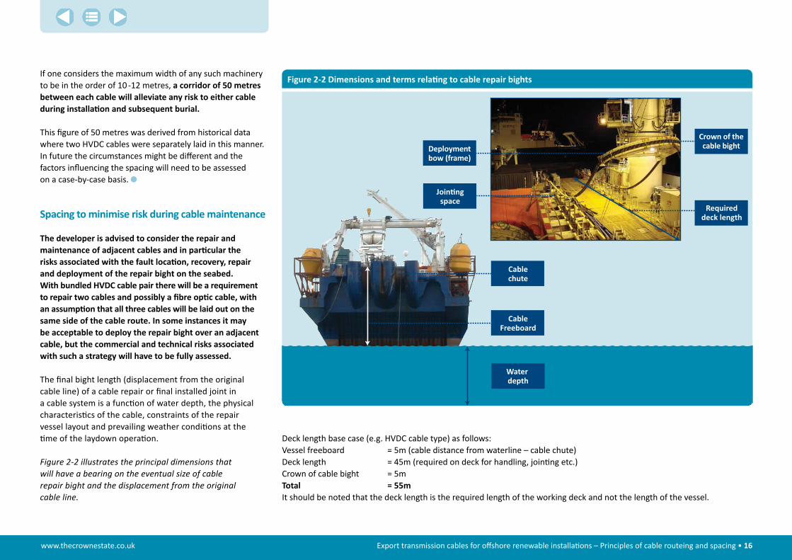
The developer is advised to consider the repair and maintenance of adjacent cables and in particular the risks associated with the fault location, recovery, repair and deployment of the repair bight on the seabed. With bundled HVDC cable pair there will be a requirement to repair two cables and possibly a fibre optic cable, with an assumption that all three cables will be laid out on the same side of the cable route. in some instances it may be acceptable to deploy the repair bight over an adjacent cable, but the commercial and technical risks associated with such a strategy will have to be fully assessed.
The final bight length (displacement from the original cable line) of a cable repair or final installed joint in a cable system is a function of water depth, the physical characteristics of the cable, constraints of the repair vessel layout and prevailing weather conditions at the time of the laydown operation.
Figure�2-2�illustrates�the�principal�dimensions�that��will�have�a�bearing�on�the�eventual�size�of�cable��repair�bight�and�the�displacement�from�the�original��cable�line.
Figure 2-2 Dimensions and terms relating to cable repair bights
Water depth
Cablechute
Join ngspace
Requireddeck length
Crown of thecable bightDeployment
bow (frame)
CableFreeboard
Deck length base case (e.g. HVDC cable type) as follows:Vessel freeboard = 5m (cable distance from waterline – cable chute)Deck length = 45m (required on deck for handling, jointing etc.)Crown of cable bight = 5mtotal = 55mIt should be noted that the deck length is the required length of the working deck and not the length of the vessel.

www.thecrownestate.co.uk Export transmission cables for offshore renewable installations – Principles of cable routeing and spacing • 17
Table�2-3�illustrates�a�repair�bight�with�the�displacement�from�the�original�cable�route�(a)�and�the�recommended�corridor�width�for�future�repair�bight�access.
Table�2-3�provides�an�assessment�of�base�case�repair�bight�lengths�for�a�range�of�water�depths�up�to�200�metres.�An�additional�corridor�providing�for�future�cable�repair�access��is�also�included�for�consideration�whilst�acknowledging��that�the�probability�of�carrying�out�a�subsequent�cable��repair�at�the�crown�of�the�repair�bight�is�likely�to�be�very��low.�The�dimensions�in�table�columns�‘a’�and�‘b’�equate��to�the�‘a’�and�‘b’�dimensions�in�Figure�2-3.�
It must be emphasised that this serves as an illustration of minimum distances and does not constitute a definitive case. Extra distance will most likely be required to correctly set the cable catenary in a repair situation but the variable nature of this renders it impractical to include in a table.
The effects of induced eMf on navigation and the ecology
It is common practice to block the direct electric field from HV cables using conductive sheathing. Thus, the EMF from both HVDC and HVAC power cables emitted into the marine environment are the magnetic field and the resultant induced electric field.
Unlike the magnetic field from a HVAC cable, which is reversed in polarity at the same frequency as the alternating current, the magnetic field from a HVDC cable will have a direct influence on the intensity of the local geomagnetic field.
For export cables of greater length than 60 to 80km it is assumed that HVDC cables will be utilised and
Figure 2-3 Final bight access requirements (‘a’ and ‘b’ defined in Table 2-3)
a. Repair bight length
Original cable route
Repair bight
b.
Water depth (metres) cable repair bight displacement (metres)Additional corridor width for future access to repair bight (metres)
‘a’ ‘b’
MinimumWater depth + freeboard + repair bight crown + deck length
50
10 -100Water depth + freeboard + repair bight crown + deck length
100
100 -200Water depth + freeboard + repair bight crown + deck length
200
Table 2-3 Cable repair bights – minimum dimensions
www.thecrownestate.co.uk Export transmission cables for offshore renewable installations – Principles of cable routeing and spacing • 18
a handful of studies have examined the response to induced EMF’s from power cables. Some would suggest a response (e.g. Gill�et�al.�2009), whilst others do not (e.g. Andrulewicz�et�al.�2003).
What is evident is that there are many electro-sensitive fish, which are potentially capable of responding to anthropogenic sources of electrical field. However, it is not clear whether the interaction between the fish and the artificial electrical field will result in a response or have any consequences for the fish³.
© R
edPe
ngui
n
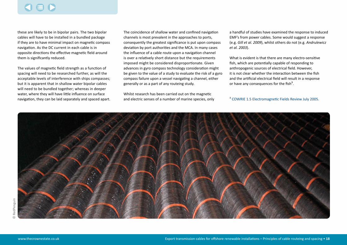
these are likely to be in bipolar pairs. The two bipolar cables will have to be installed in a bundled package if they are to have minimal impact on magnetic compass navigation. As the DC current in each cable is in opposite directions the effective magnetic field around them is significantly reduced.
The values of magnetic field strength as a function of spacing will need to be researched further, as will the acceptable levels of interference with ships compasses; but it is apparent that in shallow water bipolar cables will need to be bundled together; whereas in deeper water, where they will have little influence on surface navigation, they can be laid separately and spaced apart.
The coincidence of shallow water and confined navigation channels is most prevalent in the approaches to ports, consequently the greatest significance is put upon compass deviation by port authorities and the MCA. In many cases the influence of a cable route upon a navigation channel is over a relatively short distance but the requirements imposed might be considered disproportionate. Given advances in gyro compass technology consideration might be given to the value of a study to evaluate the risk of a gyro compass failure upon a vessel navigating a channel, either generally or as a part of any routeing study.
Whilst research has been carried out on the magnetic and electric senses of a number of marine species, only ³ COWRIE 1.5 Electromagnetic Fields Review July 2005.

www.thecrownestate.co.uk Export transmission cables for offshore renewable installations – Principles of cable routeing and spacing • 19
Anticipated EMF’s can be modelled easily as long as specific information on the cable design, extent of burial, cable sheathing, current (amps) and the geomagnetic field strength (DC cable) is available.
There are several engineering solutions that can be considered to reduce EMF emissions. As some of these simultaneously provide protection for the cable, incorporation into the project design can be done without significant additional cost implications. Design considerations include current flow, cable configuration, and sheath/armoring characteristics. Cable design and voltage are the factors that are likely to have the greatest effect on magnetic field generation. Magnetic fields from HVDC cables can be minimised by placing the HVDC cables close together allowing the field vectors from each cable to cancel each other out. Sheathing the cable and increasing the conductivity and permeability of the sheaths also reduce the magnetic field.
Observations and recommendations
stakeholder agreementThe report provides a number of worked examples that are designed to illustrate the conclusions from the study. The figures quoted are not designed to be prescriptive. They are intended to provide only an indicative spacing between cables to give developers an appreciation of various scenarios and it is proposed that a risk based approach will form the foundation of any cable spacing advocated in the route development.
It is important that all stakeholders reach agreement on mutually acceptable spacing without restraining the investment and expansion of offshore renewable energy or compromising the development of other commercial enterprises. ©
Dee
poce
an

www.thecrownestate.co.uk Export transmission cables for offshore renewable installations – Principles of cable routeing and spacing • 20
The spacing between cables should be considered as part of the overall cable protection strategy on a case-by-case basis in conjunction with a site specific risk assessment. When advocating a specific spacing between adjacent cables, the developer will need to assess the operational and technical risks against his own commercial interests and those of the investors and other financial stakeholders.
the use of ais data in reducing risks to aceptable levelsIn order to establish the “safe spacing” so as to reduce the risk to acceptable levels, analysis of AIS data and the filtering of ship movement tracks to identify anchoring activity is recommended. The Desk Top Study should make use of site specific AIS data to obtain a clear indication of all shipping movements in a specific area. The Marine Route Survey should specifically obtain preliminary information on the nature of the seabed in areas where the hazards from shipping activity are at the highest level.
The advantage of using AIS data at the desk top study stage is that it provides an immediate indication of the areas of elevated risk. It is also possible to translate the data into cable fault probabilities using mathematical modelling.
4 Taken from “The Threat of Damage to Submarine Cables by the Anchors of Ships Underway” – Mick Green and Keith Brooks.
Further investigations into the effects of induced eMfThe values of magnetic field strength as a function of spacing will need to be researched further, as will the acceptable levels of interference with ships compasses.
Given advances in gyro compass technology consideration might be given to the value of a study into the risk and incidence of gyro compass failure of a vessel navigating a channel, either generally or as a part of any routeing study.
Further research is also recommended to reach a better understanding of the effects and consequences of induced magnetic and electric fields on various marine species.
incidence of anchor damageThe International Cable Protection Committee (ICPC) has been proactive in highlighting the increasing trend of vessels inadvertently dropping their anchors whilst underway and has lobbied Protection and Indemnity Clubs to communicate with shipping companies in the hope that they will pay attention to their insurers.
Further action is required at a higher level and it is recommended that the representatives of RenewableUK
and Subsea Cables UK lobby the International Maritime Organisation (IMO) and invite them to consider4:• Whether the securing of anchors prior to passage
should be minimum standard methodology and a mandatory requirement
• The introduction of interlocks on anchors when secured for sea passage with an alarm on the bridge
• Securing of the anchor for sea with the interlock in place or a reason why the interlock is not used entered in the logbook and subject to inspection
• Greater promulgation of problems through Marine Guidance Notices
• Wider port inspections by State authorities following any cable failures due to anchors.
The IMO should also consider the affects of reduced manning, fatigue, frequent port calls and the standards of competency, which might which might detrimentally influence quality of performance and what may be expected of the ordinary practice of seamen.
© RedPenguin

www.thecrownestate.co.uk Export transmission cables for offshore renewable installations – Principles of cable routeing and spacing • 21
Appendix 1 – Summary of key technical issues
Overall strategy for conducting the studyThis Appendix provides detailed assessments and supplementary background information to the key factors affecting cable spacing as discussed in section 2 and is provided to give detail to the findings and to support all stakeholders in the development and planning of an offshore transmission network.
It should be recognised that cable spacing forms part of the broader cable protection strategy. Where cable burial is not possible or insufficient to guarantee cable security for instance, cable spacing becomes more important.
summary of key issuesThe cable spacing study identified a number of Issues and these are summarised below:• Cable route planning and early development• Technical and operational factors• Vessel types and position management systems• Subsea equipment• Cable installation and maintenance• Effects of induced emf on the environment
and ecology• Commercial impact of having multiple transmission
cables unavailable at the same time• The interactions between transmission assets
avoiding or minimising the need for proximity and/or crossing agreements
• The potential impact on interruption insurance or the level or availability of investment from as yet unidentified investment groups
• The potential inter-activity between transmission routes leading to a different burial protection index and/or cost
• The considerations of SQSS limits.
Early planning and developmentIn the development of any offshore wind farm it is important that all stakeholders should be engaged as soon as practicable. This is particularly important in the planning and development of the offshore transmission cable network, as this arguably has the greatest impact on other seabed users and other marine activities.
The design route for a submarine cable is generally established in two distinct stages. The first stage is to undertake a Desk Top Study (also called a Cable Route Study) and the second stage is to undertake the Marine Route Survey.
The Desk Top Study will identify the restricted areas and exclusion zones that have to be avoided, but in all likelihood the proposed route will continue to interact with other parties and they should be consulted throughout the planning and development stage.
A successful and well-received offshore wind development requires extensive research and careful planning. To enable the efficient progression of a wind farm project the developer should conduct a thorough assessment of the likely environmental and economic constraints.
The initial desk top assessment of the proposed development will provide a ready opportunity for identifying potential
conflicts. Using data from a number of disparate sources the developer will draw up a constraint map to document the environmental concerns and restrictions that might conflict with the potential wind farm site and to plan further investigation with the aim of quantifying any potential impacts or interactions.
With an offshore development constraints will typically range from public opposition at a local level through to limitations imposed by other users such as fishing, shipping, military, offshore exploration, ecology and tourism.
It is accepted that the proposed cable routeing might change during the course of the planning, particularly after the Marine Route Survey. Whilst a developer might not be able to provide all details of the proposed cable routeing it might be favourable to enter into a high level Memorandum of Understanding with other involved parties, before the developer submits the formal consent application. This would hopefully avoid any objection to the application at a later date. Both parties to the MOU would agree to make technical studies and impact assessments and determine the level of risk involved and if necessary discuss potential mitigating actions.
It may be worth noting that this would be a voluntary exercise, as in many cases sufficient agreement with stakeholders can be achieved through timely and early consultation. The requirement to enter into a formal MOU could easily introduce an added complication to the process.
The developer will present the proposed routeing and justify their particular case using cable spacing principles suggested
www.thecrownestate.co.uk Export transmission cables for offshore renewable installations – Principles of cable routeing and spacing • 22
in the Report. The cable corridor will be assessed and agreed by The Crown Estate before the developer seeks final consent from the planning authority. Whilst not wanting to fetter the development, The Crown Estate in particular will need assurance that any proposed spacing will not unnecessarily exclude the seabed for other commercial interests.
Cable route developmentWithin UK EEZ waters the initial course of any transmission network is largely determined by the location of, and distance to, the optimum connection point(s) onshore.
Assessing the capacity of the onshore network to take up the generated offshore power further influences the choice of landing and connection point and it is important that the design process is interactive from the offset. Ultimately the final choice of connection point is determined by finding an economic balance between the offshore and onshore assets required.
As noted above the first stage in any route development is the Desk Top Study.
The minimum technical requirements for a Desk Top Study are the subject of an ICPC Recommendation and this is attached as Appendix 3. The Study will aim to identify many factors that might affect the long term security of the cable. These will include:• Natural hazards• Man-made hazards• Seabed characteristics• Conflicts with other offshore activity• Environmental impacts.
As part of a Desk Top Study the direct end-to-end route between the offshore generation site and the landing point is amended to avoid any exclusion and restricted areas
determined by a suitable GIS based routeing system and to take into account any risk management strategy including providing security of supply through diversity of route(s) where multiple export transmission cables may be required.
Once the Desk Top Study has identified a suitable route it will be necessary to conduct a Marine Route Survey. This will be divided into two parts. The first, a geophysical survey, will include, bathymetry, contouring, seabed surface and subsurface profiling, core sampling and the use of magnetometer readings to confirm the location of buried cables or pipelines.
The second phase, a geotechnical survey will make an assessment of the soil conditions to determine the cable protection measures that might be required. Of these cable burial is the most effective, but other methods may be more appropriate at cable crossing points for instance or where the cable crosses areas of exposed rock or particularly hard seabed where minimal or no burial is possible.
The target burial depth can be varied along the length of the cable route depending on the perceived hazards and the nature of the seabed.
A Burial Assessment will indicate the likely success and extent of any burial. The evaluation will be made by direct sampling using such techniques as cone penetrometer tests (CPT) to indicate the optimum burial depth or perhaps by deploying towed burial assessment tools.
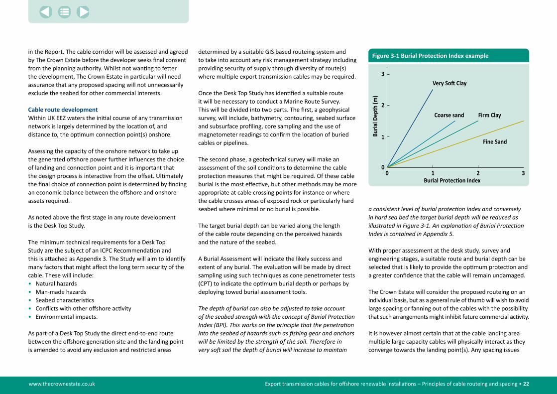
The�depth�of�burial�can�also�be�adjusted�to�take�account��of�the�seabed�strength�with�the�concept�of�Burial�Protection�Index�(BPI).�This�works�on�the�principle�that�the�penetration�into�the�seabed�of�hazards�such�as�fishing�gear�and�anchors�will�be�limited�by�the�strength�of�the�soil.�Therefore�in��very�soft�soil�the�depth�of�burial�will�increase�to�maintain��
a�consistent�level�of�burial�protection�index�and�conversely��in�hard�sea�bed�the�target�burial�depth�will�be�reduced�as�illustrated�in�Figure�3-1.�An�explanation�of�Burial�Protection�Index�is�contained�in�Appendix�5.�
With proper assessment at the desk study, survey and engineering stages, a suitable route and burial depth can be selected that is likely to provide the optimum protection and a greater confidence that the cable will remain undamaged.
The Crown Estate will consider the proposed routeing on an individual basis, but as a general rule of thumb will wish to avoid large spacing or fanning out of the cables with the possibility that such arrangements might inhibit future commercial activity.
It is however almost certain that at the cable landing area multiple large capacity cables will physically interact as they converge towards the landing point(s). Any spacing issues
Figure 3-1 Burial Protection Index example
1
2
3
0 20
1 3Burial Protec�on Index
Very So� Clay
Coarse sand Firm Clay
Fine Sand
www.thecrownestate.co.uk Export transmission cables for offshore renewable installations – Principles of cable routeing and spacing • 23
will therefore probably give way to other security measures including increased protection of the cables.
cable routeing and anchor studyFaults to submarine telecommunications cables have been monitored by the International Cable Protection Committee (ICPC) since its formation in 1958. It has been universally believed that the main cause of cable damage was through fishing. The increased use of AIS to identify vessels shows that cable faults caused by the dragging of anchors whilst the ship is underway is more common than previously believed.
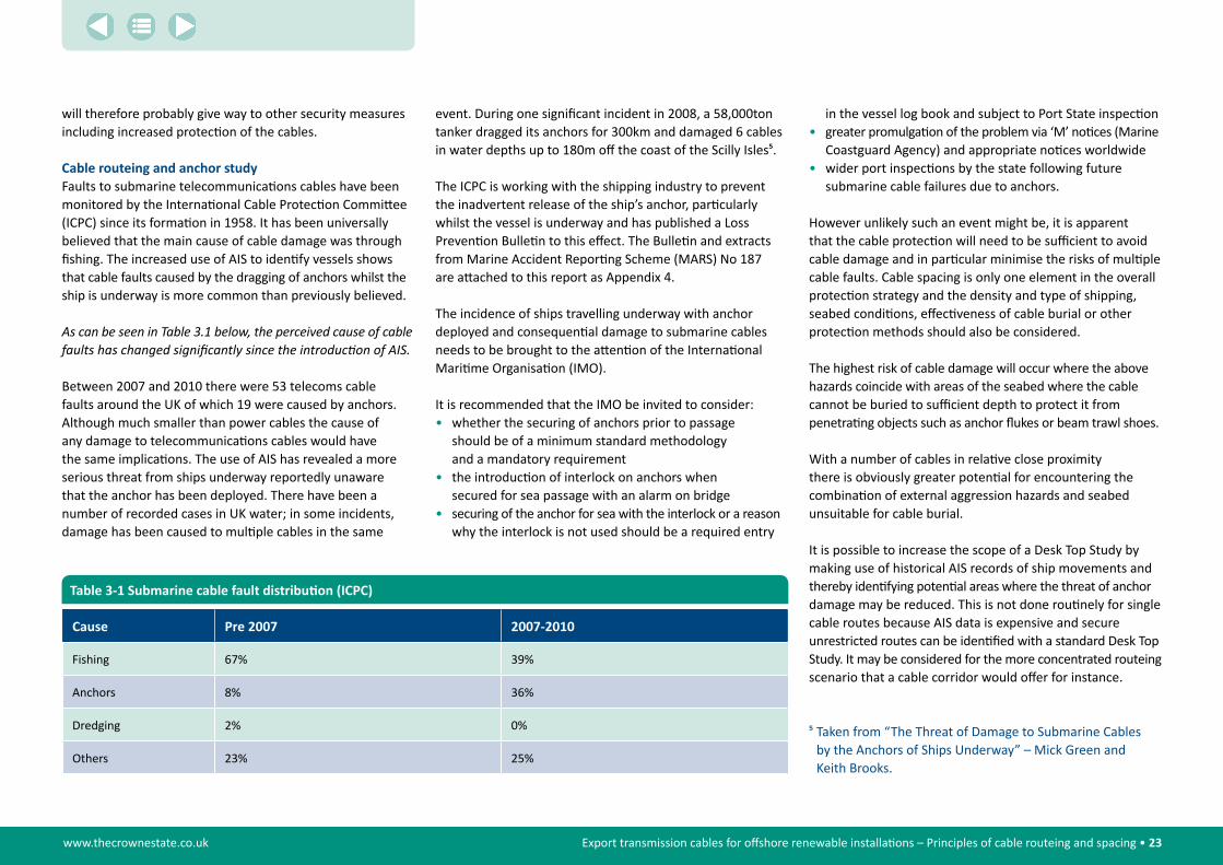
As�can�be�seen�in�Table�3.1�below,�the�perceived�cause�of�cable�faults�has�changed�significantly�since�the�introduction�of�AIS.
Between 2007 and 2010 there were 53 telecoms cable faults around the UK of which 19 were caused by anchors. Although much smaller than power cables the cause of any damage to telecommunications cables would have the same implications. The use of AIS has revealed a more serious threat from ships underway reportedly unaware that the anchor has been deployed. There have been a number of recorded cases in UK water; in some incidents, damage has been caused to multiple cables in the same
event. During one significant incident in 2008, a 58,000ton tanker dragged its anchors for 300km and damaged 6 cables in water depths up to 180m off the coast of the Scilly Isles5.
The ICPC is working with the shipping industry to prevent the inadvertent release of the ship’s anchor, particularly whilst the vessel is underway and has published a Loss Prevention Bulletin to this effect. The Bulletin and extracts from Marine Accident Reporting Scheme (MARS) No 187 are attached to this report as Appendix 4.
The incidence of ships travelling underway with anchor deployed and consequential damage to submarine cables needs to be brought to the attention of the International Maritime Organisation (IMO).
It is recommended that the IMO be invited to consider: • whether the securing of anchors prior to passage
should be of a minimum standard methodology and a mandatory requirement
• the introduction of interlock on anchors when secured for sea passage with an alarm on bridge
• securing of the anchor for sea with the interlock or a reason why the interlock is not used should be a required entry
in the vessel log book and subject to Port State inspection • greater promulgation of the problem via ‘M’ notices (Marine
Coastguard Agency) and appropriate notices worldwide • wider port inspections by the state following future
submarine cable failures due to anchors.
However unlikely such an event might be, it is apparent that the cable protection will need to be sufficient to avoid cable damage and in particular minimise the risks of multiple cable faults. Cable spacing is only one element in the overall protection strategy and the density and type of shipping, seabed conditions, effectiveness of cable burial or other protection methods should also be considered.
The highest risk of cable damage will occur where the above hazards coincide with areas of the seabed where the cable cannot be buried to sufficient depth to protect it from penetrating objects such as anchor flukes or beam trawl shoes.
With a number of cables in relative close proximity there is obviously greater potential for encountering the combination of external aggression hazards and seabed unsuitable for cable burial.
It is possible to increase the scope of a Desk Top Study by making use of historical AIS records of ship movements and thereby identifying potential areas where the threat of anchor damage may be reduced. This is not done routinely for single cable routes because AIS data is expensive and secure unrestricted routes can be identified with a standard Desk Top Study. It may be considered for the more concentrated routeing scenario that a cable corridor would offer for instance.
cause Pre 2007 2007-2010
Fishing 67% 39%
Anchors 8% 36%
Dredging 2% 0%
Others 23% 25%
Table 3-1 Submarine cable fault distribution (ICPC)
5 Taken from “The Threat of Damage to Submarine Cables by the Anchors of Ships Underway” – Mick Green and Keith Brooks.
www.thecrownestate.co.uk Export transmission cables for offshore renewable installations – Principles of cable routeing and spacing • 24
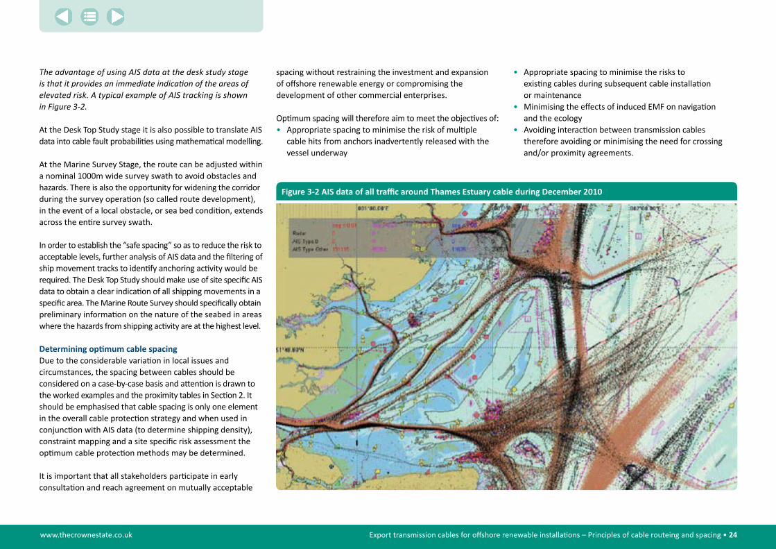
The�advantage�of�using�AIS�data�at�the�desk�study�stage��is�that�it�provides�an�immediate�indication�of�the�areas�of�elevated�risk.�A�typical�example�of�AIS�tracking�is�shown��in�Figure�3-2.
At the Desk Top Study stage it is also possible to translate AIS data into cable fault probabilities using mathematical modelling.
At the Marine Survey Stage, the route can be adjusted within a nominal 1000m wide survey swath to avoid obstacles and hazards. There is also the opportunity for widening the corridor during the survey operation (so called route development), in the event of a local obstacle, or sea bed condition, extends across the entire survey swath.
In order to establish the “safe spacing” so as to reduce the risk to acceptable levels, further analysis of AIS data and the filtering of ship movement tracks to identify anchoring activity would be required. The Desk Top Study should make use of site specific AIS data to obtain a clear indication of all shipping movements in a specific area. The Marine Route Survey should specifically obtain preliminary information on the nature of the seabed in areas where the hazards from shipping activity are at the highest level.
Determining optimum cable spacingDue to the considerable variation in local issues and circumstances, the spacing between cables should be considered on a case-by-case basis and attention is drawn to the worked examples and the proximity tables in Section 2. It should be emphasised that cable spacing is only one element in the overall cable protection strategy and when used in conjunction with AIS data (to determine shipping density), constraint mapping and a site specific risk assessment the optimum cable protection methods may be determined.
It is important that all stakeholders participate in early consultation and reach agreement on mutually acceptable
spacing without restraining the investment and expansion of offshore renewable energy or compromising the development of other commercial enterprises.
Optimum spacing will therefore aim to meet the objectives of:• Appropriate spacing to minimise the risk of multiple
cable hits from anchors inadvertently released with the vessel underway
• Appropriate spacing to minimise the risks to existing cables during subsequent cable installation or maintenance
• Minimising the effects of induced EMF on navigation and the ecology
• Avoiding interaction between transmission cables therefore avoiding or minimising the need for crossing and/or proximity agreements.
Figure 3-2 AIS data of all traffic around Thames Estuary cable during December 2010
www.thecrownestate.co.uk Export transmission cables for offshore renewable installations – Principles of cable routeing and spacing • 25
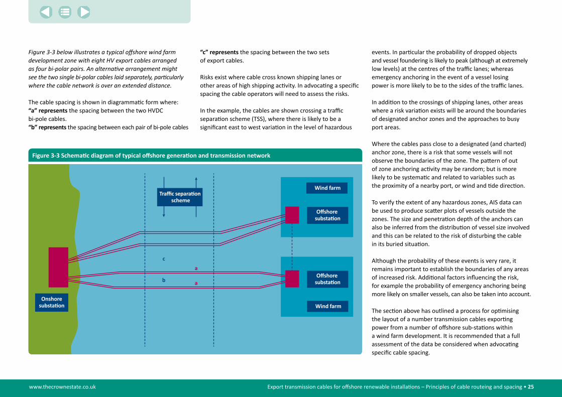
Figure�3-3�below�illustrates�a�typical�offshore�wind�farm�development�zone�with�eight�HV�export�cables�arranged��as�four�bi-polar�pairs.�An�alternative�arrangement�might��see�the�two�single�bi-polar�cables�laid�separately,�particularly�where�the�cable�network�is�over�an�extended�distance.
The cable spacing is shown in diagrammatic form where:“a” represents the spacing between the two HVDC bi-pole cables.“b” represents the spacing between each pair of bi-pole cables
Wind farm
Onshoresubsta�on
c
b
a
Traffic separa�on scheme
Wind farm
a
Offshore substa�on
Offshore substa�on
Figure 3-3 Schematic diagram of typical offshore generation and transmission network
“c” represents the spacing between the two sets of export cables.
Risks exist where cable cross known shipping lanes or other areas of high shipping activity. In advocating a specific spacing the cable operators will need to assess the risks.
In the example, the cables are shown crossing a traffic separation scheme (TSS), where there is likely to be a significant east to west variation in the level of hazardous
events. In particular the probability of dropped objects and vessel foundering is likely to peak (although at extremely low levels) at the centres of the traffic lanes; whereas emergency anchoring in the event of a vessel losing power is more likely to be to the sides of the traffic lanes.
In addition to the crossings of shipping lanes, other areas where a risk variation exists will be around the boundaries of designated anchor zones and the approaches to busy port areas.
Where the cables pass close to a designated (and charted) anchor zone, there is a risk that some vessels will not observe the boundaries of the zone. The pattern of out of zone anchoring activity may be random; but is more likely to be systematic and related to variables such as the proximity of a nearby port, or wind and tide direction.
To verify the extent of any hazardous zones, AIS data can be used to produce scatter plots of vessels outside the zones. The size and penetration depth of the anchors can also be inferred from the distribution of vessel size involved and this can be related to the risk of disturbing the cable in its buried situation.
Although the probability of these events is very rare, it remains important to establish the boundaries of any areas of increased risk. Additional factors influencing the risk, for example the probability of emergency anchoring being more likely on smaller vessels, can also be taken into account.
The section above has outlined a process for optimising the layout of a number transmission cables exporting power from a number of offshore sub-stations within a wind farm development. It is recommended that a full assessment of the data be considered when advocating specific cable spacing.

www.thecrownestate.co.uk Export transmission cables for offshore renewable installations – Principles of cable routeing and spacing • 26
It is also possible to conduct mathematical modelling to translate specific AIS data into cable fault probabilities.
It is not known if this type of modelling can be used to identify an optimum spacing of cables in relative close proximity. In order to answer this question it is recommended that some risk modelling work be carried out over a small section of the proposed cable route, for example where the cables intersect busy shipping lanes.
The cable operator will also need to consider the effects of induced EMF in determining the optimum spacing between bi-pole cables (“a” in Figure 3-3). This is discussed further on page 27-28.
Technical and operational nets security and Quality of supply standardThe Security and Quality of Supply Standard (SQSS) sets out the minimum criteria that transmission licensees must comply with and requires that consideration should be given to the operation and maintenance of the National Electricity Transmission System (NETS). In this context the NETS consists of both the Onshore Transmission System and the Offshore Transmission System.
Any prospective transmission owner (OFTO) would more than likely come in after the offshore transmission infrastructure has been connected to the grid and developers would need to show prospective owners that the cable route was properly planned and engineered to meet the required quality and security of supply criteria. In particular the issue of security of supply for the overall system will be under consideration and thus security and diversity of the transmission routes scrutinised. This is particularly relevant in regard to multiple cable hits where a sequence of supply failures could have a serious consequential loss to the whole UK network.
The loss of a high capacity transmission cable could have a serious consequence on the sustainability of the UK transmission network and the risk of such an occurrence could be against the principles of the SQSS.
cable technologiesThe large generating capacities of Round 3 wind farms and their distances from potential connection points, along with the increasing complexity of the overall system, highlights the critical importance of offshore transmission both as a significant capital cost and as a sustained revenue source.
When planning and designing a transmission system the developer must consider the overall system including cable, transformers and converters. Generally where HVAC systems
are technically possible, they are usually more economically viable. The cost of HVDC cable is usually cheaper and has limited power losses, but the costs and losses of DC converters are significantly higher than that of AC transformers.
Any decision on the appropriate offshore transmission technology will depend on a number of factors, but ultimately the distance of the offshore generation to the onshore AC network will be the deciding factor. Depending on voltage level, HVAC can be considered technically viable up to 100km.
Consequently HVDC transmission is more appropriate over longer distances, particularly in some of the more remote offshore wind installations proposed in Round 3 and in general the HVDC solution becomes more economically viable when the transmission distance is between 60km and 80km. It should be noted that HVAC technology will generally be used in Round 3 developments that lie within this distance6.
Mass Impregnated cables have been the traditional medium for transmission in DC systems until more recently. As the name suggests the conductors are insulated with special paper impregnated with a high viscosity compound. They can be used for voltages up to 600kV.
More recently, as the interest in Voltage Source Converter technology has grown, XLPE cables have also been developed that rely on extruded polyethylene as the insulation medium for the conductors. These cables are easier to manufacture and correspondingly cheaper than a mass Impregnated equivalent and also offer a lighter weight, however currently they can only operate at voltages up to 300kV, which limits possible power flow.
6 The National Grid Round 3 Offshore Wind Farm Connection Study on behalf of The Crown Estate.©
Dee
poce
an
www.thecrownestate.co.uk Export transmission cables for offshore renewable installations – Principles of cable routeing and spacing • 27
Current HVDC technology uses 320kV XLPE cables capable of transmitting 1200 MW, with 500kV cables being developed. XLPE insulated cables are also available for HVAC 3 phase systems up to 420kV transmitted down each of three conductors.
Offshore connection, transmission and redundancyTo date the offshore transmission infrastructure has been delivered on a radial (point to point) basis, which reflected the characteristics of the offshore developments and the constraints and technologies available at the time. However, there are questions as to whether this approach will be suitable in the future, (limited resources, cable supply, platforms, planning and consenting constraints inshore) and the need to consider a more coordinated transmission infrastructure is now more pressing than ever.
Several studies have shown that a coordinated HVDC voltage-source converters transmission strategy could interconnect a number of large offshore wind farms, and eventually, connect them to other European onshore networks, delivering significant economic and environmental benefits.
The Offshore Electricity Grid Infrastructure in Europe Report7 published in October, recommends the connection of wind farm clusters to offshore hubs rather than the
current practice of point-to-point cables to shore, but recognises that there are significant political, commercial and technical hurdles to overcome.
The significant growth in intermittent generation, such as offshore wind, has raised concerns regarding the transmission network in relation to the Main Interconnected Transmission System (MITS) and in particular to a possible reduction in power output during peak demand periods.
Offshore wind generation in England and Wales, together with the potential connection of new nuclear power stations, raises a number of regional connection issues, particularly in Wales (North & Central), the South West and along the English East Coast between the Humber and East Anglia.
It is apparent that a more coordinated transmission system commensurate with the scale of offshore (and other) renewable energy supplies has to be considered and it makes sense to evolve the transmission network before the increased volumes of wind-generated power have been developed.
Within the normal generation regime additional generating plant is held in reserve to cover possible faults across the network.
A single point-to-point (radial) offshore transmission network offers no alternative route to the shore in the event of a failure. In this instance the onshore generation plant held in reserve will be activated to cover the loss in electrical output.
A coordinated transmission network on the other hand has the potential to reduce the risk by offering alternative transmission routes due to the wider network connections and as a consequence significantly reduce the system operating costs.
Effects of induced eMf on the environment and ecologyWithin the marine environment the Earth’s geomagnetic field is the predominant electromagnetic field. Anthropogenic (man made) electromagnetic fields from subsea power cables have been introduced into the marine environment for over a century. It is common practice to block the direct electric field from HV cables using conductive sheathing. Thus, the EMF from both HVDC and HVAC power cables emitted into the marine environment are the magnetic field and the resultant induced electric field.
7 The Offshore Connection Grid Infrastructure in Europe Report on behalf of EWEA and others October 2011.
© The Crown Estate, RedPenguin, Deepocean
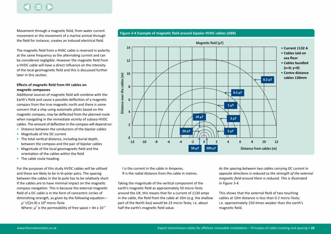
www.thecrownestate.co.uk Export transmission cables for offshore renewable installations – Principles of cable routeing and spacing • 28
Movement through a magnetic field, from water current movement or the movement of a marine animal through the field for instance, creates an induced electrical field.
The magnetic field from a HVAC cable is reversed in polarity at the same frequency as the alternating current and can be considered negligible. However the magnetic field from a HVDC cable will have a direct influence on the intensity of the local geomagnetic field and this is discussed further later in this section.
Effects of magnetic field from HV cables on magnetic compasses Additional sources of magnetic field will combine with the Earth's field and cause a possible deflection of a magnetic compass from the true magnetic north and there is some concern that a ship using automatic pilots based on the magnetic compass, may be deflected from the planned route when navigating in the immediate vicinity of subsea HVDC cables. The amount of deflection in the compass will depend on:• Distance between the conductors of the bipolar cables• Magnitude of the DC current• The total vertical distance, including burial depth,
between the compass and the pair of bipolar cables• Magnitude of the local geomagnetic field and the
orientation of the cables within the field• The cable route heading.
For the purposes of this study HVDC cables will be utilised and these are likely to be in bi-polar pairs. The spacing between the cables in the bi-pole has to be relatively short if the cables are to have minimal impact on the magnetic compass navigation. This is because the external magnetic field of a DC cable is in the form of concentric circles of diminishing strength, as given by the following equation:–
μ° I/(2π.R) x 106 micro-TeslaWhere: μ° is the permeability of free space = 4π x 10-7
I is the current in the cable in Amperes.R is the radial distance from the cable in metres.
Taking the magnitude of the vertical component of the earth’s magnetic field as approximately 50 micro-Tesla around the UK; this means that for a current of 1130 amps in the cable, the field from the cable at 10m (e.g. the shallow part of the North Sea) would be 23 micro-Tesla; i.e. about half the earth’s magnetic field value.
0.2 μT
0.5 μT
1 μT
2 μT
5 μT
10 μT
50 μT 200 μT
20 μT
14
12
10
8
6
4
2
0-12 -10 -8 -6 -4 -2 0 12108642
Distance from cables (m)
Magne�c field (μT)
Figure 3-4 Example of magnetic field around bipolar HVDC cables (ABB)
As�the�spacing�between�two�cables�carrying�DC�current�in�opposite�directions�is�reduced�so�the�strength�of�the�external�magnetic�field�around�them�is�reduced.�This�is�illustrated��in�Figure�3-4.
This shows that the external field of two touching cables at 10m distance is less than 0.2 micro-Tesla; i.e. approximately 250 times weaker than the earth’s magnetic field.
• Current 1132 A• cables laid on
sea floor• cables bundled
(x=0; y=0)• centre distance
cables 130mm

www.thecrownestate.co.uk Export transmission cables for offshore renewable installations – Principles of cable routeing and spacing • 29
Only magnetic compasses and magnetically driven autopilots can be effected by the magnetic fields produced by HVDC cables and as most vessels are fitted with gyro compasses and GPS based navigational systems,the inherent risks due to a EMF induced compass deviation seem quite small compared to the risks of bad seamanship or professional error, recognising however that the magnetic compass may be the only back-up compass on many vessels.
Effects of induced EMF on local ecologyElectromagnetic fields (EMF) from power cables have been introduced into the marine environment from a variety of sources for many years. Despite this little is known about the ecological impact and it is only more recently, with the development of offshore renewable energy and a greater environmental awareness, that concerns have been raised about the possible effects of multiple subsea power cables on numerous marine species.
Whilst research has been carried out on the magnetic and electric senses of a number of marine species, only a handful of studies have examined the response to induced EMF’s from power cables. Some would suggest a response (e.g. Gill�et�al.�2009), whilst others do not (e.g. Andrulewicz��et�al.�2003). Consequently with wide ranging views and gaps in the fundamental data, conclusions regarding any response to electromagnetic fields are potentially highly speculative. However it is likely that some species, such as rays and sharks will have a high sensitivity to the induced electric component, whilst marine mammals and sea turtles will have a high sensitivity to the magnetic component.
In carrying out research the anticipated EMF can be modelled easily as long as specific information on the cable design, extent of burial, cable sheathing, current (amps) and the geomagnetic field strength (for DC cable) is available.
It is clear that more work is needed to understand the nature and magnitude of any potential impacts to marine species from undersea power cable electromagnetic fields.
There are several engineering solutions that can be considered to reduce EMF emissions. As some of these simultaneously provide protection for the cable, incorporation into the manufacturing process can be done without significant additional cost implications. Design considerations include current flow, cable configuration, and sheath/armoring characteristics.
Cable design and voltage are the factors that are likely to have the greatest effect on magnetic field generation.
Magnetic fields from opposing bipolar DC cables can be minimised by placing the cables close together allowing the field vectors from each cable to cancel each other out. Sheathing the cable and increasing the conductivity and permeability of the sheaths also reduce the magnetic field.
In practice the effects of induced EMF on specific cable systems should be assessed on a case by case basis due to the number of environmental and ecological variables.
Vessel types and position management systemsOffshore renewable energy cable operations have to date been completed using multi-point anchored barges, dedicated cable vessels from the cable sector or multi-purpose support vessels from the oil and gas sector.
Traditionally cable installation and repair vessels have either been multi-point anchored barges with or without self-propulsion suitable for relatively shallow water operations and self-propelled ‘manual control’ cable vessels for operations in deeper waters. The advent
© R
edPe
ngui
n
The values of magnetic field strength as a function of spacing will need to be researched further, as will the acceptable levels of interference with ships compasses; but it is apparent that in shallow water bipolar cables will need to be close together; whereas in deeper water the cables can be spaced further apart.

www.thecrownestate.co.uk Export transmission cables for offshore renewable installations – Principles of cable routeing and spacing • 30
of dynamic positioning in the 1980s has since been widely adopted as the station keeping mode of choice for cable installation and repair vessels.
Navigational and positioning management systems.The two technologies forming the backbone of today’s offshore industry are the Global Positioning System (GPS) and Dynamic Positioning (DP).
DP can operate independently of GPS, but it is the timely development of both these technologies that has had a significant impact on the full range of specialised marine operations relevant to this study. While other positioning systems provide similar reliability and repeatability, GPS based systems provide the most common basis for position referencing on cable operations and are consequently referred to for the purposes of this Study.
For operations relating to cables and other subsea installations the use of GPS and DP for navigation and positioning significantly enhances accuracy and repeatability in terms of knowing where the cable or asset actually is on the seabed and being able to return there time after time.
The station keeping performance capability of any vessel is a combination of design, maintenance standards and operational competence in the face of environmental and site specific conditions. Close attention to safe operating practices, competency assurance and behavioural based safety should be equally important as the technical reliability and performance of vessels and equipment when considering cable spacing issues.
Multi-point anchored bargesMulti-point anchored barges engaged in both wind farm operations and cable work normally deploy a 4, 6 or 8 point mooring system with the scope of wire depending on the
water depth and prevailing conditions but generally in the order of 500-900 metres. Barges engaged in cable burial operations using a towed plough will also deploy a single pulling anchor in the direction of travel. Such a pulling anchor is often deployed on a longer scope of 800-1200 metres. This type of barge will use high holding power anchors capable of deep seabed penetration. Anchors are deployed and recovered by one or more anchor handling tugs and a dedicated tow tug is normally also utilised. The tugs will be integrated into the lay barge navigational system using a Wi-Fi or laser referencing system. These barges may also be fitted with one or more spud legs and/or manoeuvring thrusters to assist positioning.
Self-propelled vessels with manual controlSelf-propelled vessels with only manual positioning control include a wide variety of vessel types engaged in wind farm operations and to a lesser extent cable operations. The level of redundancy in the propulsion and control systems vary considerably but in general vessels operating in close proximity to surface and subsea obstructions, or carrying out position critical operations, are equipped with redundancy in both propulsion and propulsion control. By definition, manual control relies heavily on the competency of the operator, which includes ship handling skills, familiarisation with a particular vessel’s characteristics and knowledge of emergency response actions.
Dynamically positioned vesselsThe classes of dynamically positioned vessels are well known and in brief are as follows:• DP Class 1 – Loss of position may occur in the event
of a single fault.• DP class 2 – Loss of position should not occur from
a single fault of an active component or system such as generators, thruster, switchboards remote controlled valves etc. But may occur after failure
of a static component such as cables, pipes, manual valves etc.
• DP class 3 – Loss of position should not occur from any single failure including a completely burnt fire sub division or flooded watertight compartment.
DP vessels engaged in wind farm operations are generally Class 2 vessels due to the need for reliable station keeping in close proximity to fixed structures and other vessels. Cable vessels engaged in wind farm work are also generally DP Class 2 for the same reason – operations in proximity to fixed structures and other site obstructions.
As the essence of DP notation and the class awarded is a function of the redundancy afforded by the systems and design of the vessel, degradation of these systems may be entirely acceptable in an operational situation if this does not impact on its ability to carry out a specific operation, although it would preclude it from work which specifically required the standard required by the class notation.
In general cable maintenance vessels retained for cable repairs under long term maintenance agreements are generally DP Class 1 vessels or for commercial reasons DP Class 2 vessels operating to Class 1 requirements, however higher specified vessels are often preferred for cable installation work. Working in close proximity to other cables or subsea structures, it would not be unusual for an operator to specify a vessel with DP Class 2 redundancy.
Competence of ship’s Watchkeepers in general is legislated at an international level under the STCW-95 Convention and the specialism of DP operations is now included in the most recent protocol. The Nautical Institute DP training scheme is the industry standard for training and certification of DP operators and maintainers in UK.
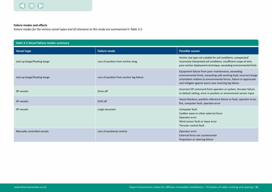
www.thecrownestate.co.uk Export transmission cables for offshore renewable installations – Principles of cable routeing and spacing • 31
Table 3-2 Vessel failure modes summary
Vessel type failure mode Possible causes
Jack-up barge/floating barge Loss of position from anchor dragAnchor size type not suitable for soil conditions, unexpected/incorrectly interpreted soil conditions, insufficient scope of wire, poor anchor deployment technique, exceeding environmental limits
Jack-up barge/floating barge Loss of position from anchor leg failure
Equipment failure from poor maintenance, exceeding environmental limits, exceeding safe working load, incorrect barge orientation relative to environmental forces, failure to appreciate and mitigate against worst case mooring leg failure
DP vessels Drive offIncorrect DP command from operator or system, thruster failure to default setting, error in position or environment sensor input
DP vessels Drift offVessel blackout, position reference failure or fault, operator error, fire, computer fault, operator error
DP vessels Large excursion Computer fault Sudden wave or other external forceOperator errorWind sensor fault or input errorThruster control fault
Manually controlled vessels Loss of positional control Operator errorExternal force not counteractedPropulsion or steering failure
Failure modes and effectsFailure�modes�for�the�various�vessel�types�and�of�relevance�to�this�study�are�summarised�in�Table�3-2.
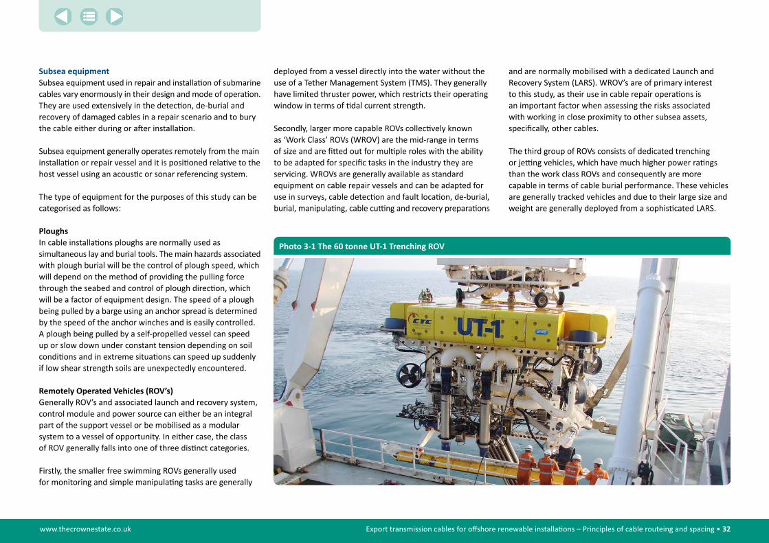
www.thecrownestate.co.uk Export transmission cables for offshore renewable installations – Principles of cable routeing and spacing • 32
subsea equipmentSubsea equipment used in repair and installation of submarine cables vary enormously in their design and mode of operation. They are used extensively in the detection, de-burial and recovery of damaged cables in a repair scenario and to bury the cable either during or after installation.
Subsea equipment generally operates remotely from the main installation or repair vessel and it is positioned relative to the host vessel using an acoustic or sonar referencing system.
The type of equipment for the purposes of this study can be categorised as follows:
PloughsIn cable installations ploughs are normally used as simultaneous lay and burial tools. The main hazards associated with plough burial will be the control of plough speed, which will depend on the method of providing the pulling force through the seabed and control of plough direction, which will be a factor of equipment design. The speed of a plough being pulled by a barge using an anchor spread is determined by the speed of the anchor winches and is easily controlled. A plough being pulled by a self-propelled vessel can speed up or slow down under constant tension depending on soil conditions and in extreme situations can speed up suddenly if low shear strength soils are unexpectedly encountered.
Remotely Operated Vehicles (ROV’s)Generally ROV’s and associated launch and recovery system, control module and power source can either be an integral part of the support vessel or be mobilised as a modular system to a vessel of opportunity. In either case, the class of ROV generally falls into one of three distinct categories.
Firstly, the smaller free swimming ROVs generally used for monitoring and simple manipulating tasks are generally
deployed from a vessel directly into the water without the use of a Tether Management System (TMS). They generally have limited thruster power, which restricts their operating window in terms of tidal current strength.
Secondly, larger more capable ROVs collectively known as ‘Work Class’ ROVs (WROV) are the mid-range in terms of size and are fitted out for multiple roles with the ability to be adapted for specific tasks in the industry they are servicing. WROVs are generally available as standard equipment on cable repair vessels and can be adapted for use in surveys, cable detection and fault location, de-burial, burial, manipulating, cable cutting and recovery preparations
and are normally mobilised with a dedicated Launch and Recovery System (LARS). WROV’s are of primary interest to this study, as their use in cable repair operations is an important factor when assessing the risks associated with working in close proximity to other subsea assets, specifically, other cables.
The third group of ROVs consists of dedicated trenching or jetting vehicles, which have much higher power ratings than the work class ROVs and consequently are more capable in terms of cable burial performance. These vehicles are generally tracked vehicles and due to their large size and weight are generally deployed from a sophisticated LARS.
Photo 3-1 The 60 tonne UT-1 Trenching ROV

www.thecrownestate.co.uk Export transmission cables for offshore renewable installations – Principles of cable routeing and spacing • 33
Jetting legsJetting legs or vertical injectors are rigid legs normally deployed from an anchored barge and used for simultaneous lay and burial of cables into sands or clays capable of being fluidised.
The jetting leg is normally suspended from a barge crane and held back by guide wires as the barge progresses along the lay track. The cable is deployed from a carousel or cable tank through the foot of the leg directly into the soil at the required depth.
Burial depth is controlled by means of raising or lowering the tool. Horizontal positioning is controlled by means of adjusting the barge anchors. Burial depths of 10 metres or more are possible in suitable soil conditions.
The use of jetting legs close to other cables and structures relies on the integrity of the barge anchor spread and competent use of the barge management system to ensure proximity limits are complied with. As the tool is physically connected to the barge, positioning accuracy of the barge is reflected directly as positioning accuracy of the burial tool.
Mass Flow Excavators (MFE)Mass flow excavators could be used for cable de-burial. They operate either as a tracked vehicle or suspended above the work area and use high volume, low pressure pumps to blast non cohesive and weak cohesive soils from the target area. Their use is generally limited to deeper water (>10 metres) due to the minimum water head required for the pumps although smaller capacity MFEs can be operated in shallower depths (>5 metres). The advantage of MFEs lie in their high capacity and the fact that they use pumps to remove soil, thus minimising the possibility of cable damage, although the high turbidity created may give rise to ecological concerns.
Photo 3-2 Deployment of typical HVDC hair pin bight using a deployment bow (frame)
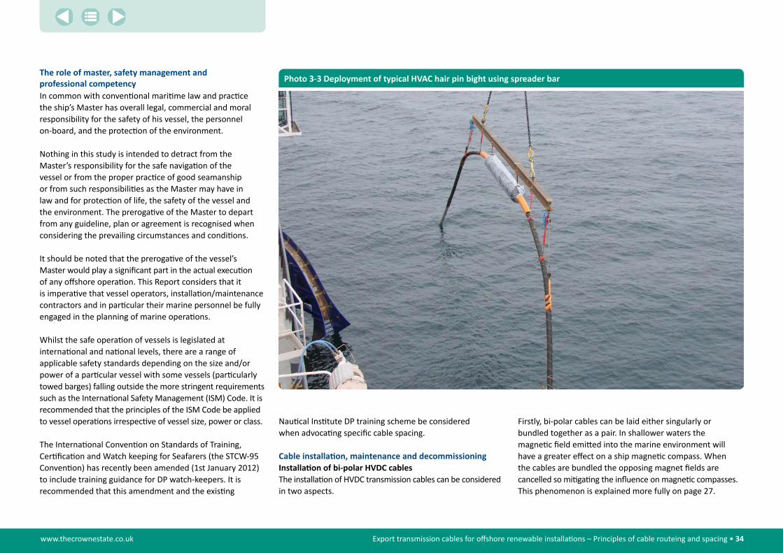
www.thecrownestate.co.uk Export transmission cables for offshore renewable installations – Principles of cable routeing and spacing • 34
the role of master, safety management and professional competencyIn common with conventional maritime law and practice the ship’s Master has overall legal, commercial and moral responsibility for the safety of his vessel, the personnel on-board, and the protection of the environment.
Nothing in this study is intended to detract from the Master’s responsibility for the safe navigation of the vessel or from the proper practice of good seamanship or from such responsibilities as the Master may have in law and for protection of life, the safety of the vessel and the environment. The prerogative of the Master to depart from any guideline, plan or agreement is recognised when considering the prevailing circumstances and conditions.
It should be noted that the prerogative of the vessel’s Master would play a significant part in the actual execution of any offshore operation. This Report considers that it is imperative that vessel operators, installation/maintenance contractors and in particular their marine personnel be fully engaged in the planning of marine operations.
Whilst the safe operation of vessels is legislated at international and national levels, there are a range of applicable safety standards depending on the size and/or power of a particular vessel with some vessels (particularly towed barges) falling outside the more stringent requirements such as the International Safety Management (ISM) Code. It is recommended that the principles of the ISM Code be applied to vessel operations irrespective of vessel size, power or class.
The International Convention on Standards of Training, Certification and Watch keeping for Seafarers (the STCW-95 Convention) has recently been amended (1st January 2012) to include training guidance for DP watch-keepers. It is recommended that this amendment and the existing
Photo 3-3 Deployment of typical HVAC hair pin bight using spreader bar
Nautical Institute DP training scheme be considered when advocating specific cable spacing.
Cable installation, maintenance and decommissioningInstallation of bi-polar HVDC cablesThe installation of HVDC transmission cables can be considered in two aspects.
Firstly, bi-polar cables can be laid either singularly or bundled together as a pair. In shallower waters the magnetic field emitted into the marine environment will have a greater effect on a ship magnetic compass. When the cables are bundled the opposing magnet fields are cancelled so mitigating the influence on magnetic compasses. This phenomenon is explained more fully on page 27.

www.thecrownestate.co.uk Export transmission cables for offshore renewable installations – Principles of cable routeing and spacing • 35
In deeper waters where the two cables will have little influence on magnetic compasses, the two cables can be installed separately. The spacing between the two cables will very much depend on the type of installation vessel and the means by which the two cables are buried. Bundling bi-pole cables may also offer cost savings in vessel time but this should be weighed against the often slower pace of installing bundled cables and the risk that may be imposed by burial equipment to the cables.
Secondly, when installing a cable there is an obvious risk to the cables already in situ. The spacing between the two cables will need to take account of the capability of the installation vessel and the type of subsea burial equipment.
The study has identified three distinct modern installation practices, namely:• system a – Cables are surface laid by a cable
installation vessel, with burial carried out as a separate post-lay operation.
• system b – Cables are laid and buried in a simultaneous operation with burial equipment being towed by the cable laying vessel or barge.
• system c – As for B above, with a separate vessel opening a pre-cut trench. Cable is then positioned into the trench on laying. However, it should be noted that this is not a common method of operation as it requires compliant environmental conditions and can be a very slow operation.
With Round 3 developments and the increase in project size and distance offshore, it is likely that DP cable installation vessels will become the preferred option over conventional anchored lay barges, although landing point and route selection may dictate barge operations in shallow waters. Barge operations further offshore will be limited by safety considerations and generally present a more weather sensitive solution.
cable maintenance requirementsAdvancing technology in cable repair equipment, vessel control and positioning accuracy has made significant contributions to the manner and efficiency of cable repair work. However, this has not removed the need for cables to be brought to the surface to be worked upon.
Fault detection and location on power cables can be difficult and will depend to large degree on the nature of the fault. Fault location may eventually depend on a combination of terminal based equipment and localised sensing in the general area of the fault.
Power cables can present visible signs of fault (such as an HV blow-out) where a search ROV may be able to visually detect signs of the fault or observe effects in the water, but it is common for a combination of pulse reflection techniques, ROV and electrodes to be used. Depending on the nature of the fault it is a process that could take some days to conclude satisfactorily.
The study of AIS data in the general location could be useful, as it will identify any vessel anchoring or moving slowly over the cable at the time of the incident.
In the case of cable repairs the use of ROV’s to de-bury, cut and recover the cable will, in a majority of cases, be the preferred option, but there are many factors that may prevent this or hamper the efficiency of the cable repair such as poor visibility and/or strong tidal currents. The sea state for launch and recovery of the vehicle will also have a bearing on the operation of most ROV’s. In certain circumstances the use of de-trenching grapnels or mass flow excavators may be considered for de-burial operations, including removal of rock berms, and cranes for the removal of any mattress type protection.
Cable jointing normally takes place in specially adapted jointing container(s) on the working deck can have significant influence on the size of the cable bight.
In-line, laid-in or first repair joints may on certain occasions need to be displaced and laid away from the original line of cable, but in general their placement is not relevant to this study.
cable decommissioning requirementsThere are some examples of de-commissioning and recovery of out of service (OOS) telecoms cables where significant lengths of old cable have been removed to accommodate new systems and conform to environmental requirements. This has been restricted mostly to coastal areas, where new cables seek landing sites in an already congested area or where older cables occupy the optimum seabed and are recovered to make way for new systems.
Recovery of old cables at those points where they cross a new cable system (or other seabed asset) is standard industry practice and forms a part of most installation projects.
To date the removal of large sections of heavy power cables for re-cycling purposes has not proved to be commercially sustainable.
New environmental awareness and environmental legislation will have considerable impact on cable decommissioning. The density of cable networks that are being created by the wind-farm industry, with many cables concentrated in areas often close to shore proving a particularly good illustration of the case. The decommissioning strategy for a given cable system will probably be a balance between minimising negative environmental impacts and releasing seabed space for future developments.

www.thecrownestate.co.uk Export transmission cables for offshore renewable installations – Principles of cable routeing and spacing • 36
Marine planningIn its broadest context, the planning and development of any commercial marine activity is defined within the terms of Marine Spatial Planning, a future based process to address commercial and technical conflicts and to safeguard and manage the ecosystems within the marine environment.
The UK Marine and Coastal Access Act 2009 introduced Marine Spatial Planning and defined arrangements for a new system of marine planning and management across the UK.
In England the 2009 Act provides for the creation of the Marine Management Organisation (MMO). Through the establishment of statutory regional Marine Plans the MMO is responsible for marine policy objectives in English waters. The Act also transferred the responsibilities for planning, licensing and enforcement in Welsh, Scottish and Northern Ireland territorial waters to the respective devolved governments.
The cornerstone of the UK marine planning is the Marine Policy Statement (MPS), which facilitates and supports the creation of regional Marine Plans and reflects the principles of sustainable development through independent “sustainability appraisals”.
The Crown Estate considers the MMO responsible for any regulatory changes, including any that might lead to the introduction of defined corridors for future transmission cables. In line with this the MMO is currently considering whether this might be a workable option. Whilst this Study is not part of this consideration, the generic principles of cable spacing will be relevant to adjacent cables in all situations.
the role of the crown estateThe Crown Estate is a corporate body formed by the Crown Estate Act 1961 and charged by Parliament with the responsibility of managing the property interests of the Crown.
The Marine Estate is one of the four constituent estates that make up these property interests and includes virtually the entire seabed out to the 12 nautical mile territorial limit and includes the rights to explore and utilise the natural resources of the UK continental shelf and renewable energy within the UK REZ.
Under The Crown Estate Act 1961, permission in the form of a license is needed for the rights to lay, maintain and operate cables and pipelines on the seabed within the territorial waters of UK.
The Energy Act 2004 vested rights to The Crown Estate enabling them to lease sites for the generation of renewable energy on the continental shelf within the limits of the UK REZ. Under these rights the permission of The Crown Estate is required for the complete length of an export cable, even when extending beyond the limits of the UK territorial waters. These rights are either granted to the wind farm developer or the dedicated Offshore Transmission Asset Owner (OFTO).
With the continued development of offshore renewable energy and the extension of interconnection The Crown Estate expects to see a significant increase in the number of submarine transmission cables within its area of responsibility. The Crown Estate is taking a proactive role in the development of a strategic offshore transmission network and is working in partnership with the National Grid, DECC and OFGEM to enable a timely and effective delivery of the offshore grid.
In the past The Crown Estate involvement in the development of the Round 1 and 2 offshore wind farms has been limited to the administration of site leases in the landowner role, with selection through competitive tender to develop, construct, finance and operate the offshore projects.
In contrast to previous offshore wind leasing rounds, The Crown Estate’s approach to (and role in) the Round 3 initiative is substantially different. This arises from the fact that Round 3 represents a significant increase in scale of offshore wind development in the UK, and requires a more targeted and programme-led approach than has been applied previously. In addition to co-investment by The Crown the key difference lies in the award of zones rather than specific sites for offshore wind development.
Round 3 comprises nine development zones situated around the UK. Each zone has been awarded to a single zone developer (or a single consortium). The majority of zones will contain multiple offshore wind farm projects within the zone boundary.
The Crown Estate ran a competitive tender process to award zones to potential developers, which concluded with the signing of Zone Development Agreements at the end of 2009. The successful developer must apply to The Crown Estate for an Agreement for Lease for each identified project within the zone and following the granting of statutory consents for the project commence site development in earnest; the developer will then enter into a Lease with The Crown Estate and can commence construction of the project.
Appendix 2 – Highlights of key planning and regulatory framework

www.thecrownestate.co.uk Export transmission cables for offshore renewable installations – Principles of cable routeing and spacing • 37
ICPC Recommendation No. 9, Issue: 4 Issue Date: 6 March 2012
ICPC Recommendation Recommendation No. 9 Minimum Technical Requirements for a
Desktop Study (also known as Cable Route Study)
ICPC Recommendation No. 9, Issue: 4 Issue Date: 6 March 2012
Contact for Enquiries and Proposed Changes If you have any questions regarding this document or suggestions for improving it, please contact:
International Cable Protection Committee Ltd PO Box 150 LymingtonSO41 6WA United Kingdom
Secretary:Tel:Fax:E-mail:ICPC Web-site:
Mr. Graham Marle + 44 1590 681 673 +44 870 432 7761 [email protected] www.iscpc.org
DISCLAIMER An International Cable Protection Committee Ltd ("ICPC") Recommendation ("Recommendation") implies a consensus of those substantially concerned with its scope and provisions. A Recommendation is intended as a guide to aid cable owners and other seabed users in promoting the highest goals of reliability and safety in the submarine cable environment.The existence of a Recommendation does not in any respect preclude anyone, whether he has approved the Recommendation or not, from laying or repairing undersea cables or employing procedures to these ends which may be required by the ordinary practice of seamanship or by the special circumstances of each case, but which may not be conforming to the Recommendation.
The ICPC does not develop standards and will in no circumstances give an interpretation of a Recommendation in the name of the ICPC. The ICPC and its members do not accept any liability for any errors in the Recommendation or for any consequences resulting from its use as a planning guide. Nothing in this Recommendation should be viewed as relieving anyone from the rights and obligations of seabed users under international law, including but not limited to the United Nations Convention of the Law of the Sea ("UNCLOS").
NB: ICPC Recommendations are subject to periodic review and users are cautioned to obtain the latest issues. This Recommendation may be revised or withdrawn at any time without further notice to the recipient.
Page 2 of 16
Appendix 3 – ICPC recommendation No 9
Printed with the kind permission of the International Cable Protection Committee.

www.thecrownestate.co.uk Export transmission cables for offshore renewable installations – Principles of cable routeing and spacing • 38
ICPC Recommendation No. 9, Issue: 4 Issue Date: 6 March 2012
TABLE OF CONTENTS Disclaimer ............................................................................................................................ 2
Table of Contents ................................................................................................................. 3
1. Introduction .................................................................................................................... 4
2. Desktop Study – Minimum Requirements ..................................................................... 4
2.1 Overview ............................................................................................................ 4
2.2 Content................................................................................................................ 4
2.2.1 Routing Selection and Landing ............................................................ 4
2.2.2 Geology ................................................................................................ 5
2.2.3 Climatology .......................................................................................... 6
2.2.4 Seismology ........................................................................................... 6
2.2.5 Oceanography....................................................................................... 6
2.2.6 Commercial Operations, Restricted Areas and Obstructions ............... 7
2.2.7 Biological Factors................................................................................. 8
2.2.8 Regulatory Factors................................................................................ 8
2.3 Site Visit ............................................................................................................. 9
2.4 Route Recommendation ................................................................................... 10
2.5 Survey Recommendation.................................................................................. 11
2.6 Reporting and Documentation.......................................................................... 11
2.6.1 Regular Status Reports ....................................................................... 11
2.6.2 The Preliminary Site Visit Report ...................................................... 12
2.6.3 Desktop Study Report......................................................................... 12
2.6.4 Digital Format of DTS Report............................................................ 13
2.6.5 DTS Report Quantities ....................................................................... 14
2.7 Charting Requirements ..................................................................................... 14
2.7.1 Description ......................................................................................... 14
2.7.2 Chart Scales ........................................................................................ 15
3. References .................................................................................................................... 16
4. Definitions .................................................................................................................... 16
5. Attachments.................................................................................................................. 16
6. Acknowledgements ...................................................................................................... 16
Page 3 of 16
ICPC Recommendation No. 9, Issue: 4 Issue Date: 6 March 2012
1. INTRODUCTION
A Desktop Study (DTS) is an essential prerequisite to a detailed submarine cable route survey. Properly performed, the DTS and the Marine Route Survey will identify the safest and most technically viable route for use in the engineering, construction, installation and subsequent maintenance of a submarine cable system.
This ICPC Recommendation sets out the minimum technical requirements of a Desktop Study in order to ensure the above requirements are satisfactorily met.
Note: A Desktop Study is also known as a Cable Route Study.
2. DESKTOP STUDY – MINIMUM REQUIREMENTS
2.1 Overview
The Desktop Study is the first major step in the overall route design process (a Route Feasibility Study may have previously been undertaken to study the route concept). It is the foundation on which the subsequent marine survey is built and adequate time must be allowed for the DTS to be properly conducted if an optimum route for the proposed submarine cable system is to be identified.
Failure to complete a thorough DTS may result in increased survey and marine installation costs and impact on the scheduled Ready for Service (RFS) date of the system. A deficient DTS may also result in installation delays, route diversions, changes in landing site or, in the worse case, poor system reliability.
Identification of the requirements for permits to conduct both the surveys and also the actual cable installation is a critical component of the DTS. Failure to obtain all the correct permits for a survey can result in extensive delays with expensive resources being placed on standby until the permit issues are resolved.
2.2 Content
The DTS should include, but not be limited to, the following subject matter and shall examine their impact on the planning (including the route surveys), installation (including the land and marine based facilities) and the operation of the cable system.
2.2.1 Routing Selection and Landing
One of the intents of a DTS is to validate the proposed route between the chosen landing points of the new submarine cable system, particularly the inshore sections. Whilst the DTS may highlight the need to make relatively minor changes to the location of the landing points, the landing points are usually constrained by the location of existing land based infrastructure, other interconnecting cable systems, the existence of cable corridors, international boundaries and/or disputed territorial claims and other geopolitical issues, and the general coastal bathymetry. The ability to obtain the required landing permits in the required timeframe has often had a critical role to play in landing point
Page 4 of 16
Printed with the kind permission of the International Cable Protection Committee.
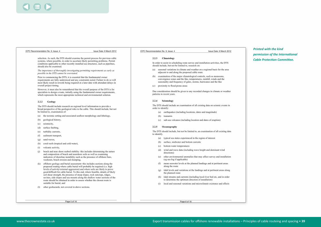
www.thecrownestate.co.uk Export transmission cables for offshore renewable installations – Principles of cable routeing and spacing • 39
ICPC Recommendation No. 9, Issue: 4 Issue Date: 6 March 2012
selection. As such, the DTS should examine the permit process for previous cable systems, where possible, in order to ascertain likely permitting problems. Permit conditions applicable to other recently installed sea structures, such as pipelines, should also be examined.
The importance of thoroughly investigating permitting requirements as early as possible in the DTS cannot be overstated. Prior to commencing the DTS, it is essential that the fundamental owner requirements are fully understood and any constraints noted. Failure to do so will most likely result in rework being required at a later date with attendant delays in overall project timing.
However, it must also be remembered that the overall purpose of the DTS is for specialists to design a route, initially using the fundamental owner requirements, which represents the most appropriate technical and environmental solution.
2.2.2 Geology
The DTS should include research on regional level information to provide a broad perspective of the geological risks to the cable. This should include, but not be limited to, examination of:
(a) the tectonic setting and associated seafloor morphology and lithology,
(b) geological history,
(c) seismicity,
(d) surface faulting,
(e) turbidity currents,
(f) sediment transport,
(g) sand waves,
(h) coral reefs (tropical and cold water),
(i) volcanic activity,
(j) beach and near shore seabed stability: this includes determining the nature and composition of beach and nearshore soils as well as examining indicators of shoreline instability such as the presence of offshore bars, washouts, beach erosion and slumping,
(k) offshore geology and burial assessment: this includes sections along the proposed routing where cable burial will probably be required (i.e. high levels of activity/external aggression) and where soils are likely to prove good/difficult for cable burial. To this end, where feasible, details of likely soil shear strength, the presence of steep slopes, rock outcrops, ridges, ravines, side slopes and sea mounts along the shallow water sections of the route should be obtained in order to assess whether the chosen route is suitable for burial, and
(l) other geohazards, not covered in above sections.
Page 5 of 16
ICPC Recommendation No. 9, Issue: 4 Issue Date: 6 March 2012
2.2.3 Climatology
In order to assist in scheduling route survey and installation activities, the DTS should include, but not be limited to, research on:
(a) seasonal variations in climate and weather on a regional basis for the area adjacent to and along the proposed cable route
(b) examination of the major climatological controls, such as monsoons, convergence zones and the like, temperatures, rainfall, winds and the seasonality and frequency of gales, storms, hurricanes and the like
(c) proximity to flood prone areas
Due consideration should be given to any recorded changes in climate or weather patterns in recent years.
2.2.4 Seismology
The DTS should include an examination of all existing data on seismic events in order to identify:
(a) earthquakes (including locations, dates and magnitude)
(b) tsunamis
(c) sub-sea volcanos (including location and dates of eruption)
2.2.5 Oceanography
The DTS should include, but not be limited to, an examination of all existing data to identify.
(a) typical sea states experienced in the region of interest
(b) surface, midwater and bottom currents
(c) bottom water temperatures
(d) wind and wave data (including wave height and dominant wind directions)
(e) other environmental anomalies that may affect survey and installation (eg sea fog if applicable)
(f) mean seawater levels at the planned landings and at pertinent areas along the route
(g) tidal levels and variations at the landings and at pertinent areas along the planned route
(h) tidal streams and currents (including local river bed etc, and in order to determine the optimum direction of installation)
(i) local and seasonal variations and microclimate existence and effects
Page 6 of 16
Printed with the kind permission of the International Cable Protection Committee.

www.thecrownestate.co.uk Export transmission cables for offshore renewable installations – Principles of cable routeing and spacing • 40
ICPC Recommendation No. 9, Issue: 4 Issue Date: 6 March 2012
2.2.6 Commercial Operations, Restricted Areas and Obstructions
The DTS should examine all existing information pertaining to existing or planned commercial operations, restricted areas and obstructions in the vicinity of the proposed cable route and landings. The factors to be addressed should include, but not be limited to:
(a) General shipping patterns (including shipping lanes and anchorage areas),
(b) Restricted areas (full-time or part-time) such as;
• anchorages,
• mined areas,
• military exercise areas,
• controlled shipping channels,
• dumping grounds (chemical/industrial wastes, explosives, radioactive materials) either in use, abandoned or planned,
• protected areas such as coral reefs (including cold water corals*), marine sanctuaries and national parks (it is imperative that landing area seasonal constraints due to nesting birds and animals, migrating whales and dolphins, schooling fish, etc are thoroughly investigated),
• culturally significant sites and
• tourist attractions * Note: UNEP (United Nations Environment Program) have advised the ICPC that cold-water corals thrive in water temperatures between 4°C and 13°C. The ICPC have agreed with UNEP that it would be very useful if submarine cables could be included as one of the layers in UNEP-WCMC IMAPS (Interactive Map Services). This would help to identify those areas where submarine cables and coral reefs are in close proximity. IMAPS is an openly accessible resource that can be found at: http://www.unep-wcmc.org/imaps/imaps_index.htm
(c) Commercial and Research activities such as;
• commercial fishing activities (current and future),
• offshore petroleum leases (current and future) that may require the construction of in-field or platform to shore transmission pipelines or umbilicals,
• pipelines (current and planned),
• other submarine cables (out-of-service and in-service, both current and planned in the vicinity of the proposed route) and their fault history, with tabulated information on the crossed systems name, cable type, position, water depth and angle at the crossing point and, where possible, distance to the crossed systems underwater plant, (i.e. repeaters and equalisers),
• plans to remove existing out-of-service submarine cables,
• fish aggregation devices,
Page 7 of 16
ICPC Recommendation No. 9, Issue: 4 Issue Date: 6 March 2012
• oceanographic and weather buoys,
• dredging activities,
• submarine resource development (including deep sea mining and Renewable energy), and
• coastal construction projects such as new port facilities, outfalls and intake structures
(d) Other obstructions such as shipwrecks, artificial reefs and the like
(e) Known security threats and piracy, or political groups that may pose security risks (including ‘non friendly’ countries or unstable governments)
It is important that the DTS database/basemap and subsequent survey database/basemap should be updated to cover these areas in an appropriate GIS (Geographical Information System) format with clear reference to source and date. This is to ensure that if the DTS Author and Survey Contractor obtain different information the survey contractor can easily check sources from the DTS against existing knowledge and ensure there is no missing, out of date or conflicting data.
2.2.7 Biological Factors
The DTS should examine all information pertaining to biological factors that could have an impact on the proposed cable project. These factors include, but are not limited to:
(a) flora and fauna (particularly threatened, endangered or protected species) located at the proposed landings
(b) seabed communities including shellfish, crustaceans and coral
(c) fish and shellfish spawning grounds and nursery areas
(d) local and migratory bird populations
(e) marine mammals and turtles
2.2.8 Regulatory Factors
The DTS should carefully examine and provide information about the laws and regulations of the region such as:
(a) limits of national/territorial waters (TW), Contiguous Zone (CZ) and Exclusive Economic Zone (EEZ), as applicable, and details of disputed waters and maritime boundaries, and marine sanctuaries, where relevant
(b) statutory requirements for both marine and land based activities such as environmental studies and reports, permits (installation and operating), notice to mariners, fishery seasonal restrictions, visas, equipment importation etc, which should be both described and summarised in a permit matrix or table for ease of reference
Page 8 of 16
Printed with the kind permission of the International Cable Protection Committee.
www.thecrownestate.co.uk Export transmission cables for offshore renewable installations – Principles of cable routeing and spacing • 41
ICPC Recommendation No. 9, Issue: 4 Issue Date: 6 March 2012
2.3 Site Visit
The DTS shall include reports of site visits to the primary Landing Points as well as, where possible/practical, alternate Landing Points. The site visit(s) shall examine;
(a) the existing infrastructure for landing and terminating a submarine cable
(b) suitable locations to land the submarine cable and construct new suitable landing facilities (for example beach manholes, system earthing facilities and ducts), if no existing infrastructure exists (include lat/long positions and photographs of the area in the DTS report)
(c) existing utilities that may conflict with proposed routing
(d) the geology to provide a geotechnical analysis of the landing sites which will aid in the design, construction or improvement of any proposed landing facilities
(e) shore end protection measures required (i.e. articulated pipe, directional drilling etc)
(f) marine and terrestrial constraints, that may determine whether the cable landing is to be direct from the main lay cableship or a separate shore end installation
(g) security issues that may constrain operations at the proposed landing
(h) the climate and weather and its potential impact on the construction, durability and landing of the cable into any proposed landing facilities
(i) all environmental aspects, both natural and man-made, which will impact on or be impacted by the implementation of any proposed landing facilities and the subsequent installation of the cable system
(j) all local organisations and authorities, including local fishing organisations, that will need to be liaised with during the planning, construction and operation of any proposed landing facilities and the installation, operation and maintenance of the cable system on both the land and marine routes within the Territorial Waters and possibly Exclusive Economic Zone (EEZ) or Continental Shelf of each landing site
(k) conditions applicable to permits for previous cable systems installed at each Landing Point and assess their relevance to the proposed cable system
(l) information on other seabed users and interested parties who could potentially oppose a permit application at a specific Landing Point and the stance that such groups could be expected to take
The DTS should also include a Shore End Landing Site Inspection report that should, as a minimum, include such data as:
Page 9 of 16
ICPC Recommendation No. 9, Issue: 4 Issue Date: 6 March 2012
(m) area, site and beach descriptions (of all alternate landings investigated)
(n) site accessibility (roadway width, surface, etc)
(o) working space assessments
(p) tides, weather, sea, swell information
(q) potential for beach erosion during severe storms
(r) marine traffic and fishing activity
(s) beach utilisation by public (and implications of applying access restrictions during laying operations)
(t) communications (radio permits, cell phone/mobile signal strengths)
(u) local facilities (civil contractor availability, shore end support, divers, hotels, etc)
(v) general facilities (airport, taxis, local ports, truck hire, etc)
(w) initial assessment on availability of locally chartered survey vessels and diving contractors
(x) identification of potential local shipping agents
It is recommended the DTS Contractor, the Supplier and the Purchasers Representative should all be present during site visits where practicable.
2.4 Route Recommendation
Based on the information acquired from the site visits and desktop investigative work the DTS shall recommend at least one appropriate cable route which, to the extent feasible, avoids any hazards and meets the cable burial requirements.
The recommended route should ensure that crossings of existing pipelines and cables follow applicable ICPC Recommendations as well as consider the future maintenance of the planned cable as well as existing or planned infrastructure.
The DTS should also provide a proposed route position list (RPL) and, where possible, a Straight Line Diagram (SLD).
The route recommendations should include, but not be limited to the following details:
(a) route position shown in latitude and longitude based on WGS84
(b) type of landing, such as, beach excavation or directional drilled conduits
(c) seabed depths
(d) initial cable engineering recommendations such as cable types and quantities, slack and definition of areas where cable should be buried for protection and the depth of burial
(e) route engineering recommendations resulting from, for example, slope angles, seabed feature avoidance, burial-ability, existing
Page 10 of 16
Printed with the kind permission of the International Cable Protection Committee.

www.thecrownestate.co.uk Export transmission cables for offshore renewable installations – Principles of cable routeing and spacing • 42
ICPC Recommendation No. 9, Issue: 4 Issue Date: 6 March 2012
regional fault history and alter course angles (which should ideally not exceed 25 degrees)
2.5 Survey Recommendation
The DTS shall provide recommendations for suitable terrestrial and marine surveys to accurately define the proposed route and for determining the precise route length, appropriate types and quantities of cable and installation and burial requirements.
The DTS shall provide, where possible, geodetic parameters, methodology and example computations of all transformations required to transform the proposed route WGS84 geographical co-ordinates into National Mapping Parameters for all landing sites and/or other appropriate areas as required by National Mapping Agencies/Government Organisations.
The recommendation should include, but not be limited to, the equipment and techniques required for the collection and collation of the following types of data:
(a) bathymetry
(b) seabed and sub-seabed features
(c) seabed temperatures
(d) ocean currents
(e) cable burial assessment (DTS to specify recommended equipment & techniques to be used, which should comprise a combination of geotechnical and geophysical equipment and techniques
(f) topographic and geotechnical data for each landing
(g) survey swathe widths
(h) areas on the route where further route development may be necessary during the survey
2.6 Reporting and Documentation
The DTS shall provide for the following reports.
2.6.1 Regular Status Reports
Regular Status Reports (timing to be agreed between contractor and client) should be provided to the client from the date of execution of the Contract up until the completion of the DTS. It is recommended that the Regular Status Reports should include, but not be limited to;
(a) current Plan of Work
(b) update on the progress of significant events such as site visits and the Desktop Study Report
(c) advice on the key issues noted during site visits or desktop research, which may impact on the choice of landings or routing of the proposed cable
Page 11 of 16
ICPC Recommendation No. 9, Issue: 4 Issue Date: 6 March 2012
(d) progress against the baseline plan of work, critical path items and any items that may impact finishing the DTS on schedule
2.6.2 The Preliminary Site Visit Report
The Preliminary Site Visit Report, if required by the client, should be provided to the client within the duration agreed between the contractor and client. (Note that it may be decided that the contents of such a Report be included within the DTS as per Section 2.3.)
If required, the Preliminary Site Visit Report shall include, but not be limited to;
(a) summary of observations with regard to the requirements listed above, including photographs, geo-referenced beach sketches and GPS measurements of proposed Beach Manhole position together with other salient features
(b) list of people and authorities, particularly local fishing organisations, visited and nature of discussions with or advice from these parties
(c) list of follow-on actions to be taken by as part of the desktop research
(d) list of recommended actions such as initiating environmental approvals with relevant local authorities
2.6.3 Desktop Study Report
The Desktop Study Report shall provide detailed information on all the issues specified above and shall be structured along the lines of the following format. Emphasis should be given to the provision of relevant maps, diagrams, charts, figures, tables and photographs in order to add clarity to the report.
(a) introduction
(b) executive summary (to include a tabulated Risk Analysis/Summary, which identifies mitigation recommendations, where necessary)
(c) detailed analysis of:
• routing selection and landings,
• permitting requirements
• geology,
• climatology
• seismology
• oceanography
• environmental and man-made factors
• fisheries
• biological factors
• regulatory factors
(d) burial assessment and estimated external aggression risk
Page 12 of 16
Printed with the kind permission of the International Cable Protection Committee.
www.thecrownestate.co.uk Export transmission cables for offshore renewable installations – Principles of cable routeing and spacing • 43
ICPC Recommendation No. 9, Issue: 4 Issue Date: 6 March 2012
(e) route recommendations (RPLs and SLDs etc)
(f) survey recommendations
(g) initial cable engineering recommendations
(h) relevant photographs, diagrams and charts
(i) list of all persons and organisations (plus contact details) consulted during the DTS
(j) bibliography of all research material and advice.
The report contents should include:
• all the information gathered during the desk study
• the provisional cable route in the form of both a physical description and route position list that has been developed during the initial conceptual system design and desk study phases of system planning. The provisional route would also be plotted on the system planning charts showing all route alter course points
• definition of provisional cable quantities and cable engineering including provisional cable armouring schemes.
• full detailed description of the cable landing sites including photographs and diagrams
• full details of route permitting issues and procedures including the status of routing negotiations (including contact details for the relevant entities, together with estimated times to obtain the various permits indicated wherever feasible
• definition of detailed route survey procedures and scope of work, which should be based on the most appropriate technical approach that addresses the prevailing physical conditions of the route and the cable protection and installation strategies, recommended in the report
2.6.4 DTS Report Database and Basemap
All database information should be collated into the DTS basemap in an appropriate GIS format with clear reference to source and date. This should then be passed on to the Survey Contractor in a timely manner to allow the cross checking of sources from the DTS against existing knowledge and ensure there is no missing, out of date or conflicting data.
2.6.5 Digital Format of DTS Report
The Desktop Study Report shall be provided in a digital version, including all text, tables, photographs and diagrams. Consideration should be given to producing digital copies, including photographs, drawings, etc. in a machine independent universal platform such as Adobe’s Acrobat™ software. Database and spreadsheet items should also be provided in ODBC (Object Database Connectivity) compliant formats such as Access™, Excel™ and Lotus™.
Page 13 of 16
ICPC Recommendation No. 9, Issue: 4 Issue Date: 6 March 2012
The ideal platform for displaying and manipulating diverse datasets simultaneously (as well as being a data management system) is a GIS system that does not rely on data transfer to software specific formats. Such GIS systems should be able to read/write ODBC, SQL and Oracle™ databases and related data items. The digital copies should be provided on CD-ROM or DVD format which can be read using any IBM™ compatible PC equipped with the above mentioned software.
2.6.6 DTS Report Quantities
It is recommended that consideration be given to the requirements of the cable system supplier when determining the required number of copies of each DTS report.
2.7 Charting Requirements
2.7.1 Description
The DTS shall include a series of north up, adjoining, overlapping charts which should include data presentations showing the proposed cable route, bathymetry contours, geologic interpretations (particularly in areas of proposed burial), existing cables and other pertinent features. Any features identified on the charts shall be annotated in terms of scale, composition and with an appropriate interpretation. The charts should exhibit the following features:
(a) All charts should show latitude and longitude, graduated in degrees, minutes and decimal minutes. It is recommended that Mercator Projection charts are used for overview and long line segments whilst Universal Transversal Mercator and Lambert Conformal Conic Projections are used for detail and short leg charts. Note that in some areas, such as Landings, the charts of the cable route may also be required in the National Mapping Projections and Spheroids required for the particular location. Wherever possible, however, one projection should ideally be used throughout the DTS to avoid complications and confusion arising from datum transformations.
(b) Each chart shall have appropriate title boxes on each of its co-registered parts. Each title box shall include at least:
• Title (including cable system name and landing points) • Projection• Central meridian specific to that chart • Datum • Scale presented as both a representative fraction and as a linear
scale in kilometres (km) • Chart production date • Project identification • Chart key including a suitably scaled overview of the geographic
region and the locations of bordering charts. The chart key shall also show the geographic limits of the specific chart
• Chart notes
Page 14 of 16
Printed with the kind permission of the International Cable Protection Committee.

www.thecrownestate.co.uk Export transmission cables for offshore renewable installations – Principles of cable routeing and spacing • 44
ICPC Recommendation No. 9, Issue: 4 Issue Date: 6 March 2012
• Chart legend • Names of Purchasers • Contractor's name and contact details • A separate chart(s) of the landing that shall identify navigational
and other information pertinent to the anchoring/cable landing operations shall be provided. These charts shall extend to at least the 20m water depth and include nearby terrestrial landmarks that may be of assistance in positioning the ship while the cable "shore-end" is landed.
2.7.2 Chart Scales
Recommended chart scales required for various regions along the route are summarised in the table below. Specific requirements should be agreed between the DTS contractor and client prior to contract signing.
Zone Chart Scale
(a) Overview chart for the whole route Best Fit
(b) A series of charts for the whole route 1:500,000(to a minimum of 1:100,000 as appropriate in order to identify bathymetric features)
(c) Terminal site to 20 metres water depth 1:20,000(including landfall sketch map, at any scale)
(d) Remainder of continental shelf 1:100,000
The scales here are a recommendation only. In areas where more detail is available scales should be adjusted to maximise the data presented.
Page 15 of 16
ICPC Recommendation No. 9, Issue: 4 Issue Date: 6 March 2012
3. REFERENCES Document Number TitleICPC Recommendation No 2 Recommended Routing & Reporting Criteria For
Cables in Proximity to Others
4. DEFINITIONS
The following words, acronyms and abbreviations are referred to in this document.
Term DefinitionCD-ROM Compact Disc-Read Only Memory
DTS Desktop Study (also known as a Cable Route Study)
DVD Digital Versatile Disc
GIS Geographical Information System
GPS Global Positioning System
PC Personal Computer
RPL Route Position List
SLD Straight Line Diagram
WGS84 World Geodetic System 1984
5. ATTACHMENTS Document Number TitleNil
6. ACKNOWLEDGEMENTS This document has been produced with the kind assistance of the Submarine Cable Improvement Group (http://www.scig.net/) and representatives from the Marine Survey Industry.
Page 16 of 16
Printed with the kind permission of the International Cable Protection Committee.

www.thecrownestate.co.uk Export transmission cables for offshore renewable installations – Principles of cable routeing and spacing • 45
Page 1 of 4
LOSS PREVENTION BULLETIN
18 March 2009
Damage to Submarine Cables Caused by AnVessel o s could
aults to submarine cables around the world has been closely monitored since the
use Percentage
LOSS PREVENTION BULLETIN
18 March 2009
Damage to Submarine Cables Caused by AnVessel o s could
aults to submarine cables around the world has been closely monitored since the
use Percentage
chors chors wners are recognising that costly damage to submarine communications cablewners are recognising that costly damage to submarine communications cable
be prevented by securing anchors more diligently before a vessel gets underway. New information about causes of cable breaks shows that dragging anchor while under way is a more common cause of damage than previously believed. The vessels at fault are identified using AIS and their owners are likely to be charged with losses sustained by the cable owner. However all cable owners recognise that preventing these incidents in the first place is in everyoneʼs interest, hence the purpose of this ICPC Bulletin.
Background
The cause of fThe cause of fformation of the International Cable Protection Committee (ICPC) in 1958. Since then the general consensus within the submarine cable industry has been that the majority of faults are caused by fishing - Table 1 refers:
Ca
formation of the International Cable Protection Committee (ICPC) in 1958. Since then the general consensus within the submarine cable industry has been that the majority of faults are caused by fishing - Table 1 refers:
CaFishing 67%Anchors 8%Dredging 2%
Other 23%
Table 1 – ine Cable fault distr to 2006
In 2006 the first Autom d by BT (a submarine
ty
een aware of the risk of damage to submarine cables due to vessels dragging whilst at anchor and some cable owners provide overlays for port radars that show the location
Submar ibution
atic Identification System (AIS) aerial was erectecable owner and ICPC Member) in the South West of the UK and provided the means for monitoring the position of vessels over 300 gross tonnes. In the event of a cable fault this cable owner was able to match the time and position of the failure with vessel data from AIS and determine if there was a correlation. This enhancement in root cause analysis is causing the submarine cable industry to reconsider its thinking on the probable cause of many submarine cable faults.
Port Proximi
The ICPC has b
of submarine cables. Some of these owners have also started to use AIS to provide early warning of when a vessel is likely to be dragging at anchor and approaching a submarine cable, however such use of AIS is not yet widespread. During the early part of 2008 a number of incidents of vessels' anchors causing damage to submarine cables were documented both in waters around the UK and elsewhere in the world. An example is shown in MARS 200840 - Attachment 1 refers.
Vessels Underway
Page 2 of 4
The use of AIS has proved invaluable in determining the cause of some submarine cable faults d the extent of faults caused by the anchors of vessels that are underway.
Since 2006 cable owners have observed 21 submarine cable faults around the UK alone. As and has also reveale
can be seen in Table 2, the causal distribution has changed significantly:
Cause Pre 2007 2007 - 2008 Fishing 67% 33%Anchors 8% 48% D redging 2% 0%
Other 23% 19%
Table 2 – Submarine e fault distribution
There were 10 cases of anchor damage to submarine cables and all involved vessels that had been underway with their ls also damaged multiple cables during the same event.
lly be localised by a typical deformation of the armour wires but the strain induced can cause damage for hundreds of metres in both directions. The typical
Cabl
anchors deployed. Some of these vesse
The damage to a submarine cable by an anchor can be evidenced over an extended length of cable. The point of contact can usua
result of anchor damage to a submarine cable is shown below:
In all of the cited examples of damage to a submarine cable by a vesselʼs anchor, the cable owners are either in correspondence or have agreed compensation ith the vesselʼs surveyors and P&I Club members. Many cable owners have received compensation for damage to their
hilst underway. The ICPC therefore urges all vessel owners to be vigilant in ensuring that their anchors are securely stowed prior to passage.
rs prior to sea passage – Attachment 2 refers.
w
submarine cables caused by anchors. If settlement is not forthcoming, cable owners have a reputation for obtaining compensation for their losses and damages can easily exceed US$1M per incident.
The ICPCʼs members are working with the shipping industry to prevent vesselsʼ anchors from ʻrunning-outʼ w
Mars 200836 is a very helpful reference for vessel owners because it recommends the minimum precautions to be taken by ships personnel for securing ancho
Appendix 4 – ICPC loss prevention bulletin
Printed with the kind permission of the International Cable Protection Committee.
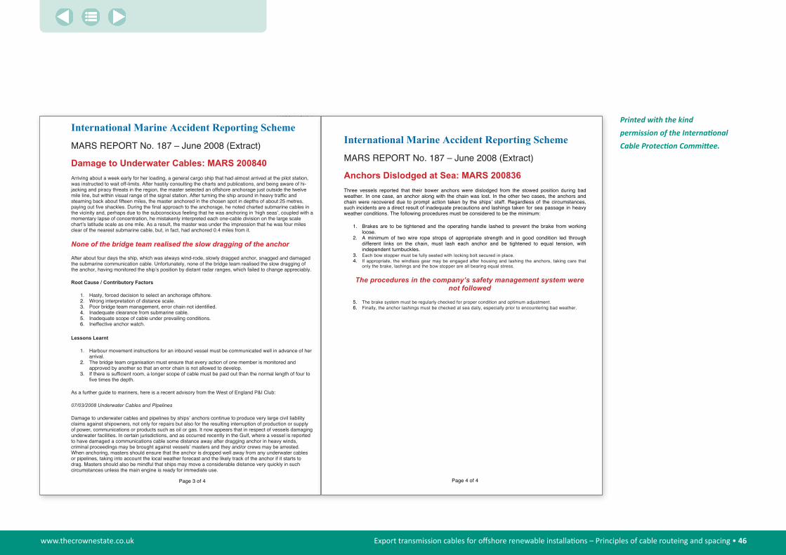
www.thecrownestate.co.uk Export transmission cables for offshore renewable installations – Principles of cable routeing and spacing • 46
Attachment 1
Page 3 of 4
RT No. 187 – June 2008 (Extract)
Damage to Underwater Cables: MARS 200840 Arriving about a week early for her loading, a general cargo ship that had almost arrived at the pilot station, was instructed to wait off-limits. After hastily consulting the charts and publications, and being aware of hi-jacking and piracy threats in the region, the master selected an offshore anchorage just outside the twelve mile line, but within visual range of the signal station. After turning the ship around in heavy traffic and steaming back about fifteen miles, the master anchored in the chosen spot in depths of about 25 metres, paying out five shackles. During the final approach to the anchorage, he noted charted submarine cables in the vicinity and, perhaps due to the subconscious feeling that he was anchoring in ʻhigh seasʼ, coupled with a momentary lapse of concentration, he mistakenly interpreted each one-cable division on the large scale chartʼs latitude scale as one mile. As a result, the master was under the impression that he was four miles clear of the nearest submarine cable, but, in fact, had anchored 0.4 miles from it.
None of the bridge team realised the slow dragging of the anchor
After about four days the ship, which was always wind-rode, slowly dragged anchor, snagged and damaged the submarine communication cable. Unfortunately, none of the bridge team realised the slow dragging of the anchor, having monitored the shipʼs position by distant radar ranges, which failed to change appreciably.
Root Cause / Contributory Factors
1. Hasty, forced decision to select an anchorage offshore. 2. Wrong interpretation of distance scale.3. Poor bridge team management, error chain not identified.4. Inadequate clearance from submarine cable.5. Inadequate scope of cable under prevailing conditions.6. Ineffective anchor watch.
Lessons Learnt
1. Harbour movement instructions for an inbound vessel must be communicated well in advance of her arrival.
2. The bridge team organisation must ensure that every action of one member is monitored and approved by another so that an error chain is not allowed to develop.
3. If there is sufficient room, a longer scope of cable must be paid out than the normal length of four to five times the depth.
As a further guide to mariners, here is a recent advisory from the West of England P&I Club:
07/03/2008 Underwater Cables and Pipelines
Damage to underwater cables and pipelines by shipsʼ anchors continue to produce very large civil liability claims against shipowners, not only for repairs but also for the resulting interruption of production or supply of power, communications or products such as oil or gas. It now appears that in respect of vessels damaging underwater facilities. In certain jurisdictions, and as occurred recently in the Gulf, where a vessel is reported to have damaged a communications cable some distance away after dragging anchor in heavy winds, criminal proceedings may be brought against vesselsʼ masters and they and/or crews may be arrested. When anchoring, masters should ensure that the anchor is dropped well away from any underwater cables or pipelines, taking into account the local weather forecast and the likely track of the anchor if it starts to drag. Masters should also be mindful that ships may move a considerable distance very quickly in such circumstances unless the main engine is ready for immediate use.
International Marine Accident Reporting Scheme
MARS REPO
Attachment 2
Page 4 of 4
cheme
d
,
g
through ion, with
t
company’s safety management system were not followed
n and optimum adjustment.cially prior to encountering bad weather.
International Marine Accident Reporting S
MARS REPORT No. 187 – June 2008 (Extract)
Anchors Dislodged at Sea: MARS 200836 Three vessels reported that their bower anchors were dislodged from the stowed position during baweather. In one case, an anchor along with the chain was lost. In the other two cases, the anchors andchain were recovered due to prompt action taken by the shipsʼ staff. Regardless of the circumstancessuch incidents are a direct result of inadequate precautions and lashings taken for sea passage in heavy weather conditions. The following procedures must be considered to be the minimum:
1. Brakes are to be tightened and the operating handle lashed to prevent the brake from workinloose.
2. A minimum of two wire rope strops of appropriate strength and in good condition leddifferent links on the chain, must lash each anchor and be tightened to equal tensindependent turnbuckles.
3. Each bow stopper must be fully seated with locking bolt secured in place.4. If appropriate, the windlass gear may be engaged after housing and lashing the anchors, taking care tha
only the brake, lashings and the bow stopper are all bearing equal stress.
The procedures in the
5. The brake system must be regularly checked for proper conditio6. Finally, the anchor lashings must be checked at sea daily, espe
Printed with the kind permission of the International Cable Protection Committee.

www.thecrownestate.co.uk Export transmission cables for offshore renewable installations – Principles of cable routeing and spacing • 47
Protection of a cable by means of burial can be seen as the most promising method of protection. The only parameter in the design of the burial protection is the burial depth. It has always been recognised that “stronger” seabed soils provide a greater protection than a “softer” soil for a cable buried to similar depth. In 1997 (Mole at al) the Burial Protection Index (BPI) was introduced to account for such soil characteristics. the chart produced by Mole et al is reproduced here. P. allen gave a further definition of the BPI in 1999.
BPI = 1 Depth of Burial consistent with protecting a able against normal fishing gear only. Would be appropriate to water depths greater than say 100m where anchoring of ships is unlikely, or in areas where shipping and anchoring is effectively prohibited.
1
2
3
0 20
1 3Burial Protec�on Index
Very So� Clay
Coarse sand Firm Clay
Fine Sand
bPi = 2 Depth of Burial will provide protection from vessels with anchors up to app. 2 tonnes. This may be adequate for normal fishing activities but would not be suitable for larger ships’ anchors.
bPi = 3 Depth of Burial sufficient to protect from anchors of all but the largest ships. Suitable for anchorages and heavily trafficked shipping channels with adjustments made to suit known ship/anchor sizes.
Above basis is used in the proposed protection design with necessary adjustments for the local conditions and method of burial and nature of any backfill soil.
Appendix 5 – Burial protection index
© RedPenguin

www.thecrownestate.co.uk Export transmission cables for offshore renewable installations – Principles of cable routeing and spacing • 48
4 References
“Round 3 Offshore Wind Farm Connection Study” – The Crown Estate.
“ICPC Recommendation No. 9 Minimum Technical Requirements for a Desktop Study (also known as Cable Route Study)” and “ICPC LOSS PREVENTION BULLETIN 18 March 2009” – Damage to Submarine Cables Caused by Anchors – Printed with the kind permission of the International Cable Protection Committee.
“Our Electricity Transmission Network – A Vision for 2020” – ENSG March 2009.
“Offshore Transmission Coordination Project Report” – Ofgem/DECC March 2012.
“2011 Offshore Development Information Statement” – ODIS September 2011.
“Guidance on the Decommissioning of Submarine Telecommunication Cable” – The Crown Estate February 2012.
“Review of Cabling Techniques and Environmental Effects applicable to the Offshore Wind Farm Industry” – BERR in association with Defra January 2008.
“Towards Round 3: Building the Offshore Wind Supply Chain”�– BVG Associates.
“EMF-sensitive fish response to EM emissions from sub-sea electricity cables of the type used by the offshore renewable energy industry” – Gill, A. B., Y. Huang, I. Gloyne-Phillips, J. Metcalfe, V. Quayle, J. Spencer, and V. Wearmouth. 2009.
“Submarine Power Cables – Design, Installation, Repair (and) Environmental Aspects” – Thomas Worzyk.
“Selecting Appropriate Cable Burial Depths – A Methodology” – P G Allan November 1998.
“The Minimum Technical Requirements for a Desk Top Study” – International Cable Protection Committee (ICPC) Recommendation No. 9 Issue 4 March 2012.
“The Threat of Damage to Submarine Cables by the Anchors of Ships Underway” – Mick Green and Keith Brooks.
“Cable Protection – Solutions through new installation and burial approaches” – P. Mole, J. Featherstone, S. Winter, SubOptic 1997 San Francisco.
“Effects of EMF’s from Undersea Power Cables on Elasmobranchs and other Marine Species” – US Bureau of Ocean Energy Management, Regulation and Enforcement September 2011.
“The environmental effects of the installation and functioning of the submarine SwePol Link HVDC transmission line: a case study of the Polish marine area of the Baltic Sea”�– Andrulewicz, E. D., D. Napierska, and Z. Otremba. 2003.
“Offshore Grid: Offshore Electricity Infrastructure in Europe”�– EWEA October 2011.
“Offshore Transmission Network Feasibility Study” – The Crown Estate/National Grid September 2011. ©
Offs
hore
Mar
ine
Man
agem
ent