explosive fracturing of an f-16 canopy for … · explosive fracturing of an f-16 canopy for...
TRANSCRIPT

EXPLOSIVE FRACTURING OF AN F-16 CANOPY
FOR THROUGH-CANOPY CREW EGRESS
BY
Laurence J. Bement
NASA Langley Research Center
Presented at the
The 38 th Annual SAFE Symposium
October 9-11, 2000
Reno, Nevada
https://ntrs.nasa.gov/search.jsp?R=20000109968 2018-06-05T16:15:59+00:00Z
EXPLOSIVEFRACTURINGOF AN F-16CANOPYFORTHROUGH-CANOPYCREWEGRESS
by
LaurenceJ.BementNASA LangleyResearchCenter
ABSTRACT
Through-canopycrewegress,suchasin theHarrier(AV-8B) aircraft,expandsescapeenvelopesby reducingseatejectiondelaysin waiting for canopyjettison. Adverseaircraftattitudeandreducedforwardflight speedcanfurtherincreasethetimesfor canopyjettison. However,theadventof heavy,high-strengthpolycarbonatecanopiesfor bird-strikeresistancehasnot onlyincreasedjettison times,buthasmadeseatpenetrationimpossible.Thegoalof theeffortdescribedin thispaperwasto demonstratea methodof explosivelyfracturingtheF-16polycarbonatecanopyto allow through-canopycrewejection. Theobjectivesof this effort wereto: 1.Mount theexplosivematerialsontheexteriorof thecanopywithin themold line, 2.Minimize visualobstructions,3. Minimize internaldebrisonexplosiveactivation,4. Operatewithin lessthan10ms,5. Maintaintheshapeof thecanopyafter functioningto preventmajorpiecesfrom enteringthecockpit,and6. Minimize theresistanceof thecanopyto seatpenetration.All goalsandobjectivesweremet in afull-scaletestdemonstration.In additiontoexpandingcrewescapeenvelopes,thiscanopyfractureapproachoffersthepotentialfor reducingsystemcomplexity,weightandcost,while increasingoverallreliability, comparedto currentcanopyjettisonapproaches.
To complywith InternationalTraffic in Arms Regulations(ITAR) andpermitpublic disclosure,this documentaddressesonly theprinciplesof explosivefracturingof theF-16canopymaterialsandtheendresult. ITAR regulationsrestrictinformationon improvingtheperformanceofweaponsystems.Therefore,detailsontheexplosiveloadsandfinal assemblyof this canopyfractureapproach,necessaryto assurefunctionalperformance,arenot included.
INTRODUCTION
Manycurrentfighteraircraftusecanopyjettisonapproachesto clearanuninhibitedpathfor crewegress.Thisapproachusespyrotechnic(explosiveor propellant-actuated)devicesto firstactivatelatchreleasemechanismsto freethecanopyassemblyfrom theairframe,andthenjettisontheassemblywith piston/cylinderthrustersor smallrocketmotorsmountedat theforwardedgeof theassembly.Thecanopypivotsaroundaft hingepoints. Seatejectioncatapultsarenot initiateduntil thecanopyhaspivotedfar enoughto insurethattheseatandcanopywill notcollide. How quickly thecanopyassemblyisjettisoneddependsonaircraftattitudeandforwardvelocity. A pitch-downattitudewith a flight vectorto producea loadon the

canopywould resistjettison. Also, if theaircrafthasalow forwardvelocity, therewouldbeaminimal aerodynamicassiston thecanopy. Someaircraft,suchastheF-15,employabackupapproachto canopyjettison byusingfrangibleacryliccanopiesanddesigningtheseatto "punchthrough"to insureegress.The Harrier (AV-8B) aircraft, a vertical takeoff and landing aircraft,
utilizes an interior-mounted explosive cord to fracture acrylic canopies to assure an immediately
available, unrestricted through-canopy egress path to reduce crew ejection time. However, on
activation, this explosive cord creates explosive pressure waves and peppers the crew with high-
velocity fragments from the explosive's metal sheath and from the 3/8th-inch width explosive
holder. The crewmembers also face potential harm from the fractured pieces of canopy material.
Canopy jettison approaches introduce a higher degree of complexity over through-canopy egress.
The advent of using polycarbonate canopies to resist bird strikes eliminated the possibility of
either "punching through" the canopy or applying the Harrier approach. However, current
projections of thickness and weight of these canopies indicate that thrusters and rocket motor
jettison approaches are reaching capability limits. Furthermore, canopy release and jettison
approaches require 3 to 4 mechanisms, such as latch actuators, thrusters and rocket motors. For
redundancy, each of these mechanisms requires two inputs.
A reliable method of severing polycarbonate to allow through-canopy crew egress would reduce
egress time to expand escape envelopes, simplify aircraft systems and potentially reduce system
weight.
The goal of the effort described in this paper was to demonstrate a method of explosively
fracturing the half-inch thick polycarbonate portion of the F-16 canopy to allow through-canopy
crew egress.
The objectives for canopy fracturing were to:
1. Mount the explosive materials on the exterior of the canopy within the mold line2. Minimize visual obstructions
3. Minimize internal debris on explosive activation
4. Operate within 10 ms (the seat requires at least 30 milliseconds from catapult initiation to
reach the canopy)
5. Maintain the shape of the canopy after functioning to prevent major pieces from entering the
cockpit6. Minimize the resistance of the fractured canopy to seat penetration
The approach for this development, initiated in references 1, 2 and 3, was to utilize augmented
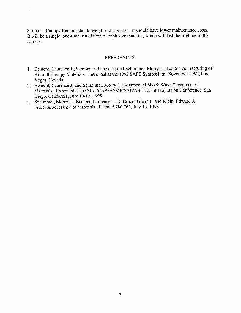
shock wave severance principles. Parallel explosive cords, as shown in figure 1 in which the
cords are proceeding into the plane of the paper, are initiated simultaneously. The several-
million psi pressure generated by the explosive cords transfers into the polycarbonate and the
resulting incident and reflected explosive pressure waves augment to induce the material to fail
in tension. The preliminary effort began with evaluations on commercial grade polycarbonate.
Then the F-16 canopy was selected for evaluation, since it is the first production polycarbonate
canopy, and service-scrapped canopies were available. Small (6 X 6-inch plate) specimens were
cut from flat stock and canopies for testing. The evaluation progressed to small-scale (18 to
30-inchdimension),"mini-panels"to determinetheperformanceof completefracturepatterns.Finally,threefull-scalecanopytestswereconducted.
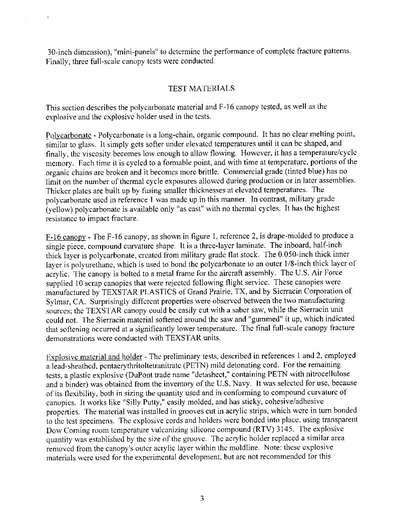
TESTMATERIALS
ThissectiondescribesthepolycarbonatematerialandF-16canopytested,aswell astheexplosiveandtheexplosiveholderusedin thetests.
Polycarbonate - Polycarbonate is a long-chain, organic compound. It has no clear melting point,
similar to glass. It simply gets softer under elevated temperatures until it can be shaped, and
finally, the viscosity becomes low enough to allow flowing. However, it has a temperature/cycle
memory. Each time it is cycled to a formable point, and with time at temperature, portions of the
organic chains are broken and it becomes more brittle. Commercial grade (tinted blue) has no
limit on the number of thermal cycle exposures allowed during production or in later assemblies.
Thicker plates are built up by fusing smaller thicknesses at elevated temperatures. The
polycarbonate used in reference 1 was made up in this manner. In contrast, military grade
(yellow) polycarbonate is available only "as cast" with no thermal cycles. It has the highest
resistance to impact fracture.
F-16 canopy - The F-16 canopy, as shown in figure 1, reference 2, is drape-molded to produce a
single piece, compound curvature shape. It is a three-layer laminate. The inboard, half-inch
thick layer is polycarbonate, created from military grade flat stock. The 0.050-inch thick inner
layer is polyurethane, which is used to bond the polycarbonate to an outer 1/8-inch thick layer of
acrylic. The canopy is bolted to a metal frame for the aircraft assembly. The U.S. Air Force
supplied 10 scrap canopies that were rejected following flight service. These canopies were
manufactured by TEXSTAR PLASTICS of Grand Prairie, TX, and by Sierracin Corporation of
Sylmar, CA. Surprisingly different properties were observed between the two manufacturing
sources; the TEXSTAR canopy could be easily cut with a saber saw, while the Sierracin unit
could not. The Sierracin material softened around the saw and "gummed" it up, which indicated
that softening occurred at a significantly lower temperature. The final full-scale canopy fracturedemonstrations were conducted with TEXSTAR units.
Explosive material and holder - The preliminary tests, described in references 1 and 2, employed
a lead-sheathed, pentaerythritoltetranitrate (PETN) mild detonating cord. For the remaining
tests, a plastic explosive (DuPont trade name "detasheet," containing PETN with nitrocellulose
and a binder) was obtained from the inventory of the U.S. Navy. It was selected for use, because
of its flexibility, both in sizing the quantity used and in conforming to compound curvature of
canopies. It works like "Silly Putty," easily molded, and has sticky, cohesive/adhesive
properties. The material was installed in grooves cut in acrylic strips, which were in turn bonded
to the test specimens. The explosive cords and holders were bonded into place, using transparent
Dow Corning room temperature vulcanizing silicone compound (RTV) 3145. The explosive
quantity was established by the size of the groove. The acrylic holder replaced a similar area
removed from the canopy's outer acrylic layer within the moldline. Note: these explosive
materials were used for the experimental development, but are not recommended for this
application,dueto a relativelylow meltingpointandthermalstability. Other,morestablematerialsareavailable.
Explosive pattern - As shown in figure 2, the layout (grooves) for the explosive severance pattern
for the first full-scale test was on the top centerline, forward and aft of crewmember, and around
the lower extremity. The goal was to create a "French-door" opening. The initiation sites (2 for
redundancy) were located at aft hinge points, which also is the closest access between the canopy
and aircraft with the canopy open. On initiation, the explosive propagates upward and forward
from these sites at a velocity of 22,000 feet/second. Common initiation points at intersections
must be used to assure that the explosive propagation fronts remain in parallel to maintain shock
wave augmentation for long-length applications.
FULL-SCALE TEST DEVELOPMENT PROCEDURE
The development proceeded from small plates to panels to the full-scale canopy.
Small plates - References 1 and 2 describe tests on small (6 X 6-inch) plates cut from
commercial and military grade polycarbonate stock, as well as from F-16 canopies. The plates
were tested with two edges clamped to simulate conditions within the canopy.
Panels - The same references also describe "mini-panel" tests with which experiments were
conducted to determine the performance of the "French-door" severance pattern and of crack
propagation. Explosive patterns were placed close to the edges of the panel. Additional mini-
panel tests were conducted in which the panel was framed by 1/8th-inch skin thickness aluminum
to simulate the stiffness afforded by the aircraft installation. Also, tests were conducted where
the explosive patterns were placed well away from the edge of the panel.
Full-scale tests - All three tests were documented with high-speed video cameras.
The first test, as described in reference 2, used 2 lead-sheathed explosive cords that were placed
in grooves cut into the exterior layer of acrylic in the pattern shown in figure 1. The cords were
bonded into place with RTV-3145. The canopy was placed, unsupported, on a flat surface as
shown in the figure. The ambient temperature was approximately 75 o F.
The second test was conducted with two grooves cut into separate acrylic strips, filled with
plastic explosive, and installed into slots from which the acrylic was removed from the canopy.
The strips were bonded to the canopy using RTV-3145. Prior to installation of these strips, the
0.050-inch thick polyurethane middle layer was cut with a razor blade to negate its post-fire
residual strength. Modified explosive patterns were used at the intersection sites of the
severance paths. The objective was to independently sever these sites to allow end-to-end crack
propagation. Again the canopy was unsupported on a flat surface. The ambient temperature was
approximately 90 ° F.
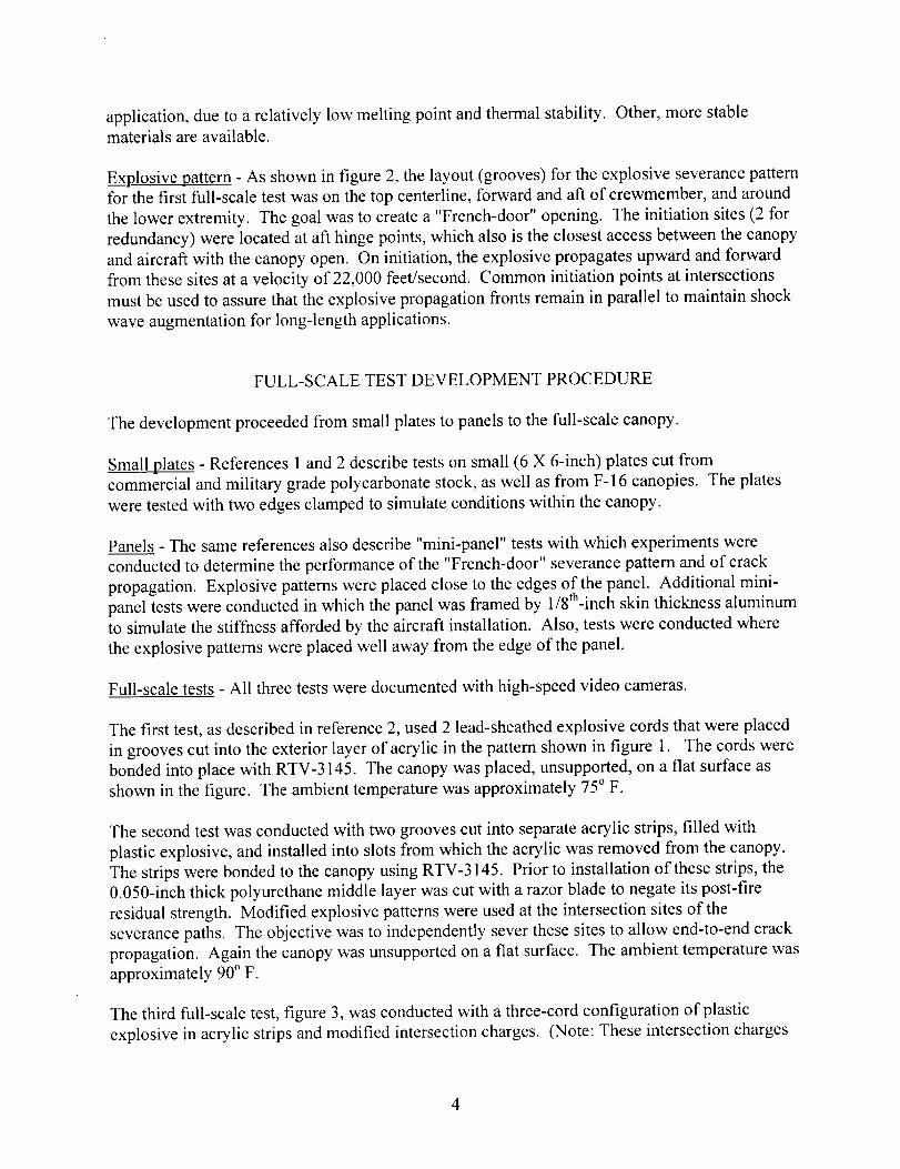
The third full-scale test, figure 3, was conducted with a three-cord configuration of plastic
explosive in acrylic strips and modified intersection charges. (Note: These intersection charges
4
havebeenmaskedto meetITAR regulations.)Prior to installationof thesestrips,usingRTV-3145asabondingagent,the0.050-inchthickpolyurethanemiddle layerwascut with arazorbladeto negateits post-fireresidualstrength.To simulatetheaircraft installation,thecanopywasfastenedto arigid frame. Thecanopywasattachedto woodenbeamsthatwerecontouredto fit the interiorof thecanopy-mountinginterface.Thebeamswerethenfastenedtoasheetof 3/4-inchplywood. Thetestwasconductedat approximately85degrees.
TESTRESULTS
Small plates - The small-plate tests (references 1 and 2 and figure 1) revealed that the
commercial grade polycarbonate in thicknesses to 1 inch were easily fractured with the two-cord
explosive arrangement. However, the same test configurations had little effect on military grade
material. A 0.063-inch thickness layer of polyurethane, between the explosive and
polycarbonate, was required to efficiently couple explosive shock waves to sever a 0.9-inch
thickness, military grade plate. In all small-plate tests (F-16 and military grade plate stock), this
polyurethane inner-layer remained completely intact after the explosive firing.
Panels - The mini-panel tests were much simpler and less expensive than full-scale tests. The
tests conducted with both lead-sheathed explosive cords, references 1 and 2, and subsequently
with plastic explosive in acrylic holders, exhibited completely successful explosive propagation.
The panel tests were somewhat misleading. The small, relatively flat panels were able to flex
inboard on the desired cutting planes to provide an additional tensile force on the interior surface.
Also, since the explosive patterns were close to the edges of the panels, internally initiated cracks
easily propagated across the panel. However, subsequent tests with an aluminum frame and
highly curved sections, which stiffened the panel, and with the explosive patterns placed at least
6 inches from the edge of the panel, complete severance could not be achieved. Tests with
additional charges at the pattern intersections "punched out" those sites. Tests on highly
contoured, stiff canopy sections, with a 3-cord explosive pattern and with the ends of the pattern
free, achieved complete severance. Finally, it was observed that the 0.050-inch thick
polyurethane middle layer, which remained completely intact after the explosive firing had
considerable residual strength.
Full-scale tests - The assembly of the explosive into the canopy in all three tests was completely
successful. No explosive propagation failures occurred. These tests also demonstrated that the
acrylic strips could replace the outer layer of protective acrylic in the canopy installation.
In the first test (reference 2), approximately 9% of the parent strength remained in lengths
between pattern intersections. However, no fractures occurred at the intersections. Since the
parallel-cord configuration could not be maintained at these sites, the shock waves could not
augment and severance could not occur. The canopy was effectively held together by these sites.
Considerable deflection was observed as the explosive impulse pressed the canopy downward,
and the unsupported sides on the flat surface slid outward.
In the second test, the additional charges in the intersections "punched out" those sites and
assisted fracture. Total severance was observed across the aft transfer path, but, again, the

residualstrengthof therunninglengths,particularlythetop/centerlinepath,remainedtoohigh.Similardeflectionsto thosein thefirst testwereobserved.
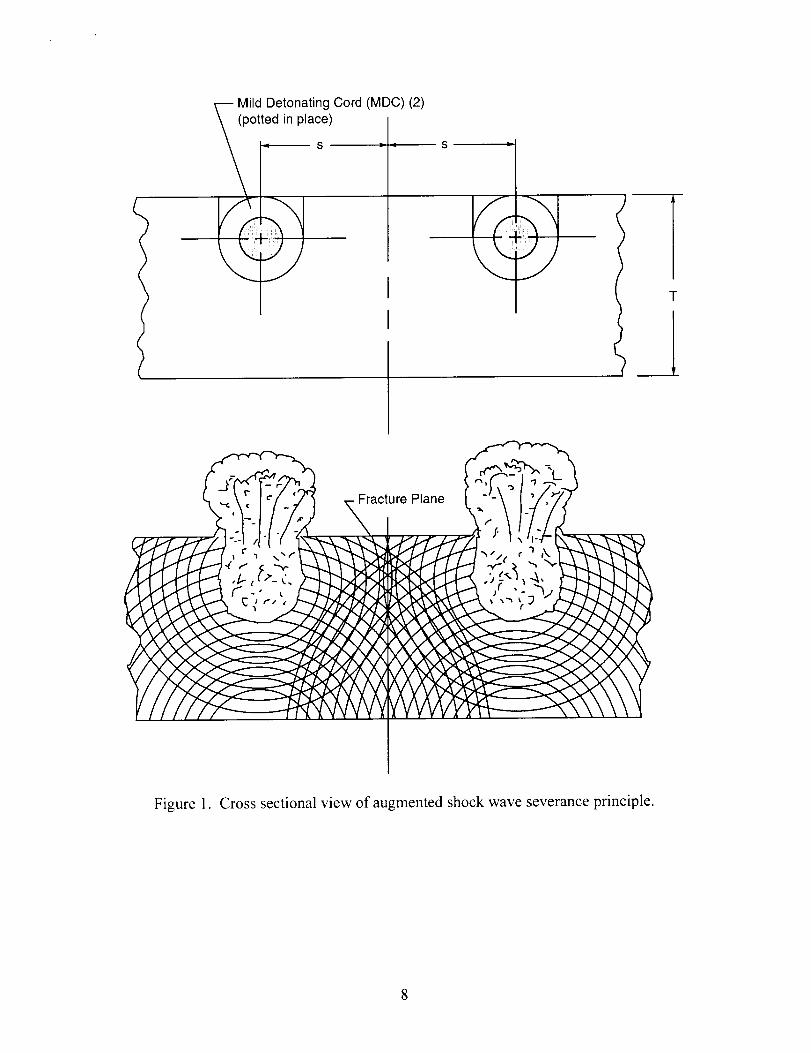
Theresultsof thethird full-scaletest(figures4 and5) left thecanopyessentiallyintact,ashadbeenobservedin thefirst two tests.Little deflectionwasobservedin thehigh-speedvideo. Theintersectionshadbeenpunchedout,andtheaft transversepathwastotally severed,asobservedin theprevioustest. A major,totally severedcrackoccurreddiagonallyacrosstheright-handpanel,figure5. This piecewaseasilypulledout by hand,figure 6, asweretheremainingportions,asshownin figure 7. Completeseveranceoccurredoneveryfractureline.
CONCLUSIONS
Thispaperdescribesa successfuldevelopmentof aunique3-parallel-cord,augmentedshockwaveapproachto explosivelyfractureatough,polycarbonateF-16aircraft canopyto allowthrough-canopycrewegress.A varietyof lessonswerelearnedin materialevaluations,small-scaleandmini-paneltests,andfull-scalesystemtests.
Polycarbonatehasa thermalmemorythatmustberecognizedandcontrolled. To maintainhighstrengthandfractureresistanceof military gradematerial,thermalelevationsto significantsofteningpoint levelsmustbeminimized. That is,to assurerepeatableexplosivefractureproperties,processesto createcanopiesinto final shapemustbeconsistent.
Small-scaleandmini-paneltestsrevealedthat it's a longway from testingsmall piecesto a full-scaletest. Testson full-scalecanopies,whicharemuchstifferandwhichrequiregreaterdistancesof theexplosivepatternsto theedgeof thecanopy,exhibitedmuchhigherresistancetofracture. Specialpatterns(notpresentedhere,dueto ITAR regulations)hadto bedevelopedtobothmaintainexplosivepropagationandpunchout the intersectionsof fracturepaths.
All objectivesof theeffort weremet. Theexplosivematerialscanbe installedon theexteriorofthecanopywithin themold line. The3-cordexplosivepatternis lessvisually obstructivethanthepatternemployedby theHarrier. Installingtheexplosiveon theexterioreliminatesinboardexplosivedebrisor explosivepressure.Thefracturedcanopymaterialbeneathexplosiveintersectionscanbemanagedby positioningtheintersectionsoutsidethecrewenvelope,or bystructuralcontainment.Explosivefractureiscompletein lessthan10milliseconds;theexplosivematerialshavedetonatedcompletelyin lessthan1millisecond. Thecanopymaintainsits shapeafterfunctioning,thuspreventingmajorpiecesfrom enteringthecockpit. Theresidualstrengthof thefracturedcanopyis small;the seatcaneasilythrustasidetheseveredpiecesof thecanopyduringegress.
Theincorporationof this technologyinto futurecrew-escapeapplicationsoffersa varietyofimprovementsovercanopyjettisonsystems.Heavier,strongercanopiescanbeused.Reducingdelaytimesfor canopyjettisoncanexpandcrewescapeenvelopes.Systemreliability canbeincreased;this isa passivesystemthathasnomechanicalinterfacesthat canimproperlyfunction,andfewerinitiation inputs(2 for redundancy)arerequired. Canopyjettison systemsrequireoneor two latches,eachwith a releasedevice,andtwo thrustersor rockets,totaling6to
8 inputs. Canopyfractureshouldweighandcostless. It shouldhavelower maintenancecosts.It will bea single,one-timeinstallationof explosivematerial,which will last the lifetime of thecanopy
REFERENCES
1. Bement,LaurenceJ., Schroeder, James D.; and Schimmel, Morry L.: Explosive Fracturing of
Aircraft Canopy Materials. Presented at the 1992 SAFE Symposium, November 1992, Las
Vegas, Nevada.
2. Bement, Laurence J. and Schimmel, Morry L.: Augmented Shock Wave Severance of
Materials. Presented at the 31 st AIAA/ASME/SAE/ASEE Joint Propulsion Conference, San
Diego, California, July 10-12, 1995.
3. Schimmel, Morry L., Bement, Laurence J., DuBrucq, Glenn F. and Klein, Edward A.:
Fracture/Severance of Materials. Patent 5,780,763, July 14, 1998.
- Mild Detonating Cord (MDC) (2)
(potted in place)S _"
I
S
?
-VT
_1
Plane
Figure 1. Cross sectional view of augmented shock wave severance principle.

Figure 2. Concept for explosive fracture of F-16 aircraft canopy to allow through-canopy crew
egress.
9

Figure3. Testsetupfor third full-scalecanopytest. (Explosiveintersectionshavebeenblankedto accommodateITAR restrictions.)
10
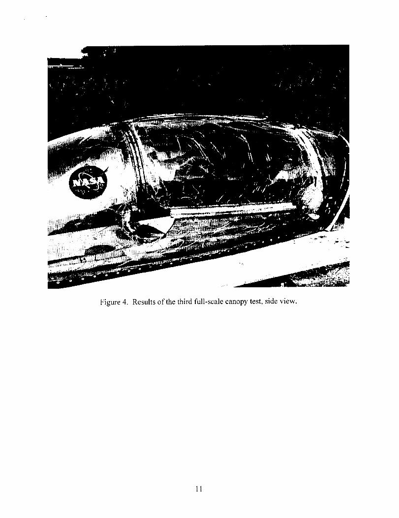
Figure4. Results of the third full-scale canopy test, side view.
11

Figure5. Resultsof thethird full-scalecanopytest,top view.
12

Figure 6. Manually removing the severed panels in the third full-scale canopy test.
13
Figure 7. Final results of the third full-scale canopy test.
14