explosion prevention in coal mine tbm drifts-an ... · explosion prevention in coal mine tbm...
TRANSCRIPT

Explosion Prevention in Coal Mine TBM Drifts-An Operational Knowledge Share
B Belle1 ABSTRACT: Since the first record of a colliery explosion in Belgium, nearly 300 years ago, significant improvements have been achieved in the prevention of explosions in mines. However, based on the past surface TBM project safety statistics, gas explosion hazards are not unique to coal mines but also occur in TBM projects with 48 explosion fatalities recorded worldwide calling for continued diligence and improvements in explosion risk management. Success of TBM in civil engineering infrastructure in poor ground conditions resulted in consideration of its application to a coal mine in QLD. This paper provides a first time case study of TBM application in a coal mine drift development in identifying the explosion hazards and its management. The investigations were extensive with preliminary hazard identification from coal mining approach to application of various ventilation and explosion prevention controls. As in coal mine spontaneous combustion management, explosion hazard was managed by continuous nitrogen injection aimed at maintaining an explosive inert atmosphere in a highly inaccessible TBM pressurized chamber area. The background to hazard identification and control solutions including continuous nitrogen inertisation provided herein would enhance explosion management in both civil and mining TBM applications worldwide.
INTRODUCTION
A Tunnel Boring Machine (TBM) is typically used to develop roadway and utility tunnels with a circular
cross section through a variety of sub surface ground as an alternate to drill and blast excavation methods (Figure 1). The following paragraphs describe TBM operational aspects to those unfamiliar such as in the coal mining industry. For soft subsurface ground conditions, as often encountered in coal mines with up to 7 bar of water pressure, Earth Pressure Balance (EPB) TBMs are used due to their ability to hold up soft ground by maintaining a hydrostatic balance between earth and pressure surrounding the excavation. The TBM (Figure 1) has two main components, i.e., shield which is in direct contact with the excavation face and the back-up system. The shield is essentially a steel skin that separates the interior of the TBM system from the ground. The back-up rolling system carries all the auxiliary elements that the TBM machinery requires for continuous advancement.
The front of the shield accommodates a cutter head that uses a combination of tungsten carbide
cutting bits, and/or hard rock disc cutters (with sizes of 13 to 19 inches) which excavate the face as the cutting head rotates about its central axis. Depending on the ground conditions, additives such as bentonite, polymers and foam are injected from the cutter head to induce ground stability and smoother excavation conditions (Anglo, 2013). Advancement of the TBM face is by the action of thrust cylinders positioned at the rear section of the shield body which press axially against the tunnel liner to push the cutter head forward. The shield is divided into front and rear shield sections connected by hydraulic body frame components that allow for articulation. An erector arm, located at the rear body of the shield is used for installation of the concrete tunnel lining sections. The tunnel muck produced at the TBM’s face is removed by a screw conveyor that feeds onto a transfer conveyor belt that in turn dumps it onto another conveyor for transport to surface.
1 Anglo American Coal, Queensland, Australia/University of Pretoria, South Africa

Figure 1 Overview of coal mine TBM with Explosion R isk Zoning
APPLICATION OF TBM IN COAL MINES
TBMs have been used in mining related projects since the 1950s. Subsurface geological risks typically distinguish these projects from typical civil engineering applications. There have been up to 24 TBM projects in mining worldwide, viz., Canada, Zambia, South Africa, USA, Norway, Germany, Mexico, Chile, Australia, Italy, China, and PNG. Based on the past mining experiences, it was noted by Brox (2013) that every tunnel project and site location is unique in terms of geology, access, terrain/cover, experience of candidate contractors and project completion demands.
During the 1970’s and ‘80’s, Robbins TBMs were used to access coal seams in a number of coal
mines globally, i.e., Selby in the UK, three mines in Germany, the Donkin Morien Mine (under sea access) in Canada and Westcliff mine in NSW (Australia). The West Cliff Colliery Men and Materials Drift had 5 m diameter and was 1595 m long. It was built in 1975/6 with an average advance rate of 27.6 m/week. Documentation of these coal mining TBM applications did not convey any known occurrence of explosion hazards during development. Other known application of TBMs in the mining industry is the 8 km long Los Sulfatos exploration tunnel of 4.5 m diameter developed for Los Bronces mine at an elevation of 4000 m. Key reasons for its selection as a development method were flexibility to access the worksite, natural restrictions related to the portal installations and geotechnical and environmental considerations. The field review showed no known experiences of any methane gas intersections during the 8 km development (Belle, 2010) although a significant inflow of water had to be managed.
Success of TBM technology in establishing surface civil infrastructure and providing alternate means
of rapid access in poor ground conditions, resulted in its consideration of its application at Grosvenor coal mine in QLD to establish the conveyor and men and material transport drift access roadway from the surface. The conveyor drift has a gradient of 1:6 with a length of 762 m and while the transport drift is a 993 m long and has a 1:8 gradient. Considering the geotechnical challenges, the TBM excavation method had to utilize EPB technology which is 135 m long and of 8.0 m diameter (Figure 1). For the first time, a TBM required addressing simultaneously ventilation, gas and cooling management elements, and other related mining hazards. The drift ventilation and gas management systems involved the supply and control of air using an intake and exhaust airway network to manage health and safety risks.
At the time of completing this paper, the TBM had finished the conveyor drift (Figure 6) with a total of
581 rings of 1.4 m length, at a distance of 813 meters from the tunnel opening at the surface. Currently, the TBM is planned to be moved to construct the people and materials drift, involving disassembling the front section of the machine underground. The machine was then retracted out the conveyor drift using
NERZ ERZ1
heavy lift and transport equipment and face ventilation modified to force-exhaust system to manage the Goonyella Middle (GM) seam gas emissions. This conveyor drift was completed over a period of 5 months (Dec 20th to 15th May 2014).
With the ample knowledge on methane gas and its management in coal mines, it is a common practice
in coal mines to continuously monitor and anticipate hazards that could result in explosions. Among various ventilation design factors, this paper will attempt to highlight the identification and management of methane and other gases in TBMs during drift development at Grosvenor from coal miner’s perspective.
COAL MINE TBM EXPLOSION RISK ASSESSMENT
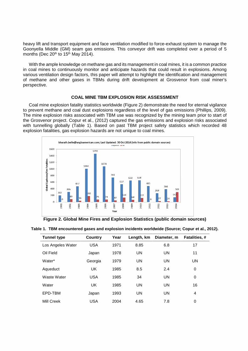
Coal mine explosion fatality statistics worldwide (Figure 2) demonstrate the need for eternal vigilance to prevent methane and coal dust explosions regardless of the level of gas emissions (Phillips, 2009). The mine explosion risks associated with TBM use was recognized by the mining team prior to start of the Grosvenor project. Copur et al., (2012) captured the gas emissions and explosion risks associated with tunnelling globally (Table 1). Based on past TBM project safety statistics which recorded 48 explosion fatalities, gas explosion hazards are not unique to coal mines.
Figure 2. Global Mine Fires and Explosion Statistic s (public domain sources)
Table 1. TBM encountered gases and explosion incid ents worldwide (Source; Copur et al., 2012).
Tunnel type Country Year Length, km Diameter, m Fat alities, #
Los Angeles Water USA 1971 8.85 6.8 17
Oil Field Japan 1978 UN UN 11
Water* Georgia 1979 UN UN UN
Aqueduct UK 1985 8.5 2.4 0
Waste Water USA 1985 34 UN 0
Water UK 1985 UN UN 16
EPD-TBM Japan 1993 UN UN 4
Mill Creek USA 2004 4.65 7.8 0
Electric Cable Hong Kong 2004 UN 4.5 0
Zagros Iran 2009 26 6.73 0
Hard rock Spain 2010 UN UN 0
*Whole team of workers; UN-Unknown
Key lessons from the past civil TBM project experiences (Copur et al., 2002; Brox, 2013) in relation to ignition and explosion management are:
• Adequate knowledge and careful evaluations of technical and non-technical issues such as geology, access, sub-surface cover, fault zones and structures are required.
• Ensuring adequate background information on gas emissions from seams or strata for hydrocarbons.
• Need for skilled and experienced mining engineers. • Use of gas measurement and control systems. The location and calibration of monitors at
strategic locations inside TBM’s cutter head, shield, and segment erector section with automatic TBM shutdown system interlock features is required.
• Ignition prevention techniques such as grouting, pre-drainage, foam injection and sealed lining during the intersection of gassy water inflow conditions should be provided.
Coal Mine TBM Explosion Risk Assessment
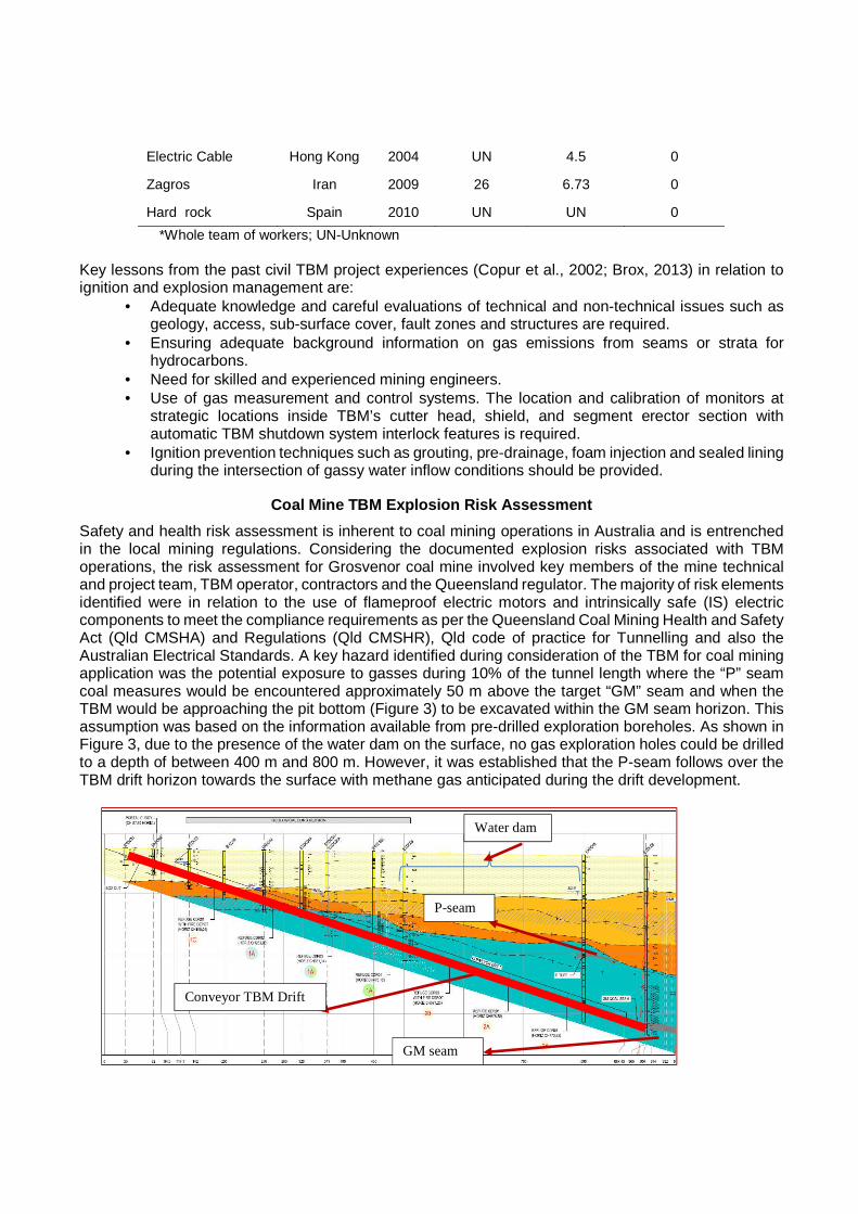
Safety and health risk assessment is inherent to coal mining operations in Australia and is entrenched in the local mining regulations. Considering the documented explosion risks associated with TBM operations, the risk assessment for Grosvenor coal mine involved key members of the mine technical and project team, TBM operator, contractors and the Queensland regulator. The majority of risk elements identified were in relation to the use of flameproof electric motors and intrinsically safe (IS) electric components to meet the compliance requirements as per the Queensland Coal Mining Health and Safety Act (Qld CMSHA) and Regulations (Qld CMSHR), Qld code of practice for Tunnelling and also the Australian Electrical Standards. A key hazard identified during consideration of the TBM for coal mining application was the potential exposure to gasses during 10% of the tunnel length where the “P” seam coal measures would be encountered approximately 50 m above the target “GM” seam and when the TBM would be approaching the pit bottom (Figure 3) to be excavated within the GM seam horizon. This assumption was based on the information available from pre-drilled exploration boreholes. As shown in Figure 3, due to the presence of the water dam on the surface, no gas exploration holes could be drilled to a depth of between 400 m and 800 m. However, it was established that the P-seam follows over the TBM drift horizon towards the surface with methane gas anticipated during the drift development.
Conveyor TBM Drift
P-seam
GM seam
Water dam

Figure 3: Geological long section profile along the conveyor TBM drift. The TBM risk assessment outcome ensured that the TBM incorporated relevant gas monitoring
systems (shield area, cutter chamber, and screw conveyor discharge “stuffing box” assembly area) with automatic shutdown interlock feature should methane detected in any of these TBM sections. In addition, these measures incorporated the NERZ/ERZ requirements as legislated in the QLD Coal Mine Safety and Health Act (CMSHA) and Regulations (CMSHR, 2001).
TBM VENTILATION AND COOLING SYSTEM
Unlike the traditional continuous miner or road header machines in a coal face, the TBM face area at the front of the machine is sealed and potentially could contain a gas mix that may be liberated from the face area in the sealed chamber area. The EPB chamber and screw conveyor section are pressurised during excavation activities. The TBM exhaust ventilation design consisted of 2.0 m diameter steel duct continuously advanced using automated controls behind the TBM. The ducting was connected to a 150 kW surface centrifugal fan. The fan would induce adequate air flow to the face and tunnel. The exhaust ventilation system included a methane sensor to monitor the gas levels as in a typical mine shaft system. The steel duct was connected to a ribbed flexible ducting section to maintain a maximum draw-off distance of 2.0 m from the face during the cutting cycle. The ducting was positioned in such a way that any gas present near the screw conveyor or inbye the TBM area would be removed continuously from the face area. Figure 4 shows the typical ventilation circuit and the pressure-quantity survey results to be in compliance with the Qld CMH and S regulations, S342-S365 (McKew, 2014).
Figure 4: TBM Monthly ventilation survey results (M cKew, 2014).
Figure 5 shows the TBM roadway temperature profile at the rear of the TBM area (behind the gantry 9 of the TBM, i.e., 100 m from the face). One of the observations made from the measured data is that there is a consistent Wet Bulb Temperature (WBT) difference between day and night. It is also noticed that the measured WBT during night shift is higher than the day shift WBT. This implies some type of data inaccuracy and points to the need for other, unbiased continuous real-time velocity and temperature monitors for underground use (Belle, 2014). In addition to TBM heat load, steep geothermal gradient and very high surface ambient air temperatures (24°C WBT and 35°C DBT) in the Bowen Basin (Belle and Biffi, 2013) required the need for supplying cooled air during the TBM development to manage the thermal stress. This was achieved by a mobile surface Bulk Air Cooler (BAC) ducting at the drift entrance with a capacity of 15 to 20 m3/s of cooled air supplied at 10°C (Figure 6).

Figure 5: Use of BAC at surface conveyor drift on t emperature profile in the TBM tunnel.
Figure 6. Completed conveyor drift development at G rosvenor coal mine
TBM METHANE EXPLOSION RISK CONTROLS-OPERATIONAL EXP ERIENCES
In 2001, the Queensland legislation formalised the need for Explosion Risk Zones (ERZ) in underground mines that would allow for greater flexibility and continuous methane monitoring with alarms and relevant electrical power trip interlocks with the equipment. Section 286 requires the Site Senior Executive (SSE) to ensure that a risk assessment is carried out to identify the location and type of each ERZ at the mine. The zoning is risk based considering mining activities, absolute levels of methane in the general body (GB) and including foreseeable events and failure modes. The risk zones may be classified as one of ERZ0, ERZ1 and Negligible Explosion Risk Zone (NERZ). Section 287 of the Qld regulation defines ERZ0 as an underground mine, or any part of it, where the general body concentration of methane is known to be, or as identified by a risk assessment is likely to be, greater than 2%. To avoid any doubt, it is declared that, if the general body concentration of methane in a part of the mine that is defined as ERZ1 or NERZ becomes greater than 2%, then that part becomes an ERZ0.
Section 288(1) of the Queensland regulation defines ERZ1 as an underground mine, or any part of it,
where the general body concentration of methane is known to range, or is shown by a risk assessment as likely to range, from 0.5% to 2%. In addition, Section 288 (2) defines each of the following places is an ERZ1-
(a) a workplace where coal or other material is being mined, other than by brushing in an outbye
Exhaust duct
Air cooling duct
Conveyor

location; (b) a place where the ventilation does not meet the requirements for ventilation mentioned in section
343 or 344; (c) a place where connections, or repairs, to a methane drainage pipeline are being carried out; (d) a place where holes are being drilled underground in the coal seam or adjacent strata for
exploration or seam drainage; (e) a place, in a panel, other than a longwall panel that is being extracted, inbye the panel’s last
completed cut-through; (f) a goaf area; (g) each place on the return air side of a place mentioned in paragraphs (a) to (f), unless the place is
an ERZ0 under section 287; (h) the part of a single entry drive with exhaust ventilation inbye the last fixed ventilation ducting in
the drive.
Section 289(1) of the Queensland regulation defines negligible explosion risk zone (NERZ) as an underground mine, or any part of it, where the general body concentration of methane is known to be, or is identified by a risk assessment as likely to be, less than 0.5%. As in all coal mines, the TBM work area requires explosion risk zoning (ERZ) and is shown below in Figures 1 and 7.
Figure 7: Gas monitoring stations on the TBM face a rea
The principal method of gas control from rib emissions during TBM development is the continued
application of pre-cast concrete linings installed around the excavation’s perimeter within the shield (but behind the bulk-head) as the TBM advances. Another gas control measure was provided by the use of the auxiliary face ventilation described above. The concrete lining is fully grouted as the shield advances, sealing the perimeter of the excavation from gas or water ingress. The section between the bulk-head and cutting face [cutting chamber] typically is an area where gas liberated from the surrounding strata is expected to be present. During EPB controlled development, the TBM machine is operated in “closed” mode where the TBM face area is sealed from the general tunnel environment with steel brushes packed with fibrous grease and pressurised with a combination of foaming agents, drilling muds and water. Closed mode operation is principally designed to control ground pressure acting to collapse the side walls of the excavation but also isolates any resultant gas from the general body. One of the positive attributes of coal mining and welfare of its workers is the constant vigilance in identifying the health and safety hazards through continuous and regular monitoring and inspections. There were a number of operational experiences related to identifying the methane hazard and its

management that were previously not well understood or documented in the TBM applications in civil or mining projects. The gas monitoring system that was implemented while the TBM was cutting the stone strata was complemented with deputy’s hand held multi-gas detectors, a regular bag sample regime and the real-time gas sensors present at the face area and at the screw conveyor duct exit. The Carbon Monoxide (CO) limit at conveyor was set at 10 ppm alarm and 30 ppm power trip. As normally done in coal mines, bag samples collected from the TBM area were analysed using the Gas Chromatograph (GC) at a nearby operating coal mine. The early bag sample results from TBM samples showed that hydrogen was generally present in concentrations around 1,000 ppm, even when CO and ethylene were negligible. Based on coal mining experience, there was no reason for concern initially since the regular presence of hydrogen; CO and ethylene indicate any spontaneous combustion of carbonaceous material in the strata. As part of the routine bag sampling and analyses (11th March 2014), elevated levels of CO, CO2, hydrogen, and ethylene in abnormal proportions were encountered while the TBM was cutting in the stone zone (~ 300 m from the surface). Initially, the measured gas levels were reasoned to result from the presence of a range of greases used to positively pressurize the cutter bearings of the TBM. The bag samples collected at the face area and screw conveyor indicated that CH4 was found in the face area (< 2 %) and very low levels of methane (~0.1%) were detected where face/muck removal by the screw conveyor at the snuffing box. Similarly, the levels measured at the exhaust fan on the surface were ~0.1 % to 0.16% in 25 m3/s of air (i.e., 40 l/s of methane). In order to better understand the phenomena, a bag sample strategy was implemented to collect samples at 3 am and 3 pm each day with results in relation to the TBM advance rate and its location shown in Figures 8 and 9.
Figure 8: Measured methane levels in bag samples fr om the TBM shield area
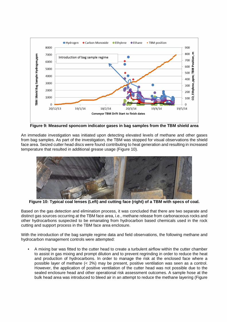
Figure 9: Measured sponcom indicator gases in bag s amples from the TBM shield area
An immediate investigation was initiated upon detecting elevated levels of methane and other gases from bag samples. As part of the investigation, the TBM was stopped for visual observations the shield face area. Seized cutter head discs were found contributing to heat generation and resulting in increased temperature that resulted in additional grease usage (Figure 10).
Figure 10: Typical coal lenses (Left) and cutting f ace (right) of a TBM with specs of coal.
Based on the gas detection and elimination process, it was concluded that there are two separate and distinct gas sources occurring at the TBM face area, i.e., methane release from carbonaceous rocks and other hydrocarbons suspected to be emanating from hydrocarbon based chemicals used in the rock cutting and support process in the TBM face area enclosure. With the introduction of the bag sample regime data and field observations, the following methane and hydrocarbon management controls were attempted:
• A mixing bar was fitted to the cutter head to create a turbulent airflow within the cutter chamber to assist in gas mixing and prompt dilution and to prevent regrinding in order to reduce the heat and production of hydrocarbons. In order to manage the risk at the enclosed face where a possible layer of methane (< 2%) may be present, positive ventilation was seen as a control. However, the application of positive ventilation of the cutter head was not possible due to the sealed enclosure head and other operational risk assessment outcomes. A sample hose at the bulk head area was introduced to bleed air in an attempt to reduce the methane layering (Figure

11). • In order to eliminate the presence of voids inside the TBM’s pressurized cutting chamber, the
quantity of the injected bentonite and foam mixture was increased. This control resulted in increased muck temperature. Alternatively, bentonite use was reduced and foam quantity was increased to reduce the operating temperature (Figure 12). At this stage, it was noted that the cutting strata was a mixture of hard and soft layers interspersed with carbonaceous pockets.
• Considering the presence of other hydrocarbons, the thrust pressure and cutting rate were reduced to minimize the muck operating temperature in conjunction with the introduction of a muck heat Trigger Action Response Plan (TARP) with additional foam/fluid mix. Reduced thrust pressure of the EPB-TBM and implementation of muck heat TARP to 45 °C further reduced the generation of hydrocarbon products.
• Lastly, as used in coal mine spontaneous combustion management and goaf seal management, continuous low temperature enabled Floxal nitrogen to be introduced, instead of compressed air for the generation of foam designed to minimise void creation. This resulted in the generation of an inert atmosphere in the face area and reduced heat generation that otherwise would have stimulated hydrocarbon generation.
Figure 11: Methane sampling/bleed hose (left) behin d the cutter bulkhead (right).
Figure 12: Influence of muck temperature and nitrog en injection to TBM shield area.
Figures 13 and 14 shows the influence of injecting of nitrogen through the existing in-situ Bentonite line directly into the cutter chamber to create an inert atmosphere. Purging of the cutter chamber was introduced after cutter inspections to ensure an inert atmosphere is provided prior to rotating the cutter head. After the introduction of nitrogen, the methane gas from the carbonaceous material present in the
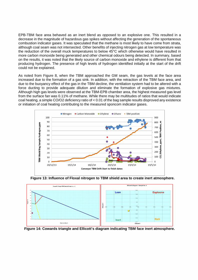
EPB-TBM face area behaved as an inert blend as opposed to an explosive one. This resulted in a decrease in the magnitude of hazardous gas spikes without affecting the generation of the spontaneous combustion indicator gases. It was speculated that the methane is most likely to have come from strata, although coal seam was not intersected. Other benefits of injecting nitrogen gas at low temperature was the reduction of the overall muck temperatures to below 45°C which otherwise would have resulted in more carbon monoxide being generated and other chemical odours being detected. In summary, based on the results, it was noted that the likely source of carbon monoxide and ethylene is different from that producing hydrogen. The presence of high levels of hydrogen identified initially at the start of the drift could not be explained. As noted from Figure 8, when the TBM approached the GM seam, the gas levels at the face area increased due to the formation of a gas sink. In addition, with the retraction of the TBM face area, and due to the buoyancy effect of the gas in the TBM decline, the ventilation system had to be altered with a force ducting to provide adequate dilution and eliminate the formation of explosive gas mixtures. Although high gas levels were observed at the TBM-EPB chamber area, the highest measured gas level from the surface fan was 0.11% of methane. While there may be multitudes of ratios that would indicate coal heating, a simple CO/O2 deficiency ratio of < 0.01 of the bag sample results disproved any existence or initiation of coal heating contributing to the measured sponcom indicator gases.
Figure 13: Influence of Floxal nitrogen to TBM shie ld area to create inert atmosphere.
Figure 14: Cowards triangle and Ellicott’s diagram indicating TBM face inert atmosphere.

LABORATORY INVESTIGATIONS OF TBM FLUIDS FOR METHANE SOURCES
Based on the measured gas levels obtained from the bag samples taken at the TBM face area, it was decided to identify through laboratory means, whether hydrogen, ethylene, carbon monoxide, ethane and methane are liberated from the heating of chemical fluids used in the operation of the EPB-TBM. Furthermore, after the implementation of nitrogen inertisation as part of the explosion risk management process, laboratory testing was carried out to distinguish between oxidation and thermal degradation of products used in the TBM. The five samples submitted for testing were; foam, polymer foam additive, grease, sealed bearing oil and wear indicator oil. Laboratory testing on the five samples was conducted at SIMTARS by heating each of the samples (except foam) incrementally up to at least 250°C in both nitrogen and normal air flow (Brady, 2014). Out of the five samples tested the most likely product contributing to the elevated hydrogen is the foam. Although not as high as those measured in samples collected from the TBM similar concentrations were measured in samples from both nitrogen and air tests up to ~150°C. Most of the other products tested would produce carbon monoxide and ethylene if heated above 200°C accounting for spikes of these components at various times. Figure 15a to 15e show the generated gas level data from chemical products used in TBM shield area along with the spontaneous combustion indicator gases of four Grosvenor coal samples (i.e., carbon monoxide, hydrogen, ethylene, methane and ethane). The results indicate that at the various temperature conditions of the muck in the TBM face area, the measured gas levels in the face area of the TBM are not as the result of spontaneous combustion activity of any carbonaceous strata material.
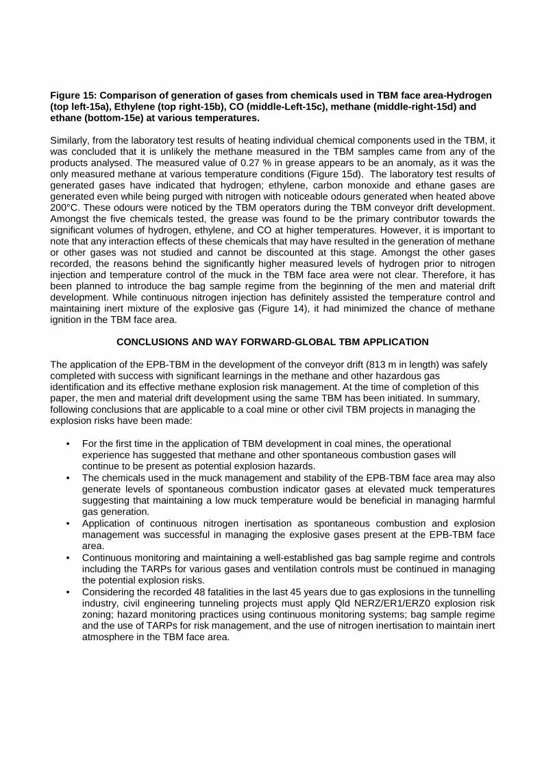
Figure 15: Comparison of generation of gases from c hemicals used in TBM face area-Hydrogen (top left-15a), Ethylene (top right-15b), CO (middl e-Left-15c), methane (middle-right-15d) and ethane (bottom-15e) at various temperatures. Similarly, from the laboratory test results of heating individual chemical components used in the TBM, it was concluded that it is unlikely the methane measured in the TBM samples came from any of the products analysed. The measured value of 0.27 % in grease appears to be an anomaly, as it was the only measured methane at various temperature conditions (Figure 15d). The laboratory test results of generated gases have indicated that hydrogen; ethylene, carbon monoxide and ethane gases are generated even while being purged with nitrogen with noticeable odours generated when heated above 200°C. These odours were noticed by the TBM operators during the TBM conveyor drift development. Amongst the five chemicals tested, the grease was found to be the primary contributor towards the significant volumes of hydrogen, ethylene, and CO at higher temperatures. However, it is important to note that any interaction effects of these chemicals that may have resulted in the generation of methane or other gases was not studied and cannot be discounted at this stage. Amongst the other gases recorded, the reasons behind the significantly higher measured levels of hydrogen prior to nitrogen injection and temperature control of the muck in the TBM face area were not clear. Therefore, it has been planned to introduce the bag sample regime from the beginning of the men and material drift development. While continuous nitrogen injection has definitely assisted the temperature control and maintaining inert mixture of the explosive gas (Figure 14), it had minimized the chance of methane ignition in the TBM face area.
CONCLUSIONS AND WAY FORWARD-GLOBAL TBM APPLICATION
The application of the EPB-TBM in the development of the conveyor drift (813 m in length) was safely completed with success with significant learnings in the methane and other hazardous gas identification and its effective methane explosion risk management. At the time of completion of this paper, the men and material drift development using the same TBM has been initiated. In summary, following conclusions that are applicable to a coal mine or other civil TBM projects in managing the explosion risks have been made:
• For the first time in the application of TBM development in coal mines, the operational experience has suggested that methane and other spontaneous combustion gases will continue to be present as potential explosion hazards.
• The chemicals used in the muck management and stability of the EPB-TBM face area may also generate levels of spontaneous combustion indicator gases at elevated muck temperatures suggesting that maintaining a low muck temperature would be beneficial in managing harmful gas generation.
• Application of continuous nitrogen inertisation as spontaneous combustion and explosion management was successful in managing the explosive gases present at the EPB-TBM face area.
• Continuous monitoring and maintaining a well-established gas bag sample regime and controls including the TARPs for various gases and ventilation controls must be continued in managing the potential explosion risks.
• Considering the recorded 48 fatalities in the last 45 years due to gas explosions in the tunnelling industry, civil engineering tunneling projects must apply Qld NERZ/ER1/ERZ0 explosion risk zoning; hazard monitoring practices using continuous monitoring systems; bag sample regime and the use of TARPs for risk management, and the use of nitrogen inertisation to maintain inert atmosphere in the TBM face area.

• Ensuring relevant operator skills with adequate coal mine ventilation, gas and heat management experience is valuable for the global TBM industry in eliminating explosion risks in the future TBM projects.
ACKNOWLEDGEMENTS
The authors are indebted to various people who have assisted in data collection, application of controls during the conveyor drift TBM application. Author is also grateful to Anglo American for publication of this safety knowledge share and technical reviewers (Australia, South Africa and USA) for their constructive criticisms to improve the quality of this submission.
REFERENCES
Anglo American 2013-Internal TBM Application Document. Belle, B., 2010, Los Bronces Safety Risk Review, Anglo American plc. Belle, B., and Biffi, M., 201, Cooling pathways for deep Australian longwall coal mines of the future, Mine
Ventilation Conference Proceedings, Adelaide, Australia, pp 94-104. Belle, B., 2014, Underground Mine Ventilation Air Methane (VAM) Monitoring – An Australian Journey
towards achieving ‘accuracy’, Proceedings of the Coal Operator’s Conference, Wollongong, Australia.
Brady, D., 2014, Grosvenor TARP Trigger Review Report, Anglo American Internal Document, Australia. Brox, D., 2013, Technical considerations for TBM tunneling for mining projects, Society for Mining,
Metallurgy, and Exploration transactions, USA, Vol. 334, pp 498-505. Copur, H., Cinar, M., Okten, G., and Bilgin, N., 2012, A case study on the methane explosion in the
excavation chamber of an EPB-TBM and lessons learnt including some recent accidents, Tunneling and Underground Space Technology, Tunneling and Underground Space Technology 27 (2012) 159–167.
http://www.legislation.qld.gov.au/LEGISLTN/CURRENT/C/CoalMinSHR01.pdf McKew, 2014, Grosvenor Ventilation Survey report, Anglo American Coal, Australia. Phillips, H., 2009, MVS Symposium, South Africa.