explorer z65dvb-z75dvb prod spec rev 1.0 version 03
DESCRIPTION
Tehnical DVB specifier revisionTRANSCRIPT
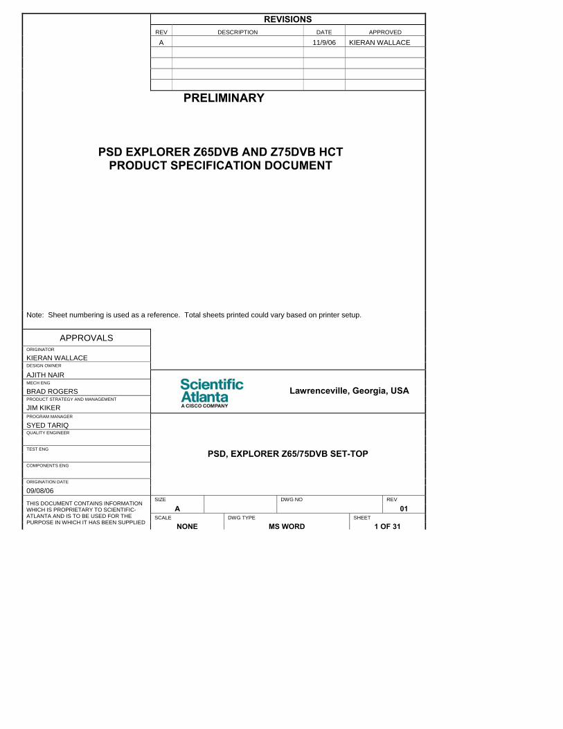
REVISIONS REV DESCRIPTION DATE APPROVED
A 11/9/06 KIERAN WALLACE
PRELIMINARY
PSD EXPLORER Z65DVB AND Z75DVB HCT PRODUCT SPECIFICATION DOCUMENT
Note: Sheet numbering is used as a reference. Total sheets printed could vary based on printer setup.
APPROVALS ORIGINATOR
KIERAN WALLACE DESIGN OWNER
AJITH NAIR MECH ENG
BRAD ROGERS PRODUCT STRATEGY AND MANAGEMENT
JIM KIKER
Lawrenceville, Georgia, USA
PROGRAM MANAGER
SYED TARIQ QUALITY ENGINEER
TEST ENG
COMPONENTS ENG
ORIGINATION DATE
09/08/06
PSD, EXPLORER Z65/75DVB SET-TOP
SIZE DWG NO REV
A 01 SCALE DWG TYPE SHEET
THIS DOCUMENT CONTAINS INFORMATION WHICH IS PROPRIETARY TO SCIENTIFIC-ATLANTA AND IS TO BE USED FOR THE PURPOSE IN WHICH IT HAS BEEN SUPPLIED NONE MS WORD 1 OF 31

Explorer Z65/Z75DVB DHCT
©2006 Cisco Systems, Inc. All rights reserved REV 01 PROPRIETARY INFORMATION SHEET 2 OF 35
<THIS PAGE IS INTENTIONALLY BLANK>
Explorer Z65/Z75DVB DHCT
©2006 Cisco Systems, Inc. All rights reserved REV 01 PROPRIETARY INFORMATION SHEET 3 OF 35
ExplorerTM Digital Set-Top Terminal Model: Z65DVB and Z75DVB Product Specifications Revision 1.0 – Version 03 November 16, 2006 Scientific-Atlanta, Inc., A Cisco Company 5030 Sugarloaf Parkway Lawrenceville, Georgia 30042

Explorer Z65/Z75DVB DHCT
©2006 Cisco Systems, Inc. All rights reserved REV 01 PROPRIETARY INFORMATION SHEET 4 OF 35
Table of Contents 1 INTRODUCTION ............................................................................................................................................................................... 6 2 FEATURES ........................................................................................................................................................................................ 6 2.1 PRODUCT SUMMARY ............................................................................................................................................................... 6
2.2 SOFTWARE SUMMARY ............................................................................................................................................................... 7 2.2.1 SOFTWARE STACK ..................................................................................................................................................................... 8 2.2.2 BOOTLOADER ............................................................................................................................................................................. 8 2.3 SIGNAL PATH OVERVIEW......................................................................................................................................................... 10 2.4 CPU SYSTEM............................................................................................................................................................................ 11 2.5 MEMORY CONFIGURATIONS..................................................................................................................................................... 11 2.6 VIDEO FUNCTIONS ................................................................................................................................................................... 11
2.6.1 Video: MPEG-2 decompression ................................................................................................................................. 11 2.6.2 Video: Output on SCART and UHF connectors ................................................................................................... 12 2.6.3 Video: input on SCART connector ........................................................................................................................... 13 2.6.4 Video: graphics subsystem......................................................................................................................................... 13 2.6.5 Video: Macrovision anti-copy protection (Optional)............................................................................................ 14 2.6.6 Video: Closed Captioning/Teletext............................................................................................................................ 14 2.6.7 Video: Wide Screen Signaling (WSS) ....................................................................................................................... 14 2.6.8 Demultiplexing ................................................................................................................................................................ 14
2.7 AUDIO FUNCTIONS.................................................................................................................................................................... 14 2.7.1 Audio: summary ............................................................................................................................................................. 14 2.7.2 Audio: input and output connectors ........................................................................................................................ 14 2.7.3 Audio: digital decompression .................................................................................................................................... 15 2.7.4 Audio: digital audio decoding .................................................................................................................................... 15 2.7.5 Audio: volume control and mute ............................................................................................................................... 15 2.7.6 Audio: stereo support ................................................................................................................................................... 15 2.7.7 Audio: digital audio decoding (Optional) ................................................................................................................ 15 2.7.8 Audio: multi-audio programming support .............................................................................................................. 15
2.8 CONDITIONAL ACCESS AND SIGNAL SECURITY ....................................................................................................................... 15 2.8.1 Conditional Acces: Nagravision security requirements compliance ............................................................ 16 2.8.2 Conditional Access: smart card expandability (Optional) ................................................................................. 16 2.8.3 Conditional Access: SIM card (Optional) ............................................................................................................... 16
2.9 FRONT PANEL........................................................................................................................................................................... 16 2.9.1 FRONT PANEL: SUMMARY ....................................................................................................................................................... 16
2.9.2 Front panel: keys............................................................................................................................................................ 17 2.9.3 Front Panel: Indicator LED .......................................................................................................................................... 17 2.9.4 Front Panel: infrared (IR) receiver ............................................................................................................................. 17
2.10 REAR PANEL............................................................................................................................................................................. 20 2.10.1 Rear panel: summary ............................................................................................................................................... 20 2.10.2 Rear Panel: DC power inlet..................................................................................................................................... 20 2.10.3 Rear panel: Cable input ........................................................................................................................................... 20 2.10.4 Rear panel: RF output .............................................................................................................................................. 21 2.10.5 Rear panel: TV and VCR SCART outputs ........................................................................................................... 21 2.10.6 Rear panel: stereo audio outputs ......................................................................................................................... 23 2.10.7 Rear panel: smart card reader slot....................................................................................................................... 23 2.10.8 Rear panel: sim card reader slot........................................................................................................................... 23 2.10.9 Rear panel: digital audio output (Optional) ....................................................................................................... 23 2.10.10 Rear panel: 10/100 Base-T Ethernet (Z75 Model Only)................................................................................... 23
3 SET-TOP SPECIFICATIONS ....................................................................................................................................................... 24 3.1 ELECTRICAL SPECIFICATIONS ................................................................................................................................................. 24

Explorer Z65/Z75DVB DHCT
©2006 Cisco Systems, Inc. All rights reserved REV 01 PROPRIETARY INFORMATION SHEET 5 OF 35
3.1.1 Power Supply................................................................................................................................................................... 24 3.1.2 Power Consumption ...................................................................................................................................................... 25 3.1.3 Low Power Standby mode ........................................................................................................................................... 25 3.1.4 CPU system clock speeds ........................................................................................................................................... 25 3.1.5 Frequency plans and tuning resolution................................................................................................................... 25 3.1.6 CABLE input .................................................................................................................................................................... 26 3.1.7 Downstream QAM receiver.......................................................................................................................................... 27 3.1.8 Video Parametric Specifications................................................................................................................................ 27 3.1.9 Audio decoder formats ................................................................................................................................................. 29 3.1.10 Audio output performance...................................................................................................................................... 29 3.1.11 Computer-generated audio..................................................................................................................................... 30
3.2 MECHANICAL SPECIFICATIONS................................................................................................................................................ 30 3.2.1 Dimensions ...................................................................................................................................................................... 30 3.2.2 Chassis color ................................................................................................................................................................... 30 3.2.3 Weight ................................................................................................................................................................................ 31 3.2.4 Tampering/security ........................................................................................................................................................ 31 3.2.5 Adhesive Backed Parts Test and Abrasion Resistance ..................................................................................... 31 3.2.6 Solvent resistance.......................................................................................................................................................... 31
3.3 ENVIRONMENTAL SPECIFICATIONS .......................................................................................................................................... 31 3.3.1 Storage Temperature and Humidity.......................................................................................................................... 31 3.3.2 Operating Temperature and Humidity...................................................................................................................... 31 3.3.3 Heat Rise ........................................................................................................................................................................... 31
3.4 SET-TOP RELIABILITY ............................................................................................................................................................... 31 3.4.1 Field failure rate .............................................................................................................................................................. 31 3.4.2 ESD ..................................................................................................................................................................................... 31 3.4.3 Surge suppression......................................................................................................................................................... 32 3.4.4 Brown-out ......................................................................................................................................................................... 32 3.4.5 Shipping vibration tolerance....................................................................................................................................... 32 3.4.6 Front panel keys ............................................................................................................................................................. 32 3.4.7 Impact test ........................................................................................................................................................................ 32 3.4.8 Handling drop test.......................................................................................................................................................... 32 3.4.9 Microphonic shock ........................................................................................................................................................ 32
3.5 REGULATORY SPECIFICATIONS ............................................................................................................................................... 32 3.6 LABELING .................................................................................................................................................................................. 32 3.7 ROHS DIRECTIVE .................................................................................................................................................................... 34 3.8 WEEE DIRECTIVE.................................................................................................................................................................... 34 3.9 PACKAGING .............................................................................................................................................................................. 34

Explorer Z65/Z75DVB DHCT
©2006 Cisco Systems, Inc. All rights reserved REV 01 PROPRIETARY INFORMATION SHEET 6 OF 35
1 Introduction This Product specification document provides a complete specification of an S-A Broadcast Set-top for a DVB environment. The EXPLORER Z65/Z75DVB Digital Home Communication Terminal (DHCT) supports digital services delivered over a hybrid fiber/coax network. The set-top tuner tunes broadcast digital services only. Analog services are not processed in this terminal, they are bypassed from RF input to the RF output of the set-top w/o processing. UHF modulated output is combined with the RF Bypass when the set-top is in operational ON mode. The Explorer Z75DVB has a 10/100 base T Ethernet output that allows it to be connected to an external modem to allow interactive services such as Video-On-Demand (VOD). The EXPLORER Z65/75DVB DHCT serves varied hardware and software requirements in the PAL markets. The design accommodates the following hardware options:
2 Features
2.1 Product Summary
Table 1 Standard Hardware Features MPEG-2 SP @ ML, MP @ ML, MP @ LL 1 x video downstream 54 to 860 MHz tuner with QAM 64/256 demodulation Power Key Conditional Access 7 software programmable buttons 1 Green Color LED for Power On 1 Green Color LED for Link with external modem (Explorer Z75DVB model only) NEC IR protocol Remote Control DVB descrambler Dual SCART output Analog RF Loop-through combined with Digital signals Audio output L&R on RCA (phono) UHF Modulated Output (Channels 21 to 69) 10/100 Base T Ethernet output (Explorer Z75DVB model only) ISO 7816 smart card reader (slot in housing with electronics optional) Sim card reader (slot in housing with electronics optional) Nagra NASC 1.x compliant
Formatted: Swedish (Sweden)

Explorer Z65/Z75DVB DHCT
©2006 Cisco Systems, Inc. All rights reserved REV 01 PROPRIETARY INFORMATION SHEET 7 OF 35
Table 2 Software Features Enabled by Hardware
Real Time Operating System DVB Subtitle support Software update/download mechanism per bootloader requirements Remote Control specifications per SA transmission protocol specs Teletext re-insertion into VBI Nagra conditional access (Aladin D2D3 CAK) PowerKEY conditional access MPEG-2 PSI and DVB-SI Tables support
2.2 Software Summary The SET-TOP software is programmed in the factory into the set-top Flash memory. The set-top leaves the factory with a code, which at minimum consists of a Bootloader and an application program. The application program will vary for different production batches and at minimum allows for: • Tuning of the “Free-to-Air” i.e. non-scrambled digital programs that exist on a given network, • Set-up screens for the terminal • Basic terminal diagnostics (hidden from the user, available for an authorized technician)
Bootloader Code allows the set-top to be downloaded with the operating software at the time of the installation of the terminal, when the Digital Head-End provides a download spooler with a new software version. Otherwise, the terminal will operate with the software which was programmed in the Flash in the factory. The Bootloader also allows subsequent software upgrades based on the CVT (code version table) mechanism. Optionally, the Bootloader Code can be locked in the first segment of the Flash. Locking of the Bootloader in the factory requires specific authorization from S-A. The application and operating system software in the set-top can be upgraded over the HFC network.
Explorer Z65/Z75DVB DHCT
©2006 Cisco Systems, Inc. All rights reserved REV 01 PROPRIETARY INFORMATION SHEET 8 OF 35
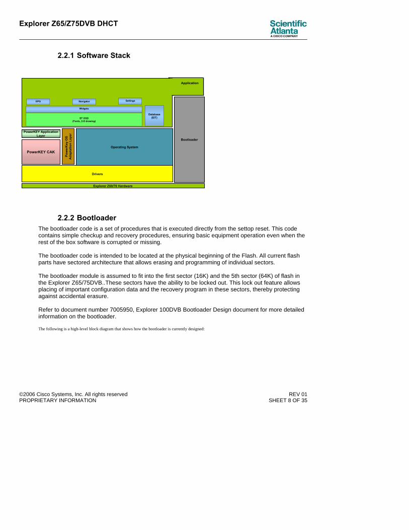
2.2.1 Software Stack
Operating System
Explorer Z60/70 Hardware
Drivers
Bootloader
SettingsNavigatorEPG
Pow
erK
ey O
S A
dapt
atio
n La
yer
ST OSD(Fonts, 2-D drawing)
PowerKEY CAK
PowerKEY Application Layer
Widgets
Database(EIT)
Application
2.2.2 Bootloader The bootloader code is a set of procedures that is executed directly from the settop reset. This code contains simple checkup and recovery procedures, ensuring basic equipment operation even when the rest of the box software is corrupted or missing. The bootloader code is intended to be located at the physical beginning of the Flash. All current flash parts have sectored architecture that allows erasing and programming of individual sectors. The bootloader module is assumed to fit into the first sector (16K) and the 5th sector (64K) of flash in the Explorer Z65/75DVB..These sectors have the ability to be locked out. This lock out feature allows placing of important configuration data and the recovery program in these sectors, thereby protecting against accidental erasure. Refer to document number 7005950, Explorer 100DVB Bootloader Design document for more detailed information on the bootloader. The following is a high-level block diagram that shows how the bootloader is currently designed:

Explorer Z65/Z75DVB DHCT
©2006 Cisco Systems, Inc. All rights reserved REV 01 PROPRIETARY INFORMATION SHEET 9 OF 35
QAM
System Maintenance1
Download Service1
System Reset1
Watch Dog
CVT Monitor
Bootloader Driver
Bootloader(Main)
one sec call
status
download
System Info1
CVT Table
ApplicationBootloader 1 Runtime API service for OS
Application (Main)

Explorer Z65/Z75DVB DHCT
©2006 Cisco Systems, Inc. All rights reserved REV 01 PROPRIETARY INFORMATION SHEET 10 OF 35
2.3 Signal Path Overview The set-top has a single CABLE input driving a single Forward Application Transport (FAT) tuner. The tuner will receive digital video on channels spaced by 8MHz. The tuner can tune in 62.5 KHz steps to accommodate various cable plant alignments.
Figure 1 Explorer Z65/75DVB Block Diagram
LightningProtection
VideoTuner
QAM DEMOD
EBI LMI
VideoEncoder
AudioDACs
IR PortCore
Decryptor PIOs
I2C1
I2C2
ST510x200 MHz 32-Bit RISC CPU
NVM4KB
Flash2MB-4MB 27 MHz
Xtal
Video/CPUSDRAM
16MB-32MB
RFModulatorCH 21-69
10/100Ethernet
MAC/PHY IC
Transformer
PowerKEYSecureuP
CVBS
SIM CardConnector
7 Keys2 LEDs
IR-Rx
RJ-45
EEPROM 512B
IEC 66169-2
IEC 66169-2
RF INPUT
OUTPUTTO TV
Z75DVB only
+12V IN
LEFT
RIGHT
DC-DCCONVERTER
Smart Card
SmartCard
Interface
UART
TV/V
CR
SC
ART
Con
trolle
r
CY
TVS
CAR
TVC
RS
CAR
T
S/PDIF OutS/PDIF Player AC-3 Decoder
Note: Board should be constructed so that the same board can be used for dual SCART OR baseband A/V with S-Video
Explorer Z65/Z75DVB DHCT
©2006 Cisco Systems, Inc. All rights reserved REV 01 PROPRIETARY INFORMATION SHEET 11 OF 35
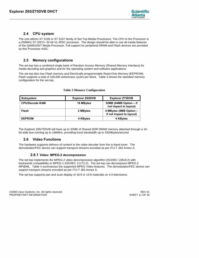
2.4 CPU system The unit utilizes ST 5105 or ST 5107 family of Set-Top Media Processors. The CPU in the Processor is a 200MHz ST-20C2+ 32-bit VL-RISC processor. The design should be able to use all media features of the QAM5105/7 Media Processor. Full support for peripheral SRAM and Flash devices are provided by this Processor ASIC.
2.5 Memory configurations The set-top has a combined single bank of Random Access Memory (Shared Memory Interface) for media decoding and graphics and for the operating system and software applications.
The set-top also has Flash memory and Electrically programmable Read-Only Memory (EEPROM). Flash supports a total of 100,000 write/erase cycles per block. Table 3 shows the standard memory configuration for the set-top.
Table 3 Memory Configuration
Subsystem Explorer Z65DVB Explorer Z75DVB CPU/Decode RAM 16 MBytes 32MB (64MB Option – if
not impact to layout) Flash 2 MBytes 4 MBytes (8MB Option –
if not impact to layout) EEPROM 4 KBytes 4 KBytes
The Explorer Z65/75DVB will have up to 32MB of Shared DDR DRAM memory attached through a 16-bit wide bus running up to 166MHz, providing burst bandwidth up to 332Mbytes/second
2.6 Video Functions The hardware supports delivery of content to the video decoder from the in-band tuner. The demodulator/FEC device can support transport streams encoded as per ITU-T J83 Annex A.
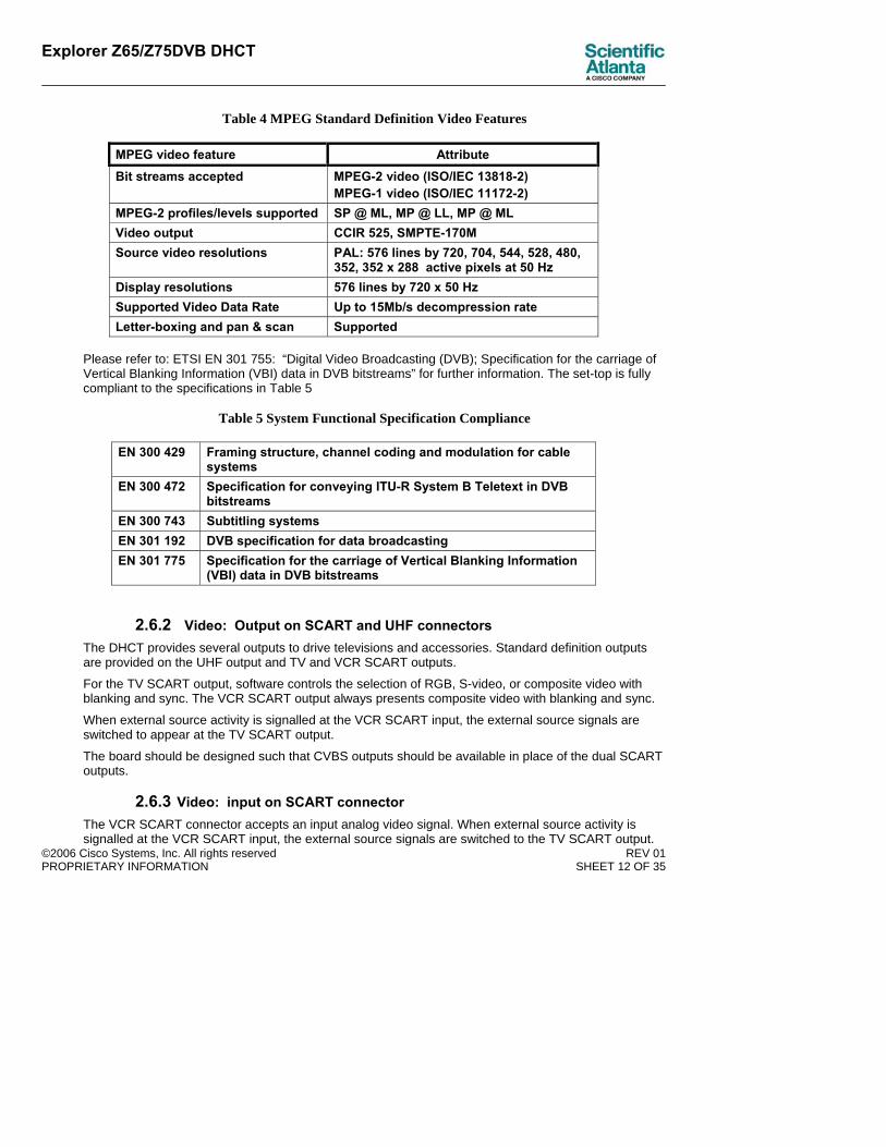
2.6.1 Video: MPEG-2 decompression The set-top implements the MPEG-2 video decompression algorithm (ISO/IEC 13818-2) with backwards compatibility to MPEG-1 (ISO/IEC 11172-2). The set-top can decompress MPEG-2 MP@ML. Table 4 summarizes the supported MPEG Video features. The demodulator/FEC device can support transport streams encoded as per ITU-T J83 Annex A.
The set-top supports pan and scan display of 16:9 or 14:9 materials on 4:3 televisions.
Explorer Z65/Z75DVB DHCT
©2006 Cisco Systems, Inc. All rights reserved REV 01 PROPRIETARY INFORMATION SHEET 12 OF 35
Table 4 MPEG Standard Definition Video Features
MPEG video feature Attribute Bit streams accepted MPEG-2 video (ISO/IEC 13818-2)
MPEG-1 video (ISO/IEC 11172-2) MPEG-2 profiles/levels supported SP @ ML, MP @ LL, MP @ ML Video output CCIR 525, SMPTE-170M Source video resolutions PAL: 576 lines by 720, 704, 544, 528, 480,
352, 352 x 288 active pixels at 50 Hz Display resolutions 576 lines by 720 x 50 Hz Supported Video Data Rate Up to 15Mb/s decompression rate Letter-boxing and pan & scan Supported
Please refer to: ETSI EN 301 755: “Digital Video Broadcasting (DVB); Specification for the carriage of Vertical Blanking Information (VBI) data in DVB bitstreams” for further information. The set-top is fully compliant to the specifications in Table 5
Table 5 System Functional Specification Compliance
EN 300 429 Framing structure, channel coding and modulation for cable systems
EN 300 472 Specification for conveying ITU-R System B Teletext in DVB bitstreams
EN 300 743 Subtitling systems EN 301 192 DVB specification for data broadcasting EN 301 775 Specification for the carriage of Vertical Blanking Information
(VBI) data in DVB bitstreams
2.6.2 Video: Output on SCART and UHF connectors The DHCT provides several outputs to drive televisions and accessories. Standard definition outputs are provided on the UHF output and TV and VCR SCART outputs.
For the TV SCART output, software controls the selection of RGB, S-video, or composite video with blanking and sync. The VCR SCART output always presents composite video with blanking and sync.
When external source activity is signalled at the VCR SCART input, the external source signals are switched to appear at the TV SCART output.
The board should be designed such that CVBS outputs should be available in place of the dual SCART outputs.
2.6.3 Video: input on SCART connector The VCR SCART connector accepts an input analog video signal. When external source activity is signalled at the VCR SCART input, the external source signals are switched to the TV SCART output.
Explorer Z65/Z75DVB DHCT
©2006 Cisco Systems, Inc. All rights reserved REV 01 PROPRIETARY INFORMATION SHEET 13 OF 35
Error! Reference source not found. in section Error! Reference source not found. shows the signals on each SCART connector.
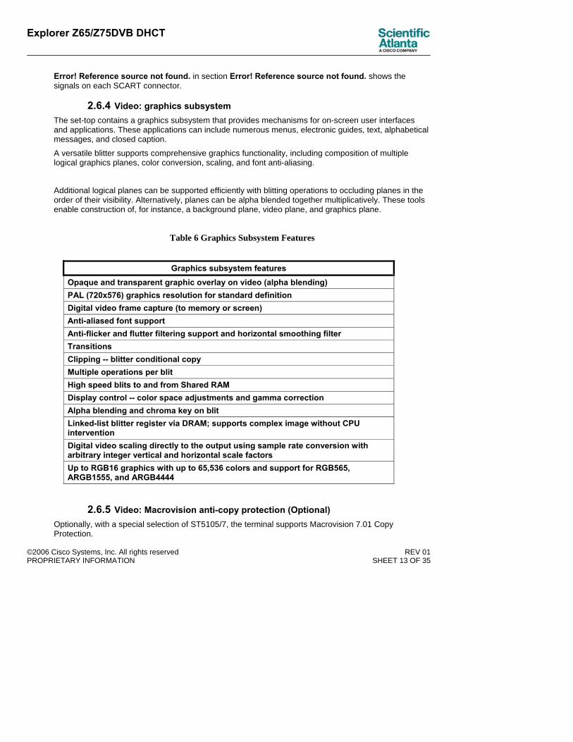
2.6.4 Video: graphics subsystem The set-top contains a graphics subsystem that provides mechanisms for on-screen user interfaces and applications. These applications can include numerous menus, electronic guides, text, alphabetical messages, and closed caption.
A versatile blitter supports comprehensive graphics functionality, including composition of multiple logical graphics planes, color conversion, scaling, and font anti-aliasing.
Additional logical planes can be supported efficiently with blitting operations to occluding planes in the order of their visibility. Alternatively, planes can be alpha blended together multiplicatively. These tools enable construction of, for instance, a background plane, video plane, and graphics plane.
Table 6 Graphics Subsystem Features
Graphics subsystem features Opaque and transparent graphic overlay on video (alpha blending) PAL (720x576) graphics resolution for standard definition Digital video frame capture (to memory or screen) Anti-aliased font support Anti-flicker and flutter filtering support and horizontal smoothing filter Transitions Clipping -- blitter conditional copy Multiple operations per blit High speed blits to and from Shared RAM Display control -- color space adjustments and gamma correction Alpha blending and chroma key on blit Linked-list blitter register via DRAM; supports complex image without CPU intervention Digital video scaling directly to the output using sample rate conversion with arbitrary integer vertical and horizontal scale factors Up to RGB16 graphics with up to 65,536 colors and support for RGB565, ARGB1555, and ARGB4444
2.6.5 Video: Macrovision anti-copy protection (Optional) Optionally, with a special selection of ST5105/7, the terminal supports Macrovision 7.01 Copy Protection.

Explorer Z65/Z75DVB DHCT
©2006 Cisco Systems, Inc. All rights reserved REV 01 PROPRIETARY INFORMATION SHEET 14 OF 35
With the appropriate system support and selection of the ST5105/7, the set-top can generate Macrovision 7.01 encoding for the Baseband and RF outputs. This copy protection feature allows the system operator to restrict unauthorized subscribers from copying premium services and events. The default for this capability is Macrovision Off.
2.6.6 Video: Closed Captioning/Teletext The set-top can retrieve Closed Caption/Teletext material from the MPEG data stream of the selected digital channel. The Closed Caption/Teletext material can be inserted onto the appropriate line/s in both fields of the vertical blanking interval for presentation at the baseband and RF video outputs, as specified by EN 300 472 and EN 300 743.
2.6.7 Video: Wide Screen Signaling (WSS) The set-top shall allow Wide Screen Signalling per EN 300 294 to be placed in the vertical interval per the Digital TV Group's recommendations for aspect ratio signalling in response to Active Format Descriptors.
2.6.8 Demultiplexing There are up to 48 PID filters in the Video Decoding processor
2.7 Audio functions
2.7.1 Audio: summary
Table 7 Audio Program Delivery Format and Output.
Program Delivery Format
LEFT / RIGHT Outputs
RF Output SCART S/PDIF Option
Digital Stereo via MPEG Audio
Stereo Monaural Stereo MPEG Audio or PCM
Digital Monaural via MPEG Audio
Monaural on LEFT and RIGHT
Monaural Monaural MPEG Audio or PCM
2.7.2 Audio: input and output connectors Table 7 summarizes the input/output format options of the Explorer Z65/75DVB. The program output appears at the TV/VCR SCART and RF connector. VCR SCART and UHF outputs are software switchable.
2.7.3 Audio: digital decompression The Set-top decodes digital audio encoded as two-channel MPEG-1 Layers 1 and 2 (ISO/IEC 11172-3).
Explorer Z65/Z75DVB DHCT
©2006 Cisco Systems, Inc. All rights reserved REV 01 PROPRIETARY INFORMATION SHEET 15 OF 35
2.7.4 Audio: digital audio decoding The Set-top has an integrated digital audio decoder. The digital audio decoder also operates with two-channel audio streams encoded per MPEG-1 Layers I, and II and simultaneous MPEG-1 audio decoding.
All MPEG input bit rates supported with sampling Frequencies of Fs = 32KHz , 44.1KHz , and 48 KHz. are supported for MPEG-1. Audio decodes are in single channel, dual channel, stereo, or joint stereo modes.
The set-top should optionally support AC-3 decoding to downmix dolby digital audio signals to the left and right output.
2.7.5 Audio: volume control and mute The set-top supports volume and mute control for the RF and TV SCART outputs. Volume control commands are accepted from the remote control and the front panel keys. The volume step size is 1dB. Mute is controlled from the remote control and the mute attenuation is 60dB minimum.
2.7.6 Audio: stereo support Stereo is supported on the left/right outputs (RCA) and TV/VCR SCART. The RF UHF output modulator always conveys monaural audio.
2.7.7 Audio: digital audio decoding (Optional)
The set-top has an optional digital audio decoder. The decoder operates with Dolby Digital (AC-3) streams with up to 5.1 channels. Multi-channel Dolby Digital programs are downmixed to surround-compatible two-channel signals at the left/right outputs. The original Dolby Digital bitstream is passed to the digital audio output connector for use with external home theater Dolby Digital decoders.
2.7.8 Audio: multi-audio programming support The set-top works with MPEG system features to select among multiple audio streams associated with a single program. For instance, software applications may allow users to select a preferred-language soundtrack when choices are offered in the MPEG transport stream.
• RF-modulated in a UHF carrier on the RF output (IEC –type connector)
• Baseband on an RCA phono connector
2.8 Conditional access and signal security Digital services are protected against eavesdropping and piracy using secret key encryption based on the DVB-CSA algorithm. The control information for the digital descrambler is encrypted, authenticated and protected against tampering using a secure hash algorithm in combination with triple DES.
CAS is used to authorize and descramble the following services:
• Broadcast digital channels
• Event PPV
The cryptographic operations of the CAS are implemented in STi5105/7 Media Processor and in a PowerKey secure microprocessor embedded in the terminal. The set-top is compliant with ETR 289.

Explorer Z65/Z75DVB DHCT
©2006 Cisco Systems, Inc. All rights reserved REV 01 PROPRIETARY INFORMATION SHEET 16 OF 35
Conditional access is implemented in the set-top as a software downloadable module utilizing hardware resources from the set-top as well as a fixed boot loader per the chosen CAK requirements.
2.8.1 Conditional Access: Nagravision security requirements compliance The set-top board should be designed to be compliant to Nagra’s NASC 1.x specifications. The initial customer for the product may be a PowerKEY customer; however, it should be able to be deployed to a Nagra customer without requiring any board changes.
2.8.2 Conditional Access: smart card expandability (Optional) The Explorer Z65/75DVB may optionally have a smart card reader. The smart card reader enables user-insatallabe renewable system security. It also enables expanded/dual conditional access features. The reader is fully compliant with ISO-7816 Part 1 and part 2. The smart card slot allows a minimum of 5,000 insertions without damaging the contacts of the cards or the reader itself. The reader slot location is to be on the back of the unit unless otherwise noted.
2.8.3 Conditional Access: SIM card (Optional) The set-top may use embedded Power-Key CAS for conditional access to decrypt digital services. An optional SIM card reader is provided in the SET-TOP in case of a need for contractual PowerKey upgrades. Insertion of the SIM card can be done easily by hand without need of any tools. When the SIM card is inserted in the SIM card reader the Power-Key secure microprocessor of the SIM card overrides the embedded secure microprocessor for Power key operation.
2.9 Front Panel The front panel shall conform to the following:
Figure 2 at the end of this section shows a front view of the set-tops.
2.9.1 Front Panel: Summary Table 8 Front Panel summary
Standard front panel features
Front Panel Keys 7: Channel Up, Channel Down, Volume Up, Volume Down, Guide, OK, Power
Display None Indicator LEDs 1 Green for Power On and 1
Green for Ethernet Link (Z75 model only)
Infrared Receiver Supports NEC Protocol
2.9.2 Front panel: keys The set-top front panel has a total of 7 keys. The key color is black. All keys have the name of the key etched into the key plastic. The key names are: POWER, GUIDE, OK, VOL-, VOL+, CH-, and CH+.

Explorer Z65/Z75DVB DHCT
©2006 Cisco Systems, Inc. All rights reserved REV 01 PROPRIETARY INFORMATION SHEET 17 OF 35
2.9.3 Front Panel: Indicator LED The Explorer Z65DVB has a single green color indicator LED and lights green when the unit is powered on. The Explorer Z75DVB also contain the power on LED, but also has a second green color indicator LED that lights solid green when there is a link via the Ethernet port with an external modem.
2.9.4 Front Panel: infrared (IR) receiver An infrared (IR) receiver for an NEC protocol remote is mounted behind the front panel. The set-top receives, decodes, and responds under application software control to IR signals.
Table 9 IR Receiver Characteristics
Operating distance from the IR Transmitter:
Straight to STB Remote 30 degrees off center (all directions)
At minimum: 8 meters 6 meters
Table 10 characteristics of S-A remote control
Explorer Z65/Z75DVB DHCT
©2006 Cisco Systems, Inc. All rights reserved REV 01 PROPRIETARY INFORMATION SHEET 18 OF 35
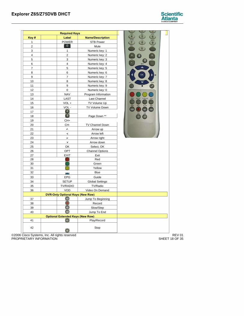
Required Keys Key # Label Name/Description
1 POWER STB Power 2 Mute 3 1 Numeric key: 1 4 2 Numeric key: 2 5 3 Numeric key: 3 6 4 Numeric key: 4 7 5 Numeric key: 5 8 6 Numeric key: 6 9 7 Numeric key: 7 10 8 Numeric key: 8 11 9 Numeric key: 9 12 0 Numeric key: 0 13 NAV Program Information 14 LAST Last Channel 15 VOL + TV Volume Up 16 VOL - TV Volume Down 17
18 Page Down ** 19 CH+ 20 CH- TV Channel Down 21 Arrow up 22 Arrow left 23 Arrow right 24 Arrow down 25 OK Select, OK 26 OPT Channel Options 27 EXIT Exit 28 Red 30 Green 31 Yellow 32 Blue
33 EPG Guide 34 SETUP Global Settings 35 TV/RADIO TV/Radio 36 VOD Video On Demand
DVR-Only Optional Keys (New Row)
37 Jump To Beginning 38 Record 39 Slow/Step 40 Jump To End
Optional Extended Keys (New Row) 41 Play/Record
42
Stop
Explorer Z65/Z75DVB DHCT
©2006 Cisco Systems, Inc. All rights reserved REV 01 PROPRIETARY INFORMATION SHEET 19 OF 35
43 Fast Forward 44 Rewind
** Page Up/Down are new
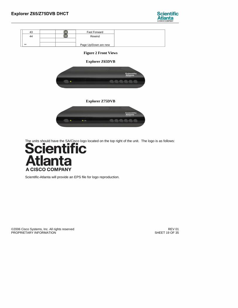
Figure 2 Front Views
Explorer Z65DVB
Explorer Z75DVB
The units should have the SA/Cisco logo located on the top right of the unit. The logo is as follows:
Scientific-Atlanta will provide an EPS file for logo reproduction.

Explorer Z65/Z75DVB DHCT
©2006 Cisco Systems, Inc. All rights reserved REV 01 PROPRIETARY INFORMATION SHEET 20 OF 35
2.10 Rear Panel The rear panel shall conform to the following:
2.10.1 Rear panel: summary Table 11 below shows the rear panel feature summary
Table 11 Rear panel feature summary
Connector Name Connector Type
DC 12V IN Mini Power Jack (2.5mm) CABLE INPUT Female IEC 60169-2 connector TV OUT Male IEC 60169-2 connector TV SCART VCR SCART
AUDIO OUT Color coded left/right audio (white and red) RCA phono jacks
DIGITAL AUDIO OUT Color coded (orange) RCA phono jack (option only)
ETHERNET RJ-45 connector (Z75 model only) (Smart Card Symbol) Smart card reader slot (Sim Card Symbol) Sim card reader slot
Figure 3 Rear View
The back panel shown is for the Explorer Z75DVB model. The Explorer Z65DVB model will be the same with the exception of the Ethernet port. In order to reduce cost, the back panel should have the connector names molded into the plastic. Note: Above drawing needs to show Sim card slot.
2.10.2 Rear Panel: DC power inlet The set-top rear panel uses a Mini Power Jack 2.5mm.
2.10.3 Rear panel: Cable input The set-top has a 75-ohm female IEC 60169-2 connector for the cable input.

Explorer Z65/Z75DVB DHCT
©2006 Cisco Systems, Inc. All rights reserved REV 01 PROPRIETARY INFORMATION SHEET 21 OF 35
2.10.4 Rear panel: RF output The set-top has a male IEC 60169-2 connector for the RF output.
2.10.5 Rear panel: TV and VCR SCART outputs The set-top has two SCART outputs – one for connection to the TV and the other for connection to a VCR. The TV SCART is capable of supporting composite, S-Video or RGB content selectable via software. The board design should be able to accommodate either dual SCART or baseband A/V outputs and s-video without requiring a board re-design.
Table 12 SCART Connector Signals
Pin Description Present on TV SCART
Present on VCR SCART
1 Audio Output Right Output Output 2 Audio Input Right Input Input 3 Audio Output Left Output Output 4 Audio Common Return 5 Blue return 6 Audio Input LEFT Input Input 7 Blue Output Input 8 Function Switching Output Input/Output 9 Green return 10 Intercommunication 2 11 Green Output Input 12 Intercommunication 1 13 Red Return 14 Blanking Return 15 Red Output Input 16 Blanking Output Input 17 Video Output Return 18 Video Input Return 19 CVBS Output Output Output 20 Video Input Input Input 21 Common return
Explorer Z65/Z75DVB DHCT
©2006 Cisco Systems, Inc. All rights reserved REV 01 PROPRIETARY INFORMATION SHEET 22 OF 35
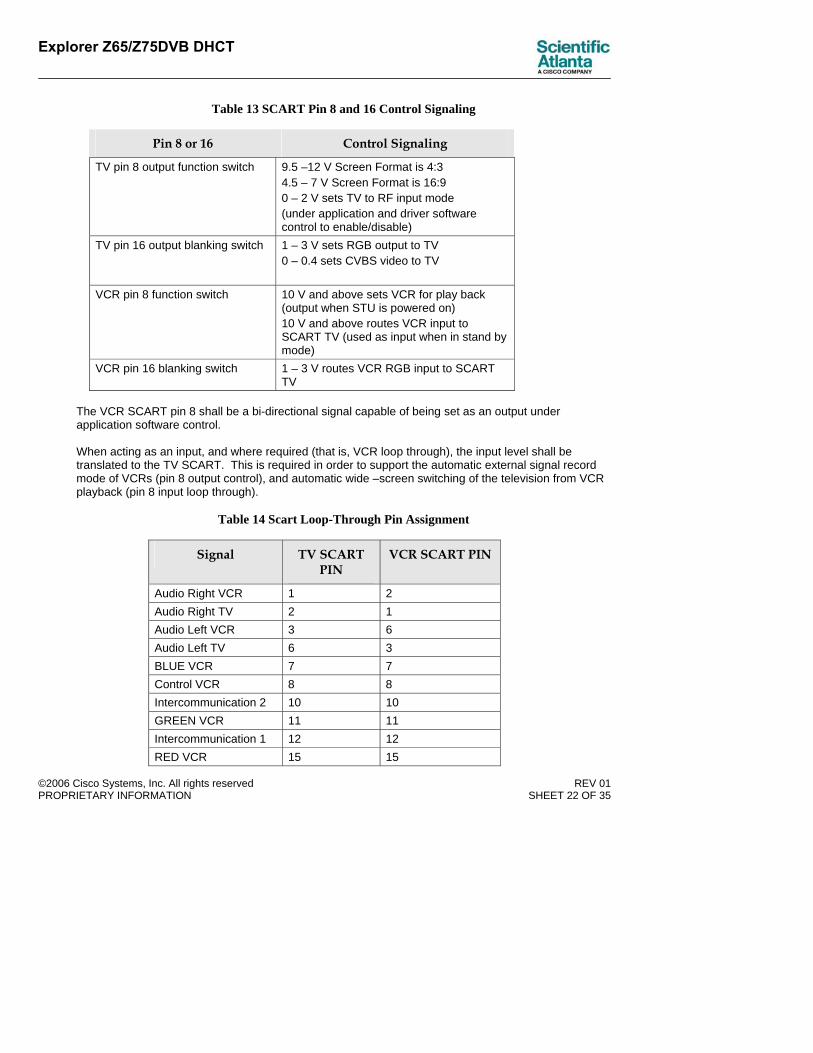
Table 13 SCART Pin 8 and 16 Control Signaling
Pin 8 or 16 Control Signaling
TV pin 8 output function switch 9.5 –12 V Screen Format is 4:3 4.5 – 7 V Screen Format is 16:9 0 – 2 V sets TV to RF input mode (under application and driver software control to enable/disable)
TV pin 16 output blanking switch 1 – 3 V sets RGB output to TV 0 – 0.4 sets CVBS video to TV
VCR pin 8 function switch 10 V and above sets VCR for play back (output when STU is powered on) 10 V and above routes VCR input to SCART TV (used as input when in stand by mode)
VCR pin 16 blanking switch 1 – 3 V routes VCR RGB input to SCART TV
The VCR SCART pin 8 shall be a bi-directional signal capable of being set as an output under application software control. When acting as an input, and where required (that is, VCR loop through), the input level shall be translated to the TV SCART. This is required in order to support the automatic external signal record mode of VCRs (pin 8 output control), and automatic wide –screen switching of the television from VCR playback (pin 8 input loop through).
Table 14 Scart Loop-Through Pin Assignment
Signal TV SCART PIN
VCR SCART PIN
Audio Right VCR 1 2 Audio Right TV 2 1 Audio Left VCR 3 6 Audio Left TV 6 3 BLUE VCR 7 7 Control VCR 8 8 Intercommunication 2 10 10 GREEN VCR 11 11 Intercommunication 1 12 12 RED VCR 15 15

Explorer Z65/Z75DVB DHCT
©2006 Cisco Systems, Inc. All rights reserved REV 01 PROPRIETARY INFORMATION SHEET 23 OF 35
Blanking VCR 16 16 CVBS VCR 19 20 CVBS TV 20 19
2.10.6 Rear panel: stereo audio outputs The set-top has one pair of RCA phono jack providing baseband stereo left/right audio outputs. White insulation is used for the left channel connector and red insulation is used for the right channel connector.
2.10.7 Rear panel: smart card reader slot The set-top has a smart card slot on the rear panel. An optional smart card reader is provided in the set-top in case of a need for a third party conditional access card or for contractual conditional access upgrades. The smart card reader is ISO 7816 compliant.
2.10.8 Rear panel: sim card reader slot The set-top has a sim card slot on the rear panel and may use embedded Power-Key CAS for conditional access to decrypt digital services. An optional SIM card reader is provided in the set-top in case of a need for contractual PowerKey upgrades. Insertion of the SIM card can be done easily by hand without need of any tools. When the SIM card is inserted in the SIM card reader the Power-Key secure microprocessor of the SIM card overrides the embedded secure microprocessor for Power key operation.
2.10.9 Rear panel: digital audio output (Optional) The set-top has an optional RCA phono jack (orange color) providing digital audio output. White insulation is used for the left channel connector and red insulation is used for the right channel connector.
2.10.10 Rear panel: 10/100 Base-T Ethernet (Z75 Model Only) The Explorer Z75DVB set-top has a rear panel IEEE802.3 10/100 base-T port with an RJ-45 connector. The interface supports auto-sense for speed and half/full duplex settings. It allows the set-top to be connected to an external modem out of the Ethernet output.
Table 15 Signals on 10/100BASE-T connector
Pin Signal Pin Signal 1 TD+ (input to set-top) 5 N/C 2 TD- (input to set-top) 6 RD- (output from set-top)3 RD+ (output from set-top) 7 N/C 4 N/C 8 N/C

Explorer Z65/Z75DVB DHCT
©2006 Cisco Systems, Inc. All rights reserved REV 01 PROPRIETARY INFORMATION SHEET 24 OF 35
3 Set-top Specifications
Specifications in this section are limited to basic functional features of the Explorer Z65/75DVB.
Detailed Test Specification document will be prepared by the outside design vendor based on the basic specs below and on a sample of an Explorer SCD (to be provided by S-A). The Test Specification document will be approved by S-A.
The product must meet all the specifications enumerated in the Test Specification document.
3.1 Electrical Specifications
3.1.1 Power Supply The set-top receives power from an external AC to 12V adapter. A switching power supply covers the following input voltage ranges:
• 90 to 270 VAC, 50Hz +/- 5%
Table 16 AC to 12 VDC power adapter
Switching Power Supply Item Min Max
Unit
Input Voltage 90 270 Vac
Input Line Frequency
47 63 Hz
Output Voltage 11.4 12.6 Vdc
Output Current 0 1 A
Ripple And Noise -- 120m Vp-p
Turn-On Delay Time -- 2 Sec
Efficiency 70 -- %
Insulation test 50MΩ at DC500V
--
EMI CISPR22 –EN55022 Class B
Electrostatic Discharge
EN61000-4-2(ESD)
Comment: Need to confirm changes in table are correct

Explorer Z65/Z75DVB DHCT
©2006 Cisco Systems, Inc. All rights reserved REV 01 PROPRIETARY INFORMATION SHEET 25 OF 35
Conducted Susceptiblity
EN61000-4-4 EN61000-4-5
Environment (Operating TMP)
0°C ~ +50°C
Environment (Storage TMP)
-40°C ~ +70°C
3.1.2 Power Consumption Table 17 Power Consumption
3.1.3 Low Power Standby mode The SET-TOP shall be designed in such a way as to consume the least amount of power when the terminal is in the standby mode. This is achieved by turning off the functions that are not needed in the standby mode; however the set-top must still be able to process system messages.
When the terminal is turned on to the Active Mode on pressing the Power/Standby key, the terminal will resume its normal functioning.
3.1.4 CPU system clock speeds
Table 18 Clock Frequencies
CPU internal clock, MHz 200 MHz Shared DDR clock, MHz 166 MHz
3.1.5 Frequency plans and tuning resolution The downstream tuner operates from 54 to 862 MHz (band edge to band edge). Application and driver software controls the specific frequency plan to be tuned. The hardware tuning resolution is 62.5KHz.
Active mode 7W Goal Stand-by mode 6W Goal

Explorer Z65/Z75DVB DHCT
©2006 Cisco Systems, Inc. All rights reserved REV 01 PROPRIETARY INFORMATION SHEET 26 OF 35
3.1.6 CABLE input
Parameter Specification Cable Input connector Female IEC 60169-2 Cable Input impedance 75 Ohm Cable Input return loss 8 dB minimum Cable Input Signal level Range -17dBmV to +20BmV) for 64QAM
(-13dBmV to +20 dBmV) for 256QAM Max Total composite power 34.8 dBmV (95 carriers, each at +15 dBmV)Minimum Signal to Noise Ratio 28dB (QAM64), 34dB (QAM256) Max Level Differential QAM to adjacent analogue : QAM to adjacent QAM :
-10dB peak (QAM64); -6dB peak (QAM256) ±3dB (same type); -6dB (QAM64 next to QAM 256)
C/N QAM 64: TBD 30.5dB typical TBD 25.5dB worst case QAM256: TBD 36.5dB typical TBD 31.5dB worst case
Max slope 15dB, 99 to 859 MHz Noise Figure at maximum range <9.5dB Operational frequency range 54MHz to 862MHz (band edges)
Comment: Need to check this section against BIS specs
Comment: BIS spec is 6 dB

Explorer Z65/Z75DVB DHCT
©2006 Cisco Systems, Inc. All rights reserved REV 01 PROPRIETARY INFORMATION SHEET 27 OF 35
3.1.7 Downstream QAM receiver
Description Specification Frequency range (Application and driver software controls the specific frequency plan to be tuned)
54 to 862 MHz (band edges, 8MHz Channel Spacing)
Modulation formats 64-QAM and 256-QAM per ITU-T J.83 Annex A
Transport format MPEG-2 Systems (ISO/IEC 13818-1)
Private data rate (average, from QAM demod input to CPU DRAM) 3 Mbits/sec
Private data format MPEG-2 (ISO/IEC 13818-1) 64-QAM 41.322 Mbits/sec at
6.887Msym/s maximum Transmission rate, including all overhead 256-QAM 55.096 Mbits/sec at
6.887Msym/s maximum 64-QAM 38.48 Mbits/sec maximum
Transmission rate, information bits 256-QAM 51.31 Mbits/sec maximum
64-QAM, with input C/N in 8 MHz bandwidth of 25.5 dB minimum
-17 dBmV to +13 dBmV
256-QAM, with input C/N in 8 MHz bandwidth of 31.5 dB minimum
-6 dBmV to +17 dBmV
Input level for post-FEC BER less than 10-9
256-QAM, with input C/N in 8 MHz bandwidth of 34.5 dB minimum -13dBmv to -6dBmv
Note: The set-top can also in principle receive 32-QAM and 128-QAM, since modulation formats are compatible with the set-top chip set. Additional QAM drivers are required to detect these QAM modulations. This is not presently required, but may be added in the future versions.
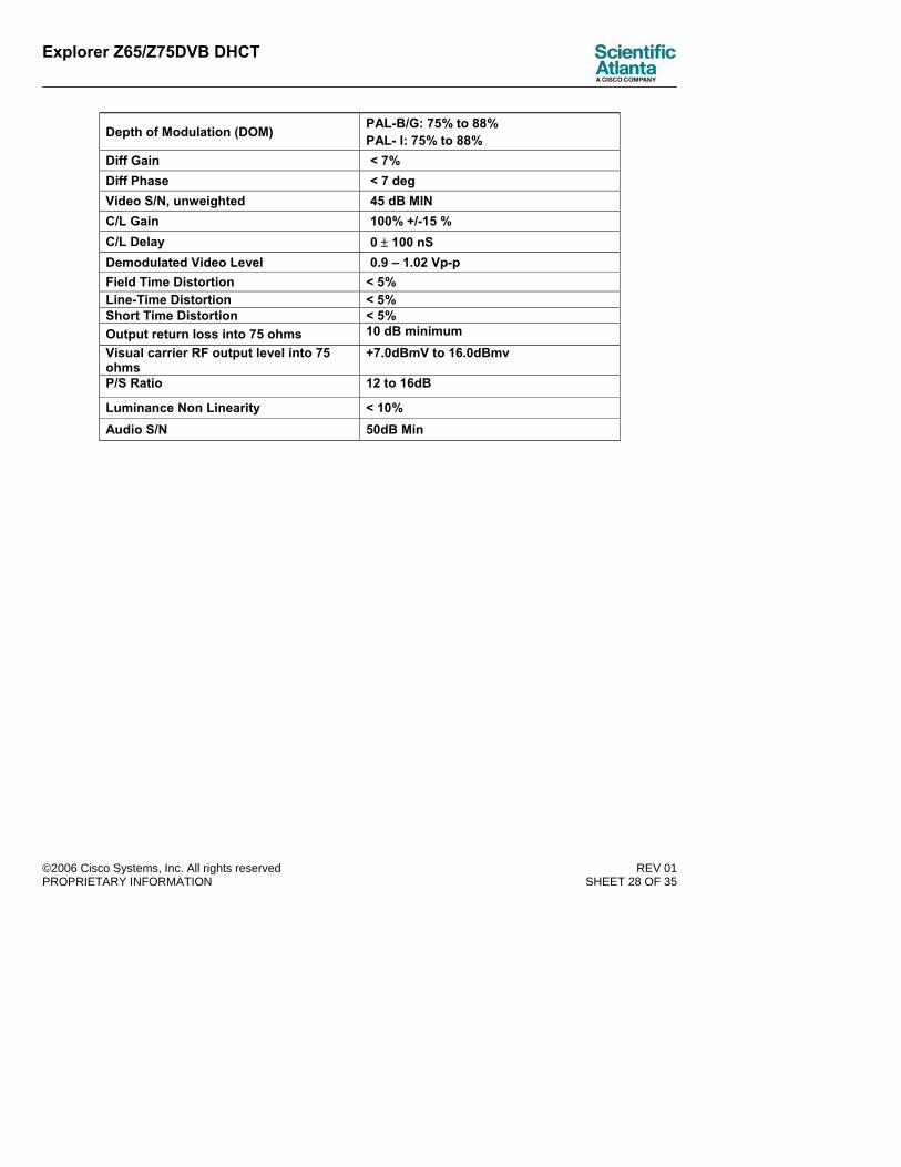
3.1.8 Video Parametric Specifications
RF and TV/VCR SCART Outputs
Description Specification Video Freq Resp 2.5 dB p-p 220KHz – 4.8MHz Output connector Male IEC 60169-2 Output Frequency PAL B/G Channel 21-69
Explorer Z65/Z75DVB DHCT
©2006 Cisco Systems, Inc. All rights reserved REV 01 PROPRIETARY INFORMATION SHEET 28 OF 35
Depth of Modulation (DOM) PAL-B/G: 75% to 88% PAL- I: 75% to 88%
Diff Gain < 7% Diff Phase < 7 deg Video S/N, unweighted 45 dB MIN C/L Gain 100% +/-15 % C/L Delay 0 ± 100 nS Demodulated Video Level 0.9 – 1.02 Vp-p Field Time Distortion < 5% Line-Time Distortion < 5% Short Time Distortion < 5% Output return loss into 75 ohms 10 dB minimum Visual carrier RF output level into 75 ohms
+7.0dBmV to 16.0dBmv
P/S Ratio 12 to 16dB
Luminance Non Linearity < 10% Audio S/N 50dB Min

Explorer Z65/Z75DVB DHCT
©2006 Cisco Systems, Inc. All rights reserved REV 01 PROPRIETARY INFORMATION SHEET 29 OF 35
TV Output Connector – RF Loopthrough RF Bypass is combined with the output of the RF modulator. The RF bypass routes the “Analog Services” from the RF IN ( set-top in stand by mode only) and the “Digital Processed Services” from the internal RF Modulator output ( set-top Powered ON ) “ TO TV” RF output.
Description Specification
Frequency Range 54 MHZ to 862 MHz
Output spurious (limit needed when used with RF Bypass)
-57dBc max.
Gain 0 +/- 2.0dB
3.1.9 Audio decoder formats
Description Specification Type MPEG-1 Standard ISO/IEC 11172-3 MPEG audio layers supported MPEG-1 Layer I and layer II Audio modes Mono, stereo (supporting surround), dual
channel. Sampling rates supported 32 KHz, 44.1 KHz and 48 KHz Data rates supported All MPEG input bit rates supported Key additional features PCM audio mixing with decoded MPEG audio
at MPEG audio sample rate
3.1.10 Audio output performance Audio left/right output
Audio outputs comply with EN 50049-1 specifications
Description Specification Output level into 47 K-ohm load with 1 KHz tone at digital full scale
5.1 V +/- 0.4p-p
Output level into 47 K-ohm load with 1 KHz tone at -11.2 dB FS
0.5 Vrms +/- 0.04 V
Frequency response 20 Hz to 20 KHz Output impedance 1 K-ohm maximum

Explorer Z65/Z75DVB DHCT
©2006 Cisco Systems, Inc. All rights reserved REV 01 PROPRIETARY INFORMATION SHEET 30 OF 35
Amplitude response ripple, 20 Hz to 20 KHz, referenced to response at 1 KHz
+/- 2.0 dBp-p maximum
Crosstalk isolation between channels, 20 Hz to 15 KHz
60 dB minimum
Total harmonic distortion, 1 KHz, measured in 20 Hz to 20 KHz band
0.2 % maximum
Signal-to-noise ratio, referenced to full-scale output, per ITU-R 468-4
72 dB minimum
L/R Channel Balance 0.5 dB L/R Relative Phase < 2% Dynamic Range > 80 dB Volume control 59 steps from 0 dB to -58 dB nominal Volume control step size Approximately 1 dB Hum Supression 60 dB minimum Mute attenuation 60 dB minimum Audio to video transmission time differential (lip sync)
+20 msec (audio leading video) to -40 msec (audio trailing video)
Left output connector Female RCA-phono jack, white insulation Right output connector Female RCA-phono jack, red insulation
3.1.11 Computer-generated audio
Description Specification 8 11.025 22.050 24 Supported sampling rates, KHz
(with software sample rate conversion)
32 44.1 48
3.2 Mechanical Specifications Mechanical specifications shall conform to the following:
3.2.1 Dimensions Dimensions of the Explorer Z65/75DVB are approximately 250 mm (”) wide by 175 mm (”) deep by 49 mm (1.93”) high (including rubber feet).
3.2.2 Chassis color The chassis color is painted black.
Explorer Z65/Z75DVB DHCT
©2006 Cisco Systems, Inc. All rights reserved REV 01 PROPRIETARY INFORMATION SHEET 31 OF 35
3.2.3 Weight The weight of the Explorer Z65/75DVB is approximately 0.3 kg (0.7 lbs.).
3.2.4 Tampering/security Tamper resistant screws are used for the top cover and chassis to inhibit unauthorized access
3.2.5 Adhesive Backed Parts Test and Abrasion Resistance All lithography, graphics and markings on overlays, labels and key plates remains clearly legible after the following test: wipe with ethyl alcohol 30 times; apply Scotch tape and peel off at a 45-degree angle; scratch with fingernail.
3.2.6 Solvent resistance The set-top should be cleaned with a polishing cloth or soft dry cloth. Never clean the unit with furniture polish wax, benzine, insecticides or other volatile liquids since they may damage the finish.
3.3 Environmental specifications Environmental specifications shall conform to the following:
3.3.1 Storage Temperature and Humidity The set-top tolerates storage temperatures from -20 degrees C to +60 degrees C. The set-top can be stored in an environment where the humidity is 5% to 95% non-condensing.
3.3.2 Operating Temperature and Humidity The set-top operates over the ambient still-air temperature range 0 degrees C to 50 degrees C.
The set-top operates in an environment where the humidity is 5% to 95% non-condensing.
3.3.3 Heat Rise The outside touch temperature of the Settop enclosure shall not exceed the ambient by more then 16 degrees C. The internal heat rise should be managed so that all internal parts are operated within their specified derated stress levels.
3.4 Set-top reliability Set-top reliability shall conform to the following:
3.4.1 Field failure rate Unit field failure rates shall be agreed between the parties and shall be designed to ensure minimum customer experience disruption and to ensure minimum operational costs to the customer.
3.4.2 ESD Tested per EN6100-4-2 specifications (Air and Contact).
Comment: BIS spec requires up to 50 degrees C.
Explorer Z65/Z75DVB DHCT
©2006 Cisco Systems, Inc. All rights reserved REV 01 PROPRIETARY INFORMATION SHEET 32 OF 35
3.4.3 Surge suppression The set-top complies with the following regulatory specifications: EN 610004-5, EN 60950, EN 60065.
3.4.4 Brown-out Non-volatile memory does not suffer corruption due to fluctuations in AC line voltage, including slowly decreasing line voltage down to zero volts.
3.4.5 Shipping vibration tolerance The set-top survives, without damage, vibration of 1.25G (5 Hz to 55 Hz) constant acceleration swept from 0 to 60 Hz with a two minute sweep time, and cycled for 60 minutes per each of three axes.
3.4.6 Front panel keys The front panel keys maintain correct operation for at least 100,000 cycles under application force of 450 grams.
3.4.7 Impact test The set-top complies with EN60065.
3.4.8 Handling drop test The set-top shows no visible cracking or separation of the front panel or top cover when dropped onto a hardwood floor from a height of 24 inches on any corner or the front face.
3.4.9 Microphonic shock The set-top remains error free after dropping a remote onto it from a height of five cm.
3.5 Regulatory Specifications The set-top is required to meet the legal regulatory requirements of the country or countries into which it is sold. Identification of standards, compliance testing, product marking, users guide safety content, and obtaining legal certification of compliance is the responsibility of the supplier. It is Scientific-Atlanta’s responsibility to identify the country or countries into which this product will be sold. Scientific-Atlanta reserves the right to review the regulatory requirements the supplier chooses.
• EN 55013
• EN 61000-4-2
• EN 61000-4-3
• EN 61000-4-4
• EN 55022
• EN61000-3-2
• EN61000-3-3
• EN 55020
• EN 60065:2002
• EN 55024
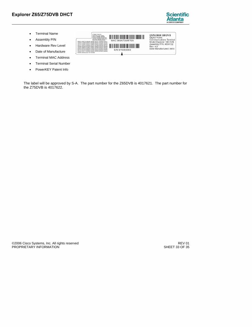
3.6 Labeling Laminated label glued to the terminal provides the following information:
Explorer Z65/Z75DVB DHCT
©2006 Cisco Systems, Inc. All rights reserved REV 01 PROPRIETARY INFORMATION SHEET 33 OF 35
• Terminal Name
• Assembly P/N
• Hardware Rev Level
• Date of Manufacture
• Terminal MAC Address
• Terminal Serial Number
• PowerKEY Patent Info
The label will be approved by S-A. The part number for the Z65DVB is 4017621. The part number for the Z75DVB is 4017622.

Explorer Z65/Z75DVB DHCT
©2006 Cisco Systems, Inc. All rights reserved REV 01 PROPRIETARY INFORMATION SHEET 34 OF 35
3.7 RoHS Directive The set-top hardware will comply in all respects with Directive 2002/ 95/ EC on the Restriction of the Use of Certain Hazardous Substances in Electrical and Electronic Equipment, O.J.(L19)(Jan. 27, 2003)(the “RoHS Directive”) as well as relevant guidance and each individual Member State implementing legislation.
3.8 WEEE Directive The set-top hardware will be appropriately marked and/or identified as required by Directive 2002 / 96 /EC on Waste Electrical and Electronic Equipment Directive (hereafter “WEEE Directive”) and all other legal environmental obligations, laws and regulations.
3.9 Packaging The Explorer Z65/75DVB should come packaged in individual cartons. Each carton should contain the unit’s model number, part number, MAC address, and serial number.
Individual cartons should be packaged together in quantities of six units in a master carton. The master carton should contain two labels: one of the sides showing each of the individually packed units MAC address and serial number and the other side showing the following information:
• Model number
• Part number
• Quantity in carton
• Weight
• Order number
• Serial number range
Master carton and MAC/Serial Number label example

Explorer Z65/Z75DVB DHCT
©2006 Cisco Systems, Inc. All rights reserved REV 01 PROPRIETARY INFORMATION SHEET 35 OF 35
Information label example