explore ct120 site prep
TRANSCRIPT
Technical Publication
Direction 5317456-100Revision 3
GE HEALTHCAREeXplore CT 120 Site Preparation Guide
Copyright 2008 by GE HealthcareAll rights reserved
http://www.gehealthcare.com

This page is intentionally left blank
GE HEALTHCARE
DIRECTION 5317456-100, REVISION 3 EXPLORE CT 120 SITE PREPARATION GUIDE
Page 3
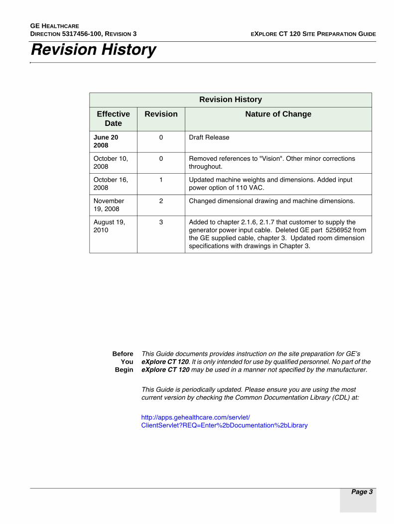
Revision History
Revision History
Effective Date
Revision Nature of Change
June 20 2008
0 Draft Release
October 10, 2008
0 Removed references to "Vision". Other minor corrections throughout.
October 16, 2008
1 Updated machine weights and dimensions. Added input power option of 110 VAC.
November 19, 2008
2 Changed dimensional drawing and machine dimensions.
August 19, 2010
3 Added to chapter 2.1.6, 2.1.7 that customer to supply the generator power input cable. Deleted GE part 5256952 from the GE supplied cable, chapter 3. Updated room dimension specifications with drawings in Chapter 3.
BeforeYou
Begin
This Guide documents provides instruction on the site preparation for GE’s eXplore CT 120. It is only intended for use by qualified personnel. No part of the eXplore CT 120 may be used in a manner not specified by the manufacturer.
This Guide is periodically updated. Please ensure you are using the most current version by checking the Common Documentation Library (CDL) at:
http://apps.gehealthcare.com/servlet/ClientServlet?REQ=Enter%2bDocumentation%2bLibrary

GE HEALTHCARE
DIRECTION 5317456-100, REVISION 3 EXPLORE CT 120 SITE PREPARATION GUIDE
Page 4
This page is intentionally left blank
GE HEALTHCARE DIRECTION 5317456-100, REVISION 3 EXPLORE CT 120 SITE PREPARATION GUIDE
Page 5
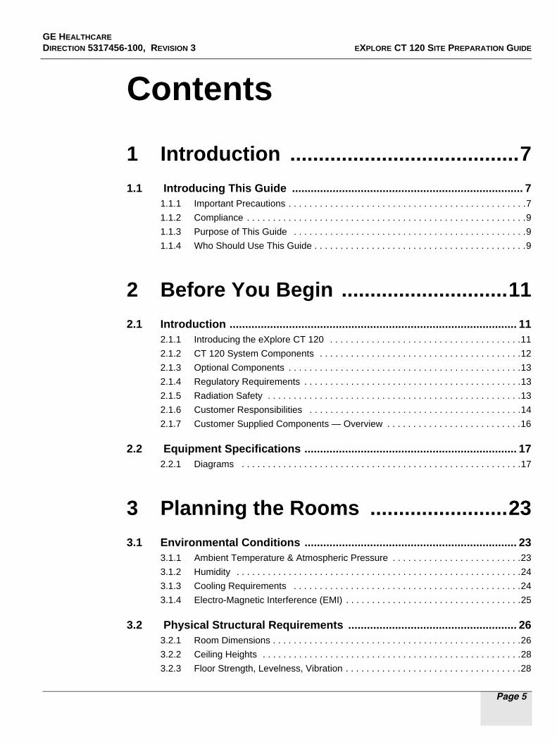
Contents
1 Introduction ........................................7
1.1 Introducing This Guide .......................................................................... 71.1.1 Important Precautions . . . . . . . . . . . . . . . . . . . . . . . . . . . . . . . . . . . . . . . . . . . . . .7
1.1.2 Compliance . . . . . . . . . . . . . . . . . . . . . . . . . . . . . . . . . . . . . . . . . . . . . . . . . . . . . .9
1.1.3 Purpose of This Guide . . . . . . . . . . . . . . . . . . . . . . . . . . . . . . . . . . . . . . . . . . . . .9
1.1.4 Who Should Use This Guide . . . . . . . . . . . . . . . . . . . . . . . . . . . . . . . . . . . . . . . . .9
2 Before You Begin .............................11
2.1 Introduction ............................................................................................ 112.1.1 Introducing the eXplore CT 120 . . . . . . . . . . . . . . . . . . . . . . . . . . . . . . . . . . . . .11
2.1.2 CT 120 System Components . . . . . . . . . . . . . . . . . . . . . . . . . . . . . . . . . . . . . . .12
2.1.3 Optional Components . . . . . . . . . . . . . . . . . . . . . . . . . . . . . . . . . . . . . . . . . . . . .13
2.1.4 Regulatory Requirements . . . . . . . . . . . . . . . . . . . . . . . . . . . . . . . . . . . . . . . . . .13
2.1.5 Radiation Safety . . . . . . . . . . . . . . . . . . . . . . . . . . . . . . . . . . . . . . . . . . . . . . . . .13
2.1.6 Customer Responsibilities . . . . . . . . . . . . . . . . . . . . . . . . . . . . . . . . . . . . . . . . .14
2.1.7 Customer Supplied Components — Overview . . . . . . . . . . . . . . . . . . . . . . . . . .16
2.2 Equipment Specifications .................................................................... 172.2.1 Diagrams . . . . . . . . . . . . . . . . . . . . . . . . . . . . . . . . . . . . . . . . . . . . . . . . . . . . . .17
3 Planning the Rooms ........................23
3.1 Environmental Conditions .................................................................... 233.1.1 Ambient Temperature & Atmospheric Pressure . . . . . . . . . . . . . . . . . . . . . . . . .23
3.1.2 Humidity . . . . . . . . . . . . . . . . . . . . . . . . . . . . . . . . . . . . . . . . . . . . . . . . . . . . . . .24
3.1.3 Cooling Requirements . . . . . . . . . . . . . . . . . . . . . . . . . . . . . . . . . . . . . . . . . . . .24
3.1.4 Electro-Magnetic Interference (EMI) . . . . . . . . . . . . . . . . . . . . . . . . . . . . . . . . . .25
3.2 Physical Structural Requirements ...................................................... 263.2.1 Room Dimensions . . . . . . . . . . . . . . . . . . . . . . . . . . . . . . . . . . . . . . . . . . . . . . . .26
3.2.2 Ceiling Heights . . . . . . . . . . . . . . . . . . . . . . . . . . . . . . . . . . . . . . . . . . . . . . . . . .28
3.2.3 Floor Strength, Levelness, Vibration . . . . . . . . . . . . . . . . . . . . . . . . . . . . . . . . . .28

GE HEALTHCARE
DIRECTION 5317456-100, REVISION 3 EXPLORE CT 120 SITE PREPARATION GUIDE
Page 6
3.2.4 Conduits/Raceways . . . . . . . . . . . . . . . . . . . . . . . . . . . . . . . . . . . . . . . . . . . . . . 29
3.3 Equipment Mounting Requirements (Optional) .................................303.3.1 Floor Mounting, Component Weights & Anchoring . . . . . . . . . . . . . . . . . . . . . . 30
3.3.2 Additional Mounting Considerations . . . . . . . . . . . . . . . . . . . . . . . . . . . . . . . . . 31
3.4 System Input Power Requirements .....................................................323.4.1 Power Requirement Summary . . . . . . . . . . . . . . . . . . . . . . . . . . . . . . . . . . . . . 32
3.4.2 Power Requirement Considerations . . . . . . . . . . . . . . . . . . . . . . . . . . . . . . . . . 32
3.4.3 Facility Source . . . . . . . . . . . . . . . . . . . . . . . . . . . . . . . . . . . . . . . . . . . . . . . . . . 33
3.4.4 Rating . . . . . . . . . . . . . . . . . . . . . . . . . . . . . . . . . . . . . . . . . . . . . . . . . . . . . . . . 33
3.4.5 Regulation . . . . . . . . . . . . . . . . . . . . . . . . . . . . . . . . . . . . . . . . . . . . . . . . . . . . . 33
3.4.6 Grounding . . . . . . . . . . . . . . . . . . . . . . . . . . . . . . . . . . . . . . . . . . . . . . . . . . . . . 33
3.5 Interconnections/Wiring .......................................................................343.5.1 Interconnection Runs . . . . . . . . . . . . . . . . . . . . . . . . . . . . . . . . . . . . . . . . . . . . 34
4 Before Equipment Delivery .............37
4.1 Delivery/Shipping Considerations .......................................................374.1.1 Communicating CT 120 Site Layout to GE . . . . . . . . . . . . . . . . . . . . . . . . . . . . 37
4.1.2 Equipment Handling & Storage . . . . . . . . . . . . . . . . . . . . . . . . . . . . . . . . . . . . . 38
4.1.3 Site Environmental Considerations . . . . . . . . . . . . . . . . . . . . . . . . . . . . . . . . . . 39
4.1.4 Individual Components . . . . . . . . . . . . . . . . . . . . . . . . . . . . . . . . . . . . . . . . . . . 39
4.2 Pre-Install Review .................................................................................414.2.1 Pre-Install Checklists . . . . . . . . . . . . . . . . . . . . . . . . . . . . . . . . . . . . . . . . . . . . . 41

GE HEALTHCARE DIRECTION 5317456-100, REVISION 3 EXPLORE CT 120 SITE PREPARATION GUIDE
Page 7
Chapter 1Introduction
Section 1.1 Introducing This Guide
1.1.1 Important Precautions
DAMAGE IN TRANSPORTATIONAll packages should be closely examined at time of delivery. If damage is apparent write “Damage In Shipment” on ALL copies of the freight or express bill BEFORE delivery is accepted or “signed for” by a GE representative or customer receiving agent. Whether noted or concealed, damage MUST be reported to the carrier immediately upon discovery, or in any event, within 14 days after receipt, and the contents and containers held for inspection by the carrier. A transportation company will not pay a claim for damage if an inspection is not requested within this 14 day period. Call the transportation company immediately after damage is found. At this time be ready to supply name of carrier, delivery date, consignee name, freight or express bill number, item damaged and extent of damage.
CERTIFIED ELECTRICAL CONTRACTOR STATEMENTAll electrical Installations that are preliminary to positioning of the equipment at the site prepared for the equipment shall be performed by licensed electrical contractors. In addition, electrical feeds into the Power Distribution Unit shall be performed by licensed electrical contractors. Other connections between pieces of electrical equipment, calibrations and testing shall be performed by qualified GE Healthcare personnel. The products involved (and the accompanying electrical installations) are highly sophisticated, and special engineering competence is required. In performing all electrical work on these products, GE will use its own specially trained field engineers. All of GE’s electrical work on these products will comply with the requirements of the applicable electrical codes.
The purchaser of GE equipment shall only utilize qualified personnel (i.e., GE’s field engineers, personnel of third-party service companies with equivalent training, or licensed electricians) to perform electrical servicing on the equipment.
IMPORTANT... X-RAY PROTECTIONCAUTION X-ray equipment if not properly used may cause injury. Accordingly, the instructions herein should
be thoroughly read and understood by everyone who will use the equipment before you attempt to place this equipment in operation. General Electric Healthcare will be glad to assist and cooperate in placing this equipment in use.
Although this apparatus incorporates a high degree of protection against x-radiation other than the useful beam, no practical design of equipment can provide complete protection. Nor can any practical design compel the operator to take adequate precautions to prevent the possibility of any persons carelessly exposing themselves or others to radiation.

GE HEALTHCARE
DIRECTION 5317456-100, REVISION 3 EXPLORE CT 120 SITE PREPARATION GUIDE
Page 8
It is important that anyone having anything to do with x-radiation be properly trained and fully acquainted with the recommendations of the National Council on Radiation Protection and Measurements as published in NCRP Reports available from NCRP Publications, 7910 Woodmont Avenue, Room 1016, Bethesda, Maryland 20814, and of the International Commission on Radiation Protection, and take adequate steps to protect against injury.
The equipment is sold with the understanding that the General Electric Company, Medical Systems Group, its agents, and representatives have no responsibility for injury or damage which may result from improper use of the equipment.
Various protective materials and devices are available. It is urged that such materials or devices be used.
Note: See topic 2.1.5 for more information on Radiation Safety.
CONTACTING GE HEALTHCAREToll Free :1-800-526-3593
Email: [email protected]
Website: http://gehealthcare.com/preclinical_imaging
Mail: GE Healthcare
1-1510 Woodcock Street
London, ON, Canada N6H 5S1

GE HEALTHCARE DIRECTION 5317456-100, REVISION 3 EXPLORE CT 120 SITE PREPARATION GUIDE
Page 9
1.1.2 Compliance
GE Healthcare eXplore Series CT scanners are compliant with the United States Radiation Control for Health and Safety Act (Title 21, Code of Federal Regulations, Subchapter J) as they pertain to Cabinet X-Ray Systems (21 CFR 1020.40), FDA Report accession number 0212737-0, and Canadian RED Regulations C.R.C., c. 1370.
This product is also TUV certified for both the U.S. and Canadian markets, to the applicable American and Canadian standards for safety and performance (UL 61010-1:2004 and CAN/CSA C22.2 No. 61010-1:2004).
Certificate #: U8 08 11 68543 001
Report #: 090-809417-000
Date Issued: 2008/11/26
Installation Category II, Pollution Degree 2
1.1.3 Purpose of This Guide
This Guide describes how to prepare a site prior to the delivery of the eXplore CT 120 system. Proper site preparation is the responsibility of the customer and involves adhering strictly to a set of guidelines. Along with an understanding the applicable regulatory requirements for CT imaging (including radiation safety precautions), the customer is expected to plan and build/retrofit the scan, control, and equipment rooms which will house the various components of the eXplore CT 120. Typically site preparation is performed by the customer with input from a GE service representative who will review site plans and conduct an appraisal of the site prior to equipment delivery and installation.
This Guide contains the information the customer needs to prepare the site.
1.1.4 Who Should Use This Guide
This Guide was prepared for customers who have purchased GE Healthcare’s eXplore CT 120.

GE HEALTHCARE
DIRECTION 5317456-100, REVISION 3 EXPLORE CT 120 SITE PREPARATION GUIDE
Page 10
This page is intentionally left blank

GE HEALTHCARE
DIRECTION 5317456-100, REVISION 3 EXPLORE CT 120 SITE PREPARATION GUIDE
Page 11
Chapter 2Before You Begin
Section 2.1Introduction
2.1.1 Introducing the eXplore CT 120
OVERVIEWThe eXplore CT 120 is a pre-clinical x-ray Computed Tomography (CT) scanner for small animals. It is designed specifically for routine and high quality scanning for a number of applications.
The CT 120 utilizes a large FOV and cone beam reconstruction. This provides high throughput, non-invasive, high resolution, isotropic imaging where users may precisely identify the location of an abnormality related to the surrounding anatomical structure.
The system can perform prospectively-gated respiratory and cardiac imaging and has shielded ports for ventilation tubing, anesthetic gases, or monitoring hardware. In addition, the scanner is fully shielded for laboratory use.
KEY SCANNING FEATURES• Acquisition time: typically 1 to 15
minutes for entire volume, depending on scan protocol
• CT data may be acquired with full 360° or half scan
• Pre-configured & user-defined protocol selections
• Live Fluoroscopic viewing for animal positioning
• Large field of view
• Scout view imaging
• Prospective cardiac and respiratory gating

GE HEALTHCARE
DIRECTION 5317456-100, REVISION 3 EXPLORE CT 120 SITE PREPARATION GUIDE
Page 12
ACQUISITION MODESThe system supports the following acquisition modes:
• static planar imaging with or without table motion (acquires a 2 dimensional image from one projection angle)
• dynamic planar imaging (observe the motion of a radioactive tracer through the body through the acquisition of a series of planar images of the specimen over time)
CT PARAMETER CONTROLSGated acquisition is used when the imaging of interest involves a periodic process such as cardiac and/or respiratory motion. The start of each period is defined by an incoming trigger. The CT system supports the gating triggering from:
• ECG triggers
• Respiratory triggers
2.1.2 CT 120 System Components
CT’S ROTATING GANTRYThe CT scanner assembly consists of an x-ray generator and tube, and an x-ray detector with data acquisition electronics. The CT 120’s CT scanner’s x-ray tube has 120 kV maximum tube voltage. It comes with complete system shielding with interlocks suitable for lab use.
X-RAY GENERATORThe 120kV maximum tube voltage system comes with an X-Ray Generator that is positioned beside the CT 120 table. The X-Ray Generator supplies electric power to the X-ray tube; a key function of which is the stepping up and rectification of line voltage to produce a smooth direct current voltage to the X-ray tube.
SPECIMEN TABLE & CRADLEThe computer-controlled, motorized scanning table provides precise specimen positioning features, including live fluoroscopic viewing (2-D image) through the operator console.
The table is designed to support tubing management, animal physiological monitor leads, and animal life supporting systems such as a heated bed. It comes with 2 carbon fiber animal cradles:
- Rat: 75 mm width
- Mouse: 25 mm width.
TABLESIDE CONTROLLERUser controlled table motion (versus automated motion driven by the system) is available via the Tableside Controller. The Tableside Controller is the touch screen panel mounted above the Table. This interface is used to set and position the specimen cradle.

GE HEALTHCARE
DIRECTION 5317456-100, REVISION 3 EXPLORE CT 120 SITE PREPARATION GUIDE
Page 13
OPERATOR CONSOLE All scan acquisition and analysis functions are controlled from the Operator Console. The Operator Console consists of 2 LCD display monitors and a host computer.
2.1.3 Optional Components
PCI ANALYSIS WORKSTATIONA PCI analysis workstation is available for user's applications (separate from the Console) The functionality on the PCI analysis workstation includes the following:
• Registration/fusion display
• Region of interest (ROI)/volume of interest (VOI) analysis
• Segmentation analysis
• Oblique image reformatting
• Volume rendering
• Input/Output (I/O) of DICOM
• Image post-reconstruction filtering such as Gauss.
2.1.4 Regulatory Requirements
Regulatory requirements for imaging facilities vary widely from country to country, and within a country’s various legal districts. As well as conforming to local building and electrical codes, the customer is responsible for ensuring compliance with local regulatory requirements concerning radiation.
2.1.5 Radiation Safety
GE Healthcare’s eXplore scanner is compliant with the United States’ Radiation Control for Health and Safety Act (Title 21, Code of Federal Regulations, Subchapter J) as they pertain to Cabinet X-Ray Systems (21 CFR 1020.40), FDA Report accession number 0212775, and Canadian RED Regulations, C.R.C., c. 1370.
CAUTION X-RAY PROTECTIONX-Ray equipment, if not properly used, may cause injury. It is important that everyone having anything to do with x-radiation be fully acquainted with the recommendations of the National Council on Radiation Protection and Measurements as published in NCRP Reports available from NCRP Publications, 7910 Woodmont Ave., Bethesda, MD 20814, and of the International Commission on Radiation Protection, and take adequate steps to ensure protection against injury.
RADIATION SAFEGUARDSThe GE eXplore CT 120 utilizes a radiation emitting x-ray source and complies with US and Canadian cabinet x-ray standards (as detailed above) which allow the system to be safely operated
GE HEALTHCARE
DIRECTION 5317456-100, REVISION 3 EXPLORE CT 120 SITE PREPARATION GUIDE
Page 14
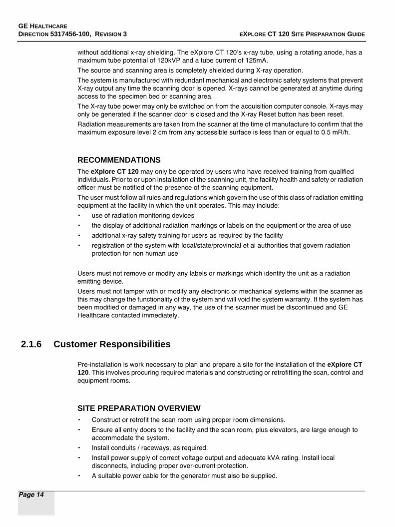
without additional x-ray shielding. The eXplore CT 120’s x-ray tube, using a rotating anode, has a maximum tube potential of 120kVP and a tube current of 125mA.
The source and scanning area is completely shielded during X-ray operation.
The system is manufactured with redundant mechanical and electronic safety systems that prevent X-ray output any time the scanning door is opened. X-rays cannot be generated at anytime during access to the specimen bed or scanning area.
The X-ray tube power may only be switched on from the acquisition computer console. X-rays may only be generated if the scanner door is closed and the X-ray Reset button has been reset.
Radiation measurements are taken from the scanner at the time of manufacture to confirm that the maximum exposure level 2 cm from any accessible surface is less than or equal to 0.5 mR/h.
RECOMMENDATIONSThe eXplore CT 120 may only be operated by users who have received training from qualified individuals. Prior to or upon installation of the scanning unit, the facility health and safety or radiation officer must be notified of the presence of the scanning equipment.
The user must follow all rules and regulations which govern the use of this class of radiation emitting equipment at the facility in which the unit operates. This may include:
• use of radiation monitoring devices
• the display of additional radiation markings or labels on the equipment or the area of use
• additional x-ray safety training for users as required by the facility
• registration of the system with local/state/provincial et al authorities that govern radiation protection for non human use
Users must not remove or modify any labels or markings which identify the unit as a radiation emitting device.
Users must not tamper with or modify any electronic or mechanical systems within the scanner as this may change the functionality of the system and will void the system warranty. If the system has been modified or damaged in any way, the use of the scanner must be discontinued and GE Healthcare contacted immediately.
2.1.6 Customer Responsibilities
Pre-installation is work necessary to plan and prepare a site for the installation of the eXplore CT 120. This involves procuring required materials and constructing or retrofitting the scan, control and equipment rooms.
SITE PREPARATION OVERVIEW• Construct or retrofit the scan room using proper room dimensions.
• Ensure all entry doors to the facility and the scan room, plus elevators, are large enough to accommodate the system.
• Install conduits / raceways, as required.
• Install power supply of correct voltage output and adequate kVA rating. Install local disconnects, including proper over-current protection.
• A suitable power cable for the generator must also be supplied.

GE HEALTHCARE
DIRECTION 5317456-100, REVISION 3 EXPLORE CT 120 SITE PREPARATION GUIDE
Page 15
• All electrical work should be performed by a certified electrician and must conform to local electrical regulations.
• Install an outside telephone line next to the Operator Console (and PCI Analysis Workstation if purchased).
• Install an Ethernet network connection next to the Operator Console (also install a connection next to the PCI Analysis Workstation if part of the system).
• Ensure environmental room conditions meet temperature and humidity requirements.
• Provide a desk for the Operator Console (and PCI Analysis Workstation, if part of the system).
• Arrange for waste disposal of all packaging materials (unless disposal is pre-arranged with GE Healthcare).
• Complete the Pre-installation Check List in Chapter 4.
Note: If seismic considerations are an issue, the customer must inform GE Healthcare.

GE HEALTHCARE
DIRECTION 5317456-100, REVISION 3 EXPLORE CT 120 SITE PREPARATION GUIDE
Page 16
2.1.7 Customer Supplied Components — Overview
The table that follows describes which components are supplied by GE and which are supplied by the Customer (or Contractor).
COMPONENTS SOURCE:
Item Source
Main disconnect control (primary power disconnect)
Customer supplied.For example: GE’s R4502AD, Main Disconnect Control, 480VAC, surface mount with flush mount kit included, two remote push button switches
Table GE supplied
CT Gantry GE supplied
Operator Console GE supplied
System emergency OFF system GE supplied
X-RAY ON warning light(s), controller, and wiring
GE supplied
SYSTEM READY and POWER ON lights, controller and wiring (as required)
GE supplied
Telephone line(s) with outside access (at the Operator Console, PCI Analysis Workstation)
Customer supplied
Ethernet connection, 100 BaseT minimum, Gigabit preferred, with Internet access (at the PCI Analysis Workstation)
Customer supplied
Standard System Interconnect Cables GE supplied
GE phantoms:
1" wire phantom (5248747)
CT value calibration phantom (2382720)
Customer supplied
Operator Console & PCI Analysis Workstation desks
Customer supplied
Generator power input cable
Min. 100A capacity, max. diameter 1.3", min. 3 conductor
Customer supplied
System power input cable GE supplied
Ethernet input cable GE supplied
GE HEALTHCARE
DIRECTION 5317456-100, REVISION 3 EXPLORE CT 120 SITE PREPARATION GUIDE
Page 17
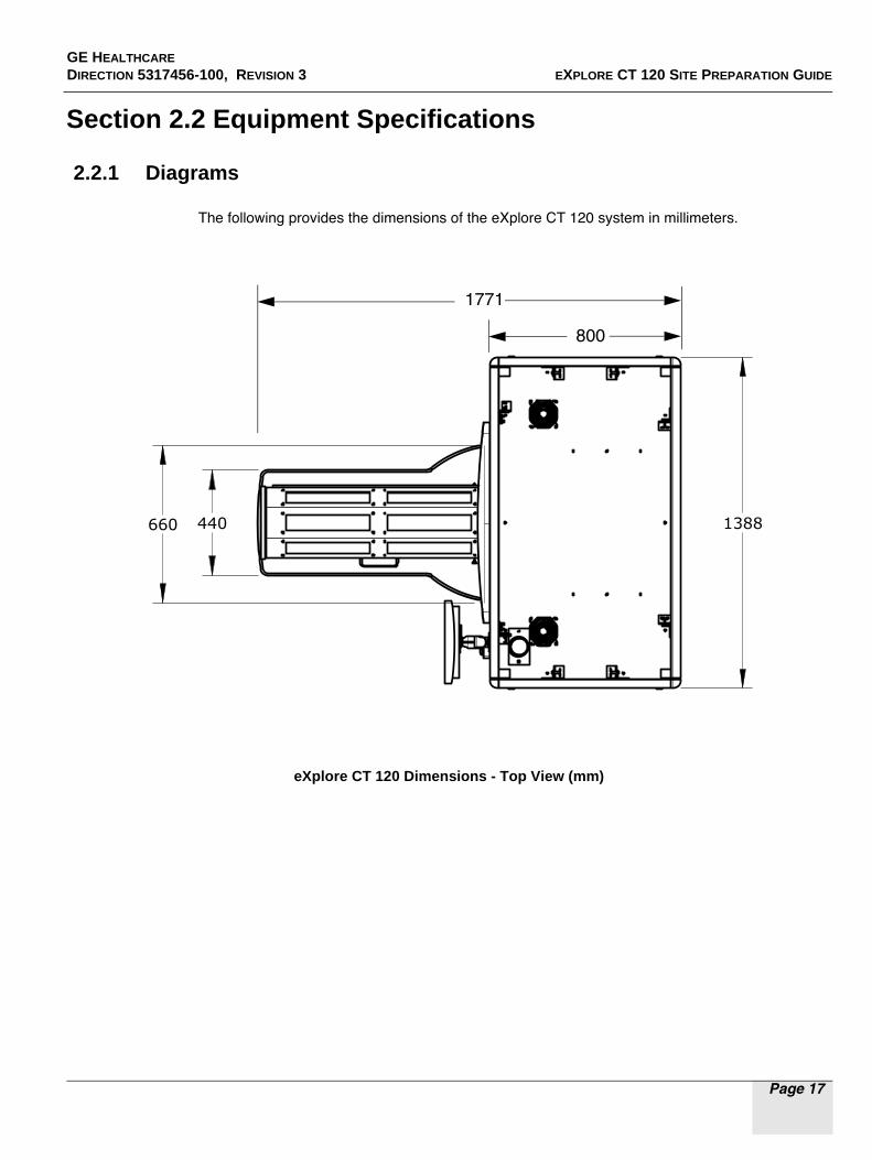
Section 2.2 Equipment Specifications
2.2.1 Diagrams
The following provides the dimensions of the eXplore CT 120 system in millimeters.
eXplore CT 120 Dimensions - Top View (mm)
1388440660
800
1771
GE HEALTHCARE
DIRECTION 5317456-100, REVISION 3 EXPLORE CT 120 SITE PREPARATION GUIDE
Page 18
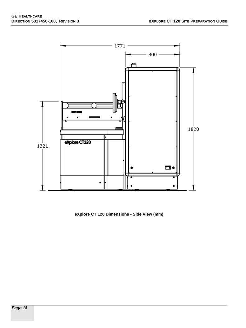
eXplore CT 120 Dimensions - Side View (mm)
800
1771
1321
1820

GE HEALTHCARE
DIRECTION 5317456-100, REVISION 3 EXPLORE CT 120 SITE PREPARATION GUIDE
Page 19
eXplore CT 120 Dimensions - End View (mm)
1388
1892

GE HEALTHCARE
DIRECTION 5317456-100, REVISION 3 EXPLORE CT 120 SITE PREPARATION GUIDE
Page 20
Generator In Inches [mm]
GE HEALTHCARE
DIRECTION 5317456-100, REVISION 3 EXPLORE CT 120 SITE PREPARATION GUIDE
Page 21
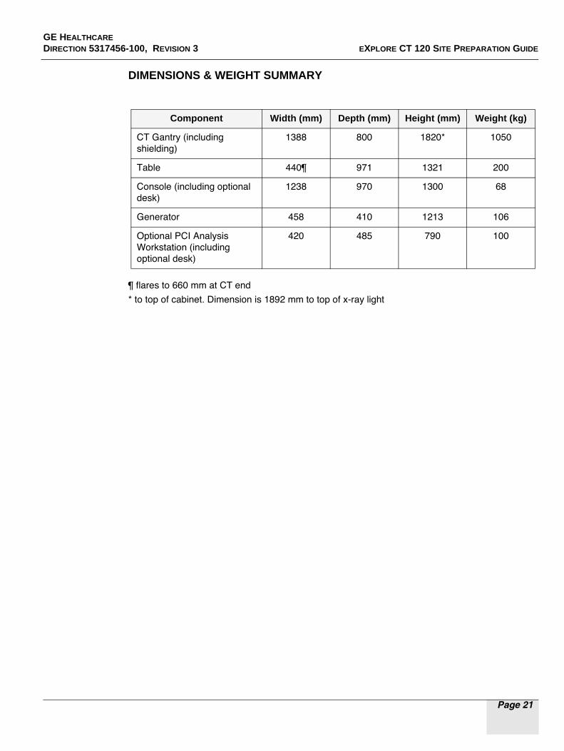
DIMENSIONS & WEIGHT SUMMARY
¶ flares to 660 mm at CT end
* to top of cabinet. Dimension is 1892 mm to top of x-ray light
Component Width (mm) Depth (mm) Height (mm) Weight (kg)
CT Gantry (including shielding)
1388 800 1820* 1050
Table 440¶ 971 1321 200
Console (including optional desk)
1238 970 1300 68
Generator 458 410 1213 106
Optional PCI Analysis Workstation (including optional desk)
420 485 790 100

GE HEALTHCARE
DIRECTION 5317456-100, REVISION 3 EXPLORE CT 120 SITE PREPARATION GUIDE
Page 22
This page is intentionally left blank
GE HEALTHCARE
DIRECTION 5317456-100, REVISION 3 EXPLORE CT 120 SITE PREPARATION GUIDE
Page 23
Chapter 3Planning the Rooms
Section 3.1Environmental Conditions
The eXplore CT 120 may be housed in a single "scan" room.
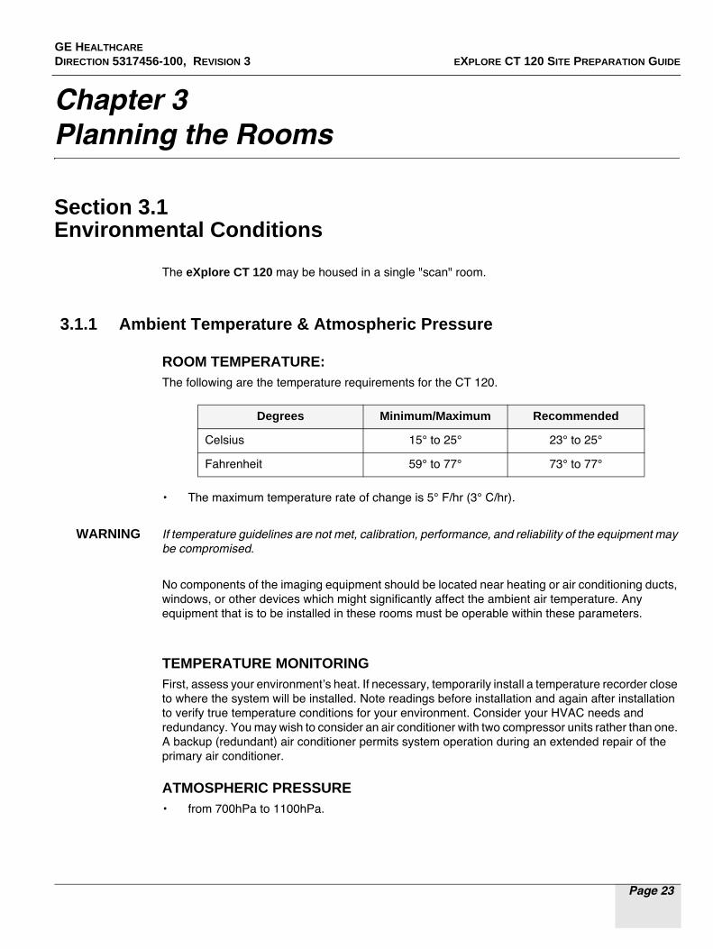
3.1.1 Ambient Temperature & Atmospheric Pressure
ROOM TEMPERATURE: The following are the temperature requirements for the CT 120.
• The maximum temperature rate of change is 5° F/hr (3° C/hr).
WARNING If temperature guidelines are not met, calibration, performance, and reliability of the equipment may be compromised.
No components of the imaging equipment should be located near heating or air conditioning ducts, windows, or other devices which might significantly affect the ambient air temperature. Any equipment that is to be installed in these rooms must be operable within these parameters.
TEMPERATURE MONITORINGFirst, assess your environment’s heat. If necessary, temporarily install a temperature recorder close to where the system will be installed. Note readings before installation and again after installation to verify true temperature conditions for your environment. Consider your HVAC needs and redundancy. You may wish to consider an air conditioner with two compressor units rather than one. A backup (redundant) air conditioner permits system operation during an extended repair of the primary air conditioner.
ATMOSPHERIC PRESSURE• from 700hPa to 1100hPa.
Degrees Minimum/Maximum Recommended
Celsius 15° to 25° 23° to 25°
Fahrenheit 59° to 77° 73° to 77°

GE HEALTHCARE
DIRECTION 5317456-100, REVISION 3 EXPLORE CT 120 SITE PREPARATION GUIDE
Page 24
3.1.2 Humidity
The minimum/maximum relative humidity level should not exceed 30%-60% (non-condensing) in the scan room at all times. The recommended relative humidity level is <50% (non-condensing).
The maximum humidity change in the scan and control room shall not exceed 5% RH/hr. Any equipment that is to be installed in these rooms must operate within these parameters.
HUMIDITY MONITORINGFirst, assess your environment’s humidity. If necessary, temporarily install a humidity recorder close to where the CT 120 will be installed. Note readings before installation and again after installation to verify true humidity conditions for your environment. Consider your HVAC needs and redundancy. You may wish to consider an air conditioner with two compressor units rather than one. A backup (redundant) air conditioner permits CT 120 system operation during an extended repair of the primary air conditioner.
3.1.3 Cooling Requirements
The following cooling requirements do not include cooling for the room lighting, personnel or non-CT 120 equipment present.
Cooling Requirements
Component Watts BTU/hr
Table 520 1,768
Operator’s Console 320 1,088
CT 1,770 6,018
Total: 2,610 8,874

GE HEALTHCARE
DIRECTION 5317456-100, REVISION 3 EXPLORE CT 120 SITE PREPARATION GUIDE
Page 25
3.1.4 Electro-Magnetic Interference (EMI)
This product is a CE compliant device which satisfies requirements regarding Electo-Magnetic Compatibility (EMC), Electro-Magnetic Interference (EMI) pursuant to IEC 60601.
CT 120 SYSTEM LOCATION
Locate the CT 120 system in ambient static magnetic fields of less than 10-4 tesla (1,000 milligauss)
to guarantee specified imaging performance. Ambient AC magnetic fields must be below 10 -6 tesla (10 milligauss) peak.
OPERATOR CONSOLE / COMPUTER EQUIPMENT LOCATION
Locate computer equipment in ambient static magnetic fields of less than 10-3 tesla (10,000 milligauss) to guarantee data integrity.
MAGNETIC MEDIA LOCATION
Locate magnetic media in ambient static magnetic fields of less than 10-3 tesla (10,000 milligauss).
EMI REDUCTIONIf fields of excessive EMI are known or suspected to be present, consult GE service personnel for recommendations. Consider the following if you attempt to reduce EMI:
• External field strength decreases rapidly with distance from source of magnetic field.
• External leakage magnetic field of a three-phase transformer is much less than that of a bank of three single phase transformers of equivalent power rating.
• Large electric motors are a source of substantial EMI.
• High-powered radio signals are a source of EMI.
• Maintain good screening of cables and cabinets.

GE HEALTHCARE
DIRECTION 5317456-100, REVISION 3 EXPLORE CT 120 SITE PREPARATION GUIDE
Page 26
Section 3.2 Physical Structural Requirements
3.2.1 Room Dimensions
The minimum scan room size:
• See Figure 2: Room Dimensions for the CT 120.
COMMON CLEARANCE DIMENSIONS• CT Gantry - back cover removal (rear clearance) 36" (914mm)
• CT Gantry - side cover removal (side clearance) 36" (914mm)
• Area around the main disconnect control 36” (914mm)
• Area between the Table end to obstruction 36” (914mm)

GE
HE
AL
TH
CA
RE
DIR
EC
TIO
N 5
3174
56-10
0 , R
EV
ISIO
N 3
EXP
LO
RE C
T 12
0 S
ITE P
RE
PA
RA
TIO
N G
UID
E
Pag
e 27
Figure 2: Room Dimensions For The CT 120

GE HEALTHCARE
DIRECTION 5317456-100, REVISION 3 EXPLORE CT 120 SITE PREPARATION GUIDE
Page 28
3.2.2 Ceiling Heights
A ceiling height of 108" (2743mm) is recommended. A ceiling height of 79" (2000mm) is the absolute minimum acceptable height for installation purposes.
3.2.3 Floor Strength, Levelness, Vibration
IF MOUNTED TO THE FLOORIt is recommended that the CT 120 be bolted to a concrete floor (although it is not a requirement). This may also be a required if seismic considerations are an issue.
Concrete floors must have a minimum strength of f'c = 2000 psi (1.4 X 10⁷ Pa) at 28 days for mounting floor anchors. It is the responsibility of each customer to have appropriate tests performed to determine and measure concrete strength. Your GE Service representative can assist you.
See the Section Equipment Mounting Requirements for more details.
FLOOR LEVELNESSThe floor levelness requirement is important for accurate patient positioning. Floor levelness in the scan room must not be greater than 0.3125" (8mm) between depression and high spots over any 120" (3048mm) distance within the area of the CT 120 Gantries and the area around the Table.
FLOOR VIBRATIONThe equipment may be sensitive to vibration in the frequency range of 0.5 to 20 Hz depending on the amplitude of the vibration. It is the customers responsibility to contract a vibration consultant or qualified engineer to implement design modifications to meet the specific limits, However, it is ultimately the customer/architect/engineer responsibility to design the site solution.

GE HEALTHCARE
DIRECTION 5317456-100, REVISION 3 EXPLORE CT 120 SITE PREPARATION GUIDE
Page 29
Steady State Vibration
The maximum steady state vibration transmitted through the floor should not exceed 10-3 m/s2 rms maximum single frequency above ambient baseline from 0.5 to 80 Hz (measured during a normal operating period).
Transient Vibration
The behavioral characteristics must be such that any measurable transient disturbance must also
be minimized to less than 0.01 m/s2 peak-to-peak.
Equipment Location
To minimize the interference, the equipment should be placed on a solid floor, located as far as possible from the following vibration sources:
- Parking lots
- Roadways
- Subways
- Trains
- Hallways
- Elevators
- Heliports
- Power plants containing pumps, motors, air handling equipment, and air conditioning units.
3.2.4 Conduits/Raceways
Carefully consider advantages and disadvantages of conduits, floor ducts and surface raceways for running cables. Make cable passageways large enough to install any cable with all other cables already installed.
When routing power cables, all three phase wires and ground must be run in the same conduit or raceway duct-work. Power cables should be routed separately from system control cables (for example, use a separate trough in the duct).
If conduit is used, the minimum conduit size is 4 in. and a maximum of one elbow may be used between pull locations.
Note: See the Sections System Input Power Requirements and Interconnections/Wiring for more detail.

GE HEALTHCARE
DIRECTION 5317456-100, REVISION 3 EXPLORE CT 120 SITE PREPARATION GUIDE
Page 30
Section 3.3 Equipment Mounting Requirements (Optional)
3.3.1 Floor Mounting, Component Weights & Anchoring
It is the customer’s responsibility to provide an approved support structure and mounting method. General Electric is not responsible for any failure of the support structure or method of anchoring.
The following table provides details on floor loadings, component weights, and CT 120 and Table installation and anchoring.
Mounting Requirements
*Use the GE supplied mounting hardware only if approved by qualified personnel.
Component Net Weight
kg
Overall w x d mm
Weight/
Area kg/m2 Load Pattern mm Normal Mounting
Method *
CT 120 1050 1388 x 800 946 1091mm x 465mm Anchor bolts
Table 200 440 x 971 468 742mm x 315mm Anchor bolts
Operator Console
variable 1238 x 970 variable N/A Seismic Kit
Optional PCI Analysis
Workstation
100 420 x 485 491 N/A Seismic Kit
Generator 106 458 x 410 564 N/A Seismic Kit

GE HEALTHCARE
DIRECTION 5317456-100, REVISION 3 EXPLORE CT 120 SITE PREPARATION GUIDE
Page 31
3.3.2 Additional Mounting Considerations
• Anchor the CT Gantry and Table to the floor by a means that will maintain their relative alignment and meet applicable building and other local codes, including seismic structural mounting requirements.
• Floor structure must be capable of withstanding the occupied weight of Table and CT 120, and the individual contact area loading of these components. The Table and CT 120 requires a floor support in the 100 lbs./sq. ft. (490 Kg/sq. m) class or above. Any installation on a floor
with a rating less than 100 lbs./sq. ft. (490 Kg/m2) should be braced to bring it up to this requirement. Localized bracing to support the concentrated loads at the floor contact sections should also be provided.
• Support areas of the Table and CT 120 must rest on solid concrete or other basic flooring, not resilient tile or carpeting which will slowly yield over a period of time and disturb alignment of Table to CT 120.
• Take into consideration all other moving weights such as gurneys or personal equipment.
• No part of floor surface with in the Scan room should be higher than the support area for Table and CT 120.
• A qualified person must verify that the site and method of anchoring are adequate to support loads and maintain Table-to-Gantry alignment. Location of supporting beams, columns, and concrete reinforcing may dictate position of Table-to-Gantry assembly. Use of flush floor duct or conduit in the floor may significantly affect floor strength.
• The method and placement of anchoring through bolts must not reduce structural strength of floor.
• There should not be any piping, gas lines, or electrical conduits embedded into the concrete floor within the footprint of the CT 120 system.
GE HEALTHCARE
DIRECTION 5317456-100, REVISION 3 EXPLORE CT 120 SITE PREPARATION GUIDE
Page 32
Section 3.4 System Input Power Requirements
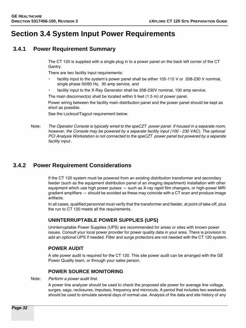
3.4.1 Power Requirement Summary
The CT 120 is supplied with a single plug in to a power panel on the back left corner of the CT Gantry.
There are two facility input requirements:
• facility input to the system’s power panel shall be either 105-115 V or 208-230 V nominal, single phase 50/60 Hz, 30 amp service, and
• facility input to the X-Ray Generator shall be 208-230V nominal, 100 amp service.
The main disconnect(s) shall be located within 5 feet (1.5 m) of power panel.
Power wiring between the facility main distribution panel and the power panel should be kept as short as possible.
See the Lockout/Tagout requirement below.
Note: The Operator Console is typically wired to the speCZT power panel. If housed in a separate room, however, the Console may be powered by a separate facility input (100 - 230 VAC). The optional PCI Analysis Workstation is not connected to the speCZT power panel but powered by a separate facility input..
3.4.2 Power Requirement Considerations
If the CT 120 system must be powered from an existing distribution transformer and secondary feeder (such as the equipment distribution panel of an imaging department) installation with other equipment which use high power pulses — such as X-ray rapid film changers, or high-power MRI gradient amplifiers — should be avoided as these may coincide with a CT scan and produce image artifacts.
In all cases, qualified personnel must verify that the transformer and feeder, at point of take-off, plus the run to CT 120 meets all the requirements.
UNINTERRUPTABLE POWER SUPPLIES (UPS)Uninterruptable Power Supplies (UPS) are recommended for areas or sites with known power issues. Consult your local power provider for power quality data in your area. There is provision to add an optional UPS if needed. Filter and surge protectors are not needed with the CT 120 system.
POWER AUDITA site power audit is required for the CT 120. This site power audit can be arranged with the GE Power Quality team, or through your sales person.
POWER SOURCE MONITORINGNote: Perform a power audit first.
A power line analyzer should be used to check the proposed site power for average line voltage, surges, sags, reclosures, impulses, frequency and microcuts. A period that includes two weekends should be used to simulate several days of normal use. Analysis of the data and site history of any

GE HEALTHCARE
DIRECTION 5317456-100, REVISION 3 EXPLORE CT 120 SITE PREPARATION GUIDE
Page 33
previous power problems with other X-ray systems or computer installations should be reviewed with your GE representative. Verify any “brown-out” (low voltage) conditions, which may occur during summer months, do not exceed the allowable range.
Some analyzer models that are suitable for power line monitoring are:
• Dranetz Model 658
• Dranetz Model 656A
• BMI 3630
• RPM
3.4.3 Facility Source
Power to the system should be supplied by a dedicated feeder from the nearest Main Distribution Panel. A protective disconnect device must be provided in the power line supplying the CT 120 in accordance with National Electric Code and applicable local codes.
WARNING
LOCKOUT/TAGOUT
REQUIRED
The disconnect device must be located within forty feet of the system, visible to service personnel, and must have provision for tagout / lockout.
The rating of the disconnect device depends on the nominal line voltage. It must provide over-current protection and have a low voltage release, with multi-point remote control capability.
3.4.4 Rating
Voltage 105 to 115 or 208 to 230 VACCapacity 4.2 kVA @ 85% P.F.Frequency 50 or 60 Hz +/- 1.0 HzInstallation Category IIPollution Degree 2
3.4.5 Regulation
The size of the facility transformer and feeder wires determine load regulation presented to the system. Total load regulation as measured at the power input terminals must not exceed 6%.
3.4.6 Grounding
The resistance between the power input terminals ground and the facility earth ground must not exceed 0.5 ohm. In addition, the total resistance between the power input terminals ground and earth must not exceed 2 ohms. Resistance between any two grounded devices must not exceed 0.1 ohm to ensure equal potential ground system within the scan room.
GE HEALTHCARE
DIRECTION 5317456-100, REVISION 3 EXPLORE CT 120 SITE PREPARATION GUIDE
Page 34
Section 3.5 Interconnections/Wiring
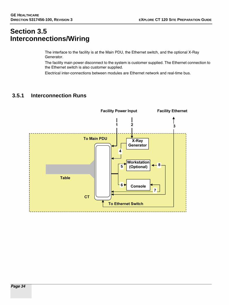
The interface to the facility is at the Main PDU, the Ethernet switch, and the optional X-Ray Generator.
The facility main power disconnect to the system is customer supplied. The Ethernet connection to the Ethernet switch is also customer supplied.
Electrical inter-connections between modules are Ethernet network and real-time bus.
3.5.1 Interconnection Runs
5
6
8
7

GE HEALTHCARE
DIRECTION 5317456-100, REVISION 3 EXPLORE CT 120 SITE PREPARATION GUIDE
Page 35
CABLE RUN LENGTHS
GE Supplied Cables
Between Facility and System:
Run # GE Part Number Description Actual cable length
1 5325025 Facility to Main PDU 25ft
7.62m
2 2411913-5 Facility Ethernet to Ethernet switch
50ft
15.24m
Between Modules:
3 5255208-3 (Generator Communication Cable (D-SUB 15)), 5214670-2 (Generator-Tube Tube Ground Cable), 5272068-2(X-ray Tube Stator Cable), 5265721-2(High Voltage Cathode Cable), 5265721-3 (High Voltage Anode Cable), 5255209(Generator DIO Cable (D-SUB 25))
X-Ray Generator to CT system
20ft
6.096m
4 Main PDU to optional PCI Analysis Workstation
50ft
15.24m
5 5245036 Main PDU to Operator Console
50ft
15.24m
6 2411913-4 Ethernet switch to Console 50ft
15.24m
7 Ethernet switch to optional PCI Analysis Workstation
50ft
15.24m

GE HEALTHCARE
DIRECTION 5317456-100, REVISION 3 EXPLORE CT 120 SITE PREPARATION GUIDE
Page 36
This page is intentionally left blank

GE HEALTHCARE
DIRECTION 5317456-100, REVISION 3 EXPLORE CT 120 SITE PREPARATION GUIDE
Page 37
Chapter 4Before Equipment Delivery
Section 4.1 Delivery/Shipping Considerations
4.1.1 Communicating CT 120 Site Layout to GE
A drawing of the eXplore CT 120 site’s layout must be provided to your GE representative prior to equipment delivery. Typically, the layout is provided in a diagram format and includes the information below.
• Height, width and depth of all access path hallways and elevators (i.e. route from receiving area to designated room), which includes the following:
- height and width of all doorways and their location (note any obstructions like self-shutting door mechanisms)
- height, width and depth of all elevators (note the number of doors and the location of the panel)
- width of all sharp (90°) turns in the hallways
Doorways
Elevator Interior
Elevator Door

GE HEALTHCARE
DIRECTION 5317456-100, REVISION 3 EXPLORE CT 120 SITE PREPARATION GUIDE
Page 38
• Scan room dimensions, including:
- width and depth of room layout
- size and location of all doors and windows
- location of all electrical receptacles, with circuit numbers
- location of all telephone/network receptacles
- location and size of all conduits, floor ducts and raceways
• Equipment room dimensions (if required), including:
- width and depth of room layout
- size and location of all doors and windows
- location of all electrical receptacles, with circuit numbers
- location of all telephone/network receptacles (note the bandwidth of the network)
- location and size of all conduit, floor ducts and raceways
- material of flooring and flooring thickness
• CT 120 equipment placement/orientation
• Non-GE equipment placement/orientation.
4.1.2 Equipment Handling & Storage
The CT 120 is packed for van shipment with minimum tear-down of components. It consists of approximately 4 shipping crates (one for the CT, one for the Table, one for miscellaneous components, and one for the X-Ray Generator).
The CT 120 system is not designed to tolerate excessive mishandling, including dropping, shock, vibration, tipping or hoisting. The CT Gantry, Operator Console, and Specimen Table must NEVER be dropped.
NOTICEEquipment
DamagePossible
A drop from a height greater than one half inch (½”) may induce structural damage to the frame or other major components. Damage resulting from a drop (e.g., bent frame, misalignment) may not be obvious until after system installation is complete.
Hall
Hall

GE HEALTHCARE
DIRECTION 5317456-100, REVISION 3 EXPLORE CT 120 SITE PREPARATION GUIDE
Page 39
The CT 120 system — including Gantry, Operator Console, and Specimen Table — is not designed to tolerate the excessive shock or vibration that may occur during unloading. For example, rolling the Operator Console across a “washboard” style ramp may vibrate components to the extent of loosened or broken connections, etc. Damage resulting from shock or vibration (e.g., monitor, CD-ROM, or hard-drive failure) may not be evident until after system installation is complete.
All system components must remain upright at all times, and must not be tipped. Nor should the Gantry be hoisted. The Gantry should be moved by rolling on dollies only. Movement through hallways, doorways, elevators, etc., must be done without tipping or lifting the Gantry.
STORAGEIf the CT 120 system is to be stored before installation, store in a warehouse. Protect the system from weather, dirt and dust. Storage temperature should not exceed 0° to +100° F (-18° to +40° C). Maintain relative humidity (non-condensing) between 30 and 60%. Do not store the system for more than 90 days.
4.1.3 Site Environmental Considerations
DUST/DIRT CONTAMINATIONThe CT 120 system — Operator Console, Specimen Table and Gantry — is highly susceptible to airborne contaminants, especially concrete and drywall dust. Due to the possibility of contamination, this system should NEVER be installed in a construction site. Any site with unfinished floors, walls or ceilings is considered a construction site, and is not suitable for system installation.
CHEMICAL CONTAMINATION Wet film processors must never be installed in the same room as the scanner due to the possibility of chemically contaminating the components. Such chemicals can contribute to increased equipment failures, increased system downtime, and decreased reliability. Film processor equipment installation must meet the manufacturer’s requirements (e.g. ventilation specifications) and all applicable national and local codes. Also, consideration should be given to the location of this equipment and chemical fumes relative to human contact as it relates to the location of this equipment and chemicals in the scan room.
4.1.4 Individual Components
CT 120 GANTRY CONSIDERATIONSTo avoid dropping the Gantry, dock-to-dock shipment is recommended. Other methods are accept-able provided that the system is not dropped or otherwise mishandled. For example, the system may be moved via a flat-bed wrecker or by rolling it across smooth sidewalks or other paved surfaces.
The Gantry’s covers are shipped pre-mounted to the system (although the covers may be removed once unpacked, if needed, to transport the Gantry to its final location).
The Gantry is mounted on elevating casters. Once unpacked, the casters are elevated and the Gantry is rolled to the scan room.
GE HEALTHCARE
DIRECTION 5317456-100, REVISION 3 EXPLORE CT 120 SITE PREPARATION GUIDE
Page 40
Door Openings
Clear door openings for moving equipment into building must be 42 X 82 in. (1067 X 2083 mm) minimum, if there is an 8 ft. (2438 mm) corridor width.
Elevator requirements
To move the CT 120 from the receiving location to the scan room, consider elevator capacity and size. By removing covers from the Gantry, the width/length and elevator depth requirements are reduced. Contact a representative of elevator manufacturer if weight exceeds elevator capacity.
For alternative lifting arrangements and instructions, contact GE Installation Support Services.
TABLE CONSIDERATIONSTable covers are shipped mounted to the specimen table and the table is attached to the CT gantry. The table is mounted on caster wheels.
OPERATOR CONSOLE CONSIDERATIONSThe Operator Console is shipped without the keyboard table installed.

GE HEALTHCARE
DIRECTION 5317456-100, REVISION 3 EXPLORE CT 120 SITE PREPARATION GUIDE
Page 41
Section 4.2 Pre-Install Review
4.2.1 Pre-Install Checklists
GE CUST
Y N Y N DATES
Project schedule verified with contractor, facilities department, and GE?
Construction completion date matches delivery date?
Power & Ground survey complete, date____________________ contact____________________
Delivery date is scheduled for:____________________
First Use date is scheduled for:____________________
Applications training dates: On Site scheduled for:____________________
GE CUST GENERAL / SITE REQUIREMENTS
Y N Y N Must be completed 5 weeks prior to the delivery
Final drawings distributed to the contractors and reviewed with GE?
Have any additional requirements or questions of the install been discussed with GE?
Final print(s) "signed off’ that approve equipment layout / orientation?
Person assigned to review and verify that all installation requirements are met?
Have the specified site requirements been discussed with the contractor? All work by contractors must be completed prior to GE delivery.
Requirements?
- Air Conditioning
- Electrical
- Structural
- Environmental
All 3rd party vendors identified, notified and scheduled?
Will existing network and cable drops reach new locations / requirements?

GE HEALTHCARE
DIRECTION 5317456-100, REVISION 3 EXPLORE CT 120 SITE PREPARATION GUIDE
Page 42
GE CUST EQUIPMENT
Y N Y N Must be completed 5 weeks prior to the delivery
Order reviewed for completeness and compatibility with existing equipment?
Has the location of any peripherals been determined and planned accordingly with GE representatives?
List peripherals_____________________________________________________________
Have any additional services to be provided by GE been discussed and agreed upon?
GE CUST NETWORKING
Y N Y N Must be completed 5 weeks prior to the delivery
Have IP addresses and Host Names been obtained?________
CT 120 service telephone line(s) identified and installed?
Network installed? Network jacks installed and tested?
Network options ordered______ DICOM print______PCI Analysis Workstation______
Test network connections and Internet connectivity?
GE CUST OTHER
Y N Y N Must be completed prior to the delivery
Arrangements made in the schedule to allow for remodeling, if required? (i.e. wall, floor, or ceiling repair work, painting, other cosmetic finishes)
Have arrangements been made to clean the floor after any previous equipment removal and prior to install?
Delivery route identified and verified with proper personnel?
Appropriate arrangements made with traffic for delivery?
Will acceptance testing or Biomedical testing be required?
Trash bins available for the removal of paper, boxes, etc. during installation?
Waste disposal of packaging materials arranged?
Contact person identified at customer site?