exploration report for
TRANSCRIPT

42A99NWM26 2.6099 COULSON010
MAUDE LAKE GOLD MINES LIMITED
EXPLORATION REPORT
FOR
COULSON CLAIM GROUP
COULSON TOWNSHIP
LARDER LAKE MINING DIVISION
RECEIVED
MAY 14 1985
MINING LANDS SECTION
R. A. Bennett, MSc., PEng May 7, 1985.

MAUDE LAKE 60LD MINES LIMITED
EXPLORATION REPORT - COULSON CLAIM GROUP
INTRODUCTION
Preliminary exploration work was completed over Maude Lake Gold Mines Ltd.'s COULSON GROUP of claims during the Fall and Winter of 1984. Gridding, magnetometer, radiometric, and two electromagnetic surveys were done to help characterize the underlying formations and locate potential target areas.
The property consists of 16 contiguous staked mining claims numbered: L. 737479 through L. 737482 inclusive 14 claims) L. 737493 through L. 737496 inclusive 14 claims] L. 787085 through L. 787092 inclusive (8 claims)
and are registered in the name of Maude lake Gold Mines Limited, 300 ElmStreet West, Sudbury, Ontario, P3C1V4.
The claims are located along the southwestern boundary of Coulson Township, Larder Lake Mining Division (NTS:42A9W), approximately 8 miles north-northeast of the Town of Matheson. Access to the GROUP is by Highway l O l east from Matheson to the Beatty-Carr Township boundary road, and then north, east, and north again along all-weather gravel town ship roads to within l miles of the claims. An old winter tractor trail extends to the center of the GROUP. The COULSON GROUP lies immediately north of Maude Lake's Main Group.
A property and general location plan is provided overleaf.
GENERAL 6EOL06Y l HISTORY
The general geology of Coulson Township is illustrated and briefly described on ODM Preliminary Map # PI57 by E. Leahy and R. Ginn, 1961. The prop erty has approximately 30* bedrock exposure and is shown to be underlain by a north-facing pile of Precambrian mafic lavas which are cut by a few north-trending Matachewan diabase dykes, and northeast striking Algoman porphyry dykes. An old pit is shown on PI 57, and a few more were located during the course of the exploration work.
The only previous exploration on record for the property is that completed by Maude Lake during 1982 on the 4 southwestern-most claims. This work included geological mapping, magnetic and VLF-EM surveys.

Scale 250,000
It ©l[44346
"v*r . T1 v "i* v * vt* 0 1* 0 * 9 ?* 6 "fr 0 1 1? 6"
u
| 801695r; - -
804694
.10Scale: r- 1/2mile
L li
l604700 i 604701l""" "T
l 804715 i 804716
604714 - 804717——— f
804713
MAUDE LAKE G OLD MINES LIMITED
PROPERTY Se LOCATON PLAN
couLSon CLflirn GROUP
Coulson Twp., Larder Lake Mining Div. May?. 1985

MAUDE LAKE 60LO MINES LIMITED page 2.
EXPLORATION WORK
A grid of picket lines totalling 13.5 miles and 2.0 miles of baseline was cut over the GROUP during October and November 1984 by Maude Lake personnel. The baseline strikes east-west and follows the Beatty-Coulson Township boundary. The picket lines strike due north and are spaced at 400 foot intervals. Pickets were chained and set every 100 feet along all the cut lines. A Base Station was established at 24W on the Baseline for geophysical survey tie-in purposes.
MAGNETOMETER SURVEY
A magnetometer survey was completed over the claims by W. Fuller during November 1984 using a Sharpe Intruments MF-1 Fluxgate Magnetometer. Readings were taken every 100 feet along all the cut lines for a total of 702. Daily magnetic readings were tied to the base station and corrected for diurnal drift. In addition, secondary base stations along the baseline at each line were re-read as each loop was completed. All the readings were adjusted to correspond to those magnetic results on the adjoining Main Group.
The results of the magnetometer survey are plotted on Map COM-002 that accompanies this report. Diurnal variations were a maximum of 120 gammas for any given day and 200 gammas for the entire survey. A summary of the MF-1 specifications and operation procedures is appended.
The range of magnetic susceptibilities for the claim GROUP fall between -4000 and +2950 gammas, with the average background being 780 gammas. Three north-striking magnetic highs along lines O, 8W, and 48W are interpreted to be caused by diabase dykes. A diabase dyke was seen in outcrop at Line O on the baseline. Two other north-trending features on Lines 20W and 44E may also be due to diabase.
The several narrow, sharp westerly-trending magnetic highs that parallel the volcanic stratigraphy could be caused by concentrations of magnetic oxides or sulphides within the flows or along flow tops. Most of these anomalies occur over or near outcrop. The broad, flat magnetic trends in the western, north-central, and eastern portions of the GROUP occur over low, swampy areas and likely reflect more the depth of overburden than the underlying geology.

l l l l l l l l l l l l l l l l l l
MAUDE LAKE 60LD MINES LIMITED page 3.
ELECTROMAGNETIC SURVEYS
Two VLF-Electromagnetic surveys were completed over the claims during November and December 1984 by W. Fuller and N. Bussolaro. The Phoenix VLF-2 EM Unit was used and readings were taken every 100 feet along all the grid lines. At each station, the dip angle, the phase angle, and the field strength were measured. The first station (FI J used was that a Cutler, Maine [24.0 KHz] to test for easterly striking structures and/or conductive zones. The Cutler station was usually read on Tuesday, Wednesday, and Thursday. The second station [F2l used was that at Annapolis, Maryland (21.8 KHz] to test for northerly striking structures and/or conductive zones. The Annapolis station was usually read on Friday, Saturday, and Monday. The claims were traversed separately for each survey. All the dip angles are plotted at l "-40 degrees. The field strength readings were tied into the base station on a daily basis.
The results of the two electromagnetic surveys are plotted on: for FI - Map "COV-003 - Cutler, Maine (24.0 KHz] for F2 - Map 'COV-004 - Annapolis, My 121.8 KHz]
that accompany this report. For each survey, 702 stations were read. Asummary of the VLF-2's specifications is appended.
The cross-over anomalies have been categorized into two groups; those having high field strengths, and those with low field strengths. As a general rule of thumb for interpreting VLF-EM data, high field strength cross-over anomalies usually reflect bedrock features whereas low field strength anomalies typically are caused by overburden contrasts.
Map # COV-003For the FI survey, several strong VLF-EM anomalies were found. Anomaly l traverses half the property and corresponds directly with a rusty shear zone found in outcrop on Line 16W. Anomaly 2 parallels anomaly l and likely has a similar cause. Anomalies la and 2a, although seeming as strike extensions, both have low field strengths, fall along drainages, and are interpreted to be caused by overburden contrasts. Anomalies 3,4 and 5 all strike northwesterly, approximating the strike of the volcanic stratigraphy. These are interpreted to be caused by sheared and/or mineralized flow top breccias. Anomaly 4 is associated with a coincident mag high and may be caused by pyrrhotite-rich flow tops. The four single-line cross-overs all fall in overburden areas and their causes are unknown.

l l l l l l l l l l l l l l l l
MAUDE LAKE 60LD MINES LIMITED pige 4.
Map * COV-004For the F2 station, only one 2 line cross-over and several isolated single-line anomalies were found. Anomaly 6 strikes northwesterly and may be due to sheared flow top breccia. The single-line cross-over at 24W, 7N falls along anomaly l and reflects the shear zone. The remaining single-line cross overs have unknown causes.
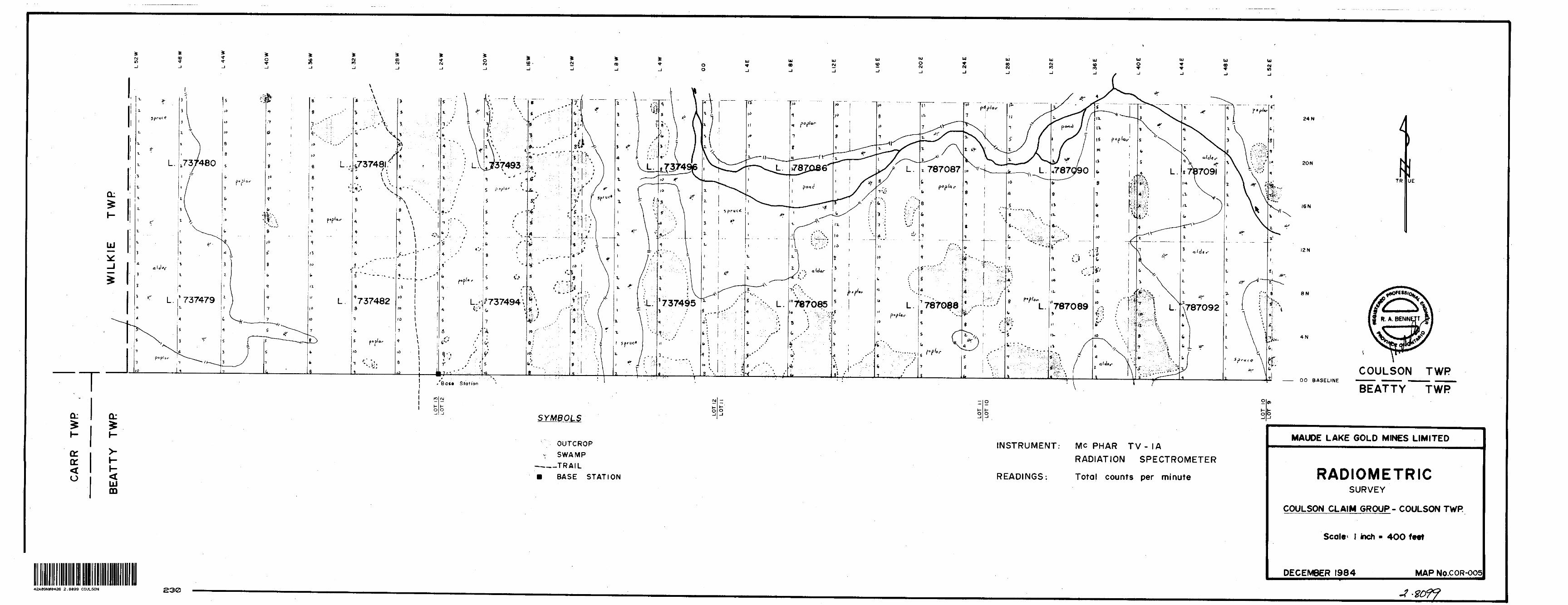
RADIOMETRIC SURVEY
A radiometric survey was completed over the GROUP during November 1984 to assist the eventual geological interpretation and to test for potassium-rich felsic intrusions and/or alteration zones that can be associated with gold mineralization events. A McPhar TV-1A Radiation Spectrometer was used and the total field readings were taken every 100 feet along ail the grid lines. In all, 704 readings were taken. All the readings were tied into the base station and corrected for diurnal drift using the time-linear method. The general topography and outcrop areas were also charted. A summary of the TV-1 A's specifications is appended.
The total field readings ranged from l to 14 counts per minute for the sur vey area iMap "COV-0051. These can be grouped into distinct populations based on the surface conditions. Low, wet areas having alder and spruce swamps, or open beaver ponds always had the lowest readings [ l to 3 cpm ]. Areas of outcrop returned readings between 4 and 8 cpm. The highest readings [ 8 - H cpm j always fell over areas with poplar bush where the lacustrine clay deposits are closest to the surface. One potassium- enriched outcrop area at 40E, 5N was found and should be investigated further.
CONCLUSIONS AND RECOMMENDATIONS
Preliminary exploration work that included magnetic, radiometric, and two electromagnetic surveys was completed over Maude Lake Gold Mines' COULSON GROUP of claims in southwestern Coulson Township. The results have better defined the geophysical character of the underlying geology and outlined specific target areas that should be further investigated by detailed prospecting and geological mapping.
l l
Matheson, Ontario R.A. BenrettrMSc., PEng. 4 maps, 3 appendices May 7, 1985.

l l l l l l l lriiiiiiiiii
APPE
ND
IX
MF
'-l M
AG
NETO
METER
S" cr
is
""
•o
Ss'B
O
-g
•i ~*03*C
O
o
o
o
^i
*C
5s
'a n
" iO
c
CD r:
O
cj
E
o5f
S
B G
so
oSoa.
OoCO
oE
•u M
. .H
-
•o
oC)
c
o
E
ra
oO)
' o
j 2-
Era
-i
l^
"
gS
S S
CO
3
—
2 s
o
S
.HC
O
~
I(A
O
•o
o
Ec: uc
o
eCO
o
•a
i -sra
~-
rao
-S
oco
-oco
o
v- "TO
i i
5
to
^
ora
*S
* 3
23
l i
s lsi
5
GO
g
Q*-
Ss stZ
s-
i i
s -
2
~
S35
g
S
i i g
i l
o.
o
CO
^
^
ra S
t
Jo
o
O
CO
o
oQ.
O
"
6-*
•-s:3=
0
"ra o
M
^
V
i o
Q.
ESO
r;
c^ ^
*oE
S
H
5
E
c
S
E
E
H*^
*TT
er
.-3 I-S
CC
t3
C
J
Ci
GC
o
CD cr. o o
O
CJ5 C
D
Ci
Oo
o o
o o
" ~
*
X

DESCRIPTION OF FLUXGATE MAGNETOMETER MODEL 37 F-J.
ra i f j ii*W' 1. :,,\ ^ t a- w
FIGURE A1
2
FIGURE B1
2
3
RANGE SWITCH
METER SCALE
indicating gamma values in ranges of 100 K, 30 K, 10 K, 3000, 1000.upper scale indicating 0-1000l50 divisions)
~ lower scale indicating 0-3000 (GO divisions) red arc for battery check
3 MAIN SWITCH — showing the following steps:OFF Battery check
CIRCULAR LEVH
for roup,h levelling the instrument
LATITUDEADJUSTMENTSWITCHLATITUDE ADJUSTMENTBATTEItY CAliLE AND CONNECTORBATTERY PACK
in steps
fine
For transportation instrument
attachable to
E. J. SHARPE INSTRUMENTS OF CANADA LTD.
P.O. Cox 279, Y/illowilalc, Ontario
npn.'Yrr\ IK) CANADA

MODEL MF-1 FLUXGATE MAGNETOMETERJpcrotion of the Motor1.) Remove all magnetic objects from operator's person, e.g. keys, coins, buttons, etc,
Zippers should be non-magnetic.2.) Connect Battery Cable, Figure 6, to magnetometer receptacle on bottom of main hous
ing. This connection must be secured by lock-ring. A User, oattery pack (Fig. 5) either in back pocket or on belt behind operator. Switch on Main Switch (Fig. 3) to first position, which is the battery check. Indicating rr.eter needle should rest within red arc. Replace batteries if reading below red arc.
i. i L.n;itude Adjustment -To adjust the latitude setting toread O gammas is a simple operation.j. After indicating meter needle (fig.2) shows voltage okay, switch Main Switch(Fig.S)
•.c next position which is the positive reading with the Range Switch (Fig. 1) set at :he '.OOK step. (100,000 gamma range)
."'.If needle goes full arc to left past O, switch main switch (Fig. 3) to last position which is the negative reading range.
c. Figures 10 and 9 indicate the latitude adjustment controls - Coarse control is Fig. 1C and Fine control is Fig. 9. If scale reading is more than t 7 ,000 gammas rotate :oarse control (Fig. 10) in steps of 7,000 and switch range down to more sensitive .•ange until scale is reading less than i 7,000 gammas. Remove protection cap on rine control (Fig. 8) by pulling straight off. Then rotate fine control switch (Fig. 9) cr.til scale reading is O gammas. Check reading by switching main switch from positive to negative (or vice versa) to ensure O reading both polarities. Replace fine control protection cap.
6.) Calibration - This meter is calibrated at the factory prior to delivery. Field tests show that only by severe misuse (i.e. constant dropping, rough handling, improper shipping) can the calibration of this instrument be effected. It is therefore not necessary to re calibrate in the field and if through misuse calibration becomes necessary, the meter should be returned to the factory. *AII parts are guaranteed against defect for a period of one year and will be replaced free of charge.
"This guarantee does not apply to batteries or the connecting cable.7.) Trouble Shooting - Under normal conditions the only field problem will be batteries or
the connecting cable. If after completion of step (4) under "Operation of the Meter" !he meter still does not indicate voltage, check cable for faulty connection or broken cable. If after this procedure, meter still does not indicate current, return unit immedi ately to your supplier or directly to the factory.
Regional Latitude SettingsNormally each unit is pre-set at the factory for the Northern Hemisphere. However, if the uni: is required for Equatorial or Southern Hemispheric regions, the unit will be pre-set at the :actory for these areas. If a unit is going from one of the above regions to another, re;,; instructions will be supplied on request. Field Procedure!,'; .-c-is c; Base Control station. This station should be selected in relation to one or
..•:th ot two things.\. G eneral magnetic background (i.e. not anomalous) if possible. 2. Accessibility in relation to area being surveyed.
2.) Se: !i:.g,ietometer toread between O and 200 gammas. (For contouring and to avoid small negative readings, an arbitrary value of I000-800gammas should be added to all readings.
3.) For elective diurnal control, control stations should be permanently marked and read*•t-s should be taken at the same height and location each time; a simple method is to ..ve the control stations' pickets hammered into the ground with the top about waist
::i,ght. Rest the probe end of the magnetometer on the top of the picket. In barren country,a mound or large piece of rock or some other material should be used.
4.) Continue survey the same as any other method of magnetic surveying.5.) Remove and replace Silica-Gel (Fig.7) when deteriorated. The silica gel is located
in the removable probe housing.The Silica bag should not be placed on the bottom of the probe housing.
D ' De not pass powerful magnet closer than l foot to instrument. l d uring winter operation, batteries should be kept in pocket or under parka. •""iVarning: - Do not leave batteries in battery case when'unit is being stored. Always be
:,e sure meter is turned off after use. Disconnect battery cable when meter not in use.

l
l
l
l
l
l
l
l
l
l
l
l
l
l
l
l
l
l
l
APPENDIX 2
Electromagnetic Unit
Lightweight, low battery drain, rugged, simple to operate
Two independent channels
Each channel may select any station between 14.0 and 29.9 kHz
Single crystal used for all frequencies
Locking clinometer provides tilt-angle memory
Superheterodyne detection and digital filtering provide extremely high selectivity and noise rejection
Military and time standard VLF transmitters are distributed over the world. These stations are used for geophysical EM surveying thus eliminating the need for a local trans mitter and permitting one-man operation.
To ensure that a station excites the prospec tive conductor, two stations at approximately right angles are used during o survey (see data on back).
The choice of 160 frequencies in the range 14.0 to 29.9 kHz permits the use of a local EM trans mitter when no suitable regular VLF station is available.
PHOENIX GEOPHYSICS LIMITEDGeophysical Consulting and Contracting, Instrument Manufacture, Sale and Lease.
Head Office: 200 Yorkland Blvd. Wlllowdale, Ont., Canada M2J 1R5. Tel: (416) 493-6350310-885 Dunsmuir St. Vancouver, B.C., Canada V6C 1N5. Teh (604) 684-2285 4690 Ironton St. Denver, Colorado, U.S.A. 80239. Tel: (303) 373-0332

Specifications
'
ParamelflkMeasured
Frequency Selection, Front Panel
l Frequency Selection, Internal
Detection And Filtering
I Orientation and magnitude of the major and minor axes of the ellipse of polarization.
: Dual channel, front panel selectable (FI or F2) each with Independent precision 10-turn dial gain control.
: FI and F2 can be selected by internal switches within the range 14.0 to 29.9 kHz In 100 Hz Increments.
: Superheterodyne detection and digital filtering provide o much narrower bandwidth and thus greater rejection of Interfering stations and 60 cycle noise than conventional
All of the established stations may be (elected, or alternatively, a local VLF transmitter may be used which transmits at any frequency in the range 14.0 to 29.9 kHz.
• Meter Display
• Audio
Clinometer
—1 Batteryg}
Temperature RangeH1 Dimensions
Weight
Field Data
receivers.
: 2 ranges: 0 to 300 or 0 to 1000. Background is typically set at100, Meter is also used as dip angle null indicator and batterytest.
: Crystal speaker. 2500 Hz used os null indicator.
: +90", +0.50 resolution. Normal locking, push buttonrelease.
: One standard 9v transistor radio battery. Average lifeexpectancy - 1 to 3 months (battery drain is 3 mA)
S -40" to + 60 0 C.
: 8 x 22 x 14 cm (3 x 9 x 6 inches).
: 850 grams (1.9 pounds).
VLF Station Frequency
Bordeaux, FranceOdessa (Block Sea)Rugby, U.K.Moscow, U.S.S.R.Yosomoi, JapanHegalond, NorwayCutler, MaineSeattle, WashingtonMalabor, JavaOxford, U.K.Paris, FranceAnnapolis, MarylandNorthwest Cape, AustraliaLouluolel, HawaiiBuenos Aires, ArgentinaRome, Italy
(kHz)
15.115.616.017.117.417.617.818.619.019.620.721.422.323.423.627.2
l l l l l l l l l l
The results below illustrate the need for using two orthogonal stations when the strike of the prospective conductor is not well-known. The dip angle and amplitude data measured using station NLK in Seattle, Washington, show only a very weak anomaly associated with the two conductive sulphide zones at Cavendish, Ontario.
The results obtained using Cutler, Maine reveal a more prominent anomaly, but the best response was obtained using Annapolis, Maryland since the station lies almost due south and the transmitted electromagnetic field is thus maximum-coupled with the North-South trending conductors.
JO'
10-
oir
•so".140'
ItO-
Z20'
210-
200'
190'
HO
170-
HO-
ISO-
140-
150-
120-
110'
100'
PHOENIX GEOPHYSICS LIMITEDVLF-RADIO EM SYSTEM LINE C CAVENDISH TEST AREA
——— 0WE8T O IPi0EAST DIP
0 NORTH DIPjQsOUTH DIP
Station MSS Annopolit, Md
Station NAA Cutlir, Moini
Station NIK Stott!*, Winnington

APPENDIX 5
McPHAR TV-1A Radiation Spectrometer
A 3-channel instrument for reconnaisance use
Both meter and audio reading
Four count scales
Trigger on-off switch
Functional pistol design
Lightweight
Model TV-1 A is a three channel, integral type radiation spectrometer. Measure ments are based on the spectral characteristics of gamma radiation from radioactive elements. Selection of the operating threshold is made by means of the threshold selector switch.
The instrument is designed primarily for reconnaissance. The total count position provides for maximum sensitivity. Addi tional thresholds however, provide the
capability to differentiate between gamma radiations emanating from daughter elements of uranium and thorium and provide quantitative Infor mation relating to each.
The meter is calibrated to display zero to 100 counts per minute. A four position scale multiplier switch provides four full scale ranges of 100,1,000,10,000 and 100,000 counts per minute. A fifth position on this switch is employed to
test the condition of the batteries.The variable time constants are tied in with the threshold selector switch. In the total count (maximum sensitivity) posi tion, a fast or slow time constant may be selected. In the upper thresholds (lower net count), the long time constant only, is in effect.The detecting element is a 1V4 by V/z inch sodium iodide crystal coupled to a photomultiplier tube. These are hermet-

Field use is convenient with leather holster
l l l l l
ically sealed, magnetically shielded and mounted in the forward end of the scintillometer housing. A speaker provides a variable pitch
output with changing radiation levels. A speaker control, mounted on the top of the instrument, can be used to adjust the pitch for any given level of radiation.
TV-1 A spectrometer comes complete with a leather holster, thorium calibrating source and a foam fitted attache case.
Specifications •~Measurement Ranges: Four switch positions provide full scale counts per 10Mminute of 1 00, 1 ,000, 1 0,000 and 1 00,000.
•00
Time Constant: Threshold Ti: 1 and 10 J seconds. Thresholds T2 and T} : I 10 seconds. t , coSpeaker: Variable pitch output governed * *o by radiation intensity.Temperature Range: -35 degrees to -f 55 degrees C. 't
••^•V
V i \
^ \ f\ 1\
—— M
\r
:X\y
X"\
Tt"t
\
/N
W
A — '-i—•- -V ^r/'V \ \
\\
- WM4M ...,.
- *0
'j
ttHVM
1 ,,A-\
— .
Detector Crystal: Nal (T) W" x 1V4" (43 cu. cm.) and matched photo-multiplier hermetically sealed.Battery Supply: Two "C" size flashlight cells located in handle. On-off control by either trigger or slide switch.
Gtrnnl Aiy I
H 10lv
NrvfllOrno'TIMli
Voltage Regulation: Internally generated high and low voltages are highly regu lated down to Vi i nitial battery voltage.Accessories: Leather belt holster,
thorium calibrating source, spare batteries, instruction manual, foam fitted attache case.Weight: 3 pounds.
McPhar Instrument Corporation Head Office:55 Tempo AvenueWillowdale, Ontario, Canada M2H 2R9 Tel: {416) 497-1700 Telex: 0623541 Cable: McPHAR TOR
Sales agents In:Africa, Asia, Australia, Europe, North 6\ South America
Contact McPhar Instrument Corp. head office for the agent in your area.

42Ae9NWM26 2 .8099 COULSON
Mining Lands Section
Control Sheet
900
File No
TYPE OF SURVEY
MINING LANDS COMMENTS:
GEOPHYSICAL
GEOLOGICAL
GEOCHEMICAL
EXPENDITURE
Signature of Assessor
Date

Minis|iatu
* Resources
Report of Work(Geophysical, Geological, Geochemical and Expenditures)
The Mining Act
Instructions: — Please type or print.- If number of mining claims traversed
exceeds space on this form, attach a list.Note: — Only days credits calculated in the
"Expenditures" section may be enteredin the "Expend. Days Cr." columns.
- Do not use shaded areas below.
.- *** s,Township or Area
(JlF-t**,Prospector's Licence No.
T u eiClaim Holder(s)
Address
Survey Company
Name and Address of Author (of Geo-TechnicaTreport)
' | Date of Survi
___________i Day l Mo. l
y (from fit to)
Yr. j Day | Mo. | Yr.
^2 2 - 76?Z.
Total MllM of line Cut
Credits Requested per Each Claim in Columns at rightSpecial Provisions
For first survey:Enter 40 days. (This includes line cutting)
For each additional survey: using the same grid:
Enter 20 days (for each)
Man Days
Complete reverse side and enter total (s) here
Airborne Credits
Note: Special provisions credits do not apply to Airborne Surveys.
Geophysical
- Electromagnetic
- Magnetometer
- Radiometric
2mM/-^Geological
Geochemical
Geophysical
- Electromagnetic
- Magnetometer
- Radiometric
- Other
Geological
Geochemical
Electromagnetic
Magnetometer
Radiometric
Days per Claim
2020AO10
Days per Claim
Days per Claim
Expenditures (excludes power stripping)Type of Work Performed
Performed on Claim(s)
Calculation of Expenditure Days Credits
Total ExpendituresTotal
Days Credits
InstructionsTotal Days Credits may be apportioned at the claim holder's choice. Enter number of days credits per claim selected in columns at right.
Date Recorded Holder or
Certification Verifying Report of Work
Mining Claims Traversed (List in numerical sequence)
Total number of mining claims covered by this report of work.
l hereby certify that l have a personal and intimate knowledge of the facts set forth in the Report of Work annexed hereto, having performed the work or witnessed same during and/or after its completion and the annexed report is true.
Name and Postal Address of Person Certifying
8.6.4 s ire- 57 A** i O*vr.Certified Cert/fi/d by (Sigp*ture)
W,
1362 (81/9)

REGISTERED
May 7, 1985 Report of Work
Maude Lake Gold Mines United 300 Elm Street West Sudbury* Ontario P3C 1V4
Dear S1n
RE: Mining Claims L 737479, et al, In the Township of Coulson
I have not received the reports and maps (In duplicate) for the Electromagnetic, Magnetometer and Radiometric Survey on the above-mentioned claims.
As the assessment "Report of Work11 was recorded bythe Mining Recorder on March 18, 1985, the 60 day period allowedby Section 77 of the Mining Act for the submissionof the technical reports and maps to this officewill expire on May 17, 1985.
If the material 1s not submitted to this office by May 17, 1985, I will have no alternative but to Instruct the Mining Recorder to delete the work credits from the claim record sheets.
For further Information, please contact Mr. Arthur Barr at (416)965-4888.
Yours sincerely,
S.E. YundtDirectorLand Management Branch
Whitney Block, Room 6643 Queen's Park Toronto, Ontario M7A 1W3 Phone:(416)965-4888
A. Barntoc
cc: Mining RecorderKirkland Lake, Ontario
End,
cc: R.A. Bennett R.R.I4Site 37, Box l Sudbury, Ontario P3E 4M9

Ontario
Ministry of Natural ResourcesGEOPHYSICAL - GEOLOGICAL - GEOCHEMICAL
TECHNICAL DATA STATEMENT
File.
TO BE ATTACHED AS AN APPENDIX TO TECHNICAL REPORTFACTS SHOWN HERE NEED NOT BE REPEATED IN REPORT
TECHNICAL REPORT MUST CONTAIN INTERPRETATION, CONCLUSIONS ETC.
Type of Survey(s) Township or Art-a
Claim Holder(s)
Magnetometer, VLF EM, VLF EM, Radiometric
nnm.SDN TOWNSHIP
Maude lake Gold Mines Ltd300 Elm St. West, Sudbury, Ont
Survey Company R.A. Bennett. Consulting GeologiiAuthor of Report R. A. Bennett, PEncj.Address of Author RR4. Site 37. Box l, Subury, OntCovering Dates of Survey Pot 3, 1984 to Dec 15, 1984
{(incoming to office) Total Miles of Line Cut 1S. R m -i
SPECIAL PROVISIONS CREDITS REQUESTED Geophysical
-Electromagnetic^^. ENTER 40 days (includes * ^^line cutting) for first -Magnetometer^^, survey. —Radiometric——g^. ENTER 20 days for eaclnd VLF -Other——————g^. additional survey using Geological——-—-. same grid.
DAYS per claim
Geochemical.AIRBORNE CREDITS (Special proviiion credit* do not apply to airborne surveys)
Magnetometer. .Electromagnetic. . Radiometric(enter days per claim)
^f Author of Report or Agent
Res. Geol.. .QualificationsPrevious Surveys
File No. Type Date Claim Holder
MINING CLAIMS TRAVERSED List numerically
L. 737479
• •**************4t****tt**tt***t* *i*A? li*]L*t*V**t*************
737495
737596
t******************4* o* f* v (P& •
787086
787088
787089
787090
787091ti
787092
l
TOTAL CLAIMS
837 (6/79)

GEOPHYSICAL TECHNICAL DATA
GROUND SURVEYS — If more than one survey, specify data for each type of survey
Number of Stations———— f (J c.——————————————————Number of Readings ——. Station interval ' ——————100 feet________Lme spacing______400 feet Profile scale______l" c /fO degrees_________________________
Contour interval _____100 gammas_____^_______^___^__________
Instrument ————SHARPE MF-1 Fluxgate Magnetometer———————————Accuracy - Scale constant 5 gammas———-—---————————————————.
C Diurnal correction method Time Linear___________________________ l . Base Station check-in interval (h™.™) ''4 hours f to 6 flOUTS - ___________
s
w
i—
Base Station location and value Line 2k W On the Baseline.-————-———————-
Instrument Phoenix VLF-EM Unit 2_____________________________
Coil configuration —————————————————————————————————————————————————————
Coil separation ———————————————————————————————————————————————————————————
Accuracy ———————————————————————————————————————————————————-.———— Method: ffl Fixed transmitter D Shoot back O In line D Parallel line
Survey 1=24.0 KHz, Cutler Ma. Survey 2s.21.6 KHz, Annapolis My.(specify V.L. F. nation)
ParametersmMMirprf Dip angle, Phase angle. Field Strength.
Instrument.Scale constant
Corrections made.
^ Base station value and location.
Elevation accuracy.
Instrument ————Method D Time Domain D Frequency Domain
Parameters - On time _________________________ Frequency ————-Off time__________________________ Range ———————
— Delay time ________________________
— Integration time.Power.G Ci
^ Electrode array.
Electrode spacing . Type of electrode

SELF POTENTIAL
Instrument
Survey Method
Cnrrertinns made
Rang*
RADIOMETRIC
Instrument———-Values measured.
McPhar TV-1A Radiation SpectrometerTotal Field Readings
Energy windows (levels) Height of instrument—Size of detector____XOverburden Pond,'swamp, Poplar bush, and Outcrop
Background Count. 7 cpm
by ^-j- inches
(type, depth - include outcrop map)
OTHERS (SEISMIC, DRILL WELL LOGGING ETC.)
Type of survey————————————————————————— Instrument —————————————————————————Accuracy———-————-—————————-—...—————.Parameters measured.
Additional information (for understanding results).
AIRBORNE SURVEYS
Type of survey(s) ———— Instrument(s) —————
Accuracy————^—^(specify for each type of survey)
(specify for each type of survey)
Aircraft used.Sensor altitude.Navigation and flight path recovery method.
Aircraft altitude.Miles flown over total area.
.Line Sparing
.Over claims only-

GEOCHEMICAL SURVEY - PROCEDURE RECORD
Numbers of claims from which samples taken.
Total Number of Samples. Type of Sample.
(Nature of Material)Average Sample Weight——————— Method of Collection————————
Soil Horizon Sampled. Horizon Development. Sample Depth———— Terrain————————
Drainage Development———————————— Estimated Range of Overburden Thickness.
ANALYTICAL METHODSValues expressed in: per cent
p.p. m. p. p. b.
D D
Cu, Pb, Zn, Ni, Co, Ag, Mo, As.-(circle)
Others________________________Field Analysis (.
Extraction Method. Analytical Method. Reagents Used——
Field Laboratory Analysis No.(——————^——
SAMPLE PREPARATION(Includes drying, icreening, crushing, ashing)
Mesh size of fraction used for analysis————
Extraction Method. Analytical Method . Reagents Used ——
Commercial Laboratory (. Name of Laboratory,— Extraction Method—— Analytical Method —— Reagents Used -————
.tests)
.tests)
.tests)
GeneraL General.

r-
\
\ \
\ \ V
\
V\\ \ V
\\
\ \
V
\ \ x \
\ x
\ x
\X O
i
x
\ \
.
0 Vi g

in*OD s O)
OJ (Mi 0 o
ou*-l
UJ 00
UJ N
UJo(VJ
UJ*(MJ
UlOD M
Ul Nro
kiV rt
Ul Ul Id
S?UJ Mm
TQ: Q:
I-
o: ir< o UJ
CD
SYMBOLS
OUTCROP { SWAMP
————TRAIL m BASE STATION
INSTRUMENT:
Contour Interva
SHARPE MF lFLUXGATE MAGNETOMETER
100 gammas
24 N
20 N
(6N
I2N
8N
4N
il
TR UE
00 BASELINECOULSON TWR HATTY TWR"
MAUDE LAKE GOLD MINES LIMITED
MAGNETOMETERSURVEY
COULSON CLAIM GROUP - COULSON TWR
Scale- l inch - 40O feet
DECEMBER 1984 MAP No.COM-002
•?2A09NWe426 2.8099 COULSON 200

in*OD
* O
*
SMK)
CDC\J
*•* CJ
Ofsj (M 00 O
O
til Ulto
Ul (M
UJ (D
UlO (M
U Ul K) (M
Ul (M
Ul ID f*
Ul Id9
u
4ZW
CL
I-
LU
T
v \
y/' i^
Q: Q:
H
a: a:< o UJ
CD
/
7
"•737482\
-
'74;IE
v 7i
x
i* e
7
t;i' "j"
2.3 E \
31*
Ip
l-rw
lt**l
J737493/
V.(f —
l*re
\. *737494\- N ^
7lie
176ais
\ l 7 7
JouJ
/'x
737496
"737s7
7
Z.oW
O
o
o
o
o
i
Z1W
UW
10 Ul
lit*/
tlM
2*
k.
787085
l*/
J587086
li,-J
O
U
d
O
Bat* Station
rt
SYMBOLS
OUTCROP i SWAMP
————TRAIL H BASE STATION
A
INSTRUMENT: Pheonix VLF-2 EM Unit
STATION : Annapolis, Maryland (21.4KHz)
DIP ANGLE SCALE: l inch = 40 degrees
O
Cross -over Anomaly, High Field Strength " " " Low "
24 N
2O N
t6N
I2N
8N
4N
if
TR UE
00 BASELINE
COULSON TWP
"iiATTY TWR
MAUDE LAKE GOLD MINES LIMITED
VLF-EM SURVEY
COULSON CLAIM GROUP - COULSON TWR
Scale- l inch - 4OO feet
DECEMBER 1984 MAP No.COV-004
42A89NW8426 2.8099 COULSON 210

H)
N
Q
S
X)
i
CAR
R
TWP
BE
ATT
Y
TWR
MM
BM
aJ
WIL
KIE
T
WR
CD
H
W
O
~ L S2
W
L 46
W
U44
W
L4O
W
L 36
W
L 32
W
L 28
W
L 24
W
LOT
12
LOTH
LOT
II
LOT
10
O)
H
o
O
CD"*
O
* O
vi
i o
O
C/)
^
2>
H
" i
i m z H
L 2O
W
L (6
W
taw
MX.
—
*
T
- *
rf
l O
^s.
*"
^
fi
H
T'5
' "*
^lX
* ^
s. fc
/tS
X
l-A
-SA
*^|
3 -x
A, A-
/V^
s \;
il v
TL
4W
oo JUBL
6 i
l^/
fi /.^
^ ^
*5 -
5:i
*.
Jt i
*.
*-
X /\
0
O
C.
O
O
Q
Llt
C
LW
E
ill?
Y;
\- y
r i L
o^X
i- t
/N
//^
r- i
? 0
\SA
^ a
*\a
S
? JT
i0
/y
-j
*- -w.
\jri -
^ *-
*- ^
t t/*
^.\
M
x /3
\0 V
C
*
*-
\
-*-
^L
2OC
O r
m
s O
- O
r l
s fo. V
)
O) o m Z
o5*
5.
o —
*
2
O
9.
"D rr i
(D
(Ob
m
x S
x N c
i
•n i m O
) ci
m
LOT
H?
tW f
t *- L
** z
s i
i o*
--*'*
w-
* j;
ra
z
E t
* t
~ t
x*
i ^
^~
; /
f. S
l li?
iK
/A
^i
- K
?*
t t
* s/
y -^
1
—v
xV 2
* ^?
-;
I ?
i i j
e- i
i
i.
9^
Jtv
l
no
28
H r
H'
H
TQ:
o: cr< o UJ
CD
SYMBOLS
OUTCROP v SWAMP
———TRAIL B BASE STATION
INSTRUMENT:
READINGS:
Me PHAR TV- IA RADIATION SPECTROMETER
Total counts per minute
24 N
20 N
16 N
UE
I2N
8N
4N
00 BASELINECOULSON TWP HATTY TWP"
MAUDE LAKE GOLD MINES LIMITED
RADIOMETRICSURVEY
COULSON CLAIM GROUP- COULSON TWR
l inch - 4OO feet
DECEMBER 1984 MAPNo.COR-005
42A39NW0426 2.8899 COULSON 230