exploration games for uml software design -...
TRANSCRIPT
Exploration games for UML software design
Jennifer TenzerT
HE
U N I V E R S
I TY
OF
ED I N B U
RG
H
Doctor of Philosophy
Laboratory for Foundations of Computer Science
School of Informatics
University of Edinburgh
2006

Abstract
The Unified Modeling Language (UML) has become the standard language for the design of
object-oriented software systems over the past decade. Even though there exist various tools
which claim to support design with UML, their functionality is usually focused on drawing
UML diagrams and generating code from the UML model. The task of choosing a suitable
design which fulfils the requirements still has to be accomplished by the human designer alone.
The aim of this thesis is to develop concepts for UML design tools which assist the modeller
in improving the system design and requirements incrementally. For this approach a variant
of formal games called exploration games is introduced as underlying technique. Exploration
games can be defined on the basis of incomplete and imprecise UML models as they occur
frequently in practice. The designer repeatedly plays an exploration game to detect flaws or
incompleteness in the design and its specification, which are both incorporated in the game
definition. At any time the game definition can be incremented by the modeller which allows
him to react to the discoveries made during a play and experiment with new design solutions.
Exploration games can be applied to UML in different variants. For each variant must be
specified how the UML diagrams are used to set up the game and how the semantic variation
points of UML should be interpreted. Furthermore some parts of the game definition may not
be contained in the UML model and have to be provided separately. The emphasis of this
thesis is on game variants which make use of UML diagrams for modelling system behaviour,
especially state machines and activity diagrams.
A prototypical implementation demonstrates how the concepts developed in this thesis can
be put into practice. The tool supports the user in defining, playing and incrementing a game.
Moreover it can compute winning strategies for the players and may act as opponent of the
modeller. As example a game variant based on UML state machines has been implemented.
The architecture that has been chosen for the tool leaves room for extension by additional game
variants and alternative algorithms.
iii
Acknowledgements
Firstly, I would like to thank my supervisor, Perdita Stevens, for her consistent support,
reliability and quick responses – even while she was officially on maternity leave. Thanks
also to the members of my annual PhD review panel Javier Esparza, Kousha Etessami, Don
Sannella and Ian Stark for their advice on this work. On the technical side I would like to thank
the ArgoUML developers for their support of my early attempts to extend their tool, and Martin
Matula for answering some questions about NetBeans MDR.
When I arrived in Edinburgh to start a PhD I did not come unprepared. Thanks to Hartmut
Ehrig, Martin Grosse-Rhode and Uwe Wolter for introducing me to research at the TU Berlin
and their encouragement to do a PhD. I am grateful to the members of the KB administra-
tive and secretarial staff for their help with funding issues and grant applications. I am also
indebted to the DIRC project (GR/N13999/01) funded by the EPSRC for financial support of
this research, and to the Informatics Graduate School for travel funding. During the last year
of my PhD I had the opportunity to work on the DEGAS project (IST-2001-32072) funded by
the FET Project Initiative on Global Computing. Thanks to my colleagues Stephen Gilmore,
Jane Hillston and Valentin Haenel for a very pleasant DEGAS time.
I am also grateful for the support of my family and friends during my PhD. I would never
have finished this thesis without my partner, Bettina Harm, who has prevented me several times
from giving up. Furthermore she has provided endless supplies of liquorice and Kettle crisps
as “brain-food” and created the GUIDE logo. I would like to thank my parents and Brigitte
and Georg Remer for their encouragement by phone and enjoyable holidays. Moreover thanks
to Anne Benoit and Catherine Canevet for all these delicious French meals; Tom Ridge, Dan
Sheridan, Uli Schoepp and Miki Tanaka for some memorable attempts to go clubbing; Ranajit
Majumder for his wild parties; Chris Walton for his DVD-nights; the members of the Edinburgh
University Wind Band for great rehearsals and socials; all friends who never stopped staying in
touch by email, including Sandra Bork, Stefanie Heidbrink, Gesine Klintworth, Solveig Lier,
Jana Schmidt, and Alin Stefanescu. Finally many thanks to the Edinburgh University’s Careers
Service, which has helped me to find a job after the PhD.
iv
Declaration
I declare that this thesis was composed by myself, that the work contained herein is my own,
with the exception of section 2.4.2, section 7.1 and some paragraphs in sections 2.6 and 3.1,
which were composed in collaboration with Perdita Stevens for publication in [ST03], and
where explicitly stated otherwise in the text, and that this work has not been submitted for any
other degree or professional qualification except as specified.
This thesis is based on general ideas that have first been published in [ST03] and were
summarised in [Ten04b] and [Ten05a]. An earlier version of the application to UML activity
diagrams in section 5.2.4 has appeared in [Ten04a]. Parts of chapter 3 and 6 have appeared in
[Ten05b].
(Jennifer Tenzer)
v

Table of Contents
1 Introduction 1
1.1 Contributions . . . . . . . . . . . . . . . . . . . . . . . . . . . . . . . . . . . 3
1.2 Thesis outline . . . . . . . . . . . . . . . . . . . . . . . . . . . . . . . . . . . 4
1.3 Notation . . . . . . . . . . . . . . . . . . . . . . . . . . . . . . . . . . . . . . 4
2 Background 7
2.1 UML . . . . . . . . . . . . . . . . . . . . . . . . . . . . . . . . . . . . . . . 7
2.1.1 Class diagrams . . . . . . . . . . . . . . . . . . . . . . . . . . . . . . 9
2.1.2 Sequence diagrams . . . . . . . . . . . . . . . . . . . . . . . . . . . . 10
2.1.3 Activity diagrams . . . . . . . . . . . . . . . . . . . . . . . . . . . . . 11
2.1.4 State machines . . . . . . . . . . . . . . . . . . . . . . . . . . . . . . 14
2.1.5 OCL . . . . . . . . . . . . . . . . . . . . . . . . . . . . . . . . . . . 16
2.2 Software development processes . . . . . . . . . . . . . . . . . . . . . . . . . 17
2.2.1 The Rational Unified Process . . . . . . . . . . . . . . . . . . . . . . . 18
2.2.2 Extreme Programming . . . . . . . . . . . . . . . . . . . . . . . . . . 19
2.3 Validation by reviews . . . . . . . . . . . . . . . . . . . . . . . . . . . . . . . 20
2.4 Formal games . . . . . . . . . . . . . . . . . . . . . . . . . . . . . . . . . . . 21
2.4.1 Reachability games . . . . . . . . . . . . . . . . . . . . . . . . . . . . 22
2.4.2 Bisimulation games . . . . . . . . . . . . . . . . . . . . . . . . . . . . 24
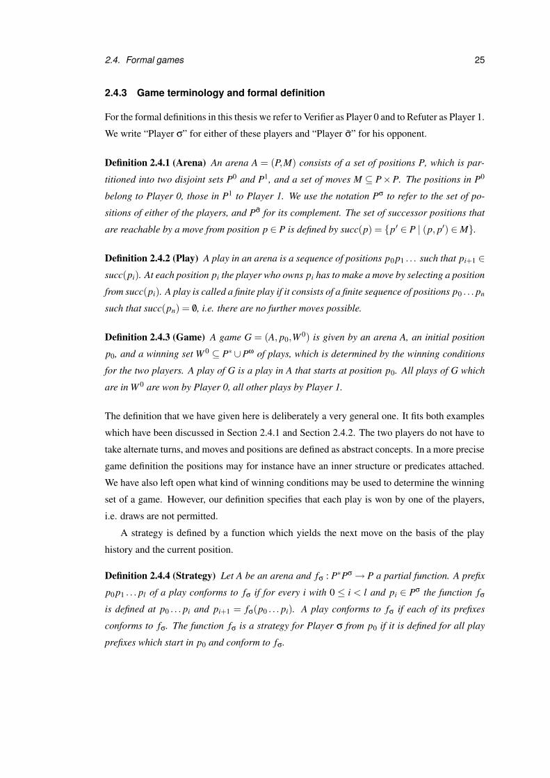
2.4.3 Game terminology and formal definition . . . . . . . . . . . . . . . . . 25
2.4.4 Computation of winning strategies . . . . . . . . . . . . . . . . . . . . 26
2.5 UML Tools . . . . . . . . . . . . . . . . . . . . . . . . . . . . . . . . . . . . 28
2.5.1 Modelling tools . . . . . . . . . . . . . . . . . . . . . . . . . . . . . . 28
2.5.2 Model checking and evaluation tools . . . . . . . . . . . . . . . . . . . 30
2.6 Related work . . . . . . . . . . . . . . . . . . . . . . . . . . . . . . . . . . . 33
vii
3 Games for UML software design 39
3.1 Why games with UML? . . . . . . . . . . . . . . . . . . . . . . . . . . . . . . 39
3.2 Exploration games . . . . . . . . . . . . . . . . . . . . . . . . . . . . . . . . 42
3.2.1 Example of an exploration game . . . . . . . . . . . . . . . . . . . . . 44
3.2.2 Plays without exploration . . . . . . . . . . . . . . . . . . . . . . . . 48
3.2.3 Plays with exploration . . . . . . . . . . . . . . . . . . . . . . . . . . 49
3.2.4 Significance of explorations . . . . . . . . . . . . . . . . . . . . . . . 51
3.3 Tool support for exploration games . . . . . . . . . . . . . . . . . . . . . . . . 52
4 Exploration game framework 55
4.1 Parameters and preconditions . . . . . . . . . . . . . . . . . . . . . . . . . . . 56
4.2 Move steps . . . . . . . . . . . . . . . . . . . . . . . . . . . . . . . . . . . . 57
4.3 Responsibility sets . . . . . . . . . . . . . . . . . . . . . . . . . . . . . . . . 60
4.4 Plays in strict mode . . . . . . . . . . . . . . . . . . . . . . . . . . . . . . . . 62
4.5 Plays in exploration mode . . . . . . . . . . . . . . . . . . . . . . . . . . . . 65
4.6 Computation of the arena and winning strategies . . . . . . . . . . . . . . . . . 70
5 Application to UML 77
5.1 General definitions and settings for all variants . . . . . . . . . . . . . . . . . . 78
5.1.1 All variants: Winning conditions . . . . . . . . . . . . . . . . . . . . . 78
5.1.2 All variants: Responsibilities . . . . . . . . . . . . . . . . . . . . . . . 80
5.1.3 All variants: Game settings . . . . . . . . . . . . . . . . . . . . . . . . 82
5.1.4 All variants: Explorer moves . . . . . . . . . . . . . . . . . . . . . . . 84
5.2 Property checking games . . . . . . . . . . . . . . . . . . . . . . . . . . . . . 85
5.2.1 Property checking games: Winning conditions . . . . . . . . . . . . . 85
5.2.2 Property checking games: Incrementations . . . . . . . . . . . . . . . 85
5.2.3 Variant A: State machines . . . . . . . . . . . . . . . . . . . . . . . . 86
5.2.4 Variant B: Activity diagrams . . . . . . . . . . . . . . . . . . . . . . . 111
5.2.5 Variant C: State machines and activity diagrams . . . . . . . . . . . . . 133
5.3 Extensions of property checking games . . . . . . . . . . . . . . . . . . . . . 143
5.3.1 Top-level activity diagrams . . . . . . . . . . . . . . . . . . . . . . . . 143
5.3.2 Sequence diagrams . . . . . . . . . . . . . . . . . . . . . . . . . . . . 143
5.3.3 Protocol state machines . . . . . . . . . . . . . . . . . . . . . . . . . . 146
5.4 Comparison games . . . . . . . . . . . . . . . . . . . . . . . . . . . . . . . . 153
viii

5.4.1 Comparison games: Winning conditions . . . . . . . . . . . . . . . . . 153
5.4.2 Variant D: Protocol realisability . . . . . . . . . . . . . . . . . . . . . 153
5.4.3 Variant E: Sequence realisability . . . . . . . . . . . . . . . . . . . . . 162
5.4.4 Variant F: State machine comparison . . . . . . . . . . . . . . . . . . 173
5.5 Conclusion . . . . . . . . . . . . . . . . . . . . . . . . . . . . . . . . . . . . 181
6 Prototype implementation 183
6.1 Functionality of the GUIDE tool . . . . . . . . . . . . . . . . . . . . . . . . . 183
6.1.1 Creation of the UML model . . . . . . . . . . . . . . . . . . . . . . . 183
6.1.2 Game setup . . . . . . . . . . . . . . . . . . . . . . . . . . . . . . . . 184
6.1.3 Playing a game . . . . . . . . . . . . . . . . . . . . . . . . . . . . . . 188
6.2 Tool specific game settings . . . . . . . . . . . . . . . . . . . . . . . . . . . . 191
6.3 Restrictions of the implementation . . . . . . . . . . . . . . . . . . . . . . . . 193
6.4 Used technologies . . . . . . . . . . . . . . . . . . . . . . . . . . . . . . . . . 194
6.5 GUIDE architecture . . . . . . . . . . . . . . . . . . . . . . . . . . . . . . . . 194
6.6 Extensions of GUIDE . . . . . . . . . . . . . . . . . . . . . . . . . . . . . . . 199
7 Discussion 201
7.1 General approach . . . . . . . . . . . . . . . . . . . . . . . . . . . . . . . . . 201
7.2 Exploration game framework . . . . . . . . . . . . . . . . . . . . . . . . . . . 203
7.3 Application to UML . . . . . . . . . . . . . . . . . . . . . . . . . . . . . . . 203
7.4 Prototype implementation . . . . . . . . . . . . . . . . . . . . . . . . . . . . . 205
8 Conclusion 207
Bibliography 211
ix

List of Figures
1.1 Game incrementation in “Calvinball” . . . . . . . . . . . . . . . . . . . . . . 5
2.1 Class diagram for a university registration system . . . . . . . . . . . . . . . . 9
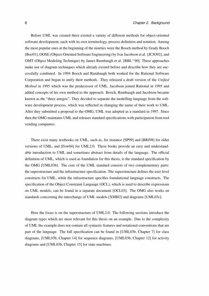
2.2 Sequence diagram modelling enrolment into a module . . . . . . . . . . . . . 10
2.3 Activity diagram for enrol . . . . . . . . . . . . . . . . . . . . . . . . . . . . . 12
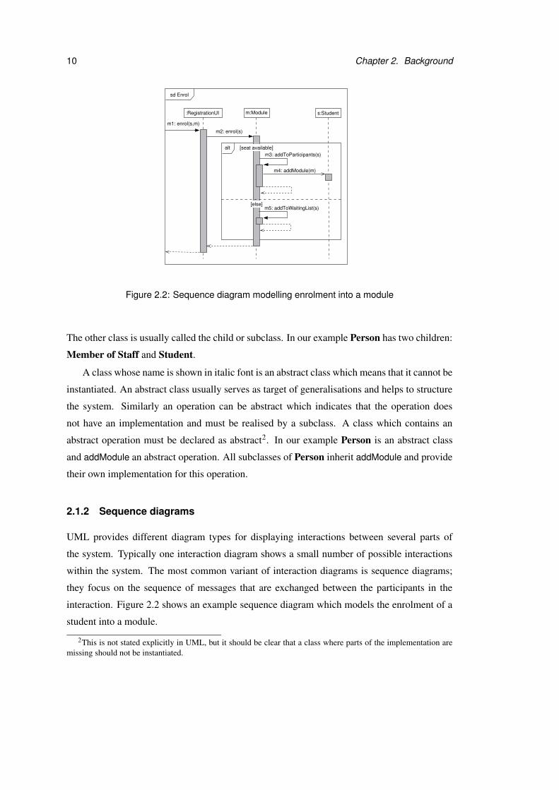
2.4 Activity diagram modelling online registration . . . . . . . . . . . . . . . . . . 13
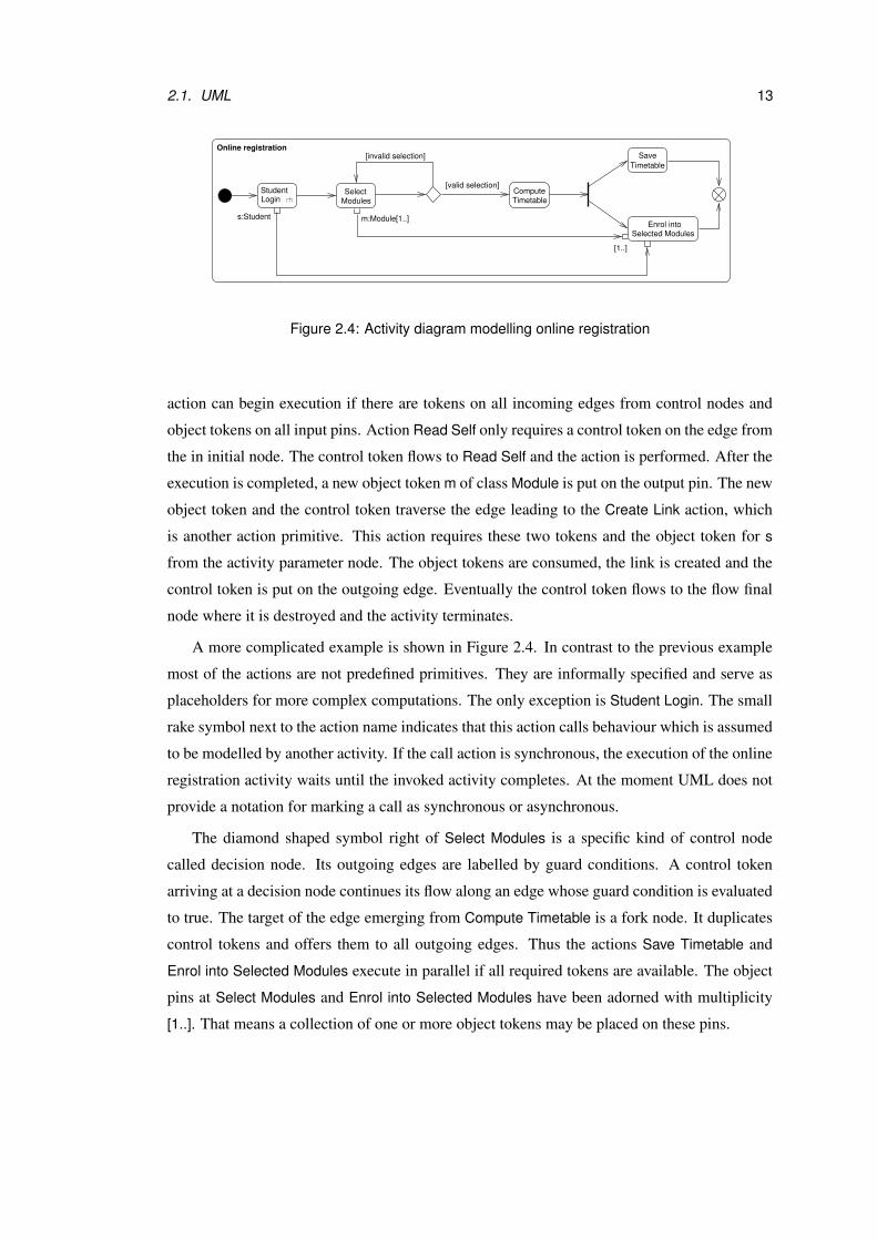
2.5 Behavioural state machine for Module . . . . . . . . . . . . . . . . . . . . . . 15
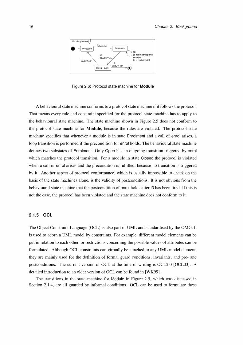
2.6 Protocol state machine for Module . . . . . . . . . . . . . . . . . . . . . . . . 16
2.7 Phases, iterations and workflows in RUP . . . . . . . . . . . . . . . . . . . . . 19
2.8 Example arena A1 . . . . . . . . . . . . . . . . . . . . . . . . . . . . . . . . . 23
2.9 Bisimulation game for two vending machines E and F . . . . . . . . . . . . . . 24
3.1 Repeated game incrementation . . . . . . . . . . . . . . . . . . . . . . . . . . 41
3.2 Example class diagram . . . . . . . . . . . . . . . . . . . . . . . . . . . . . . 44
3.3 State machines for Module and Student . . . . . . . . . . . . . . . . . . . . . 44
3.4 Positions and moves in the example game . . . . . . . . . . . . . . . . . . . . 46
3.5 State machine for Module after exploration . . . . . . . . . . . . . . . . . . . 50
4.1 Arena excerpt A2 . . . . . . . . . . . . . . . . . . . . . . . . . . . . . . . . . 58
4.2 Partition of A2 into move shapes . . . . . . . . . . . . . . . . . . . . . . . . . 59
4.3 Pseudocode for method nextMoves . . . . . . . . . . . . . . . . . . . . . . . . 71
4.4 Finite arena subgraph A3 . . . . . . . . . . . . . . . . . . . . . . . . . . . . . 72
4.5 Search graph for A3 . . . . . . . . . . . . . . . . . . . . . . . . . . . . . . . . 72
4.6 Pseudocode for computation of safe winning strategies – Part 1 . . . . . . . . . 73
4.7 Pseudocode for computation of safe winning strategies – Part 2 . . . . . . . . . 74
5.1 Hierarchy of exploration game variants . . . . . . . . . . . . . . . . . . . . . . 78
xi

5.2 Variant A: Example class diagram . . . . . . . . . . . . . . . . . . . . . . . . 87
5.3 Variant A: State machine for CS Student . . . . . . . . . . . . . . . . . . . . 88
5.4 Variant A: State machine for Employer . . . . . . . . . . . . . . . . . . . . . 89
5.5 Variant A: Initial position . . . . . . . . . . . . . . . . . . . . . . . . . . . . . 90
5.6 Variant A: Example move from Verifier’s position . . . . . . . . . . . . . . . . 94
5.7 Variant A: Firing a transition with an asynchronous invocation as effect . . . . 97
5.8 Variant A: Skipping a move and firing a transition with an empty trigger . . . . 99
5.9 Variant A: Firing a transition with a synchronous invocation as effect . . . . . . 107
5.10 Summary of variant A . . . . . . . . . . . . . . . . . . . . . . . . . . . . . . . 110
5.11 Variant B: Example class and instance diagram . . . . . . . . . . . . . . . . . 111
5.12 Variant B: Activity diagram modelling the operation of Controller . . . . . . . 112
5.13 Variant B: Activity diagram Compute Dose . . . . . . . . . . . . . . . . . . . 113
5.14 Variant B: Initial position . . . . . . . . . . . . . . . . . . . . . . . . . . . . . 114
5.15 Variant B: Example move from Refuter’s position . . . . . . . . . . . . . . . . 115
5.16 Variant B: Invocation of a parameterised activity . . . . . . . . . . . . . . . . . 117
5.17 Variant B: Execution of an informal action . . . . . . . . . . . . . . . . . . . . 118
5.18 Variant B: Execution of an asynchronous CallAction . . . . . . . . . . . . . . 120
5.19 Variant B: Execution of an AddStructuralFeatureValueAction . . . . . . . . . . 122
5.20 Variant B: Moving tokens over a JoinNode . . . . . . . . . . . . . . . . . . . . 122
5.21 Variant B: Moving tokens to an ActivityFinalNode . . . . . . . . . . . . . . . . 123
5.22 Variant B: Execution of a synchronous InvocationAction . . . . . . . . . . . . 129
5.23 Summary of variant B . . . . . . . . . . . . . . . . . . . . . . . . . . . . . . . 132
5.24 Variant C: Example class diagram . . . . . . . . . . . . . . . . . . . . . . . . 134
5.25 Variant C: State machine for CS Student . . . . . . . . . . . . . . . . . . . . 134
5.26 Variant C: State machine for Employer . . . . . . . . . . . . . . . . . . . . . 135
5.27 Variant C: Activity diagram for addEmployee . . . . . . . . . . . . . . . . . . 135
5.28 Variant C: Initial position . . . . . . . . . . . . . . . . . . . . . . . . . . . . . 136
5.29 Variant C: Asynchronous invocation of an activity by a state machine . . . . . . 137
5.30 Variant C: Event generation after synchronous invocation . . . . . . . . . . . . 140
5.31 Summary of variant C . . . . . . . . . . . . . . . . . . . . . . . . . . . . . . . 142
5.32 Variant extensions: Example sequence diagrams . . . . . . . . . . . . . . . . . 144
5.33 Variant extensions: Example moves in an extension by sequence diagrams . . . 147
5.34 Variant extensions: Protocol state machine for CS Student . . . . . . . . . . . 149
xii

5.35 Variant extensions: Example moves in an extension by protocol state machines 149
5.36 Variant extensions: Protocol state machine for Employer . . . . . . . . . . . . 151
5.37 Variant extensions: Protocol violation . . . . . . . . . . . . . . . . . . . . . . 152
5.38 Variant D: State machine for CS Student . . . . . . . . . . . . . . . . . . . . 154
5.39 Variant D: Protocol state machine for CS Student . . . . . . . . . . . . . . . . 155
5.40 Variant D: Initial position . . . . . . . . . . . . . . . . . . . . . . . . . . . . . 155
5.41 Variant D: Example moves . . . . . . . . . . . . . . . . . . . . . . . . . . . . 156
5.42 Summary of variant D . . . . . . . . . . . . . . . . . . . . . . . . . . . . . . . 161
5.43 Variant E: Example sequence diagrams . . . . . . . . . . . . . . . . . . . . . . 163
5.44 Variant E: State machine for CS Student . . . . . . . . . . . . . . . . . . . . 163
5.45 Variant E: State machine for Employer . . . . . . . . . . . . . . . . . . . . . 164
5.46 Variant E: Initial position . . . . . . . . . . . . . . . . . . . . . . . . . . . . . 164
5.47 Variant E: Example moves from Refuters’ positions . . . . . . . . . . . . . . . 166
5.48 Variant E: Example move from Verifier’s position . . . . . . . . . . . . . . . . 168
5.49 Summary of variant E . . . . . . . . . . . . . . . . . . . . . . . . . . . . . . . 172
5.50 Variant F: First version of state machine for CS Student . . . . . . . . . . . . 174
5.51 Variant F: Second version of state machine for CS Student . . . . . . . . . . . 175
5.52 Variant F: Initial position . . . . . . . . . . . . . . . . . . . . . . . . . . . . . 175
5.53 Variant F: Example moves from Refuter’s position . . . . . . . . . . . . . . . . 176
5.54 Variant F: Example move from Verifier’s position . . . . . . . . . . . . . . . . 178
5.55 Summary of variant F . . . . . . . . . . . . . . . . . . . . . . . . . . . . . . . 180
6.1 State machines for Module and Student . . . . . . . . . . . . . . . . . . . . . 184
6.2 GUIDE main window . . . . . . . . . . . . . . . . . . . . . . . . . . . . . . . 185
6.3 Dialogues for editing an expression . . . . . . . . . . . . . . . . . . . . . . . 186
6.4 General settings tab and context menu . . . . . . . . . . . . . . . . . . . . . . 187
6.5 Preparation of a play . . . . . . . . . . . . . . . . . . . . . . . . . . . . . . . 188
6.6 GUIDE play window showing a play without exploration . . . . . . . . . . . . 189
6.7 Dialogues for move steps . . . . . . . . . . . . . . . . . . . . . . . . . . . . . 189
6.8 GUIDE play window showing a play with exploration . . . . . . . . . . . . . . 190
6.9 The package structure of GUIDE . . . . . . . . . . . . . . . . . . . . . . . . . 195
6.10 GUIDE game framework – Game structure . . . . . . . . . . . . . . . . . . . 196
6.11 GUIDE game framework - Playing a game . . . . . . . . . . . . . . . . . . . . 196
6.12 GUIDE expression framework . . . . . . . . . . . . . . . . . . . . . . . . . . 197
xiii
6.13 GUIDE algorithm framework . . . . . . . . . . . . . . . . . . . . . . . . . . . 199
8.1 The fun of playing “Calvinball” . . . . . . . . . . . . . . . . . . . . . . . . . 209
xiv
List of Tables
2.1 Properties of UML modelling tools . . . . . . . . . . . . . . . . . . . . . . . . 31
5.1 All variants: Example assignment of responsibilities . . . . . . . . . . . . . . 81
5.2 Variant A: Example assignment of responsibilities . . . . . . . . . . . . . . . . 102
5.3 Variant B: Example assignment of responsibilities . . . . . . . . . . . . . . . . 127
5.4 Variant D: Example assignment of responsibilities . . . . . . . . . . . . . . . . 159
5.5 Variant F: Example assignment of responsibilities . . . . . . . . . . . . . . . . 180
xv

Chapter 1
Introduction
Most of the software development processes that are used today share two common principles:
they are iterative and incremental. An iteration concentrates on a specific part of the system and
involves the execution of all phases that belong to the development process for this part. During
the different phases of each iteration the system and the artifacts related to it are incremented.
In the design phase of each iteration the software designer will try to increment the design
of the system such that it fulfils the requirements which are relevant for the iteration. At this
stage the requirements are frequently discovered to be incomplete or inconsistent, and need to
be modified as well. The maintenance of requirements and design such that they fit with each
other is an essential part of all iterations in the software development process.
Usually there are different design solutions for a system, each of which has particular
strengths and weaknesses. Hence finding a design which meets the requirements is not enough.
The task of the software designer is to select a design which is a “good choice” for the system
under consideration. This requires an understanding of the system, the different design options
and their consequences.
A widely-used language for modelling the design of object-oriented software systems is
the Unified Modeling Language (UML). UML consists of several diagram types providing dif-
ferent views of the design. A design in UML is often informally defined and only covers those
parts of the system which are interesting enough to be modelled. Because of the popularity
of UML there exists a broad range of tools which assist the modeller in drawing the different
UML diagrams. However, none of these tools provides support for the actual design of the sys-
tem. So far there is no UML tool which helps the designer to check whether the design meets
the requirements, to experiment with incrementations of both parts, or to compare different
1
2 Chapter 1. Introduction
design options, although these tasks are very important for successful incremental software
development. The purpose of this thesis is to provide a foundation for UML tools which have
these capabilities and let the user explore the design by playing games.
As formal basis for this work exploration games are introduced. An exploration game
involves four participants: two players called Verifier and Refuter who compete with each
other, a Referee, and an Explorer. The game incorporates the design model of the system
and a specification of what it means for the design to be correct. The objective of Verifier
is to show that the design fits with the specification, while Refuter tries to find a flaw in the
design. All moves in the game are performed in several stages. The responsibility for each
stage can be assigned to one of the players or to the Referee. The responsibility assignments
allow the game participants to resolve non-determinacy during a play, which may be caused by
incompleteness or informality of the design model. The Explorer has the power to increment
the game definition at any point during a play. The incrementations can affect both the design
and the specification of the system and may improve the chances of winning for one of the
players.
The theoretical concepts that are presented in this thesis have been implemented in a pro-
totypical tool called GUIDE (Games with UML for Interactive Design Exploration). This tool
does not expect the designer to have any knowledge of formal games or verification and pro-
vides support for setting up a game on the basis of a UML design model. Once all necessary
parts of the game are defined the modeller can start a play. Thereby the role of the Explorer
always has to be played by the human designer, who may play any number of the other game
participants in addition. Taking on the role of Verifier or Refuter provides the modeller with a
specific perspective and goal for the design exploration. As Refuter he will concentrate on de-
tecting flaws in the design, as Verifier he will attempt to demonstrate that the design is correct.
GUIDE makes the moves for all game participants that are not played by the designer,
evaluates the winning conditions and guides the modeller through a play. If desired, the tool
attempts to compute a winning strategy for one of the players and uses it for making some of
the moves. After the user has incremented the game as Explorer or resolved non-determinacy in
the role of one of the other game participants, GUIDE may have to adapt the winning strategies
which it follows.
By repeatedly playing an exploration game and adding more detail to it the modeller refines
the design and its specification. At some point he may feel that both parts are stable and precise
enough for his purpose. The modeller does not further increment the game and concentrates

1.1. Contributions 3
on verifying the design. In the context of games this amounts to computing a winning strategy
for Verifier, which can be attempted by the GUIDE tool.
The exploration game framework can be applied to UML in many different variants. A
game variant has to specify how exactly the exploration game is defined, i.e. what its positions,
moves and winning conditions look like, which parts of the UML model are used for the defini-
tion, how the responsibilities of the players are assigned and how the Explorer may increment
the game. Concrete variants of exploration games can either be used to check if a design fulfils
a set of properties, or whether the UML diagrams that constitute the design are related to each
other in a particular way. Examples for both kinds of game variants are included in this thesis.
1.1 Contributions
This thesis contains three main contributions. First, the general framework of exploration
games is developed and defines a precise foundation for the implementation of UML tools with
the desired functionality. One of the differences to two-player games as known in verification
is that exploration games permit incrementations of the game definition while the game is be-
ing played. Furthermore exploration games contain responsibility assignments which allow the
players to resolve uncertain situations.
Second, the exploration game framework is applied to UML in different variants. This
demonstrates the usage and flexibility of the exploration game framework. The application to
UML also illustrates how the diagram types that are part of UML may be used in a comple-
mentary way such that they provide different views of the system and serve as a suitable basis
for an exploration game definition.
Third, the prototype tool GUIDE proves that the concepts developed in this thesis can be
put into practice. One of the example game variants that is introduced in this thesis can be
played by the user. GUIDE supports the designer in defining and playing the game, takes on
different roles in the play, and is able to compute winning strategies for the players. The tool
contains a direct implementation of the exploration game framework which can be instantiated
to create new game variants. GUIDE may also be extended by alternative algorithms for the
computation of winning strategies and additional expression types for the definition of winning
strategies and responsibilities.
Note that experimental evaluation of exploration games for UML software design is not in
the scope of thesis. Using the GUIDE tool for experiments with test users and evaluating their

4 Chapter 1. Introduction
feedback is one of the most important points for future work and will be discussed further in
Chapter 8.
1.2 Thesis outline
In the remainder of this chapter we introduce some notational conventions for this thesis. Chap-
ter 2 gives an overview on software design with UML and formal games. The general approach
of applying games to UML software design is motivated and explained informally on an ex-
ample in Chapter 3. The formal exploration game framework is defined in Chapter 4. The
emphasis of this thesis is on the application of the framework to UML in different variants,
which is presented in Chapter 5. Chapter 6 explains how exploration games have been imple-
mented in our prototype tool GUIDE. In Chapter 7 we discuss some of the concepts which
have been presented in this thesis, their implementation and alternatives to the chosen solution.
Chapter 8 summarises the contributions of this thesis and points out possibilities for future
work.
Chapter 4 contains mathematical definitions and requires some understanding of formal
methods and notation. For Chapter 5 we assume that the reader is familiar with UML, in
particular with UML activity diagrams and state machines as defined in the UML 2.0 standard
[UML03b].
1.3 Notation
The following conventions are used throughout this thesis:
• Class names always start with a capital letter and are shown in bold face, like Class.
• Names of objects, positions, moves, and other elements of concrete UML models or
games are shown in sans serif font, like object.
• Whenever we refer to one of the players we use the female form for Verifier and the male
form for Refuter.
Additional notational concepts for particular chapters are explained when they are needed.
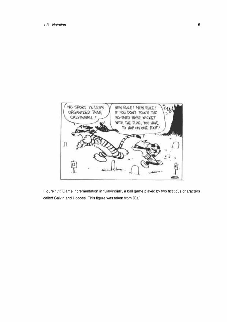
1.3. Notation 5
Figure 1.1: Game incrementation in “Calvinball”, a ball game played by two fictitious characters
called Calvin and Hobbes. This figure was taken from [Cal].


Chapter 2
Background
Modelling with UML and formal games for verification are broad research areas which are not
strongly connected with each other. This chapter provides a brief introduction to both topics.
Modelling with UML is explained on an example model which is used in different variations
later in this thesis. Games are also first introduced informally using two examples. After that
we give a formal definition of games and discuss an algorithm for the computation of winning
strategies.
Since the purpose of this thesis is to extend the capabilities of UML design tools, we pro-
vide an overview on the current state of tool support for UML. The emphasis is on investigating
how far tools assist the designer in the process of defining a suitable and correct UML model.
Finally a selection of related work is discussed. We consider formal approaches to UML, in
particular those which are related to tool support, and interactive techniques for software de-
sign in general. Furthermore we look at applications of formal games with a focus on problems
in computer science.
2.1 UML
The Unified Modeling Language (UML) is a standard notation which is maintained by the
Object Management Group (OMG). UML is a complex language which is aimed at general ap-
plicability. Among the core areas where UML is used are business process modelling, software
and hardware development. UML consists of various diagram types, a constraint language and
an action framework. Each diagram type provides a specific view on the system and can be
used on different levels of abstractions. The current UML version at the time of writing is
UML2.0.
7
8 Chapter 2. Background
Before UML was created there existed a variety of different methods for object-oriented
software development, each with its own terminology, process definition and notation. Among
the most popular ones at the beginning of the nineties were the Booch method by Grady Booch
[Boo91], OOSE (Object-Oriented Software Engineering) by Ivar Jacobson et al. [JCJO92], and
OMT (Object Modeling Technique) by James Rumbaugh et al. [RBL+90]. These approaches
make use of diagram techniques which already existed before and describe how they are suc-
cessfully combined. In 1994 Booch and Rumbaugh both worked for the Rational Software
Corporation and began to unify their methods. They released a draft version of the Unified
Method in 1995 which was the predecessor of UML. Jacobson joined Rational in 1995 and
added concepts of his own method to the approach. Booch, Rumbaugh and Jacobson became
known as the “three amigos”. They decided to separate the modelling language from the soft-
ware development process, which was reflected in changing the name of their work to UML.
After they submitted a proposal to the OMG, UML was adopted as a standard in 1997. Since
then the OMG maintains UML and releases standard specifications with participation from tool
vending companies.
There exist many textbooks on UML, such as, for instance [SP99] and [BRJ98] for older
versions of UML, and [Fow04] for UML2.0. These books provide an easy and understand-
able introduction to UML and sometimes abstract from details of the language. The official
definition of UML, which is used as foundation for this thesis, is the standard specification by
the OMG [UML03b]. The core of the UML standard consists of two complementary parts:
the superstructure and the infrastructure specification. The superstructure defines the user level
constructs for UML, while the infrastructure specifies foundational language constructs. The
specification of the Object Constraint Language (OCL), which is used to describe expressions
on UML models, can be found in a separate document [OCL03]. The OMG also works on
standards concerning the interchange of UML models [XMI02] and diagrams [UML03c].
Here the focus is on the superstructure of UML2.0. The following sections introduce the
diagram types which are most relevant for this thesis on an example. Due to the complexity
of UML the example does not contain all syntactic features and notational conventions that are
part of the language. The full specification can be found in [UML03b, Chapter 7] for class
diagrams, [UML03b, Chapter 14] for sequence diagrams, [UML03b, Chapter 12] for activity
diagrams and [UML03b, Chapter 15] for state machines.

2.1. UML 9
Member of Staff
staffNo: Integer
0..*
name: Stringaddress: String
changeAddress(a:String)
Person
matNo: Integer
addModule(m:Module)
lecturers
matriculate()
completePractical()
0..*
0..*
0..*
Module
maxParticipants: Integer
enrol(s:Student)addToWaitingList(s:Student)addToParticipants(s:Student)
name: StringminParticipants: Integer
assign(mos:Member of Staff)
waitingFor
taughtModules
modulesparticipants
0..*
waitingList {ordered}
0..*
RegistrationUI
displayModules(s:Student)enrol(s:Student,m:Module)
login()
Student
Figure 2.1: Class diagram for a university registration system
2.1.1 Class diagrams
UML class diagrams are used to model the static structure of an object-oriented system. Fig-
ure 2.1 shows an excerpt of a class diagram for a university registration system. The diagram
consists of five classes which are represented by rectangles. A class can contain attributes and
operations, together with information about their types and parameters. Class Person has two
attributes called name and address. The specified operations for Person are changeAddress
and addModule.
Classes can be related to each other by associations or generalisations. The line between
Member of Staff and Module indicates that these two classes are associated. This association
is navigable in both directions, which means objects of each class have access to a collection of
objects of the other class. An association which is only navigable in one direction is drawn as
an arrow, indicating the navigability1. An association end can be adorned by a role name and
a multiplicity. In our example the association end at Module has the role name taughtModules
and multiplicity 0..*. If read in the direction from Member of Staff to Module, the association
models that each member of staff teaches arbitrarily many modules. These modules are re-
ferred to as the member of staff’s taughtModules. Generalisation relationships are represented
by arrows with a hollow triangle as an arrowhead and are used to model inheritance. The ar-
rowhead points to the more general class, which is the parent or superclass in the relationship.
1In fact, the notation that we use here is the last one of three options that are mentioned in the UML standard[UML03b, p.83]. The disadvantage is that an association with two-way navigability cannot be distinguished fromassociations where no navigation is possible at all. However, we do not consider non-navigable associations here,and thus the notation is unambiguous.
10 Chapter 2. Background
��������������������
��������������������
������������������������������������������������������������������������������������������
alt
[else]
[seat available]
m1: enrol(s,m)
m3: addToParticipants(s)
m4: addModule(m)
m5: addToWaitingList(s)
:RegistrationUI m:Module s:Student
m2: enrol(s)
sd Enrol
Figure 2.2: Sequence diagram modelling enrolment into a module
The other class is usually called the child or subclass. In our example Person has two children:
Member of Staff and Student.
A class whose name is shown in italic font is an abstract class which means that it cannot be
instantiated. An abstract class usually serves as target of generalisations and helps to structure
the system. Similarly an operation can be abstract which indicates that the operation does
not have an implementation and must be realised by a subclass. A class which contains an
abstract operation must be declared as abstract2. In our example Person is an abstract class
and addModule an abstract operation. All subclasses of Person inherit addModule and provide
their own implementation for this operation.
2.1.2 Sequence diagrams
UML provides different diagram types for displaying interactions between several parts of
the system. Typically one interaction diagram shows a small number of possible interactions
within the system. The most common variant of interaction diagrams is sequence diagrams;
they focus on the sequence of messages that are exchanged between the participants in the
interaction. Figure 2.2 shows an example sequence diagram which models the enrolment of a
student into a module.
2This is not stated explicitly in UML, but it should be clear that a class where parts of the implementation aremissing should not be instantiated.

2.1. UML 11
The three rectangles on top together with the dashed vertical lines that emerge from them
are called lifelines. Each rectangle represents a participant in the interaction. In the example an
anonymous object of class RegistrationUI, a Module object m and a Student object s interact
with each other. The arrows between the lifelines represent messages and are labelled by m1,
m2, etc. The type of a message is indicated by the kind of arrow that is used to model it. A
synchronous message is represented by a solid arrow with filled arrow head like message m2.
Reply messages are shown as dashed arrows and always correspond to a synchronous message
which has been sent earlier. For example, the message from m back to the RegistrationUI
object is the reply message for m2. Message m4 is an example of an asynchronous message
and is represented by a solid arrow with an open arrow head. The advantage of modelling m4
as an asynchronous message is that object m can continue its computation of addToParticipants
directly after sending m4. If m4 was a synchronous message, m would have to wait for a reply
from s.
The ends of a message arrow represent event occurrences. The tail end stands for the event
of sending the message, the head end for receiving the message. The grey rectangles on the
lifelines are called execution occurrences. They model behaviour that takes place between two
event occurrences, typically between the receipt of a message and sending a return message.
Execution occurrences can be nested like the ones on the lifeline for m.
The fragment labelled by alt is used to express choice of behaviour. Within the fragment
a dashed line separates two alternative behaviours which are labelled by guard conditions. At
most one of those parts whose guard condition is evaluated to true executes during an inter-
action. In the example exactly one of the guard conditions holds when the interaction takes
place: if there is a seat available, student s is enrolled into module m; otherwise s is added to
the waiting list for m.
2.1.3 Activity diagrams
The foundation for specification of behaviour in UML is the action framework. The standard
specification defines various action primitives in [UML03b, Chapter 11]. Actions can be used
to manipulate the system state, perform computations, invoke behaviour and communicate with
other parts of the system. They are always executed within an activity which provides the con-
text of the execution and are often used informally. The general notation for actions in UML
is to show the name of the action or a description of it in a round-cornered rectangle. Alter-
natively a purely textual notation may be used. UML leaves the concrete implementation of

12 Chapter 2. Background
ReadSelf
m:Module
Create Linkparticipant−module
Enrol s:Student
s
Figure 2.3: Activity diagram for enrol
the action primitives and most of the representation issues open to “surface action languages”,
such as, for example the Action Specification Language (ASL) [ASL01] or parts of the Spec-
ification and Description Language (SDL) [SDL]. The UML specification version 1.5 where
the action semantics was first introduced contains some examples of mappings from existing
action languages to UML [UML03a, Appendix B].
An activity coordinates the execution of actions. The emphasis is on the conditions for
execution and the order in which actions are performed. It is irrelevant which kind of object
performs an action and what object state changes are caused by it. State machines, which
are discussed in Section 2.1.4, put a focus on modelling these aspects. An activity consists of
nodes which are connected by edges. Each node of an activity is either an action, object node or
control node. Object and control nodes are used to model control and data flow and are marked
by tokens. The execution of an activity is based on token flow, rather as in coloured Petri
Nets [Jen97], [ERRW03]. Figure 2.3 shows an activity which represents an implementation of
operation enrol in class Module.
UML provides many different notations for object nodes. The one which is used here
shows object nodes as pins attached to actions. A pin is notated by a small rectangle such as
the output pin on the right hand side of action Read Self, which is a UML action primitive.
The example diagram contains two control nodes: an initial node shown as solid circle and a
flow final node represented by symbol ⊗. The label at the top of the diagram indicates that
the activity requires a parameter s of type Student, which corresponds to the signature of the
operation whose implementation is modelled by the activity. Object nodes for activity inputs
and outputs are called activity parameter nodes. They are shown as rectangles on the edge of
the diagram. The activity parameter node in the example diagram is labelled by s.
When our example activity is invoked, an object token representing parameter s is put on
the activity parameter node. Notice that the term object token is used both for objects and data
in UML. Furthermore a control token is put on the edge emerging from the initial node. An
2.1. UML 13
m:Module[1..]s:Student
ModulesSelect
LoginStudent
[valid selection]
SaveTimetable
Enrol into
[1..]
[invalid selection]
Selected Modules
TimetableCompute
Online registration
Figure 2.4: Activity diagram modelling online registration
action can begin execution if there are tokens on all incoming edges from control nodes and
object tokens on all input pins. Action Read Self only requires a control token on the edge from
the in initial node. The control token flows to Read Self and the action is performed. After the
execution is completed, a new object token m of class Module is put on the output pin. The new
object token and the control token traverse the edge leading to the Create Link action, which
is another action primitive. This action requires these two tokens and the object token for s
from the activity parameter node. The object tokens are consumed, the link is created and the
control token is put on the outgoing edge. Eventually the control token flows to the flow final
node where it is destroyed and the activity terminates.
A more complicated example is shown in Figure 2.4. In contrast to the previous example
most of the actions are not predefined primitives. They are informally specified and serve as
placeholders for more complex computations. The only exception is Student Login. The small
rake symbol next to the action name indicates that this action calls behaviour which is assumed
to be modelled by another activity. If the call action is synchronous, the execution of the online
registration activity waits until the invoked activity completes. At the moment UML does not
provide a notation for marking a call as synchronous or asynchronous.
The diamond shaped symbol right of Select Modules is a specific kind of control node
called decision node. Its outgoing edges are labelled by guard conditions. A control token
arriving at a decision node continues its flow along an edge whose guard condition is evaluated
to true. The target of the edge emerging from Compute Timetable is a fork node. It duplicates
control tokens and offers them to all outgoing edges. Thus the actions Save Timetable and
Enrol into Selected Modules execute in parallel if all required tokens are available. The object
pins at Select Modules and Enrol into Selected Modules have been adorned with multiplicity
[1..]. That means a collection of one or more object tokens may be placed on these pins.

14 Chapter 2. Background
Activity diagrams have undergone severe changes during the transition to UML2.0 and
there are still various open issues that have to be addressed. Further details and comments
about the current state of UML2.0 actions and activities can be found in a series of articles in
[Boc03a], [Boc03b], [Boc03c], [Boc04].
2.1.4 State machines
A UML state machine specifies the internal behaviour of a model element. Here we assume
that a state machine is defined for a class, which is the most common case of usage. UML
provides two different kinds of state machines called behavioural state machines and protocol
state machines. Both kinds of state machines consist of states and transitions. In order to allow
easy reference to the transitions in the example diagrams they have been named by t1, t2, etc.
We first consider behavioural state machines on the example for class Module which is
shown in Figure 2.5. Each transition label is of the form trigger[guard]/effect. The trigger3 of
a transition is an event, such as the call of an operation or reception of a signal, and may fire the
transition. In this thesis the names of triggers which represent the reception of a signal start with
a capital letter. If an event arrives at an object whose behaviour is specified by the state machine,
it is put into the object’s event pool. The events in the pool are dispatched and processed one
by one by the state machine. The UML specification leaves it open in which order the events
are dispatched. The guard constraint specifies under which condition the transition is fired. A
transition is enabled if the event which is currently processed satisfies its trigger and its guard
is evaluated to true when the event is dispatched. If an event enables more than one transition
in the same state machine, one of them is fired. The effect of a transition refers to an activity
(see Section 2.1.3) which is executed when the transition is fired. For example, the triggers
at transitions t5 and t6 are satisfied if the event EndOfYear is dispatched. If guard condition
module successful is evaluated to true, t6 fires and its effect Update Description is executed.
Notice that all components of a transition label are optional. Transition t2, for instance, is only
labelled by a guard condition.
Activities can not only be attached to transitions, but also to states. It is possible to specify
which activities are performed upon entry to or exit from a state. For example, Arrange Student
Groups is an entry activity of state Being Taught. An ongoing activity which is performed as
long as the object is in the state or until its execution is completed, is identified by the keyword
do, such as for Mark Practicals in Figure 2.5.3In fact a transition can have an arbitrary number of triggers [UML03b, p.498]. For simplicity we only consider
transitions with at most one trigger.
2.1. UML 15
Closed
��������
Proposed
[module successful]/
t1:
t4:
t5:
t6:
t2:
Open [waiting list full]
Being Taught
Module
[else]
Enrolment
Scheduled/Update Webpage
EndOfYear
Update Description
entry / Arrange Student Groups
do / Mark Practicals
enrol(s)t3:
StartOfYear
EndOfYear
Figure 2.5: Behavioural state machine for Module
State machines in UML are hierarchical. A state may be a composite state which contains
other states and transitions. An example for a composite state is Enrolment, which contains the
simple states Open and Closed and transitions t2 and t3. If a module is in state Open it is also
in state Enrolment. In general a composite state can be orthogonal, i.e. it can contain two or
more regions. That means an object can be in two or more states at the same hierarchy level in
the state machine. Hence a state configuration of a state machine is defined as a set of trees of
states [UML03b, p.481] in UML. An example of a state machine with orthogonal regions will
be considered in Section 5.2.3.
The initial state of a state machine is represented by a small solid filled circle. It is the
source of a transition leading to the default state of the state machine. The default state of the
state machine for Module is Proposed. A final state is the target of a transition and models the
termination of the state machine and its context object. It is shown as a circle surrounding a
solid filled circle, like the target of transition t5.
Protocol state machines express usage protocols for a classifier and their notation is very
similar to the one for behavioural state machines. An example for class Module is shown in
Figure 2.6. Transitions in protocol state machines are only used to specify how the state of an
object changes on the occurrence of an event and do not invoke activities. Often the events at
transitions are call events, but it is not forbidden to use other events as well.
UML permits to show parts of the pre- and postconditions of operations in the labels of
protocol transitions which are of the form [pre]trigger/[post]. In the protocol state machine
for Module this notation has been used at transition t8. Alternatively pre- and postconditions
of an operation can be defined by separate constraints (see Section 2.1.5).
16 Chapter 2. Background
Being Taught
Enrolment
������������
Proposed
t7:
t9:
t10:
t11:[s in participants]enrol(s)
t8:[s not in participants]
Module {protocol}
Scheduled
EndOfYearStartOfYear
EndOfYear
Figure 2.6: Protocol state machine for Module
A behavioural state machine conforms to a protocol state machine if it follows the protocol.
That means every rule and constraint specified for the protocol state machine has to apply to
the behavioural state machine. The state machine shown in Figure 2.5 does not conform to
the protocol state machine for Module, because the rules are violated. The protocol state
machine specifies that whenever a module is in state Enrolment and a call of enrol arises, a
loop transition is performed if the precondition for enrol holds. The behavioural state machine
defines two substates of Enrolment. Only Open has an outgoing transition triggered by enrol
which matches the protocol transition. For a module in state Closed the protocol is violated
when a call of enrol arises and the precondition is fulfilled, because no transition is triggered
by it. Another aspect of protocol conformance, which is usually impossible to check on the
basis of the state machines alone, is the validity of postconditions. It is not obvious from the
behavioural state machine that the postcondition of enrol holds after t3 has been fired. If this is
not the case, the protocol has been violated and the state machine does not conform to it.
2.1.5 OCL
The Object Constraint Language (OCL) is also part of UML and standardised by the OMG. It
is used to adorn a UML model by constraints. For example, different model elements can be
put in relation to each other, or restrictions concerning the possible values of attributes can be
formulated. Although OCL constraints can virtually be attached to any UML model element,
they are mainly used for the definition of formal guard conditions, invariants, and pre- and
postconditions. The current version of OCL at the time of writing is OCL2.0 [OCL03]. A
detailed introduction to an older version of OCL can be found in [WK99].
The transitions in the state machine for Module in Figure 2.5, which was discussed inSection 2.1.4, are all guarded by informal conditions. OCL can be used to formulate these

2.2. Software development processes 17
conditions more precisely. For example, instead of the informal condition waiting list full at t2the following constraint could be used:
self.waitingList.size()>=15
This expression specifies clearly that the waiting list is regarded as full if it contains at least 15
students. The identifier self refers to a Module object, and the role name waitingList, which also
appears in the class diagram in Figure 2.1, is used to access the module’s collection of students
on the waiting list.Below we give examples of two class invariants for Module and pre- and postconditions
for operation enrol in OCL.
context Module
inv: self.participants->size()<=100
inv: self.oclInState(Being Taught) implies
self.participants->forall(p|p.oclInState(Studying))
context Module::enrol(s:Student)
pre: self.participants->excludes(s)
post: self.participants->includes(s)
The first invariant restricts the size of the collection participants of a Module object. The
second one relates a state from the state machine for Module to a state of Student, for which
no state machine diagram has been given yet. If a module is in state Being Taught, all its
participants have to be in state Studying. The precondition for enrol expresses that student s
who is to be enrolled into the module should not already be a participant, and the postcondition
ensures that s is a participant after the operation is completed. These constraints are formal
versions of the pre- and postconditions attached to transition t8 in the protocol state machine
shown in Figure 2.6.
The specification of invariants and pre- and postconditions are the most common ways of
using OCL. Often there is also a need to refer to temporal properties of UML model elements,
which is not possible with the current OCL version. Extensions of OCL, such as for instance
presented in [BFS02] and [FA03], have to be considered for this purpose.
2.2 Software development processes
Developing a large software system consists of many different activities such as clarifying the
requirements, modelling the design of the system, implementation and testing. Software de-
velopment processes offer guidance about how and when these activities should be performed.
18 Chapter 2. Background
A process definition is, for example, part of the object-oriented software development methods
whose notation was the basis for UML (see Section 2.1).
Today software development processes are normally regarded as independent of a particular
notation. However, UML is frequently used and recommended for some of the artifacts that are
produced during the process, such as the software design. Software development processes are
frameworks that do not aim for direct applicability but have to be customised for the concrete
needs of a software company or project. The most important point with respect to this thesis
is that all modern software development processes are iterative and incremental. These two
principles increase the flexibility to react to changes during the software development and
reduce the risk associated with it.
In this section we consider “The Rational Unified Process” (RUP) and “Extreme Program-
ming” (XP) as two examples of software development processes which are iterative and incre-
mental. RUP has been developed by the Rational Software company which is now owned by
IBM. A short introduction to the process is given in [Kru01] and an extensive explanation can
be found in [JBR99]. Originally RUP belonged to the class of heavyweight processes which
are used for large projects and require a lot of non-code artifacts to be produced. Meanwhile
RUP and its corresponding tool support have become more flexible and IBM claims that RUP
can be customised for any project. XP is introduced in [Bec99] and clearly belongs to the other
side of the spectrum. It is a lightweight or agile process, where code is the central artifact that
is created.
2.2.1 The Rational Unified Process
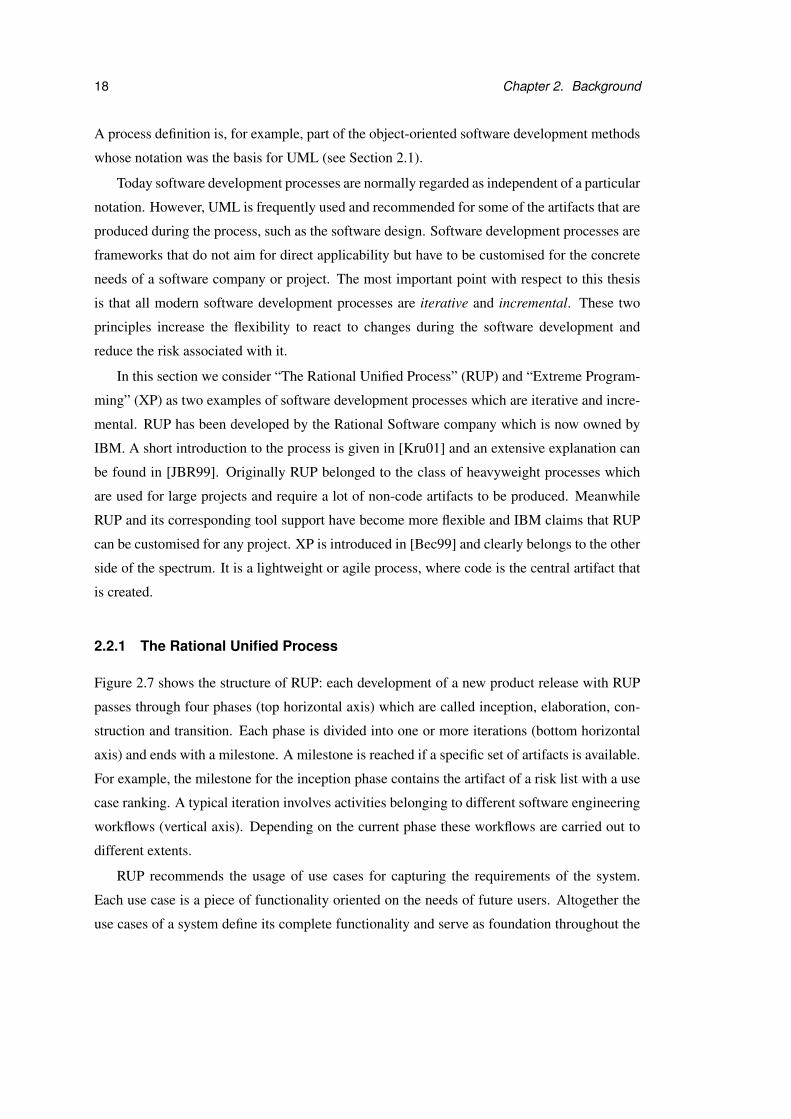
Figure 2.7 shows the structure of RUP: each development of a new product release with RUP
passes through four phases (top horizontal axis) which are called inception, elaboration, con-
struction and transition. Each phase is divided into one or more iterations (bottom horizontal
axis) and ends with a milestone. A milestone is reached if a specific set of artifacts is available.
For example, the milestone for the inception phase contains the artifact of a risk list with a use
case ranking. A typical iteration involves activities belonging to different software engineering
workflows (vertical axis). Depending on the current phase these workflows are carried out to
different extents.
RUP recommends the usage of use cases for capturing the requirements of the system.
Each use case is a piece of functionality oriented on the needs of future users. Altogether the
use cases of a system define its complete functionality and serve as foundation throughout the

2.2. Software development processes 19
Figure 2.7: Phases, iterations and workflows in RUP. This figure was taken from [Kru01].
development process. In each iteration a set of new use cases is added and the system grows
incrementally.
Additionally the architecture of the system plays an important role in RUP. It gives an ab-
stract view of the whole design and is determined iteratively. A first outline of the architecture
is given independently of the use cases. In later iterations the realisation of key use cases leads
to an extension and refinement of the architecture. On the other hand the architecture influences
the way in which use cases are implemented. The architecture gives the system its form while
the use cases determine its functionality. There is a strong connection between use cases and
architecture and they are developed in parallel.
2.2.2 Extreme Programming
The general idea of XP is to use well-known practices which have proven to be valuable in
software engineering to an extreme extent in parallel. Therefore it is not surprising that XP
contains some concepts that are also found in RUP, such as the description of the system func-
tionality in terms of use cases (“stories” in XP), iterative and incremental software development
and the definition of a stable architecture (“metaphor” in XP) at an early stage.
Moreover XP puts a strong emphasis on testing and implementation. Unit tests are written
by programmers, even before the corresponding implementation takes place, and an on-site

20 Chapter 2. Background
customer creates functionality tests. New code is integrated continuously and development
proceeds only if all tests that currently exist for the system are passed. These concepts allow
early production of a simple system and further development with small releases.
Programming in XP is done in pairs which change dynamically. One of the partners imple-
ments a specific method while the other one thinks about the general approach, simplifications,
and possible test cases that have not been considered yet. The code which is produced by a pair
can be changed by any member of the project. Pair programming and collective ownership are
supported by a coding standard which is adopted by the whole team.
Design and planning in XP concentrate on present problems and are updated only when it is
necessary. The system design is required to be as simple as possible for the current situation and
is restructured when unnecessary complexity is discovered. Changes in planning and design are
not feared, they are accepted as unavoidable and treated when they occur. Working overtime
continuously should not happen in an XP project and if it does, it is regarded as a sign that
there is something wrong with the planning.
Modelling in UML or any other graphic notation is often not part of an XP project. “Ex-
treme Modeling” [XM] applies principles of XP to modelling in order to combine these two
techniques. The basic idea is to create models which can be executed, tested and transformed
into code in regular intervals with the help of an integrated tool. Extreme Modeling was later
renamed to “Agile Modeling” [AM], mainly to reflect that the concepts suggested are not only
restricted to the scope of Extreme Programming but can also be applied to other processes.
2.3 Validation by reviews
Reviews are used to check the artifacts which have been produced during the software develop-
ment process. They are often applied to code, but also to design and test cases, with the aim of
identifying problems. In [Hum95] three different kinds of review methods are distinguished:
inspections, walkthroughs and personal reviews.
Inspections are the most formal of the three methods and have first been introduced by
Fagan in [Fag76]. Typically an inspection team consists of a moderator, the author of the ar-
tifact that is inspected, a scribe, and a group of inspectors, who are usually other designers,
programmers or testers. Sometimes a client representative is invited to participate in a review.
Before an artifact can be inspected, it has to meet some entry requirements. If code is reviewed
a common entry requirement is that it has to compile without errors and warnings. In the prepa-
ration phase of an inspection the members of the team familiarise themselves separately with

2.4. Formal games 21
the artifact that is reviewed and note questions. On the basis of this preparation the moderator
plans and schedules an inspection meeting.
During the meeting the artifact is presented by the author and discussed with the other team
members. The meeting is aimed at discovering problems, not on discussing possible solutions.
The moderator must ensure that all important issues that were planned for the meeting are
addressed. The scribe records the problems that are discovered together with their gravity,
which is estimated by the team. After the meeting the author receives a report with these
findings and starts to work on solutions to the problems which need fixing. For more detailed
explanations on inspections see for example [SP99] and [Som04].
Walkthroughs [You89] are a less formal variant of inspections. Often they concentrate on
particular usage scenarios of the system which are “walked through”. They do not require so
much advance preparation and follow-up changes. Walkthroughs help to resolve misunder-
standings between people working on different parts of the product or to discover omissions.
They are also frequently used for introducing new staff to the project.
In a personal review the author of an artifact examines his own work very closely. In
contrast to the other review techniques personal reviews are not a group activity and there is
no coordination between different team members required. A team review puts more pressure
on the author to deliver an artifact of high quality, because he knows that other people will
examine it closely. It is also often more difficult for the author of an artifact to discover his own
mistakes than for people without prior knowledge about it.
2.4 Formal games
Game theory has a long history in many different research areas [Wal01]. The first fundamental
and formal definition was given with respect to economics by von Neumann and Morgenstern
[vNM44]. Therein games are divided into two main categories: depending on whether the
players form coalitions or not a game is either cooperative or non-cooperative. Both cooper-
ative and non-cooperative games have been further classified and successfully applied to real
world problems over the last decades. They have been used as formal models for many differ-
ent kinds of interactions, such as, for example, bargaining and auctions in economics, voting
in politics and evolution in biology.
Non-cooperative games as used in formal verification of software systems are most rele-
vant in the context of this thesis. These games are based on a formal model of the system and
a specification of what it means for the model to be correct. The specification can be given in a

22 Chapter 2. Background
variety of ways. One possibility is to develop a process which is supposed to stand in some for-
mal relation to the system model; perhaps the two are supposed to be equivalent or perhaps one
is supposed to be a refinement of the other according to one of the many different equivalence
and refinement relations. Alternatively, the specification may be given as a logical formula in
a temporal logic such as Linear Temporal Logic (LTL), or by an acceptance condition from
automata theory.
The purpose of playing a game is to find out whether the system model fulfils the specifi-
cation. Games of this kind are played between two players called Verifier and Refuter. In this
thesis we use the female form to refer to Verifier, and the male form to refer to Refuter. The
aim of Verifier is to show that the model fulfils the specification while Refuter tries to prove
that this is not the case.
A game is played in an arena which is a directed graph with positions as vertices and
moves as edges. A play of a game starts at an initial position in the arena and is a sequence
of positions which respects the move relation. Each position in the game belongs to one of the
players. The player who owns the current position makes the next move in a play. Each player
wins a particular set of plays, which is identified by winning conditions.
A player can play the game according to a strategy, which is a set of rules. These rules
tell the player for each of his positions how to make the next move and may depend on earlier
decisions taken in the game. A strategy is called a winning strategy if a player wins every game
from the initial position in which he uses it. A winning strategy for Verifier can be viewed as a
proof that the property holds. Similarly, a winning strategy for Refuter yields counter-examples
which demonstrate that the property is violated under certain circumstances. Thus verification
by formal games involves computing a winning strategy for one of the players.
In the remainder of this section we consider two kinds of games that are used in verification
as examples. After that we give a formal definition of a game and discuss an example algo-
rithm for the computation of winning strategies. For a more detailed introduction to games in
verification see, for instance, [Tho02] and [GTW02].
2.4.1 Reachability games
Figure 2.8 shows an example arena A1 where Verifier’s positions are shown as white rectan-
gles with label V after the position name. Refuter’s positions are represented by grey-shaded
rectangles and labelled by R. The initial position for this example game is p0. We assume that
Verifier wins all plays during which a position in target set X = {p7,p8} is reached. Here we
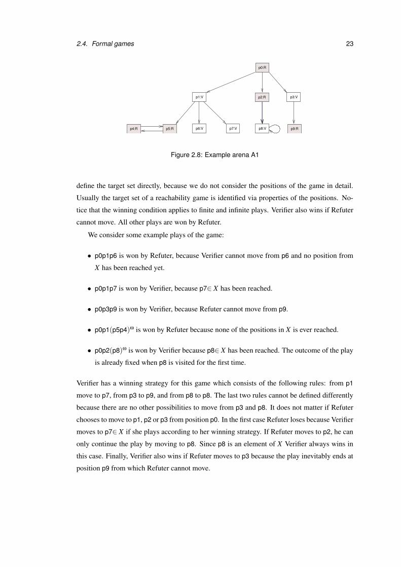
2.4. Formal games 23
p0:R
p2:R
p4:R p5:R p6:V p7:V p8:V
p3:Vp1:V
p9:R
Figure 2.8: Example arena A1
define the target set directly, because we do not consider the positions of the game in detail.
Usually the target set of a reachability game is identified via properties of the positions. No-
tice that the winning condition applies to finite and infinite plays. Verifier also wins if Refuter
cannot move. All other plays are won by Refuter.
We consider some example plays of the game:
• p0p1p6 is won by Refuter, because Verifier cannot move from p6 and no position from
X has been reached yet.
• p0p1p7 is won by Verifier, because p7∈ X has been reached.
• p0p3p9 is won by Verifier, because Refuter cannot move from p9.
• p0p1(p5p4)ω is won by Refuter because none of the positions in X is ever reached.
• p0p2(p8)ω is won by Verifier because p8∈ X has been reached. The outcome of the play
is already fixed when p8 is visited for the first time.
Verifier has a winning strategy for this game which consists of the following rules: from p1
move to p7, from p3 to p9, and from p8 to p8. The last two rules cannot be defined differently
because there are no other possibilities to move from p3 and p8. It does not matter if Refuter
chooses to move to p1, p2 or p3 from position p0. In the first case Refuter loses because Verifier
moves to p7∈ X if she plays according to her winning strategy. If Refuter moves to p2, he can
only continue the play by moving to p8. Since p8 is an element of X Verifier always wins in
this case. Finally, Verifier also wins if Refuter moves to p3 because the play inevitably ends at
position p9 from which Refuter cannot move.
24 Chapter 2. Background
selTea
getCoffee
E F
getTea
20p
getCoffee
selCoffee selTea selCoffee
getTea
20p 20p
Figure 2.9: Bisimulation game for two vending machines E and F
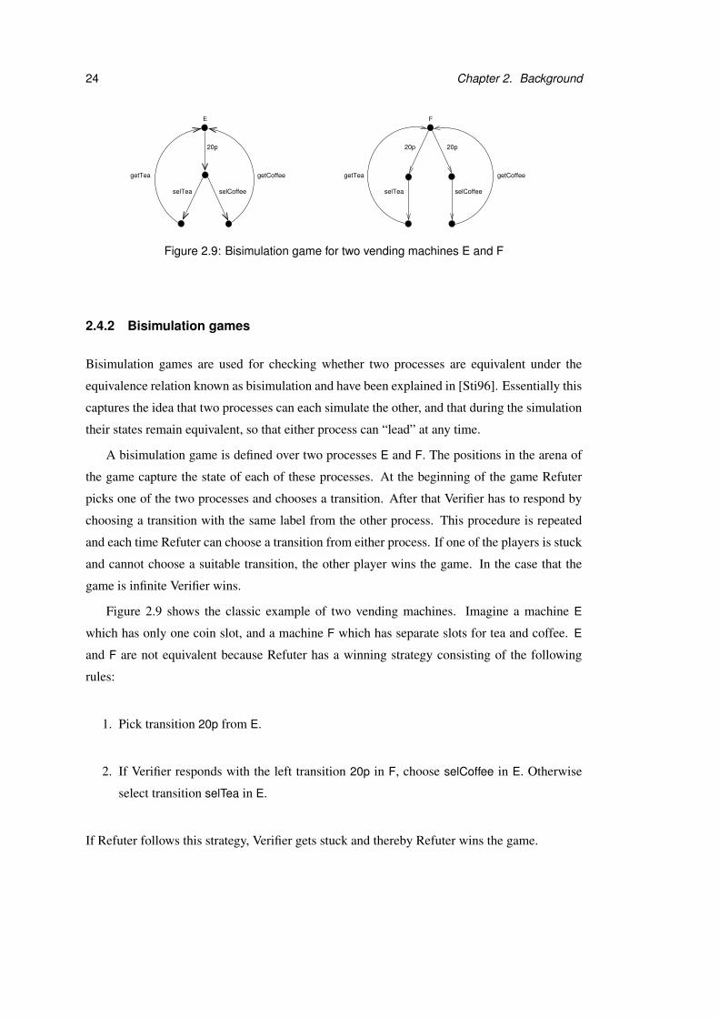
2.4.2 Bisimulation games
Bisimulation games are used for checking whether two processes are equivalent under the
equivalence relation known as bisimulation and have been explained in [Sti96]. Essentially this
captures the idea that two processes can each simulate the other, and that during the simulation
their states remain equivalent, so that either process can “lead” at any time.
A bisimulation game is defined over two processes E and F. The positions in the arena of
the game capture the state of each of these processes. At the beginning of the game Refuter
picks one of the two processes and chooses a transition. After that Verifier has to respond by
choosing a transition with the same label from the other process. This procedure is repeated
and each time Refuter can choose a transition from either process. If one of the players is stuck
and cannot choose a suitable transition, the other player wins the game. In the case that the
game is infinite Verifier wins.
Figure 2.9 shows the classic example of two vending machines. Imagine a machine E
which has only one coin slot, and a machine F which has separate slots for tea and coffee. E
and F are not equivalent because Refuter has a winning strategy consisting of the following
rules:
1. Pick transition 20p from E.
2. If Verifier responds with the left transition 20p in F, choose selCoffee in E. Otherwise
select transition selTea in E.
If Refuter follows this strategy, Verifier gets stuck and thereby Refuter wins the game.
2.4. Formal games 25
2.4.3 Game terminology and formal definition
For the formal definitions in this thesis we refer to Verifier as Player 0 and to Refuter as Player 1.
We write “Player σ” for either of these players and “Player σ” for his opponent.
Definition 2.4.1 (Arena) An arena A = (P,M) consists of a set of positions P, which is par-
titioned into two disjoint sets P0 and P1, and a set of moves M ⊆ P×P. The positions in P0
belong to Player 0, those in P1 to Player 1. We use the notation Pσ to refer to the set of po-
sitions of either of the players, and Pσ for its complement. The set of successor positions that
are reachable by a move from position p ∈ P is defined by succ(p) = {p′ ∈ P | (p, p′) ∈ M}.
Definition 2.4.2 (Play) A play in an arena is a sequence of positions p0 p1 . . . such that pi+1 ∈
succ(pi). At each position pi the player who owns pi has to make a move by selecting a position
from succ(pi). A play is called a finite play if it consists of a finite sequence of positions p0 . . . pn
such that succ(pn) = /0, i.e. there are no further moves possible.
Definition 2.4.3 (Game) A game G = (A, p0,W 0) is given by an arena A, an initial position
p0, and a winning set W 0 ⊆ P∗ ∪Pω of plays, which is determined by the winning conditions
for the two players. A play of G is a play in A that starts at position p0. All plays of G which
are in W 0 are won by Player 0, all other plays by Player 1.
The definition that we have given here is deliberately a very general one. It fits both examples
which have been discussed in Section 2.4.1 and Section 2.4.2. The two players do not have to
take alternate turns, and moves and positions are defined as abstract concepts. In a more precise
game definition the positions may for instance have an inner structure or predicates attached.
We have also left open what kind of winning conditions may be used to determine the winning
set of a game. However, our definition specifies that each play is won by one of the players,
i.e. draws are not permitted.
A strategy is defined by a function which yields the next move on the basis of the play
history and the current position.
Definition 2.4.4 (Strategy) Let A be an arena and fσ : P∗Pσ → P a partial function. A prefix
p0 p1 . . . pl of a play conforms to fσ if for every i with 0 ≤ i < l and pi ∈ Pσ the function fσ
is defined at p0 . . . pi and pi+1 = fσ(p0 . . . pi). A play conforms to fσ if each of its prefixes
conforms to fσ. The function fσ is a strategy for Player σ from p0 if it is defined for all play
prefixes which start in p0 and conform to fσ.

26 Chapter 2. Background
Formally the strategy for Verifier which has been described in Section 2.4.1 is given by
f0(π) =
p7 if π ∈ P∗p1
p8 if π ∈ P∗p8
p9 if π ∈ P∗p3
A special kind of strategies are memoryless strategies. A memoryless strategy does not
depend on the history of a play, but only on the current position. That means f (πp) = f (π′p)
for a memoryless strategy f , prefixes π,π′, and position p. Strategy f0, for instance, is a
memoryless strategy.
Definition 2.4.5 (Winning strategy) Let G = (A, p0,W 0) be a game and fσ a strategy for
Player σ from p0. The strategy fσ is a winning strategy for Player σ if all plays of G which
conform to fσ are won by Player σ.
The existence and computability of winning strategies are of particular importance in for-
mal verification. Games where one of the two players has a winning strategy are called deter-
mined. An important result by Martin [Mar75] is that all games within a particular class called
Borel games are determined. A game is a Borel game if its winning conditions fall into the
Borel topological hierarchy. Details about the definition of this hierarchy can for example be
found in [CMP91] and [Ser04].
In formal verification Borel games have found much attention. For example, games with
winning conditions expressing reachability, safety or liveness properties are Borel games as
explained in [Tho02], [Tho95] and [CMP91]. In the context of this thesis we use the same type
of two-player games with winning conditions that fall into the Borel topological hierarchy as
in formal verification. The effect of introducing decisions by an independent Referee on the
determinacy of exploration games will be considered in Chapter 4, p.64. Notice that different
kinds of games have been used successfully in other areas, both within and outside computer
science, and will be discussed briefly in Section 2.6.
2.4.4 Computation of winning strategies
Winning strategies for many simple game variants played in finite arenas can be computed
by algorithms. As an example we consider the algorithm for reachability games given in
[GTW02], adapted to our notation and presented less formally. For a reachability game with
target set X ⊆ P and initial position p0 the set of positions from which Player 0 has a win-
ning strategy is computed inductively. The basic idea is to work backward from the positions
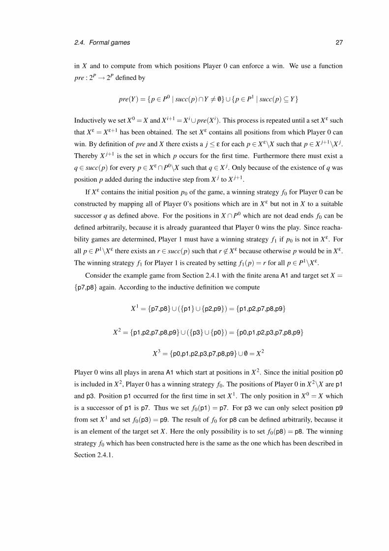
2.4. Formal games 27
in X and to compute from which positions Player 0 can enforce a win. We use a function
pre : 2P → 2P defined by
pre(Y ) = {p ∈ P0 | succ(p)∩Y 6= /0}∪{p ∈ P1 | succ(p) ⊆ Y}
Inductively we set X0 = X and X i+1 = X i∪ pre(X i). This process is repeated until a set X ε such
that X ε = Xε+1 has been obtained. The set X ε contains all positions from which Player 0 can
win. By definition of pre and X there exists a j ≤ ε for each p ∈ X ε\X such that p ∈ X j+1\X j.
Thereby X j+1 is the set in which p occurs for the first time. Furthermore there must exist a
q ∈ succ(p) for every p ∈ X ε ∩P0\X such that q ∈ X j. Only because of the existence of q was
position p added during the inductive step from X j to X j+1.
If Xε contains the initial position p0 of the game, a winning strategy f0 for Player 0 can be
constructed by mapping all of Player 0’s positions which are in X ε but not in X to a suitable
successor q as defined above. For the positions in X ∩P0 which are not dead ends f0 can be
defined arbitrarily, because it is already guaranteed that Player 0 wins the play. Since reacha-
bility games are determined, Player 1 must have a winning strategy f1 if p0 is not in X ε. For
all p ∈ P1\Xε there exists an r ∈ succ(p) such that r 6∈ X ε because otherwise p would be in X ε.
The winning strategy f1 for Player 1 is created by setting f1(p) = r for all p ∈ P1\Xε.
Consider the example game from Section 2.4.1 with the finite arena A1 and target set X =
{p7,p8} again. According to the inductive definition we compute
X1 = {p7,p8}∪ ({p1}∪{p2,p9}) = {p1,p2,p7,p8,p9}
X2 = {p1,p2,p7,p8,p9}∪ ({p3}∪{p0}) = {p0,p1,p2,p3,p7,p8,p9}
X3 = {p0,p1,p2,p3,p7,p8,p9}∪ /0 = X2
Player 0 wins all plays in arena A1 which start at positions in X 2. Since the initial position p0
is included in X2, Player 0 has a winning strategy f0. The positions of Player 0 in X 2\X are p1
and p3. Position p1 occurred for the first time in set X 1. The only position in X0 = X which
is a successor of p1 is p7. Thus we set f0(p1) = p7. For p3 we can only select position p9
from set X1 and set f0(p3) = p9. The result of f0 for p8 can be defined arbitrarily, because it
is an element of the target set X . Here the only possibility is to set f0(p8) = p8. The winning
strategy f0 which has been constructed here is the same as the one which has been described in
Section 2.4.1.
28 Chapter 2. Background
2.5 UML Tools
There are many tools on the market which claim to support modelling with UML. They vary
in their concrete purpose, capabilities and conformance to the UML standard. We differentiate
between two main categories of tools. First, there are tools whose focus is on creating a UML
model. Most of the well-known commercial UML tools belong there. Second, some tools put
an emphasis on checking whether a UML model fulfils certain properties. In this section we
examine a selection of tools for both categories more closely.
2.5.1 Modelling tools
In the simplest case a UML modelling tool only supports the drawing of UML diagrams, such
as, for instance Dia [Dia], SmartDraw [Sma] and Visio [Vis]. The user selects graphic com-
ponents from a library and combines them to create UML diagrams. Usually the modeller is
not much restricted in the way he puts the components together. It is his responsibility to draw
syntactically correct diagrams.
More advanced tools usually force the user to respect the UML syntax to some extent. For
example, the designer may only be able to draw a message between two object lifelines in a se-
quence diagram. Sometimes syntactic consistency between different diagrams is required. For
instance, triggers at transitions in a state machine diagram have to be selected from the opera-
tions or events that are defined within the state machine’s class context. In addition to syntactic
checks ArgoUML [Arg] contains a critique mechanism, which provides feedback about se-
mantic design issues to the modeller. The critique concept for ArgoUML was developed by
Robbins in his PhD thesis [Rob99]. There is, for instance, a critique which points the user to
unreachable states with no incoming transitions in the state machines of the model. Poseidon
[Pos] has been developed on the basis of ArgoUML and thus provides similar functionality.
Semantic checks of the same nature can also be found in Objecteering [Obj]. In contrast to
ArgoUML and Poseidon the implemented checks are not listed in this tool. The designer does
not know which checks are executed and individual checks cannot be switched on or off. The
checks are continuously performed and failures are presented to the user.
Automatic generation of code fragments in different object-oriented programming lan-
guages is one of the main purposes of many UML design tools. Among the tools which are
considered in this section only the basic drawing tools do not provide this functionality. Tools
which generate code have to perform semantic checks to some extent even if they do not put
an emphasis on helping the user to create correct UML models. They have to make sure that
2.5. UML Tools 29
the code which they produce compiles without errors. Hence these tools perform checks which
are dependent on the target programming language and of a more technical nature than the cri-
tiques in ArgoUML and Poseidon. For example, multiple inheritance can be modelled in UML,
but in Java this is not possible. A tool which generates Java code has to check that multiple
inheritance does not occur in the model.
How far the semantic checks for code generation go depends on which parts of the model
are used for this task by the tool. Often the code is generated from the class diagrams only.
Together [Tog] and Rational XDE [Rat] follow this approach. They both put a focus on parallel
creation of UML diagrams and Java code. The modeller can either change the UML model or
the source code, and the tool immediately updates the other part. Together is a UML tool where
model and code are synchronised very continuously and the same concept has also found its
way into Rational XDE. Fujaba4 [Fuj] concentrates on a small subset of UML diagram types.
In addition to class diagrams it uses the information in state machines for the generation of
Java code.
Some tools allow animation of UML state machines, such as Rhapsody [Rha] and Real
Time Studio [Rea]. Animation with Rhapsody works similar to a programming language de-
bugger, but on the more abstract level of state machines. The user selects a state machine which
he wants to observe and generates events. The changes in the diagram are animated and the
modeller can open views to examine the call stack or the event pool. An alternative to manual
event generation is to control the animation by a user-defined GUI or to play through a se-
quence diagram. As in a debugger it is possible to perform the animation step by step or to set
breakpoints. Internally Rhapsody uses its code generation capabilities to animate the model.
It contains a model checking functionality, whose purpose is to discover errors that are prob-
lematic for code generation and animation of the model. The properties which are checked are
predefined and cannot be modified by the user. The checks are performed on a very low tech-
nical level and build heavily on the information in the state diagrams. Thus semantic checks
for animation are usually more complex than those for code generation only. Real Time Stu-
dio has animation capabilities which are similar to Rhapsody’s. In addition to state machines
Real Time Studio can also animate activity diagrams. Moreover it provides a mechanism for
mapping parts of the UML model to hardware components.
The ability to animate a model is often regarded as a means for verification and advertised
as such by tool vendors. The main difference to formal verification is that the animation alone is
4Fujaba is an acronym for “From UML to Java and back again”
30 Chapter 2. Background
not enough to decide about the correctness of the system. The animated execution of the system
is not checked against user-defined properties. Instead the human modeller has to watch the
animation and decide whether the observed behaviour was expected or not.
With respect to this thesis it is of importance that a model can only be animated by existing
UML tools if it contains enough detail and is precisely defined. Usually guard conditions
and actions are formulated in the tool’s target programming language for code generation.
Informally defined guards or incompleteness of the model, such as nondeterminism in state
machines, are not permitted. Restrictions like that make the animation capabilities of these
tools useless for design models at an early stage of the development process. There is no
support for refining a design model gradually, because it is not possible to make changes or
add detail to the model while the animation is in progress. The designer has to finish the
animation, modify the model and then start the animation again from the beginning.
Table 2.1 gives a summary of the tool features which have been discussed here. Moreover
it shows whether a tool is free of charge and which UML version it supports. At the moment
there exist only few tools for modelling in UML2.0 and none of them supports the full range
of diagram types and notational variants of this version. Some tools, such as, for instance
Poseidon, still use an older version of the UML metamodel internally although they provide
support for some UML2.0 features.
Most tools have additional capabilities which have not been mentioned here yet. Among
the most common features are the following: production of documentation in various formats,
storage and version management of models in an integrated repository, export to standard for-
mats such as XMI [XMI02], integration with Java development environments such as Eclipse,
and application of design patterns.
2.5.2 Model checking and evaluation tools
Most of the tools which concentrate on evaluating whether a given UML model is correct,
provide no support for drawing UML diagrams. Instead they require a UML model which has
been created by another modelling tool as input.
Model checking tools for UML usually serve as a bridge between UML and the formal
input language of a model checking tool. The vUML tool [LP99] uses the model checking
tool SPIN to analyse state machines with respect to possible deadlocks. If a deadlock has been
found, the output of the model checking tool is a trace which points the modeller to a concrete
situation where the problem occurs. The approach described in [KE01] follows the same idea

2.5. UML Tools 31
* = smallest edition is freeNS = not specified
ArgoUML
Dia
Fujaba
Objecteering/UML
Poseidon
Real Time Studio
Rhapsody
SmartDraw
Together
Visio
no
no
no
no
Rational XDE no
no
yes*
yes*
yes
yes
yes
1.4
1.3
no
yes
no
yes
yes
yes
yes
yes
yes
no
yes
no
no
no
no
no
no
yes
yes
no
no
no
none
none
syntactic, semantic (animation)
syntactic, semantic (animation)
syntactic,critique mechanism
syntactic, semantic
syntactic, semantic
syntactic,critique mechanism
syntactic, semantic
syntactic, semantic
none
UML Mod
elling
Too
l
UML ver
sion
Free o
f cha
rge
Animati
on
Corre
ctnes
s che
cks
Code g
ener
ation
NS
NS
2.0
2.0
2.0
NS
NS
1.4
NS
Table 2.1: Properties of UML modelling tools
but uses the model checking tool LTSA to detect deadlocks. Since it is focused on middleware
it considers multi-threading and allows several objects to run in the same process.
HUGO/RT [Hug], [KM02] translates a UML model into a formal model that can be used
as input for SPIN and real-time model checker UPPAAL. In addition to the checks that can
be performed by the tools mentioned before HUGO/RT verifies whether desired (or undesired)
behaviour specified by UML interaction diagrams can be realised by state machines. For ar-
chitectural models the same functionality is part of the Charmy tool, which is presented in
[IMP01] and also uses SPIN as external model checking tool. This approach is not based on
UML but on different variants of sequence and state diagrams.
A general framework for transforming UML models into formal language specifications as
required by model checking tools is presented in [MC01]. This work is based on homomorphic
mappings between the UML metamodel and the metamodel for the target language. The usage
of the framework is illustrated on a translation from UML class diagrams and state machines
to the input language of SPIN.
There exist many other formalisations of UML state machines with the purpose of using
tools for simulation and verification. For UML state machines, for example, [BCR02] presents
a formalisation by abstract state machines which can be simulated by the tool AsmGofer. In
[Kwo00] UML state machines are mapped to the input language of the model checking tool
SMV using rewrite rules.
32 Chapter 2. Background
One of the most interesting tools for the evaluation of OCL constraints in the context of this
thesis is USE [Use] (UML-based Specification Environment), because it supports and requires
interaction with the user. USE is a stand-alone tool which validates OCL constraints over
system states given by a collection of objects and links. The designer first has to provide a
textual description of a UML class diagram and can then create objects and links according
to this structure. OCL constraints also have to be entered manually and are evaluated for the
current system state. The user has the possibility to manipulate the system state by various
basic operations. This is particularly important for the evaluation of pre- and postconditions.
First, the precondition is validated for the current system state. Second, the designer has to
simulate the execution of the corresponding method and enter the state of the system after the
termination of the method. Finally, the postcondition is checked for the new system state. The
current system state can be displayed as object diagram in the graphic view of USE and the
method calls that are simulated by the designer are visualised in a sequence diagram.
The theoretical background of the USE tool is presented in the PhD thesis [Ric02] by
Richters. Parts of this thesis have also been published in [RGG98] and [RG99]. The suggested
set-theoretic OCL semantics serves as basis for the definition of a metamodel for OCL. This
metamodel has been used as foundation for the most recent OCL specification [OCL03].
The KeY Tool [KeY] is an add-on to the UML modelling tool Together [Tog]. It contains
templates and patterns which allow comfortable specification of OCL constraints. KeY can
analyse whether a set of constraints is consistent and free of contradictions. Furthermore the
tool can be used to verify code against the constraints. The programming language that is
considered for this is Java Card. In contrast to USE the OCL constraints are not evaluated on
design but on implementation level.
The formal basis for the KeY tool is dynamic logic. An overview on the tool and its
foundations is given in [ABB+05]. There are many publications on the formalisms used at
different stages of the project, both for the analysis of constraints and the verification of Java
Card programs. We refer to the KeY project webpage [KeY] for a detailed list.
The Kent Modelling Framework [KMF] is a general approach to the evaluation of OCL
constraints which is not restricted to UML. A metamodel of a modelling language has to be
provided as input for the tool. After that an instance of the metamodel can be loaded and OCL
constraints may be evaluated with respect to this instance.
2.6. Related work 33
2.6 Related work
UML was developed to solve practical problems in software engineering. It aims to be intuitive
and easy to use in order to allow quick communication about software systems in a standardised
form. On the other hand it is required to be expressive, extensible and precise at the same
time. The semi-formal approach which is followed now can be seen as a trade-off between
these goals. A strong disadvantage of this solution is that the UML standard specification is
ambiguous at some points and allows different interpretations. That makes the implementation
of tool support for UML more difficult and results in tool-dependent dialects of UML.
The Precise UML group [pUM] consists of researchers and practitioners who attempt to
clarify the semantics of UML. This group is also interested in developing techniques for rea-
soning about UML models, verifying the correctness of UML design, and constructing tool
support for the rigorous application of UML. There are different approaches to making UML
more precise. One solution is to clarify the natural language descriptions in the semantics part
of the UML standard and to add more OCL constraints to it. Another possibility is to map UML
to formalisms which give UML a precise semantics. Because of the complexity of UML, none
of the existing formalisations covers it completely. The focus is often on a specific diagram
type and usually not all diagram features are considered.
Here we concentrate on related work for UML state machines which have a long history
and were originally not object-oriented. They were first introduced by Harel in [Har87]. Later
Harel et al. made this technique more precise [HPSS87] and extended it to object modelling in
[HG97]. This work was used as basis for defining UML state machines. The terms statechart
and state machine are often used interchangeably in the literature, and there is a large amount
of work on formalising state machines in many variants including UML.
A formalisation of UML state machines using labelled transition systems and algebraic
specifications written in the specification language CASL is presented in [RACH00]. Labelled
transition systems are also suggested as formalism in [vdB01], where a structured operational
semantics is defined for this diagram type. Graph transformations are used as formal basis in
[GPP98] and [Kus01]. In the approach described in [LMM99] state machines are first mapped
to extended hierarchical automata and then a semantics for these specific automata is defined
in terms of Kripke structures. In [TS03] and [TS05] two formally defined variants of state
diagrams are used in a complementary way to solve a problem with recursive calls in the UML
semantics.
34 Chapter 2. Background
Often the formalisation of UML is not only motivated by making its definition more pre-
cise, but by the desire to use existing model checking tools. A summary of work on translation
of UML diagrams into the formal input languages of model checking tools has already been
given in Section 2.5.2 where UML tool support has been discussed.
The formal work on UML which has been regarded so far refers to UML models which
are very detailed and unambiguous. This thesis is focused on the incremental improvement of
UML design models which are incomplete and contain informal parts. The modeller adds grad-
ually more detail to a partial design by playing a game with it. Modification and verification of
the model are both part of the game and are intertwined with each other.
The work by Harel et. al. on “play-in play-out scenarios” [Har01], [HKMP02] has a similar
flavour to our work, and is motivated by similar concerns about the interactivity of tools to
support design. Play-in scenarios allow the capture of requirements in a user-friendly way.
The user specifies what behaviour she expects of a system by operating the system’s graphic
user interface (GUI) – or an abstract version thereof – which does not have any behaviour or
implementation assigned to it yet. A tool which is called the play-engine transforms the play-in
of the user into live sequence charts (LSCs), which are used as formal requirements language.
The user does not have to prepare or modify the LSCs directly but only interacts with the GUI.
In contrast to UML sequence diagrams, which are existential, LSCs can be either existential
or universal. A universal LSC defines restrictions that have to hold over all system runs, while
an existential LSC represents a sample interaction which has to be realised by at least one
system run. Using play-out scenarios we can verify whether a set of LSCs – created by play-in
scenarios or in any other way – meets the system requirements. Thereby the user feeds the GUI
with external environment actions rather as though he were testing the final system. For each
user input the tool computes the response of the system on the basis of the LSCs in terms of
a sequence of events which are carried out. The system response is called a superstep and it
is correct if no universal LSC is violated during its execution. The task of finding the desired
superstep can be formulated as a verification problem. In [HKMP02] a translation of LSCs into
transition systems which allows the usage of model checking tools for the computation of the
supersteps is given. Similarly model checking can provide the answer to the question whether
an existential LSC can be satisfied.
This approach differs from ours in that its focus is on capturing and testing the requirements
while we are mainly interested in helping the user to design a system. Thus play-in play-out
scenarios do not aim to help in defining intra-object behaviour, as our games do, but remain on

2.6. Related work 35
the higher level of interaction between objects and user. Since our work concentrates on UML
we use the diagram types provided by it, i.e. UML sequence diagrams instead of the more
expressive LSCs.
The work on implied scenarios by Uchitel et. al. [UKM04] is related to ours in that it de-
scribes a process of incrementing scenario-based specifications and behavioural models. This
process defines a way to synthesise three different formal behaviour models from a set of pos-
itive and negative scenarios which are given as input. The behaviour models yield a set of
implied scenarios which are then analysed by the model checking tool LTSA. The result of the
model checking determines whether an implied scenario should be added to the set of positive
or negative scenarios, which is extended incrementally. In contrast to our approach the incre-
mentation by implied scenarios does not involve interaction with the user to resolve uncertain
situations and experiment with the design. Furthermore the foundation for the creation of the
behavioural models are message sequence charts, not different combinations of UML diagrams
as for our exploration games. Except for the model checking step the incrementation process
based on implied scenarios does not seem to be supported by a tool, i.e. the synthesis of the
formal models from the scenarios is not automated.
Coloured Petri Nets [Jen97], [ERRW03] are a well-known technique for modelling concur-
rent systems. The system behaviour is simulated by movement of tokens in the net structure.
The tokens are coloured and represent data values. Simulation tools for Coloured Petri Nets
support the user in playing through the net and can check invariants or properties like liveness.
They are similar to our GUIDE tool in that they usually provide an interactive mode which
allows the user to influence the “token game”. The user is asked for variable bindings and
decides which transition should be taken if two or more compete for the same tokens. How-
ever, in contrast to exploration games the modeller cannot act in different roles or increment
the model during the simulation.
An example of a less formal technique where the modeller plays and experiments with the
design are CRC-cards [BC89]. CRC stands for Class-Responsibility-Collaborator. A CRC-
card represents an object and contains its class, the responsibilities it has to fulfil, and the
objects with whom it communicates. The cards are used to play through scenarios. This can be
done by one person or by a small group of people. In case of a group each member plays the
role of one object represented by a card. During a CRC-card session cards may be modified,
removed or added.

36 Chapter 2. Background
On a very abstract level the whole software development process can be regarded as an
interactive game. In [Coc02] agile software development is considered as a “cooperative game
of invention and communication”. The software developers play the game with two goals in
mind. The primary goal is the delivery of a working software product, and the secondary
goal is to prepare the next game. Non-cooperative games can be used as metaphor for design
reviews where one player defends the design and the other players try to find a flaw in it. An
adversarial attitude like this has also been successfully adopted by the Black Team [DL87] for
testing software systems.
As far as we know games have not yet been applied in a more concrete way to the software
design process. In particular there exist no approaches where games are used to explore a UML
model as introduced in this thesis. However, two-player games which are similar to the ones
considered in this thesis have been frequently used in the area of computer science. They were
first regarded in the context of automata theory and system synthesis.
Formulated by Church in [Chu63], the synthesis problem is the task of constructing a sys-
tem that satisfies a given specification on all possible inputs. Buchi and Landweber solved an
open case of this problem in [BL69] using games. They presented an algorithm which decides
whether there exists a finite automata solution for a condition given in the the monadic sec-
ond order theory of one successor. If a solution exists, it is produced by the algorithm. Using
game terminology this result means that finite-state games are determined (see also [TB73],
for example). Many alternative solutions have been developed later, such as, for instance, an
approach based on tree automata [Rab72].
Originally focused on hardware, system synthesis was later applied to the construction
of software modules and controllers. In [PR89] an approach for reactive systems and spec-
ifications in the linear temporal logic LTL is explained. A solution to the questions when a
specification given as an LTL formula is realisable, is presented in [ALW89]. These results are
extended to systems with incomplete information and specifications in the branching temporal
logic CTL∗ in [KV99]. Distributed systems and CTL∗ specifications are considered in [KV01].
An approach for the synthesis of deadlock free connectors for COM/DCOM applications using
CCS-like process algebra is presented in [IT01].
A closely related area is that of controller synthesis, which can be expressed as a game
played between Control and Environment on an open system. The question of interest is
whether Control has a strategy which enforces the system to behave according to a given spec-
ification independent of what Environment does. Finding a winning strategy (the controller)

2.6. Related work 37
for player Control is known as the control problem. Like system synthesis the control prob-
lem has been examined for different kinds of systems and logics. Recent work covers, for
instance, discrete event systems [MT02], synchronous systems [dAHM00], [dAHM01b] and
systems in reactive environments [KMTV00], where the environment can disable different sets
of responses when reacting with the system. In case that there exists a controller for a given
combination of system and specification it is also of relevance whether the controller is finite
and how big it is. Games in this context are usually infinite and there are some classes of speci-
fications which are of particular interest. An example for such a kind of specification or “game
objective” is that eventually an element of a given target set of system states has to be reached.
Some frequently occurring game objectives, corresponding winning strategies and complexity
results are presented in [Tho95].
The point of view taken in verification is slightly different. Here the aim of playing a game
is not the construction of a system, but to check whether a system fulfils the specification. For
an overview on model checking in general see, for instance, [CGP99]. A survey on how model
checking can be used for debugging UML designs is given in [dMGMP02]. The relationship
between games in controller synthesis and verification is pointed out in [dAHM01a], where a
translation of a game objective from controller synthesis into a fixpoint formula written in the
mu-calculus is defined.
In game theory the model checking problem amounts to finding a winning strategy for
the corresponding model checking game. The advantage of the game view is that it is very
intuitive and sometimes leads to fast algorithms. Algorithms for computing winning strategies
have been considered for different kinds of logics. Lange’s PhD thesis [Lan02] describes how
games are used to solve the model checking problem for modal and temporal logics. It also
considers games for checking the satisfiability of formulas and complete axiomatisations for
these logics.
For games with fixed finite arenas the idea of taking uncertain situations into account for
the computation of winning strategies has been introduced in [dAHK98]. Therein winning
strategies for concurrent reachability games where the two players move simultaneously are
discussed. The target position of a move is uncertain because it depends on the choices of both
players.
An approach to games with infinite arenas are abstract games as described in [Ste98a],
[Ste98b]. In an abstract game the positions and moves are (possibly infinite) sets of positions
and moves of a concrete game. An abstract game can be defined in such a way that a win-
38 Chapter 2. Background
ning strategy for it is also valid for the underlying concrete game. Winning strategies can be
computed by a generic on-the-fly algorithm which works on a variable level of abstraction and
explores the abstract game.
Most model checking tools like SPIN or SMV are based on automata theory. A tool which
uses games as underlying technique is the Edinburgh Concurrency Workbench [Edi]. It exploits
the game view of verification questions and computes winning strategies. The user asks a
question, the tool calculates a winning strategy for the game, and then offers to take the winning
part in a game against the user. The user finds that, no matter which moves he chooses, the tool
always has an answer: the user can only lose. Thus the tool helps the user to get an intuition
about why the answer to the question is as it is. More detail about the model checking approach
used for the Edinburgh Concurrency Workbench can be found in [SS98].
Combinatorial games are played by two players who move alternately and cannot hide
information from each other. The game is won by a player or ends with a tie. This kind of
game is used to represent, analyse and solve problems in complexity, logic, graph theory and
algorithms [Fra02]. An example for a combinatorial game with a lot of publications in the area
of artificial intelligence is chess. Another area where two-player games have been successfully
applied is finite model theory [Hod93], [EF95].
In contrast to games in formal verification the type of game used for modelling distributed
systems [AH94, Chapter 38], [Hal03], [FS03] usually involves more than two players. The
players represent independent agents which may possess certain information and act selfishly.
They receive variable payoffs instead of simply winning or losing. A move which leads to
a better payoff for one player may have a negative effect on another player’s payoff. Thus a
strategy which optimises one player’s payoff can depend on the strategies followed by other
players. The design of an algorithmic distributed mechanism as described in [FS03] amounts
to finding a formula for the payoffs that the agents receive such that system-wide goals are met.
This style of games is the same as in economics, where game theory has its origin. In this
area the players are often human and it is particularly hard to predict their behaviour, which is
the major problem with payoff optimisation. There exist many textbooks on the foundations of
game theory as used in economics, such as, for instance, [Bin92], which summarise the most
important results. Aumann and Hart give an extensive account of game theory in [AH94] which
is focused but not restricted to economics. The application of games in many other disciplines
is also covered in this work.

Chapter 3
Games for UML software design
The overview on UML tools in Chapter 2 has shown that there does not exist much support
for design exploration. Some UML tools help the designer to examine a UML model by an-
imation or verification. However, these tools require very precise models as input and do not
permit interruptions of the examination process in order to adapt the design. The aim of this
thesis is to fill this gap and to develop concepts for tools which help the modeller to explore
a design solution and gradually add more detail to it. The idea is to let the designer attempt
a verification of the design model, even though the model might not contain all information
that is needed for full verification. While the verification is in progress, the designer provides
additional information and may modify the design. In this chapter we will argue that games
are a suitable technique for this purpose. We give an informal description of exploration games
and demonstrate their usage with an example. Finally we discuss the desired features of a tool
which supports games with UML design.
3.1 Why games with UML?
Games have been chosen as foundation for this thesis because they offer several advantages.
First, playing a game does not require background knowledge in formal methods and is fairly
intuitive. The basic idea of two players Verifier and Refuter who compete against each other to
prove the correctness of the design or detect a flaw in it is easy to grasp. Since the concepts of
this thesis are targeted at improving tool support for mainstream software designers, this has
been an important factor for choosing the formal foundation.
39
40 Chapter 3. Games for UML software design
Another advantage of games with respect to tool support is that they are an interactive
technique, which allows the modeller to influence a play. The progress of a play is determined
by the decisions of the players who react to each other’s moves, and by the Referee. These
roles can be played by the designer, who may also increment the game definition as Explorer
during a play.
Such an incremental development of a game is the central idea of this work. Since the
design and the specification of the system are both incorporated in the game, the designer can
increment each of those parts. For example, suppose that the design model is complete, but
that there is only limited understanding of what it means for the design to be correct. Perhaps
it has not yet been understood how the informal specification of overall system requirements
should be translated down into precise requirements; or perhaps the informal specification is
itself incomplete or incorrect. In mainstream business software development, which is our main
focus of concern, both are likely to be the case. The game as initially defined by the modeller
may incorporate only a small amount of information about what it means for the design to be
correct: it may be “too easy” for Verifier to win the game. The modeller should be able to
improve the game to make it a better reflection of the correctness of the design. This might
include, for example, changing the winning conditions so that plays which would have been
won by Verifier are won by Refuter in the new game. At the same time, it is likely that the
design itself is too incomplete to permit full verification. The modeller should also be able to
change the game by adding more information about the design.
This idea fits very well with iterative and incremental software development processes as
introduced in Chapter 2 where the specification is updated along with the artifacts describing
the system design. Thus games are a very natural choice with respect to how software is usually
developed. The designer increments the game while it is being played and has to ensure that
the game is challenging for the two players. A sequence of such incrementations, which may
be part of different plays, is an exploration of the design and its specification. Even though the
incrementations of the game may be beneficial for one player, the modeller is not necessarily
biased. During one play the designer may first increment the game such that it becomes easier
for Refuter, and later explore a different part of the game which increases Verifier’s chances of
winning.
The advantage of permitting game incrementation during a play is that the designer does
not have to start a new play from the beginning but can continue the improved game from the
current position. However, the disadvantage is that an incrementation may invalidate the play.

3.1. Why games with UML? 41
D0=>D1
D0=>D2
Design D0, Specification S0
Game G0:
S0=>S1
...... ...
Game G4:Design D3, Specification S0 Design D1, Specification S2
Game G5: Game G6:
... ... ...
S0=>S2D1=>D3
Design D2, Specification S1
S0=>S1 D0=>D2
...
Game G2:Design D2, Specification S0
...
Game G1:Design D1, Specification S0
...
Game G3:Design D0, Specification S1
... ... ...
Figure 3.1: Repeated game incrementation
For example, moves of the old game may not be part of the incremented version anymore. Even
if all moves of the play still exist after the exploration, there is no guarantee that the players will
select the same moves as before when the play is repeated from the beginning. Thus a winning
strategy for the old game does not necessarily work in the incremented game and may have to
be adapted. A formal definition of invalid play histories will be given in Chapter 4, p.70. In the
GUIDE tool the user can specify whether the Explorer is allowed to make incrementations that
invalidate the play.
Figure 3.1 illustrates how different plays of game G0 initiate different explorations. The
new versions of the game are further improved which leads to new variations and combina-
tions of design and specification. Incrementing the game will in most cases correspond to
adding more detail to its parts. That means both specification and design become gradually
more precise. Hence this approach provides the possibility to progress smoothly from informal
exploration of decisions to full verification. This has the potential to lower the commitment
cost of using formal verification. The designer can stop exploring if he believes that design and
42 Chapter 3. Games for UML software design
specification are precise enough for his purpose. Playing the game again from the beginning
without further incrementations helps to verify the current design against the current specifi-
cation. The designer may still have to provide information during the verification process if
the game is too incomplete at some points, which is very likely with UML design models as
basis. However, it is not necessary to improve the game so far that the complete system can be
verified formally without the help of the designer.
Finally, games may have another advantage: games which people play in their free-time are
played for fun. The question is whether games that are played with the purpose of exploring
design decisions are also to some extent entertaining. If so, a game-based design tool may
actually make the work of software designers more enjoyable.
3.2 Exploration games
An exploration game is defined by a game arena, an initial position, responsibility assignments
for the different stages of each move, game settings, winning conditions for the players, and
possible incrementations by the Explorer. The game arena consists of positions and moves. It
draws information from particular parts of a UML design model – in our example from UML
state machines and class diagrams. A move may have a precondition and parameters. The
preconditions of the move do not have to be specified formally. If they are based on constraints
in the UML model they are very likely to be formulated in natural language. The participants
in an exploration game are the two players Verifier and Refuter, the Referee and the Explorer.
A move is selected in the following steps:
1. Precondition evaluation. The set of legal moves from the current position is determined
by declaring which informally specified preconditions are assumed to be true.
2. Choice of move shape. A move shape is a set of moves which have the same source
position, name, precondition and parameter signature. The moves belonging to a move
shape only differ in their parameter values and target positions. Only legal move shapes
may be selected in this move step.
3. Parameter provision. The move shape is reduced by fixing the parameter values for the
move. If only one single move is left, the next move has been selected and the last step
is obsolete.
3.2. Exploration games 43
4. Resolution of non-determinism. There may be more than one move which belongs to the
selected move shape and has the chosen parameter values. These moves only differ in
their target positions and one of them has to be picked as next move.
In contrast to formal models that are normally used as basis for verification games, UML
models are most unlikely to define a unique system, complete in all detail. In the exploration
game framework the game participants resolve any kind of non-determinacy during a play. The
responsibility for performing the four different move steps are assigned to Refuter, Verifier or
the Referee. In contrast to the players the Referee does not benefit from decisions about the
progress of the play.
The game settings can be general or specific for one variant. They are used for two pur-
poses. First, they fix an interpretation of the UML semantics where necessary. UML contains
“semantic variation points” for some of its features which provide a degree of freedom in its
interpretation. Since the possible moves in a game depend to a great extent on the UML seman-
tics, the designer has to decide how such semantic variation points should be treated. Second,
the game settings may impose restrictions on how the game is played and incremented. For ex-
ample, the game settings can specify a move limit and thus determine the maximum length of a
play. Furthermore the game settings define whether the Explorer may increment the game in a
way that violates the play history. Game settings will be discussed in more detail in Chapter 5.
The Explorer’s goal is to make the game more precise and keep the balance between Refuter
and Verifier. He is allowed to adjust the difficulty of the game for the players by incrementing
the game definition during a play. Apart from incrementing the game the Explorer may also
backtrack in the play history or change the current position. The role of the Explorer is always
played by the human designer who has enough knowledge about the system to choose sensible
incrementations and make the model more precise. Additionally the modeller may take on
other parts in the game, such as, for example, the role of one of the players to examine the
design from a particular perspective.
Incrementations are defined with respect to the UML model for all parts of the game where
this is possible. Thus the designer does not work with the game definition, but increments these
parts of the game indirectly via changes in the UML model. After he has performed such an
incrementation as Explorer, the play is continued according to the new game definition.
44 Chapter 3. Games for UML software design
enrol(s:Student)addToWaitingList(s:Student)addToParticipants(s:Student)
name: String
Module
matriculate()
Student
addModule(m:Module)
0..*
0..*
waitingFor
modulesparticipants
0..*
waitingList {ordered}
0..*
matNo: int
minParticipants: intmaxParticipants: int
Figure 3.2: Example class diagram
Student
EndOfYear[else]
t3:EndOfYear
t4:matriculate()
matriculate()
t2:StartOfYear
t5:
t6:
t1:addModule(m:Module)
Enrolling Studying
Taking Exams
ProposedScheduled
EndOfYear StartOfYear
Module
t7:
t9:t10:
Open
t8:
s.addModule(self)enrol(s::Student)/
Being Taught
[practicals passed]
On Holiday
Figure 3.3: State machines for Module and Student
3.2.1 Example of an exploration game
For our example game variant we assume that a UML model for a university course registration
system consisting of the class diagram in Figure 3.2 and the two state machines shown in
Figure 3.3 is given. The class diagram is a simplified version of the one that has been introduced
in Chapter 2. Notice that the guard conditions in the state machines are informally specified.
During a play of this game a collection of objects is observed with respect to state changes.
The objects constitute the system which is verified. Here we consider a student Joe and a
module CS1.
Positions: A position represents a snapshot of the system and consists of the following parts:
• For each object
– a state configuration,
– and an event pool.
• A set of parameters which are in scope at the position.

3.2. Exploration games 45
The positions where all event pools are empty belong to Refuter, all others to Verifier. At the
initial position all objects are in their default states and the event pools are empty.
Moves: In this example the moves from Refuter’s positions correspond to generating events.
All events which refer to an operation in the class diagram are regarded as call events and are
targeted at a specific object. When a call event is generated a target object has to be speci-
fied and the event is put into its event pool. The call events in our example are matriculate,
addModule, enrol, addToWaitingList and addToParticipants. All other events that occur in the
state machines are considered as signal events. They are broadcast to all objects and put into
their event pools when generated. If an event is parameterised suitable parameter values have
to be provided for it.
A move from one of Verifier’s positions corresponds to firing a set of state machine transi-
tions according to the UML semantics. For each object the first event in its pool is dispatched
and an enabled state machine transition is fired, if there is any. An event which does not trigger
any transitions is discarded as specified in the UML standard [UML03b][p.492]. Whether a
transition is enabled or not depends on the evaluation of the guard condition at the time when
the event occurs. Thus the legality of a move is determined by the evaluation of the guards,
which are considered as preconditions of the move.
If a transition is fired and an effect is attached to it, another event is generated. The new
event is put into the appropriate event pool and the object completes its transition. This cor-
responds to the idea of asynchronous actions in UML, where the object does not have to wait
until the new event has been processed before it reaches the next stable state.
Figure 3.4 shows some of the positions and moves of our example game. Refuter’s posi-
tions are shown in grey-shaded rectangles and are labelled by “R”, Verifier’s are labelled by
“V”. The position shown as p0 is the initial position.
Winning conditions: Refuter wins a play if a position is reached where CS1 is in state Open
and Joe is in state Taking Exams. He also wins all plays which end at a position belonging to
Verifier because no further moves are possible. Verifier wins all other plays.
Because of the informally defined guard conditions at the transitions it is unclear for some of
the moves whether they should be regarded as legal or not. For this example we assign the
responsibility for deciding about the legality of moves to Verifier. Furthermore we assume that
the players select move shapes at their own positions. They also provide parameters and re-
solve non-determinism for all moves emerging from the positions belonging to them.
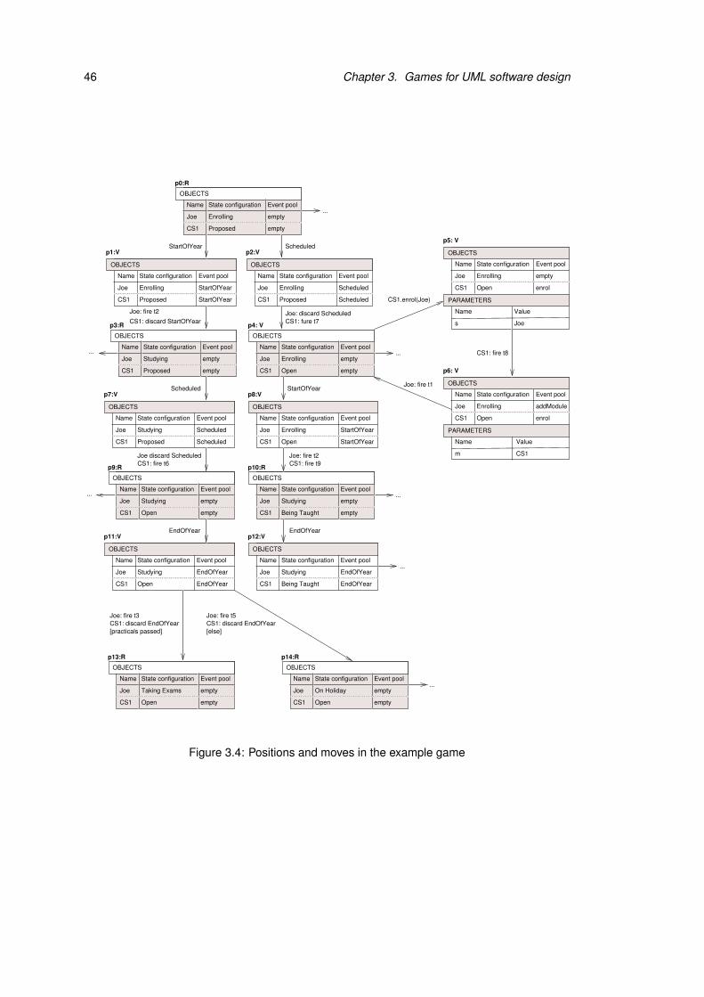
46 Chapter 3. Games for UML software design
CS1 CS1
CS1
...
...
...
...
...
Joe: discard ScheduledCS1: fure t7
CS1.enrol(Joe)
Joe: fire t1
StartOfYear Scheduled
CS1
CS1
CS1 CS1
EndOfYear
EndOfYear
EndOfYear
EndOfYear
...
...
StartOfYear
CS1: fire t9Joe: fire t2
EndOfYear
CS1 CS1
EndOfYear
CS1: fire t6Joe discard Scheduled
Scheduled
CS1: discard StartOfYear
Joe: fire t2
CS1
s
CS1
m
Joe
CS1
CS1: fire t8
CS1
CS1 CS1
CS1
State configurationName
Joe Enrolling
Proposed
Event pool
StartOfYear
StartOfYear
p1:V
State configurationName
Joe Enrolling
Proposed
Event pool
Scheduled
Scheduled
p2:V
State configurationName
Joe
Proposed
Event pool
p7:V
Studying Scheduled
Scheduled
State configurationName
Joe Enrolling
Event pool
StartOfYear
StartOfYear
p8:V
Open
State configurationName
Joe
Event pool
empty
emptyStudying
p10:R
Being Taught
State configurationName
Joe
Event pool
Studying
State configurationName
Joe
Event pool
Studying
p11:V p12:V
Open Being Taught
[else]
State configurationName
Joe
Event pool
empty
empty
Open
p13:R
Taking Exams
State configurationName
Joe
Event pool
empty
empty
Open
p14:R
On Holiday
State configurationName
Joe Enrolling
Event pool
empty
Name
enrol
p5: V
State configurationName
Joe Enrolling
Event pool
Name
enrol
p6: V
addModule
Value
Value
Open
Open
[practicals passed]
State configurationName
Joe
Event pool
empty
emptyStudying
p9:R
Open
State configurationName
Joe
Proposed
Event pool
empty
empty
p3:R
Studying
State configurationName
Joe Enrolling
Event pool
empty
empty
p4: V
Open
State configurationName
Joe Enrolling
Proposed
Event pool
empty
empty
p0:R
OBJECTS OBJECTS
OBJECTS OBJECTS
OBJECTS
OBJECTS OBJECTS
OBJECTS OBJECTS
OBJECTS
PARAMETERS
OBJECTS
PARAMETERS
OBJECTS
OBJECTS OBJECTS
OBJECTS
Joe: fire t5CS1: discard EndOfYearCS1: discard EndOfYear
Joe: fire t3
Figure 3.4: Positions and moves in the example game

3.2. Exploration games 47
Responsibilities:
• Verifier decides whether an informal precondition of a move is assumed to be true.
• Verifier and Refuter fulfil all other tasks at their own positions and for the moves emerg-
ing from these positions.
Game settings: According to the UML semantics an event is always discarded if it does not
trigger a transition. Here we introduce a setting which specifies whether this solution should
be applied to call events. For this example game we assume that discarding call events is
forbidden.
Incrementations:
• Add or delete a state transition.
• Add or delete a state. If a state is deleted, all transitions which emerge from or lead to it
are also deleted.
• Add or delete an event or operation.
• Change the guard condition at a transition.
• Change the winning conditions.
• Change the responsibility assignments.
• Change the game settings.
Notice that the first four incrementations all operate directly on the parts of the UML model
which have been used as basis of the game definition for our game variant. The last three
incrementations are more general and transferable to other game variants which do not use
UML state machines and class diagrams as foundation.
The game variant which has been introduced here is a simple example of an application of
exploration games to UML in order to illustrate the approach. We have abstracted from details,
such as, for instance, how exactly the winning conditions and responsibilities are defined. Since
the positions of the game only record the abstract states of the objects, it is difficult to evaluate
sophisticated guard conditions. For example, it is not possible to decide whether the number of
students who are enrolled in a module exceeds the maximum number of participants. In order to
evaluate a precondition like this we would have to define a more complex game variant whose
48 Chapter 3. Games for UML software design
positions contain the objects’ attribute values and links. For our example game preconditions
whose evaluation is undefined because the positions do not contain enough information are
treated as if they were informally defined. The game participants have to decide whether their
evaluation is assumed to be true or false.
A UML model may be used for more than describing the current system model of a game.
In the example above the arena of the game was built up exclusively on the basis of the state
machines and the class diagram. Refuter, who represents the environment, may generate events
in arbitrary order without any restrictions in this game. It is very unusual to take all possible
combinations of events into account as we did in this example. A common approach in UML is
to model the most important and interesting scenarios by sequence diagrams. These diagrams
can be used to restrict Refuter’s moves. Refuter has to pick sequence diagrams during a play
and must move accordingly. Alternatively Refuter’s moves may be restricted by protocol state
machines. These game extensions are discussed in detail in Section 5.3, p.143. The UML
model may also contain information that can help the designer to formulate winning conditions
of the game. For example, OCL invariants or sequence diagrams describing undesired system
behaviour may induce winning conditions for Refuter. If an invariant is violated or an undesired
sequence has been performed, Refuter wins the play.
3.2.2 Plays without exploration
The purpose of playing a game without exploration is to check whether a particular scenario
violates the system specification. Thus plays of this kind correspond to walkthroughs as known
in software engineering (see Section 2.3, p.21). The players determine how the walkthrough is
continued in each of their moves. Thereby they have to respect the responsibility assignments
that are part of the game definition. If Refuter has a winning strategy, he can always provide
a scenario that violates the system specification expressed by the winning conditions. In the
case that Verifier has a winning strategy, all walkthroughs which are permitted according to the
game definition respect the specification.
We examine some example plays of our game that do not involve incrementations by the
Explorer and consist of the positions shown in Figure 3.4. Assume that Refuter challenges by
StartOfYear at position p0. Verifier has only one choice to respond to this challenge and moves
to p3. From there Refuter’s next moves are Scheduled and EndOfYear. Again Verifier has only
one possibility to react to these events and the play continues from p3 via p7 and p9 to p11.
Here Verifier has for the first time the chance to actually select a move. Before she can do

3.2. Exploration games 49
this she has to decide which of the moves are legal. The guard condition else at transition t5
indicates that exactly one of the transitions triggered by EndOfYear must be enabled, i.e. the
guard conditions are mutually exclusive. That means only one move emerging from p11 can
be declared as legal. Verifier realises that she will lose the play if she moves to p13, because
this position fulfils the winning condition for Refuter. Hence a rational choice for Verifier is
to declare that the move to p14 is legal. If she selects this move, she can avoid losing the
play. In fact, if Verifier applies this strategy every time position p11 is visited, she can win all
plays. That means Verifier has a winning strategy and the design is considered to be correct
with respect to the specification under the current game definition.
Verifier wins this variant of the game so easily because she can always avoid firing transi-
tion t3. At an early stage of the design phase, it may be useful to give Verifier so much power.
This game variant is suitable for playing through the desired scenarios of the system without
being forced to consider preliminary parts of the design or special cases. A variant of the game
which is maximised for detecting flaws should allow Refuter to decide about the validity of
informal preconditions. In the example play described above Refuter will then declare that the
move to p14 is illegal. Thus Verifier is forced to move to position p13 where Refuter wins
the game. If the Referee is responsible for evaluating informally defined preconditions, the
outcome of each play is uncertain. Neither of the players has a safe winning strategy because
the decision of the Referee at p11 determines who wins the play.
3.2.3 Plays with exploration
If a game is played with exploration, the walkthrough that is performed by the players may be
interrupted by the Explorer. The Explorer can add more detail to the game definition, which
includes the design model and its specification, at any time. After an incrementation has taken
place the players have to continue the walkthrough with the new version of the design model.
In this section we use the example game from Section 3.2.1 again to show how a game is
repeatedly changed by incrementations. During the explorations the state machine for Module
will be altered. The result of all explorations considered here is shown in Figure 3.5. As
before we will refer to positions that are part of the arena excerpt shown in Figure 3.4 in the
descriptions of the example plays.
Assume that Refuter challenges by StartOfYear, Scheduled and EndOfYear from the initial
position. Verifier applies her winning strategy and moves to p14. At this point the designer
realises that the game is too easy for Verifier. This discovery urges him to increment the game
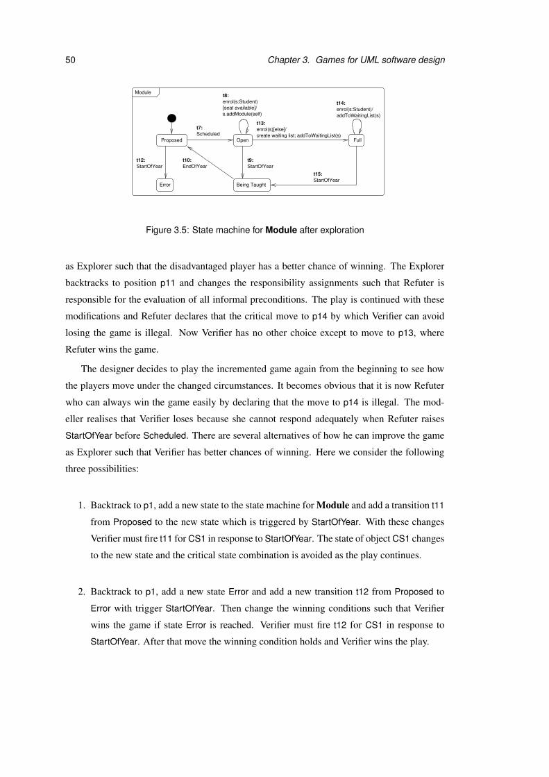
50 Chapter 3. Games for UML software design
Error
Full
t8:Module
enrol(s:Student)
ProposedScheduled
EndOfYear StartOfYear
t7:
t9:t10:
Open
Being Taught
StartOfYear
s.addModule(self)
StartOfYear
enrol(s:Student)/[seat available]/
create waiting list; addToWaitingList(s)
t12:
t13:
t14:
t15:
enrol(s)[else]/
addToWaitingList(s)
Figure 3.5: State machine for Module after exploration
as Explorer such that the disadvantaged player has a better chance of winning. The Explorer
backtracks to position p11 and changes the responsibility assignments such that Refuter is
responsible for the evaluation of all informal preconditions. The play is continued with these
modifications and Refuter declares that the critical move to p14 by which Verifier can avoid
losing the game is illegal. Now Verifier has no other choice except to move to p13, where
Refuter wins the game.
The designer decides to play the incremented game again from the beginning to see how
the players move under the changed circumstances. It becomes obvious that it is now Refuter
who can always win the game easily by declaring that the move to p14 is illegal. The mod-
eller realises that Verifier loses because she cannot respond adequately when Refuter raises
StartOfYear before Scheduled. There are several alternatives of how he can improve the game
as Explorer such that Verifier has better chances of winning. Here we consider the following
three possibilities:
1. Backtrack to p1, add a new state to the state machine for Module and add a transition t11
from Proposed to the new state which is triggered by StartOfYear. With these changes
Verifier must fire t11 for CS1 in response to StartOfYear. The state of object CS1 changes
to the new state and the critical state combination is avoided as the play continues.
2. Backtrack to p1, add a new state Error and add a new transition t12 from Proposed to
Error with trigger StartOfYear. Then change the winning conditions such that Verifier
wins the game if state Error is reached. Verifier must fire t12 for CS1 in response to
StartOfYear. After that move the winning condition holds and Verifier wins the play.

3.2. Exploration games 51
3. Backtrack to p7 and change the winning conditions such that Verifier wins if Refuter
challenges with Scheduled immediately after StartOfYear. With these changes position
p7 becomes a winning position for Verifier, because the two events have been generated
in the forbidden order.
The first two options indirectly extend the set of moves for Verifier in the arena of the game.
If the first solution is chosen, Verifier has the chance to circumvent a position which leads to
a win for Refuter in the old game by using one of the new moves. The last two possibilities
involve changes of the winning conditions such that Refuter is discouraged to make the critical
sequence of moves which causes problems for Verifier. Here we assume that the Explorer
chooses the second alternative. If played without further exploration, the improved game is
always won by Verifier.
We can continue in various ways, with the designer gradually improving both the system
design and its specification. A way of incrementing the game which has not been considered
yet is to alter the guard conditions at transitions. For example, the designer can refine the
conditions under which t8 may be fired by adding a guard condition seat available. When
Refuter challenges by Scheduled and m.enrol from the initial position, Verifier now loses the
play if Refuter declares that seat available does not hold. Verifier cannot find a transition that is
triggered by enrol in the state machine for Module and the game settings forbid her to discard
call events. That means there are no moves possible from the current position which belongs
to Verifier, and Refuter wins the play.
A simple way to improve Verifier’s chances of winning the game is to change the game set-
tings such that call events may be discarded. Another approach which preserves the strictness
of the game settings is to add more detail about what should happen if there is no seat available
when a student attempts to enrol to the model. One solution is to add the student to a waiting
list. In order to follow this approach the Explorer adds a new state Full, and transitions t13, t14
and t15 as shown in Figure 3.5 to the state machine diagram. After this exploration Verifier has
again a winning strategy for the current game.
3.2.4 Significance of explorations
Explorations can be regarded as possible answers to design questions. Sometimes very concrete
design questions arise during a play. For example, the fact that Verifier loses the game at
position p13 after the first incrementation leads to the following questions:
52 Chapter 3. Games for UML software design
• What should happen if the year starts before the module is scheduled?
• Is the sequence StartOfYear, Scheduled legal or out of the system’s scope?
Often it may be enough that the play evolves in a way which was not expected by the
designer to make him think about certain design issues. For example, the designer may realise
during a play that a feature which he assumed to be part of the system is missing both in the
specification and the design. The designer discovers this flaw because he misses corresponding
moves in the play. In our example the designer could for instance ask himself whether a module
can be cancelled at any time.
In other cases the idea for a new exploration is not triggered directly by a play, but comes up
when the designer thinks about how to improve the game for one of the players. For example,
attaching a guard condition to t8 is just one possibility to improve the chances of Refuter that
the designer decided to follow.
It is also possible to think of Explorer’s incrementations as independent proposals for sys-
tem changes which are not inspired by plays of the exploration game at all. On this more
general level exploration games can be used to explore the evolvability of a system. In this
case the incrementation is hypothetical and serves to show that a game can be extended as
desired without breaking functionality that was present in the initial design.
3.3 Tool support for exploration games
The game concepts introduced in this thesis are aimed at improving tool support for UML
design. In this section we describe the desired functionality of a game-based UML design tool.
First of all the tool should help the designer to set up the game, preferably in a comfortable
way which does not require knowledge about formal games. During a play the tool will always
have a notion of the “current game”. It should be able to manage the evolution of the game and
record important information such as the play history.
The main purpose of the tool is to let the user play the current game. Thereby the tool could
operate in different modes. The simplest possibility is that the tool merely ensures that the game
is played correctly and declares the winner. In this mode the user chooses the moves for Refuter
and Verifier, and explores the game by incrementations. The designer may also choose to fulfil
the tasks of the Referee, if he does wants not want the tool to take on this role. In fact there
might be several users which share these responsibilities between them. For example, Refuter
and Verifier could be played by different users who “discuss” and improve the design, and yet
3.3. Tool support for exploration games 53
another user might act as Referee. This mode of the tool is probably particularly useful in early
design phases where more detail needs to be added to the game before it becomes interesting
and challenging to play with less involvement of the user(s).
Another operation mode for the tool would be to play the role of Verifier or Refuter. The
user chooses which of these parts he wants to play and the tool takes the opponent’s part. If it
is possible for the tool to calculate a winning strategy for the current game, then the tool might
play this winning strategy. Otherwise, the tool might use random choices or heuristics to play
as well as possible. If incompleteness of the design model prevents the tool from computing a
completely safe winning strategy, it will have to adapt its strategy during the play.
Alternatively, the tool could also attempt to take on the parts of both players. If the game
is detailed enough for full verification, the tool plays completely on its own. The designer
observes the moves of the tool, acts as Referee and interrupts if he wants to increment the
game. If the game definition is not precise enough, the designer may be asked by the tool to
provide additional information during a play. For example, if the target position of a move is
not clearly specified, the designer must define it manually.

Chapter 4
Exploration game framework
Exploration games have been introduced informally with an example in the last chapter. With
the aim of preparing and simplifying the implementation of a tool which is based on exploration
games we have also developed a more formal definition. Since exploration games are intended
to be applicable to different combinations of UML diagrams, their general definition is given
in the form of a framework. The details that are left open in the framework have to be filled by
its instantiations.
UML behavioural model elements can be guarded by preconditions and may have parame-
ters. For example, UML state machine transitions can be guarded by a condition and triggered
by a parameterised event. First we transfer these notions to our framework by introducing
moves with parameters and preconditions. Then we define the necessary steps for making a
move in an exploration game. The responsibilities for performing these steps can be distributed
flexibly among the game participants by responsibility sets.
An exploration game can be played in strict mode without incremental steps, like a verifi-
cation game. Informally defined preconditions and decisions by the Referee cause uncertainty
which has to be taken into account for the definition of strategies and winning strategies. Ex-
ploration games can also be played in exploration mode, where the Explorer may increment
the game definition during a play. This chapter is concluded with a description of how arenas
and winning strategies are computed for exploration games and which restrictions are required
for their computation.
55

56 Chapter 4. Exploration game framework
4.1 Parameters and preconditions
In this section we transfer the concepts of parameterisation and preconditions as used in UML
to our exploration game framework. As usual the arena of an exploration game consists of a set
of positions P and a set of moves M. In order to introduce parameterised moves to the game,
we first define parameter sets, signatures and assignments.
Definition 4.1.1 (Parameter Set, Signature and Assignment) A parameter set X = {x1 :
T1, . . . ,xn : Tn} consists of parameter names xi and types Ti. A parameter signature is a list
Y = [x1 : T1, . . . ,xn : Tn] of disjoint parameter names and types. A parameter assignment γ over
X is a function [x1 7→ t1, . . . ,xn 7→ tn] with ti ∈ Ti ∪⊥Ti which maps all parameters xi to values
of the appropriate type. The set of all parameter assignments over X is denoted by ΓX .
In an exploration game, each move has a parameter signature and assignment. The signa-
ture defines which parameters are required when the move is made and the assignment provides
values for each of them. Parameter signatures were chosen here instead of sets because they
specify an order of the parameters. The notion of a parameter assignment is the same for pa-
rameter signatures and sets, including the possibility of leaving values undefined. Moreover, a
move has a name, which indicates the effect of a move, and a precondition. In the context of
UML, the move name often corresponds to the name of a dynamic model element such as, for
example, an operation or event name. A precondition defines restrictions that may depend on
the play history, on the internal structure of the current position, or on the values of parameters
that are in scope at the source position.We do not specify how exactly a precondition is defined,
but assume that it is either a boolean condition or an informal expression in natural language.
Notice that we do not require the preconditions at moves emerging from the same position to
be mutually exclusive.
Definition 4.1.2 (Moves) A move m consists of a source position p, a target position q, a
parameter signature Ym, a parameter assignment γm ∈ ΓYm , a precondition prem, and a name
label νm. The set Mp,q contains all moves with source position p and target position q.
A position has a parameter set and assignment which record the parameters that are in scope
together with their current values. The parameters at positions are mainly used for storing all
inputs that are made by the game participants during a play. They can also serve as global
variables for storing additional information which should be available during a complete play
and is not recorded in the positions’ internal structure.

4.2. Move steps 57
Definition 4.1.3 (Positions) A position p has a parameter set Xp = {x1 : T1, . . .xn : Tn} and a
variable assignment γp ∈ ΓXp .
We leave it open to the concrete instantiation of the framework for how long each param-
eter remains in scope during a play and how nested parameter scopes are treated. The only
requirement on positions is that every parameter must have a provenance within the arena.
Each parameter at a position p must be in scope at all immediately preceding positions, or it
has to be added by all moves leading to p. An interesting situation arises if both conditions hold
at the same time. A concrete game variant has to specify whether the value that was present at
the source position or the value provided during the move should be used at the target position.
For the example instantiations presented in this thesis we always give priority to the parameters
of moves. We assume that the parameter assignment which is provided for the move overwrites
the values for parameters that have been in scope at the source position.
Definition 4.1.4 (Exploration Game Arena) An exploration game is played in an exploration
game arena with moves and positions as defined above in Definition 4.1.2 and Definition 4.1.3.
For all positions q and parameters xi : Ti ∈ Xq at least one of the following conditions must
hold:
1. xi is a parameter of all moves m ∈ Mp,q and γq(xi) = γm(xi), or
2. xi ∈ Xp for all positions p which are connected to q by a move m ∈ Mp,q.
Notation: In graphic representations of an exploration game arena the moves are labelled by
their name, parameter assignment in round brackets and precondition in square brackets. The
parameter signature is normally not included in the figures. The positions have the current pa-
rameter assignment attached in curly brackets. An arena excerpt A2, which is used as example
for this chapter, is shown in Figure 4.1.
4.2 Move steps
During a play the preconditions at moves first have to be evaluated in order to determine which
moves are legal from the current position before the next move is made. We assume that there
exists an evaluation function which is defined on the basis of the play history. A formally
defined precondition may only refer to parameters which are in scope at the source position
of the move. That means parameters provided during one move can only be used reasonably

58 Chapter 4. Exploration game framework
............
p0:R
[x1==true] [x1==true]
m3(−6)m3(−7)[x1==true]m3(18)m3(17)m3(−8)
m2m2
m1(true) m1(false)
{x1=true} {x1=false}
m1(true)
{x1=true} {x1=false} p2:R p3:V p4:V
p5:R p6:V p7:R p8:V p9:R
{x2=−7} {x2=17}
m1(false)
[x1==true]
m4
p1:R
m4
{x2=18}{x2=−8} {x2=−6}
[x1==true]
m0[isLegal?]
Figure 4.1: Arena excerpt A2
during subsequent moves. Thereby the concepts of invocation (during which the parameter
values are provided) and evaluation/execution (during which the parameters are used) is cleanly
separated into two moves. Alternatives to this solution will be discussed in Chapter 7.
If a precondition refers to parameters which are not in scope, its evaluation is undefined.
Moreover the evaluation can be undefined because the precondition is too imprecise, or because
details about the play history or current position are missing. Imprecise preconditions will
occur frequently if we use constraints in UML diagrams for their definition, because UML does
not require constraints to be specified formally and permits definitions in natural language. The
resolution of undefined precondition evaluation is performed by the game participant who is
responsible for this task during a play. Formally the declaration of which moves are treated as
legal corresponds to an extension or completion of the evaluation function.
Definition 4.2.1 (Precondition Evaluation) Let π be a play prefix ending in position p and
[[ ]]π an evaluation function such that [[prem]]π ∈ {true, f alse,⊥} for all m ∈ Mp,q. The evalua-
tion function is extended to [[ ]]′π such that for all moves m ∈ Mp,q
1. [[prem]]′π ∈ {true, f alse} and
2. [[prem]]′π = [[prem]]π iff [[prem]]π 6= ⊥.
The extended evaluation function [[ ]]′π is used to evaluate all preconditions emerging from p.
Definition 4.2.2 (Legal Move) Let π be a play prefix ending in p and [[ ]]′π an extended evalu-
ation function. A move m is a legal move from p iff [[prem]]′π = true.
4.2. Move steps 59
p0,m1(x1:Boolean)
............
p0:R
{x2=−8} {x2=−6} {x2=18}
[x1==true] [x1==true]
m3(−6)m3(−7)[x1==true]m3(18)m3(17)m3(−8)
m2m2
m1(true) m1(false)
{x1=true} {x1=false}
m1(true)
{x1=true} {x1=false} p2:R p3:V p4:V
p5:R p6:V p7:R p8:V p9:R
{x2=−7} {x2=17}
m4 m4
m1(false)
[x1==true] [x1=true]p3, m3(x2:Integer)
[x1==true]
p4,m3(x2:Integer)
[x1==true]p1:R
m0[isLegal?]
Figure 4.2: Partition of A2 into move shapes
Once it has been determined which moves are legal from the current position, one of the
game participants decides which kind of move should be made by choosing a move shape.
The idea behind this is that the game participants choose the direction in which they want to
proceed with the game. A move shape is a set of moves which are almost identical. They may
only differ in their parameter assignments or target positions. Figure 4.2 shows how some of
the moves in the example arena excerpt A2 are partitioned into move shapes. Each move shape
is labelled by those parts of its elements which coincide: the source position, move name,
parameter signature and precondition.
Definition 4.2.3 (Move Shape) A move shape [m] is an equivalence class which is induced by
an equivalence relation ∼S on M where m is a representative of [m]. Two moves are related by
∼S iff they have the same source position, name, precondition and parameter signature. The
quotient set of all move shapes in a game arena is denoted by S . The subset of S which contains
all move shapes from position p is called Sp.
At a position p the evaluation function yields the same result for all elements of a move
shape, because the precondition, play history and current parameter values at p are always the
same. Hence the legality of all moves in a move shape can be determined by evaluating the
precondition at one representative m ∈ [m]. If the representative move is legal, the move shape
itself and all of its elements are legal.
Lemma 4.2.4 Let π be a play prefix ending in p and m ∈ Mp,q. All moves x ∈ [m] are legal
moves from p iff m is a legal move from p.
60 Chapter 4. Exploration game framework
Definition 4.2.5 (Legal Move Shape) A move shape [m]∈ Sp whose elements are legal moves
from p is called a legal move shape.
The next stages of choosing a move consist of providing a suitable parameter assignment
and resolving non-determinism. Both of these steps reduce the original set of moves given
by the move shape further and specify a subset of it. The final step is only necessary if the
parameter assignment has not reduced the choice to a single move yet. For the moves shown in
Figure 4.2 this is the case if the move shape labelled by p0, m1(x1:Boolean) is selected. There
is still a choice to be made, because there are two moves each for m1(true) and m1(false) which
are completely identical except for their target positions.
Definition 4.2.6 (Four-stage Move) Making a move from position p consists of the following
four steps:
1. Precondition evaluation. Extension of the evaluation function such that informally de-
fined preconditions at moves from p can be evaluated.
2. Choice of move shape. Selection of a legal move shape [m] ∈ Sp.
3. Parameter provision. Provision of a suitable parameter assignment γm for [m] which
yields a set [m]γm ⊆ [m] containing all moves with the same parameter assignment γm.
4. Resolution of non-determinism. Selection of a move m ∈ [m]γm if | [m]γm |> 1.
Notice that moves in traditional two-player verification games as introduced in Section 2.4.3,
p.25, are not split into different stages. Instead all tasks that are necessary for making a move
are performed by the player who owns the current position. Our main reason for splitting
a move into several parts is to allow either player or the Referee to perform these steps as
explained in Section 4.3.
4.3 Responsibility sets
So far we have not defined which steps of a move are performed by which game participant.
In this section we introduce responsibility sets to assign these responsibilities to one of the
players or the Referee for particular sets of positions or move shapes. Since a move involves
four steps, a responsibility set consists of four sets for each player which specify their range
of responsibility. For all positions or move shapes where a task is not fulfilled by either of the
players the Referee takes on this responsibility.

4.3. Responsibility sets 61
Definition 4.3.1 (Responsibility set) A responsibility set contains two sets B σ,C σ of posi-
tions, and two sets Dσ,Eσ of move shapes for each player. The sets for Player σ must be
disjoint from the counterparts for Player σ. They define the responsibilities of the players for a
play prefix π ending in position p and move shape [m] ∈ S as follows:
1. If p ∈ Bσ then Player σ extends the evaluation function [[ ]]π and decides which move
shapes are legal from p.
2. If p ∈ C σ then Player σ chooses the next legal move shape [m].
3. If [m] ∈ Dσ then Player σ assigns parameters to [m].
4. If [m] ∈ Eσ then Player σ resolves non-determinism for [m].
5. The Referee fulfils all responsibilities which are not assigned to either of the players.
Parts 1 to 4 of the definition correspond directly to the four stages of a move. The responsi-
bility for a task can be assigned completely to one of the players. For example, Player σ can
choose all move shapes if C σ = P. The general definition of a responsibility set permits many
interesting variations. For instance, Dσ can be defined such that Player σ provides parameters
for all moves with a particular name.
In general Player σ has the best chances of winning the game if all responsibilities defined
by the responsibility set are exclusively assigned to her. On the other hand, the worst combina-
tion for Player σ is the one where Player σ is in charge at all positions and for all move shapes.
If the Referee makes one of the decisions during a move, the outcome is uncertain and he may
decide in favour of either of the players.
However, the importance of the settings depends on the concrete game. Even if “more
power” is in general better for Player σ, it does not mean that it is always useful in practice.
Consider, for instance, a game where all moves of Player σ are determined, i.e. from each
position p ∈ Pσ emerges at most one move. For this game it does not increase Player σ’s
chances of winning if she is allowed to choose move shapes from Player σ’s positions. Thus
a modification of the responsibility set does not always make the game easier for a player. It
is also not possible to make a general statement about the relationship between the responsi-
bilities. Whether the setting for one responsibility is more important than another one depends
on the concrete game definition. However, extending the responsibilities for player Player σ at
least never has a negative effect on the Player σ’s chances of winning. In Section 4.5 we will

62 Chapter 4. Exploration game framework
state a lemma which expresses under which conditions incrementations of the responsibility
set preserve a winning strategy for Player σ.
Using the extensions which have been proposed so far in this chapter we can now give a
formal definition of exploration games:
Definition 4.3.2 (Exploration Game) An exploration game G = (A, p0,W 0,R) is given by an
exploration game arena A, an initial position p0, a winning set W 0 for Player 0, and a respon-
sibility set R.
A concrete instantiation of the exploration game framework must specify how exactly the
winning set is defined. As for verification games, which have been introduced in Section 2.4.3,
p.25, this is usually done indirectly by defining winning conditions for the players. In the
example given in Chapter 3 all plays during which particular state configurations are reached
have been declared as winning plays for Refuter. These plays constitute a winning set W 1 for
Refuter. Since we do not allow draws, Verifier wins all other plays, i.e. the winning set for the
game is given by all plays which are not in W 1.
In this thesis we only consider exploration games whose winning conditions fall into the
Borel hierarchy as described in Chapter 2. As mentioned earlier this includes all conditions
expressing reachability, safety or liveness. Furthermore preorder and equivalence games, such
as, for instance, bisimulation games, which are used for the comparison of processes, have
simple Borel winning conditions. We expect this to be sufficient for the kinds of games that we
are interested in.
4.4 Plays in strict mode
During a play in strict mode the game definition remains unchanged. The two players and the
Referee fulfil their responsibilities according to the responsibility set and the Explorer merely
observes the play. A play in strict mode is similar to a play of an ordinary verification game,
but involves some degree of uncertainty caused by precondition evaluation and the Referee’s
decisions.
Definition 4.4.1 (Play in Strict Mode) Let G = (A, p0,W 0,R) be an exploration game. A play
of G in strict mode is a sequence of positions p0 p1 . . . such that pi+1 ∈ succ(pi) for all play
prefixes π = p0 . . . pi. For a finite play of length n either succ(pn) = /0 or [[prem]]′π = f alse for
all m ∈ Mpn,q. At each position pi the players and the Referee perform a four-stage move as
4.4. Plays in strict mode 63
described in Definition 4.2.6. Thereby they fulfil the different tasks according to responsibility
set R. A play in strict mode is won by Player 0 if it is in W 0, or by Player 1 otherwise.
By our definition of a four-stage move the players and the Referee are only allowed to pick
legal move shapes. Therefore all moves which are made during a play are legal.
Lemma 4.4.2 Let p0 p1 . . . be a play in strict mode of an exploration game G. By Defini-
tion 4.2.5 and Definition 4.2.6 all moves in the play are legal, i.e [[prem]]′π = true for all play
prefixes π = p0 . . . pi and moves m ∈ Mpi,pi+1 .
The players can not only win by choosing “clever” move shapes, but also by making use
of the other responsibilities that are assigned to them according to responsibility set R. Thus
it does not make sense anymore to speak of a strategy as a single function. Instead we define
a strategy for Player σ as a combination of four functions b,c,d and e, which use the sets
given in R as part of their domain. Function c, for example, maps all play prefixes ending
in a position at which Player σ is responsible for choosing the next move shape to a move
shape. The remaining three functions define how Player σ fulfils the tasks specified by the
other responsibilities in a similar way.
Definition 4.4.3 (Strategy) A strategy ψ = (b,c,d,e) for Player σ in an exploration game G
is given by the following four partial functions, where S is the set of move shapes in the arena
and π = p0 . . . pn a play prefix:
1. b : P∗Bσ → (S → {true, f alse}) which maps play prefixes to a function with
dom(b(π)) = Spn that assigns truth values to move shapes.
2. c : P∗C σ → S which maps play prefixes to move shapes.
3. d : P∗ ×Dσ → ΓM which provides parameter assignments for play prefixes and move
shapes, such that d(π, [m]) ∈ ΓXm .
4. e : P∗×Eσ → P (M) which determines a set of moves for play prefixes and move shapes
such that e(π, [m]) ⊆ [m] and each pair of moves in e(π, [m]) differs in their parameter
assignments or target positions.
The domain of b and c are all play prefixes ending in a position of B σ or C σ, respectively. For
d and e the domains contain all tuples (π, [m]) where π ends in p and [m] ∈ Sp.

64 Chapter 4. Exploration game framework
When a player applies a strategy in a game, the different parts of the strategy determine
how the play is continued. For instance, if player σ must choose the next move shape, function
c in a strategy for σ is defined at the current position and tells Player σ which move shape she
should select. A play conforms to a strategy ψ when it coincides with the functions of ψ at all
positions and move shapes that are in ψ’s domain.
Definition 4.4.4 (Strategy Conformance) A prefix π = p0 . . . pn of a play in strict mode con-
forms to a strategy ψ = (b,c,d,e) for Player σ if the following conditions hold for all
πi = p0, . . . pi and moves m ∈ Mpi,pi+1 with 0 ≤ i < n:
1. [[prem]]′πi= b(πi)([m]) if pi ∈ Bσ and [[prem]]πi = ⊥,
2. m ∈ c(πi) if pi ∈ C σ
3. γm = d(πi, [m]) if [m] ∈ Dσ, and
4. m ∈ e(πi, [m]) if [m] ∈ Eσ.
A play conforms to ψ if all its play prefixes conform to it.
Definition 4.4.5 (Winning Strategy) A strategy ψ = (b,c,d,e) for Player σ in an exploration
game G is a winning strategy if all plays of G in strict mode that conform to it are won by
Player σ.
Notice that the four functions that constitute a strategy for Player σ have to “work together” for
all situations. A winning strategy must always be successful, even in the worst case. Because
the game is competitive, it is sure that Player σ will try to force Player σ to make moves such
that she eventually loses the play. Even though the Referee is neutral, it may happen that he
always makes decisions that are disadvantageous for Player σ, and the winning strategy must
nevertheless guarantee that Player σ wins. Furthermore the strategy must ensure that the moves
which are induced by it are legal. The legality of a move often depends on the the decisions
about informal preconditions and parameter assignments which are made during a play. In
order to be completely safe a strategy for Player σ has to be independent of the Referee’s and
σ’s decisions. This is a very strict requirement which may sometimes be difficult to fulfil.
There are games for which no safe winning strategy exists for either player, even though
we only consider Borel winning conditions here. This loss of determinacy is caused by the
unpredictability of the Referee. However, if all decisions in the game are made by the players,
the game is determined and one of the players has a winning strategy.
4.5. Plays in exploration mode 65
It is also possible to define an unsafe winning strategy which involves some speculation
about decisions of the opponent and the Referee. Since the two players may make different
assumptions about the the play, they can both have an unsafe winning strategy for the same
game. For the definition of an unsafe winning strategy we have to clarify the notion of a
“possibly legal play” first.
Definition 4.4.6 (Possibly Legal Play) Let π = p0 . . . pn be a play prefix. If there exists a move
m ∈ Mpi,pi+1 for each πi = p0 . . . pi with 0 ≤ i ≤ n such that [[prem]]πi 6= false then πi is called a
possibly legal play prefix. A play is possibly legal if each of its prefixes is possibly legal.
Definition 4.4.7 (Unsafe Winning Strategy) A strategy ψ for Player σ in an exploration
game G is an unsafe winning strategy if each play which conforms to ψ is possibly legal and
won by Player σ.
An unsafe winning strategy exploits and relies on the uncertainty in the game. The Referee
may sometimes decide in favour of Player σ, while there is no chance that Player σ will ever do
this voluntarily. However, Player σ may sometimes be forced to act in benefit of Player σ. If
a player uses an unsafe winning strategy he may at some point reach a position where moving
according to his strategy would be illegal. Since this is forbidden in an exploration game, he
must divert from the strategy and choose another move which is legal. He may for instance de-
cide to continue the play according to another unsafe winning strategy which involves different
assumptions.
4.5 Plays in exploration mode
The other mode which an exploration game can be played in is called exploration mode. In this
mode the game definition is incremented during a play by the Explorer. An incrementation may
affect all parts of the game except for the initial position. The initial position is fixed because
otherwise the play would become invalid immediately. In the context of UML the Explorer
often performs incrementations indirectly. In the example presented in Section 3.2.3, p.49,
some of the incrementations corresponded to changes in the state machine diagram. Usually
the Explorer will change only one part of the game at a time, but we do not forbid incrementa-
tions that affect several components at once. However, even if just one part is changed by the
Explorer, this may have side-effects on other components of the game.
66 Chapter 4. Exploration game framework
For example, an incrementation of the arena can involve changes of the positions as well
as of the moves. If the Explorer removes a position, all moves leading to or emerging from it
also have to be deleted – otherwise the arena would not be valid. The deletion may also have
an effect on the responsibility set whose components must always be subsets of the currently
existing positions and move shapes. If moves are added to the arena, the Explorer has to
specify a name, parameter signature, assignment and precondition for it. The Explorer may also
increment the arena by changing these features, such as, for instance, by making a precondition
more precise. If new positions or move shapes have been added, the responsibility set has to
be modified such that it takes the additional elements in the arena into account. In this chapter
we assume that the Referee will fulfil the different tasks at all new positions and moves. Notice
that an incrementation of a game based on UML will rarely focus on a single move at one time.
Instead the Explorer is likely to modify move shapes via changes in the UML diagrams.
Definition 4.5.1 (Incrementation) An incrementation is a tuple (G,G′) of two game defini-
tions G = (A, p0,W 0,R) and G′ = (A′, p0,W ′0,R′) with the same initial position p0.
Before we define a play in exploration mode during which the game may be changed,
we discuss the relationship between a game and its incrementation with respect to winning
strategies. Under some conditions a winning strategy for the old game can also be used in the
incremented game. We examine these circumstances more concretely on an incrementation
(G,G′) as defined above and assume that Player σ has a winning strategy ψ for G. Thereby it
is irrelevant whether ψ is a safe or unsafe winning strategy if not otherwise stated.
First we consider the case where the Explorer increments only the winning set of the
game. Usually this is done indirectly by modification of the winning conditions for the players.
Player σ can still use his winning strategy if he wins at least the same plays as before in G.
Notice that a change of the winning set for Player 0 always affects the winning set for Player 1,
too, because draws are not permitted.
Lemma 4.5.2 Let A = A′ and R = R′, but W 0 6= W ′0. If ψ is a winning strategy for Player 0
and W 0 ⊆W ′0 then ψ is a winning strategy for Player 0 in G′. In the case that ψ is a winning
strategy for Player 1 and W ′0 ⊆W 0, ψ is still a winning strategy for Player 1 in G′.
Let us now assume that the Explorer increments G by modifying the responsibility set and
leaves the other parts unchanged. After this incrementation ψ is a winning strategy for Player σ
in G′ if σ has at least the same responsibilities and Player σ at most the same as in G.
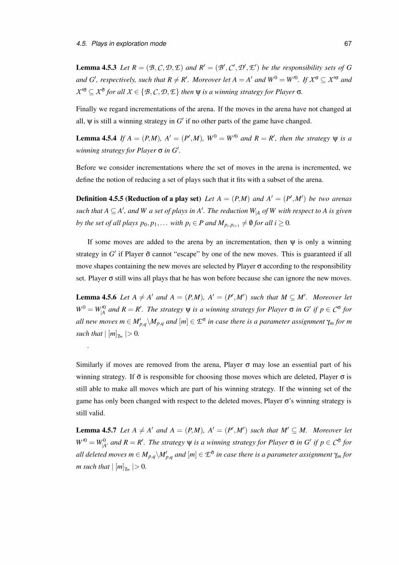
4.5. Plays in exploration mode 67
Lemma 4.5.3 Let R = (B,C ,D,E) and R′ = (B ′,C ′,D ′,E ′) be the responsibility sets of G
and G′, respectively, such that R 6= R′. Moreover let A = A′ and W 0 = W ′0. If X σ ⊆ X ′σ and
X ′σ ⊆ X σ for all X ∈ {B,C ,D,E} then ψ is a winning strategy for Player σ.
Finally we regard incrementations of the arena. If the moves in the arena have not changed at
all, ψ is still a winning strategy in G′ if no other parts of the game have changed.
Lemma 4.5.4 If A = (P,M), A′ = (P′,M), W 0 = W ′0 and R = R′, then the strategy ψ is a
winning strategy for Player σ in G′.
Before we consider incrementations where the set of moves in the arena is incremented, we
define the notion of reducing a set of plays such that it fits with a subset of the arena.
Definition 4.5.5 (Reduction of a play set) Let A = (P,M) and A′ = (P′,M′) be two arenas
such that A ⊆ A′, and W a set of plays in A′. The reduction W|A of W with respect to A is given
by the set of all plays p0, p1, . . . with pi ∈ P and Mpi,pi+1 6= /0 for all i ≥ 0.
If some moves are added to the arena by an incrementation, then ψ is only a winning
strategy in G′ if Player σ cannot “escape” by one of the new moves. This is guaranteed if all
move shapes containing the new moves are selected by Player σ according to the responsibility
set. Player σ still wins all plays that he has won before because she can ignore the new moves.
Lemma 4.5.6 Let A 6= A′ and A = (P,M), A′ = (P′,M′) such that M ⊆ M′. Moreover let
W 0 = W ′0|A and R = R′. The strategy ψ is a winning strategy for Player σ in G′ if p ∈ C σ for
all new moves m ∈ M′p,q\Mp,q and [m] ∈ Eσ in case there is a parameter assignment γm for m
such that | [m]γm |> 0.
.
Similarly if moves are removed from the arena, Player σ may lose an essential part of his
winning strategy. If σ is responsible for choosing those moves which are deleted, Player σ is
still able to make all moves which are part of his winning strategy. If the winning set of the
game has only been changed with respect to the deleted moves, Player σ’s winning strategy is
still valid.
Lemma 4.5.7 Let A 6= A′ and A = (P,M), A′ = (P′,M′) such that M′ ⊆ M. Moreover let
W ′0 = W 0|A′ and R = R′. The strategy ψ is a winning strategy for Player σ in G′ if p ∈ C σ for
all deleted moves m ∈ Mp,q\M′p,q and [m] ∈ E σ in case there is a parameter assignment γm for
m such that | [m]γm |> 0.

68 Chapter 4. Exploration game framework
Another condition which ensures that Player σ can reuse his winning strategy is that the pre-
conditions at new or deleted moves are evaluated to false for all possible plays. That means
these moves are irrelevant for the game and their addition or removal does not affect Player σ’s
winning strategy. We do not consider this case formally here.
If the preconditions at moves have been changed the conditions under which an old winning
strategy works for the new game definition depend on whether the strategy is safe or unsafe. If
ψ is a safe winning strategy and Player σ can still make all moves that are relevant for applying
ψ, he can use ψ to win the incremented game. In the case that ψ is an unsafe winning strategy
it is enough to require that all plays which conform to ψ are possibly legal to preserve this
property.
Lemma 4.5.8 Let A 6= A′ and A = (P,M), A′ = (P,M′) such that M and M′ only differ in the
preconditions at moves. Moreover let W 0 = W ′0 and R = R′. If ψ is a safe winning strategy
and all plays π which are legal in G are also legal plays in G′, then ψ is a safe strategy for
Player σ in G′. If ψ is unsafe and all plays π which are possibly legal in G are also possibly
legal plays in G′, then ψ is an unsafe strategy for Player σ in G′.
There are two ways in which a play in exploration mode can proceed. Either the players
move normally, like in strict mode, or the Explorer increments the game definition. If he does
this, the play is continued according to the new version of the game.
Definition 4.5.9 (Play in Exploration Mode) A play in exploration mode of an exploration
game G0 is a sequence of exploration positions (p0,G0)(p1,G1) . . . where each pi is a position
and Gi = (Ai, p0,W 0i ,Ri) a game definition with Ai = (Pi,Mi). For all (pi,Gi) the following two
conditions must hold for all i ≥ 0:
1. (pi, pi+1) ∈ Mi or pi = pi+1, and
2. (Gi,Gi+1) is an incrementation or Gi = Gi+1.
The sequence (p0,G0)(p1,G1) . . . is also called an exploration of G0. An exploration is won
by Player 0 if π = p0 . . . pi is a play in strict mode in arena Ai and an element of W 0i . If π is a
play in Ai which is not in W 0i , it is won by Player 1.
A special way of incrementing the arena of a game during a play is to change the current
position. Thereby the target position of the last move in the play history is modified in the
arena. This enables the Explorer to refine or correct the consequences of the last move. If the

4.5. Plays in exploration mode 69
current position is changed, the last element of the play history contains the new position and
modified game definition with the incremented arena.
Definition 4.5.10 (Change of Position) Let (p0,G0) . . .(pi,Gi) be a prefix of a play in explo-
ration mode. The Explorer may change the current position pi to a position pi+1 of his choice.
The move from pi−1 to pi is deleted from the arena, and a new move from pi−1 to pi+1 is added
to it. The play is continued at (pi+1,Gi+1), where Gi+1 is the game definition with the incre-
mented arena. The play history consists of (p0,G0) . . .(pi−1,Gi−1)(pi+1,Gi+1) after a change
of position.
The Explorer may also backtrack in the play history while the game is played. Notice that
backtracking refers both to the position and to the definition of the game. During a play the
Explorer can combine backtracking with game incrementations, which allows him to modify
the game at any position in the play history. This becomes important if the players do not move
as expected and the Explorer wants to examine whether an incrementation at an earlier point
leads to different behaviour of the players. It is also a means for restoring a former state of the
play if one of the players wins the exploration unexpectedly.
Definition 4.5.11 (Backtracking) Let (p0,G0) . . .(pn,Gn) be a prefix of a play in exploration
mode. Backtracking means that the Explorer selects an exploration position (pi,Gi) with
0 ≤ i < n. The play is then continued at (pi,Gi) and the new play history is (p0,G0) . . .(pi,Gi).
There is no general definition of when a play in exploration mode ends. In theory the
Explorer can continue to backtrack to an earlier position or increment the game forever. We
assume that the Explorer, played by the human designer, stops the exploration when the game
contains enough detail about the design and specification of the system under consideration.
Some of the Explorer’s incrementations can cause inconsistencies in the play history. The
play history becomes invalid when the Explorer deletes a move that has been used earlier in
the play or one of the positions that occur in the play history. Explorations like this are not
forbidden, but it should be realised by the designer that the current play cannot be repeated in
the incremented game.
70 Chapter 4. Exploration game framework
Definition 4.5.12 (Invalid play history) Let π = (p0,G0) . . .(pn,Gn) be a prefix of a play in
exploration mode. The history of π is invalid if it contains
1. a position pi such that pi is not a position in Gn, or
2. a move (pi, p j) which does not exist or is illegal at p0 . . . pi in Gn
with 0 ≤ i < n. A play has an invalid history if one of its prefixes has an invalid history.
4.6 Computation of the arena and winning strategies
Our definition of exploration games allows infinite sets of positions, moves and parameter as-
signments. Under these circumstances the arena is infinite which makes the computation of
winning strategies and development of tool support difficult. Here we formulate some restric-
tions which allow dynamic creation of the arena and computation of winning strategies. These
concepts have been used in the prototypical tool which is described in Chapter 6.
We assume that the set of move shapes in a game is finite and that there is a finite set of
parameter assignments for each parameter signature. Thereby we ensure that there exists only
a finite number of moves emerging from each position which restricts the arena in its width. A
method nextMoves can be defined as illustrated by the pseudocode in Figure 4.3. This method
is invoked whenever a new position is reached during a play. It yields all moves that emerge
from the new position and extends the arena dynamically. At an early design stage, where the
main concern of the designer is to add more detail to the game, this procedure is sufficient for
exploration.
As soon as the designer expects the tool to play the part of one of the players, computation
of winning strategies becomes important to make the tool a worthy opponent. Therefore the
depth of the arena has to be limited. Its unfolding is stopped when a fixed maximum depth n
is reached. With this restriction a finite subgraph of the arena can be searched depth-first from
the initial position for a winning strategy. The search terminates if a winning strategy has been
found or the arena has been built up to depth n without success. In the latter case the search
could be repeated with a greater value for n, but there is still no guarantee that this will yield a
winning strategy.
The solution that we follow here is to restrict the length of a play to n and define explicitly
who wins if the maximum length is reached. That means one of the players has a move limit for
winning the game. This approach can lead to winning strategies that are not very helpful for
4.6. Computation of the arena and winning strategies 71
public Set nextMoves(Position p) {
if (p has been visited) {
return moves emerging from p in arena
} else {
define set result as empty set
compute set of move shapes with p as source position
for each move shape ms emerging from p {
compute set of possible parameter assignments for ms
for each possible parameter assignment pa {
create move m by assigning pa to ms
add m to result
add target position of m to arena
}
}
add all moves in result to arena
return result
}
}
Figure 4.3: Pseudocode for method nextMoves
the analysis of the system. For example, the tool may yield a winning strategy which involves
going round in circles until the move limit is reached for the player who wins in this case.
This can be prevented by making the winning conditions more precise such that a player who
exhausts the move limit by undesired move sequences loses the play.
Alternatively the algorithm for computing winning strategies could try to find “meaningful”
strategies and exclude trivial solutions. Another possibility for handling plays of length n would
be to regard them as draws. The disadvantage of this approach is that the winning conditions
of the restricted game are not Borel conditions anymore. Even if the Referee does not fulfil any
of the responsibilities in the game, none of the players may have a winning strategy.
An algorithm for the computation of winning strategies must dynamically build up the
arena and evaluate the winning conditions at the same time. We assume that there exists a
function which evaluates the winning conditions over a play to true or false, and a function [[ ]]π
for the evaluation of preconditions as described in Section 4.1, which is completed by the game
participants during a play in the first move step of each move, if necessary.
A winning strategy for Player σ is created by trying out which decisions during a play lead
to a win for Player σ. Thereby the responsibilities of the players and the Referee have to be
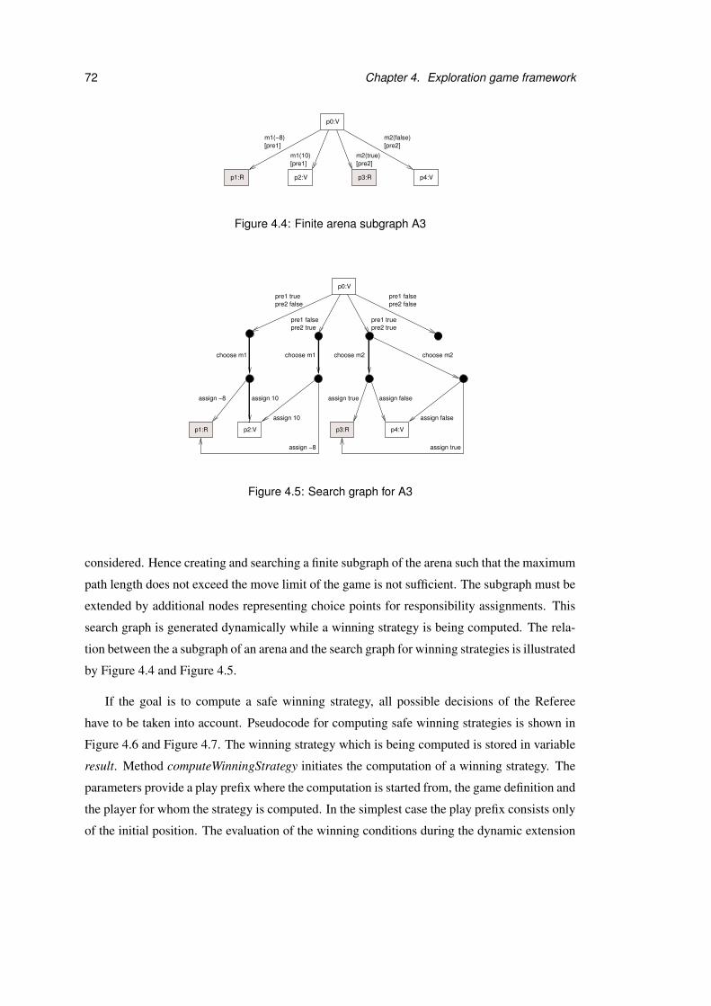
72 Chapter 4. Exploration game framework
p1:R p2:V p3:R p4:V
p0:V
[pre2]m2(true)
[pre1]m1(10)
[pre1]m1(−8)
[pre2]m2(false)
Figure 4.4: Finite arena subgraph A3
p1:R p2:V p3:R p4:V
p0:V
pre2 true
pre2 falsepre1 false
pre1 truepre1 falsepre2 true
pre2 falsepre1 true
choose m1
assign −8 assign 10
assign −8
assign true assign false
assign true
choose m1 choose m2
assign 10 assign false
choose m2
Figure 4.5: Search graph for A3
considered. Hence creating and searching a finite subgraph of the arena such that the maximum
path length does not exceed the move limit of the game is not sufficient. The subgraph must be
extended by additional nodes representing choice points for responsibility assignments. This
search graph is generated dynamically while a winning strategy is being computed. The rela-
tion between the a subgraph of an arena and the search graph for winning strategies is illustrated
by Figure 4.4 and Figure 4.5.
If the goal is to compute a safe winning strategy, all possible decisions of the Referee
have to be taken into account. Pseudocode for computing safe winning strategies is shown in
Figure 4.6 and Figure 4.7. The winning strategy which is being computed is stored in variable
result. Method computeWinningStrategy initiates the computation of a winning strategy. The
parameters provide a play prefix where the computation is started from, the game definition and
the player for whom the strategy is computed. In the simplest case the play prefix consists only
of the initial position. The evaluation of the winning conditions during the dynamic extension

4.6. Computation of the arena and winning strategies 73
WinningStrategy result = empty winning strategy
WinningStrategy computeWinningStrategy(Play prefix, Game g, String player)
if wsExtension(play, player) is true return result, otherwise return null
}
boolean wsExtension(Play prefix, String player) {
evaluate the winning conditions for prefix
if (outcome of the play is clear or play is finished) {
return true if player wins, false otherwise
} else {
Set nextMoves = nextMoves(last position in prefix)
return wsExtensionStep(nextMoves, prefix, player)
}
}
Figure 4.6: Pseudocode for computation of safe winning strategies – Part 1
of the search tree is performed within method wsExtension. If the outcome of a play is not yet
known, the possible next moves are computed by method nextMoves, which has been discussed
earlier.
The actual computation of the winning strategy and unfolding of the search graph happens
in the recursive method wsExtensionStep, which is shown in Figure 4.7. Depending on which
player is responsible for performing a move step, one or all possible continuations of the play
have to be considered. If a winning strategy is found during this process, it is stored in result,
and the method returns true.
The complexity of this algorithm is linear in the size of the graph on which the search for
the strategy is performed. In the worst case the search graph is built up completely, all nodes
are visited once, and no winning strategy is found. The size of the search graph depends on
several factors, such as the move limit for the game, the number of moves that emerge from
each position, the number of possible parameter assignments for each type and the number of
non-deterministic moves from each position. Furthermore the function for the evaluation of
preconditions influences the size of the graph. If this function is defined for a particular move
shape, its result has to be used during the play. That reduces the permitted truth assignments
for each first move step in a play.

74 Chapter 4. Exploration game framework
boolean wsExtensionStep(Set nextMoves, Play prefix, String player) {
Set possibilities = all possibilities of performing the next move step
if (desired winner is responsible for the next move step) {
for each x in possibilities {
Set reducedMoves = moves in nextMoves that are possible after move step x
if (cardinality of reducedMoves is 1) {
add the only move in reducedMoves to prefix
boolean wsexists = wsExtension(prefix, player)
} else {
boolean wsexists = wsExtensionStep(reducedMoves, prefix, player)
}
restore version of prefix before wsExtensionStep was called the last time
if (wsexists) {
add decision for x at current position to result
return true
}
}
} else {
for each x in possibilities {
Set reducedMoves = moves in nextMoves that are possible after move step x
if (cardinality of reducedMoves is 1) {
add the only move in reducedMoves to prefix
boolean wsexists = wsExtension(prefix, player)
} else {
boolean wsexists = wsExtensionStep(reducedMoves, prefix, player)
}
restore version of prefix before wsExtensionStep was called the last time
if (not wsexists) {
return false
}
}
// loop has been completed without returning false
return true
}
return false
}
Figure 4.7: Pseudocode for computation of safe winning strategies – Part 2

4.6. Computation of the arena and winning strategies 75
In case of an unsafe winning strategy speculations about the Referee’s behaviour can be
made, but the strategy is only successful if these assumptions prove to be true during a play.
That means the algorithm may yield a winning strategy that is only sometimes successful. If the
Referee makes a decision at a choice point, not all, but only one path from this choice point has
to lead to a win for the player for whom the strategy is computed. For details about the com-
putation of safe and unsafe winning strategies in the GUIDE tool refer to the documentation of
class DefaultStrategyBuilder.

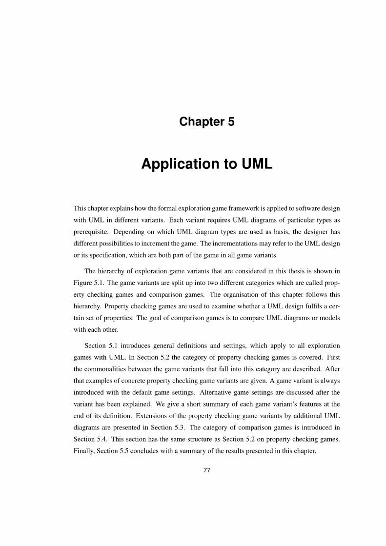
Chapter 5
Application to UML
This chapter explains how the formal exploration game framework is applied to software design
with UML in different variants. Each variant requires UML diagrams of particular types as
prerequisite. Depending on which UML diagram types are used as basis, the designer has
different possibilities to increment the game. The incrementations may refer to the UML design
or its specification, which are both part of the game in all game variants.
The hierarchy of exploration game variants that are considered in this thesis is shown in
Figure 5.1. The game variants are split up into two different categories which are called prop-
erty checking games and comparison games. The organisation of this chapter follows this
hierarchy. Property checking games are used to examine whether a UML design fulfils a cer-
tain set of properties. The goal of comparison games is to compare UML diagrams or models
with each other.
Section 5.1 introduces general definitions and settings, which apply to all exploration
games with UML. In Section 5.2 the category of property checking games is covered. First
the commonalities between the game variants that fall into this category are described. After
that examples of concrete property checking game variants are given. A game variant is always
introduced with the default game settings. Alternative game settings are discussed after the
variant has been explained. We give a short summary of each game variant’s features at the
end of its definition. Extensions of the property checking game variants by additional UML
diagrams are presented in Section 5.3. The category of comparison games is introduced in
Section 5.4. This section has the same structure as Section 5.2 on property checking games.
Finally, Section 5.5 concludes with a summary of the results presented in this chapter.
77
78 Chapter 5. Application to UML
Exploration games with UML
Property checking games
Variant A Variant CVariant B Variant D Variant E
property checking gamesExtensions of
Variant F
Comparison games
Figure 5.1: Hierarchy of exploration game variants
Notation The descriptions of the concrete game variants make frequent use of examples to
illustrate the definitions and settings. The symbol of a magnifying glass , which has been
taken from [Ico], indicates that a paragraph describes an example. The example paragraphs
also have wider margins on both sides. Verifier’s positions are labelled by “V” and shown as
rectangles which are mainly white but contain grey headings. Refuter’s positions are predomi-
nantly grey with white headings and labelled by “R”. The UML terms in this chapter are shown
in emphasised font, like InvocationAction, if they do not correspond to general object-oriented
concepts, as for example classes or states. In UML state machines the names of triggers that
represent the reception of a signal start with a capital letter as already introduced in Chapter 2.
5.1 General definitions and settings for all variants
This section contains general definitions and game settings for all game variants. The winning
conditions and responsibilities can both be defined by referring to the position ownership. The
game settings provide means to “tune” a game and may influence the game definition. The
modification of game settings is introduced as a new way for the Explorer to participate in a
play. The remaining Explorer moves have already been discussed in Chapter 4 and are briefly
summarised here.
5.1.1 All variants: Winning conditions
In the formal framework, which has been presented in Chapter 4, the winning set for Verifier is
part of the game definition. It contains all finite and infinite plays which are won by Verifier. All
remaining plays are won by Refuter. This definition ensures that the winning sets for Verifier
and Refuter have two important properties. First, all possible plays are covered and thus draws
5.1. General definitions and settings for all variants 79
are avoided. Second, there is no overlap between the sets of winning plays for the two players.
We require that all exploration games have winning sets with these properties.
So far we have not discussed how exactly the winning set for Verifier is specified via win-
ning conditions for the two players. Winning conditions may refer to different parts of the play
history and identify which plays belong to which winning sets. The purpose of the winning
conditions is to determine winning sets that have the two properties mentioned above. Thereby
it does not matter if the winning set for Verifier is defined directly, via the winning set for
Refuter, or by combinations thereof.
A winning condition belongs either to Verifier or Refuter and consists of boolean conditions
which can be connected by logic operators AND, OR and NOT. There are various possibilities
for specifying boolean conditions which can be combined with each other. For instance, one
condition could refer to the last position of the play and another one to the order of moves. If a
play fulfils the winning condition for a player, it is included in the player’s winning set.
A tool that is based on exploration games should ensure that a play is terminated as soon as
its outcome is known. Thus the winning conditions are evaluated after each move. Evaluating
the winning conditions corresponds to checking whether the current play prefix is enough to
decide who wins the play. If so, it is irrelevant how the play is continued – the play will always
be in the winning set for the same player and it is not worthwhile to continue the play.
Additionally a move limit can be specified to restrict the maximum length of a play (see
game settings for all variants, p.82). The condition
move limit reached
may be used within a winning condition for one of the players to identify all plays which have
reached the move limit. All plays which exceed the maximum length belong to the winning set
for the player whose winning condition contains this condition. The move limit applies to this
player’s opponent, who must demonstrate that he can win the play without exceeding the limit.
If there are winning conditions given for both players, it must be assured that all plays are
covered. This can be done by adding the condition
remaining plays
as disjunct to the winning condition for one of the players. Thereby it is determined who wins
a play if no other disjunct in the two winning conditions holds. This condition cannot be used
for the evaluation of play prefixes to terminate a play early as described above and should only
80 Chapter 5. Application to UML
be considered when the play has finished. In the remainder of this chapter we will always just
specify the winning condition for one player and assume that his opponent wins all other plays.
Most of the possibilities for defining a winning condition are discussed in the context of
concrete game variants, because they refer to variant-specific parts and semantics of positions
and moves. There is also a general condition
dead end position of opponent reached
which can form a part of the winning condition for a player in all game variants. It identifies
all finite plays which end in a position that belongs to the player’s opponent. This kind of
condition is used very frequently in classic verification games and is usually combined with
other reachability conditions.
5.1.2 All variants: Responsibilities
The formal framework presented in Chapter 4 allows the assignment of responsibilities to Veri-
fier and Refuter. However, sometimes it is easier to specify which responsibilities are not taken
on by one of the players. Therefore we also allow explicit assignment of the responsibilities
to the Referee. The four responsibilities considered here are evaluation of informally defined
preconditions, choice of the next move shape, provision of parameter values and resolution of
non-determinism. The responsibilities for Verifier, Refuter and the Referee must not overlap.
In the context of concrete game variants responsibilities are assigned to sets of positions
and moves which are identified by their variant-specific properties. A more general alternative
is to define the responsibilities with respect to position ownership. This possibility is used for
specifying the default responsibilities and is applicable to all game variants.
The list below shows the options for assigning each of the four tasks such that the re-
quirements of no overlaps and complete coverage are fulfilled. For parameter provision and
resolution of non-determinism the set of positions given by the options below is used to iden-
tify a set of moves. The game participant for whom the responsibility is defined has to fulfil
this task for all moves which have one of the given positions as source position. For exam-
ple, if Verifier is responsible for providing parameter values at her own positions, she provides
parameters for all moves that emerge from her positions.
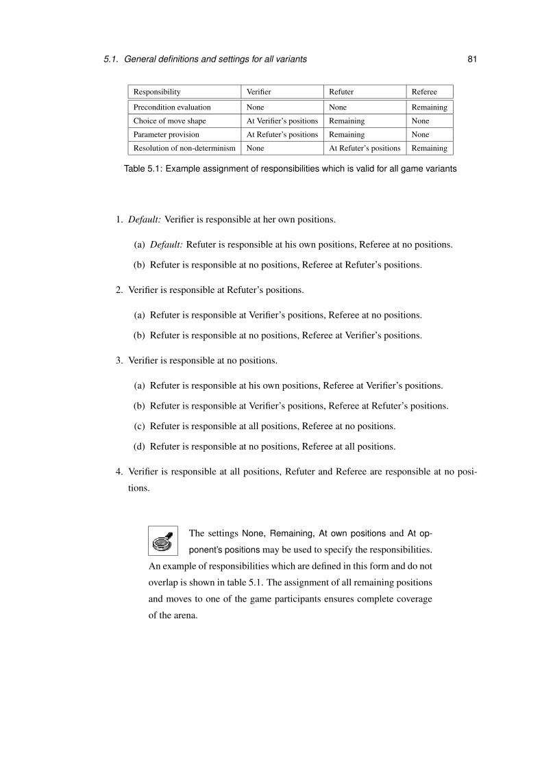
5.1. General definitions and settings for all variants 81
Responsibility Verifier Refuter Referee
Precondition evaluation None None Remaining
Choice of move shape At Verifier’s positions Remaining None
Parameter provision At Refuter’s positions Remaining None
Resolution of non-determinism None At Refuter’s positions Remaining
Table 5.1: Example assignment of responsibilities which is valid for all game variants
1. Default: Verifier is responsible at her own positions.
(a) Default: Refuter is responsible at his own positions, Referee at no positions.
(b) Refuter is responsible at no positions, Referee at Refuter’s positions.
2. Verifier is responsible at Refuter’s positions.
(a) Refuter is responsible at Verifier’s positions, Referee at no positions.
(b) Refuter is responsible at no positions, Referee at Verifier’s positions.
3. Verifier is responsible at no positions.
(a) Refuter is responsible at his own positions, Referee at Verifier’s positions.
(b) Refuter is responsible at Verifier’s positions, Referee at Refuter’s positions.
(c) Refuter is responsible at all positions, Referee at no positions.
(d) Refuter is responsible at no positions, Referee at all positions.
4. Verifier is responsible at all positions, Refuter and Referee are responsible at no posi-
tions.
The settings None, Remaining, At own positions and At op-
ponent’s positions may be used to specify the responsibilities.
An example of responsibilities which are defined in this form and do not
overlap is shown in table 5.1. The assignment of all remaining positions
and moves to one of the game participants ensures complete coverage
of the arena.
82 Chapter 5. Application to UML
5.1.3 All variants: Game settings
In this section settings concerning the definition of the game’s initial position, the play history,
move limits and the undefinedness of positions or the winning conditions are described. Three
different kinds of settings called upfront, play and incremental settings are distinguished in this
thesis. The abbreviations (U), (P) and (I) after the setting’s name are used to indicate the kind
of the setting.
Upfront settings determine how the game is set up on the basis of the UML model and
which information must be added by the designer. Play settings have an effect on how the
game is played and how a play is interpreted, but do not affect the game definition. If a game
setting is incremental, its modification results in a change of the game definition. Most of the
game settings introduced in this thesis are incremental settings which affect the arena of the
game in various ways.
Initial position (U) The initial position is the starting point for playing a game and computing
winning strategies. It can be defined on the basis of the UML model or manually by the
designer. The manual definition of the initial position allows more flexibility and is particularly
important with respect to the parameter set. Parameters are only added to positions during a
move or by the Explorer when he changes the current position. If there are parameters which
should be present during the complete play, independently of which moves and incrementations
are being made, then they should be added manually to the initial position. As usual these
parameters may occur in preconditions and can be used by moves. During a play the values of
these parameters may be modified by the Explorer if he changes the position.
1. Default: The initial position is given by the UML model as described for the concrete
game variants.
2. All parts of the initial position are manually specified by the designer when the game is
set up.
Play history (P) If the Explorer increments the game during a play, the play history may
become invalid. For example, moves that have been made earlier may not be possible anymore
or the positions of the game are defined differently in the incremented game. The default
setting, where an invalid play history is permitted, is particularly useful for games at early
design stages where the Explorer performs many incrementations. Once the design model has
become more stable, this setting can be used to forbid invalid play histories.

5.1. General definitions and settings for all variants 83
1. Default: The play history may be invalid.
2. The play history must be valid. The Explorer is not allowed to make any incrementations
which destroy the validity of the history.
The setting merely restricts the ways in which the Explorer can increment the game and
does not affect the game definition.
Undefined position parts (P) In some of the game variants that are introduced later, the
target position of a move may not be completely defined. If the undefined parts of a position are
irrelevant during the rest of the game, this is not a problem. However, the missing information
can be added to the game during a play, if desired. This setting is particularly important if more
detail is needed to determine the next possible moves and their target positions.
1. Default: The positions may contain undefined parts.
2. Some explicitly specified parts of the position may be undefined. All other parts have to
be completed by the Explorer via a change of the current position when a new position
is reached.
3. Positions with undefined parts are not allowed. The Explorer must complete the infor-
mation when a new position is reached. The Explorer is forced to change the current
position to a more precise position at this point.
This setting can force the Explorer to increment the game in certain situations. It does not
correspond directly to an incrementation but enforces certain incrementations during a play.
Move limit (I) The move limit defines the maximal number of moves of which a play may
consist. This number refers only to the moves by Verifier, Refuter and the Referee. It does not
include incrementations by the Explorer.
1. Default: None.
2. A natural number greater than zero.
The move limit becomes important if the game is played against a tool because it enforces
finiteness of the arena and enables the computation of winning strategies by the simple algo-
rithm which has been introduced in this thesis (see Section 4.6, p.70). A play is never continued

84 Chapter 5. Application to UML
after the move limit has been reached. At this point one of the players must be declared as the
winner. The move limit is a “hidden part” of the winning conditions, because its value has an
influence on which plays are in the winning sets of the players.
Undefined evaluation of the winning conditions (I) If the positions in the current play pre-
fix contain undefined parts or the winning conditions are not formulated precisely enough, it
may not be possible to evaluate whether one of the players has won during a play. Notice that
enforcing a change of the current position by the Explorer at the point where the evaluation
of the winning conditions is undefined does not necessarily solve this problem. The winning
conditions may refer to the complete play history and not only to its last position.
1. Default: If the play is finished because there are no further moves possible or the move
limit has been reached, the Referee decides who wins the play. Otherwise the evaluation
of the winning conditions with respect to the current play prefix is ignored and the play
is continued.
2. The Referee decides whether any of the winning conditions is fulfilled or not.
This setting has an influence on which plays of a game are won by which player. It deter-
mines what should happen to plays and play prefixes if it cannot be decided whose winning
set they belong to. Hence this setting is incremental with respect to the winning sets for the
players.
5.1.4 All variants: Explorer moves
In an exploration game the Explorer can move in one of the following ways:
• Increment the game definition by changing the winning conditions, responsibilities or
current position. The Explorer may change all aspects of the position, including its set
of parameters and parameter assignment. The new position becomes the target position
of the move which has previously been made. Hence a change of the current position
corresponds to an incrementation of the arena.
• Change any of the incremental or play settings of the game. If the modified setting is an
incremental setting, the change corresponds to an incrementation of the game definition.
Upfront settings may not be changed by the Explorer.
5.2. Property checking games 85
• Backtrack to an earlier position in the play history. The game definition and settings
which have been active at the position where the Explorer backtracks to become active
again.
5.2 Property checking games
In this section game variants whose winning conditions express desired or undesired properties
of the design are introduced. All game variants which are described in this section are based on
a collection of objects. The object collection represents the part of the system that is examined
by the game and is essential for the definition of the positions.
5.2.1 Property checking games: Winning conditions
OCL is a syntactically powerful language for specifying static properties of objects and classes.
This makes it a reasonable candidate for specifying the winning conditions of property check-
ing games. The drawbacks of OCL are that it is fairly complex and that software designers are
often not very familiar with it. Furthermore OCL is only useful for expressing static properties.
Instead of OCL we use simple “patterns” for the specification of the winning conditions.
The same approach can also be found in the prototypical tool which is presented in Chapter 6.
We introduce these patterns informally and give examples of how they would be translated into
OCL where appropriate.
There are two approaches to limiting the challenges that Refuter may make. First, chang-
ing the winning conditions such that Verifier wins more plays means that Refuter has less
possibilities to move without losing. If Refuter plays rationally, he will always try to avoid
moves which lead to a win for Verifier. Another solution is to remove some of Refuter’s moves
from the arena. This can be achieved by taking other UML diagram types into account and is
introduced in Section 5.3, p.143.
5.2.2 Property checking games: Incrementations
We do not expect the collection of objects to be fixed during the game and allow the Explorer
to modify it. Thus the Explorer can increment the game as follows for all property checking
game variants:

86 Chapter 5. Application to UML
• Remove an object from the object collection.
• Add an object to the object collection.
Notice that the addition of an object may lead to positions with undefined parts in the arena,
because the Explorer merely adds a new object identifier to the collection. The state and proper-
ties of the new object are unknown after this incrementation. However, the Explorer can move
by changing the current position to add more information about the new object immediately
after he has added it.
In theory the Explorer can increment the game infinitely by adding more and more objects.
As long as the Explorer is played by the human designer, we expect him to stop at a reasonable
limit which still allows observation of the different objects. If the tool was supposed to act
as Explorer, which is out of the scope of this thesis, it would be necessary to introduce game
settings which restrict the permitted number of objects.
5.2.3 Variant A: State machines
A game which is based on state machines has been introduced as informal example in Sec-
tion 3.2.1, p.45. Here we make the definition of this game variant more precise and consider
how more advanced features of UML state machines fit into the game framework.
5.2.3.1 Variant A: Prerequisites
As before the game is based on a collection of objects, a class diagram, and a set of state
machines with class context. The state machine for a class specifies the possible state config-
urations for all objects which are instances of this class. Such configurations, which are based
on state machines, are called abstract state configurations in this thesis. If the behaviour of an
object in the object collection is not specified by a state machine, the object is assumed to be in
a default state, which does not change during the game. Objects like this are “placeholders” and
may be used as values for parameters of this type. The designer may associate an object with
certain properties and can use this knowledge during a play, even though the object’s behaviour
is not modelled.

5.2. Property checking games 87
Location Person0..*1 0..*
0..*
startWork(e:Employer)stopWork(e:Employer)
CS_Student Employer
removeEmployee(p:Person)addEmployee(p:Person)
matriculate()
Figure 5.2: Example class diagram for variant A
As example for this game variant we consider a class diagram
with four classes CS Student, Employer, Location and Per-
son as shown in Figure 5.2. The object collection for this game consists
of Joe:CS Student, PubX:Employer and Italy:Location. The state ma-
chines for CS Student and and Employer are shown in Figure 5.3 and
Figure 5.4. The transitions and history states are labelled to allow easy
reference.
The state machine for CS Student models the life of a Computer Sci-
ence student who works on practicals and a project in each year of his
studies. The student’s progress with the two parts of the course is cap-
tured by the two concurrent regions of state Studying. When the student
is not studying, he can work or go on holiday if he has saved enough
money. After each break from studying he continues his studies where
he has stopped, which is modelled by the history states.
When the deadlines for the last practical and project are over, the student
has completed his degree or matriculates for the new academic year. An
employer can either have not enough or enough staff. In both cases
employees can be added or removed from the employer. Notice that
the state machine for Employer is non-deterministic because it is for
instance unspecified whether transition t24 or t26 should be taken from
the default state in response to event addEmployee. There exist no state
machines for classes Person or Location. Hence object Italy will always
be in the default state.

88 Chapter 5. Application to UML
H*
����
Studying
Project
h1:
h2:
Project completed
t1:
t2:
CS_Student
e.removeEmployee(self)
[l in the mountains]/ski
[enough savings] [no savings]
[else]/matriculate;pay fees
[degree completed]
t3:
t14:
t13:
t11:t10:
t9:
t8:t7:
t6:
t15:
t16:
startWork(e:Employer)/e.addEmployee(self)
t17: t19:
t18:
t21:
t23:
t22:
t20:
On Holiday
t12:
Documentation Implementation
DesignAnalysis
Practical1 Practicals completedPractical2
At Work
H
stopWork(e:Employer)/
Work/self.savings++
TravelTo(l:Location)
[l on the sea]/swim
TravelTo(l:Location)
Deadline project
Deadline p1
t4:
Deadline p2
t5:
Figure 5.3: State machine for CS Student in variant A
5.2.3.2 Variant A: Positions
A position of the game always contains an abstract state configuration and an event pool for
each object. Refuter owns the positions where all event pools are empty. All other positions
belong to Verifier. For objects whose state machine contains regions with history pseudostates
(see [UML03b, p.470]), the position must additionally record parts of the object’s history. This
is done by a history mapping which maps each history pseudostate to a state configuration.
The history mapping yields the state configuration which should become active when the re-
gion containing the history pseudostate is entered the next time. In accordance with the UML
semantics the mapping only preserves the topmost substate in case of a shallow history pseu-
dostate and points to the default states further down in the state hierarchy. For a deep history
pseudostate the mapping returns the complete last state configuration.
The initial position of the game is given by the default state configuration and empty event
pool for all objects in the object collection, and the parameter set is empty. For those objects

5.2. Property checking games 89
Employer
addEmployee(p:Person)
addEmployee(p:Person)
Not enough staff Enough staff
t26:
t27:t24:
t29:removeEmployee(p:Person)
removeEmployee(p:Person)t28:
removeEmployee(p:Person)t25:
addEmployee(p:Person)/p.Work
Figure 5.4: State machine for Employer in variant A
where the history is recorded, the history mapping is defined by the default transition emerging
from the history state. This transition specifies which state should be entered in case the region
containing the history pseudostate has not been active before. The history mapping yields the
state configuration consisting of this state and the default states of its subvertices1.
The initial position for our example is shown in Figure 5.5.
The default state configuration is obtained by determining the
default states top-down in the state hierarchy. The transition from the
initial pseudostate in CS Student points to the fork pseudostate where
t1 and t2 emerge. Both of these transitions lead to states within Study-
ing. State Practical1 is the target of t1. It is the leaf of the state config-
uration’s left branch because it is not a composite state. In case of t2
the target state Project contains further states and the next level of the
state hierarchy has to be considered. Since Analysis is the default state
in Project and not a composite state, it becomes the leaf of the default
state configuration’s right branch. The subtrees whose root nodes are the
default states of Studying’s regions containing the history pseudostates
are recorded in Joe’s history mapping. For objects PubX and Italy the
definition of the default state configuration is easier because no state
hierarchies have to be considered.
1When a region is entered for the first time it does not matter whether its history pseudostate is shallow or deep.Since there is no history recorded yet the default states of the subvertices are used in both cases.
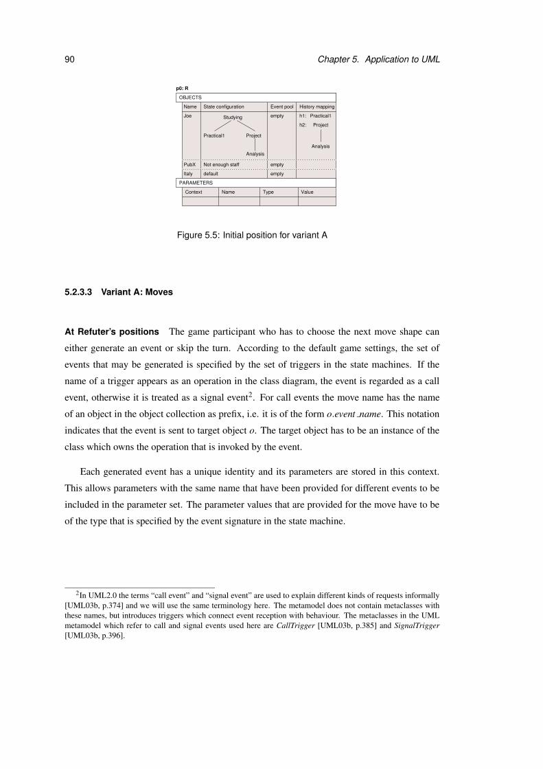
90 Chapter 5. Application to UML
default
Not enough staffPubX
Italy
State configuration
Studying
ProjectPractical1
Analysis
Event poolName
Joe
History mapping
h2:
h1: Practical1
Analysis
Project
empty
empty
empty
TypeName Value
p0: R
Context
OBJECTS
PARAMETERS
Figure 5.5: Initial position for variant A
5.2.3.3 Variant A: Moves
At Refuter’s positions The game participant who has to choose the next move shape can
either generate an event or skip the turn. According to the default game settings, the set of
events that may be generated is specified by the set of triggers in the state machines. If the
name of a trigger appears as an operation in the class diagram, the event is regarded as a call
event, otherwise it is treated as a signal event2. For call events the move name has the name
of an object in the object collection as prefix, i.e. it is of the form o.event name. This notation
indicates that the event is sent to target object o. The target object has to be an instance of the
class which owns the operation that is invoked by the event.
Each generated event has a unique identity and its parameters are stored in this context.
This allows parameters with the same name that have been provided for different events to be
included in the parameter set. The parameter values that are provided for the move have to be
of the type that is specified by the event signature in the state machine.
2In UML2.0 the terms “call event” and “signal event” are used to explain different kinds of requests informally[UML03b, p.374] and we will use the same terminology here. The metamodel does not contain metaclasses withthese names, but introduces triggers which connect event reception with behaviour. The metaclasses in the UMLmetamodel which refer to call and signal events used here are CallTrigger [UML03b, p.385] and SignalTrigger[UML03b, p.396].

5.2. Property checking games 91
In our example game PubX.removeEmployee is one of the call
events that may be generated. Since removeEmployee is an
operation of Employer, the event must be targeted at an Employer ob-
ject in the object collection such as PubX. An example of a signal event
in this game is Deadline p2. Since it does not occur in any of the classes
in the class diagram it is always broadcast to all objects.
The target position of a move corresponding to the generation of an event only differs from
the source position in its event pools and parameter sets. The generated event is added to
the event pool(s) of the target object(s). Its parameters are added to the target position with
the values that are provided during the move. The state configurations and history mappings
of all objects are always identical at the source and target positions for this kind of move.
Furthermore the precondition of a move that represents the generation of an event is always
true.
From positions where at least one event may be generated the turn may be skipped. In
this case a special event called skip is added to the event pools of all objects. The target
position is owned by Verifier because all event pools contain the skip event. The idea behind
the skip move is to allow the game participants to fire transitions with empty triggers from the
succeeding position. This will be discussed in more detail when moves at Verifier’s positions
are considered.
At Verifier’s Positions From Verifier’s positions the game participants move by firing transi-
tions in the state machines or discarding events. For each object in the object collection whose
event pool is not empty, an event is dispatched. According to the default game settings the event
pool is a queue and events are dispatched in the order they were put into the queue (also known
as “FIFO” = First-In-First-Out). A move must specify for each object how the dispatched event
should be handled. The precondition for each move is defined by the conjunction of precon-
ditions for each object. An object’s precondition expresses under which circumstances the
dispatched event may be handled in the way specified by the move. The parameters which are
associated with the dispatched event’s identity are removed from the parameter set during the
move and do not appear in the target position.
Following the UML semantics [UML03b, p.492] an event is discarded if it does not enable
a transition in the state machine of the target object. According to the UML specification a
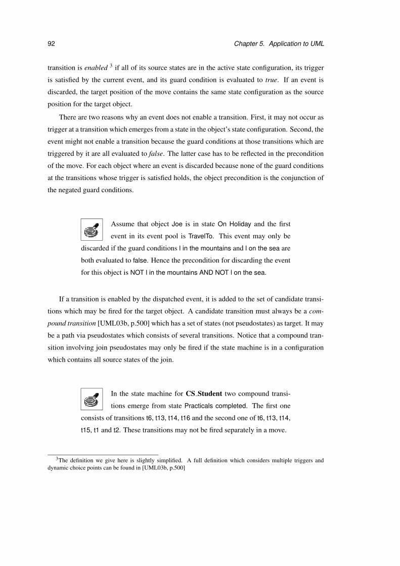
92 Chapter 5. Application to UML
transition is enabled 3 if all of its source states are in the active state configuration, its trigger
is satisfied by the current event, and its guard condition is evaluated to true. If an event is
discarded, the target position of the move contains the same state configuration as the source
position for the target object.
There are two reasons why an event does not enable a transition. First, it may not occur as
trigger at a transition which emerges from a state in the object’s state configuration. Second, the
event might not enable a transition because the guard conditions at those transitions which are
triggered by it are all evaluated to false. The latter case has to be reflected in the precondition
of the move. For each object where an event is discarded because none of the guard conditions
at the transitions whose trigger is satisfied holds, the object precondition is the conjunction of
the negated guard conditions.
Assume that object Joe is in state On Holiday and the first
event in its event pool is TravelTo. This event may only be
discarded if the guard conditions l in the mountains and l on the sea are
both evaluated to false. Hence the precondition for discarding the event
for this object is NOT l in the mountains AND NOT l on the sea.
If a transition is enabled by the dispatched event, it is added to the set of candidate transi-
tions which may be fired for the target object. A candidate transition must always be a com-
pound transition [UML03b, p.500] which has a set of states (not pseudostates) as target. It may
be a path via pseudostates which consists of several transitions. Notice that a compound tran-
sition involving join pseudostates may only be fired if the state machine is in a configuration
which contains all source states of the join.
In the state machine for CS Student two compound transi-
tions emerge from state Practicals completed. The first one
consists of transitions t6, t13, t14, t16 and the second one of t6, t13, t14,
t15, t1 and t2. These transitions may not be fired separately in a move.
3The definition we give here is slightly simplified. A full definition which considers multiple triggers anddynamic choice points can be found in [UML03b, p.500]
5.2. Property checking games 93
Instead one of the compound transitions must be selected and all transi-
tions which are part of it are fired. Since both compound transitions visit
the join pseudostate that merges transitions t6 and t13, they may only be
fired if the configuration of the state machine contains states Practicals
completed and Project completed.
A move consists of firing one of the candidate transitions for each object where the event
enables a transition. Each combination of candidate transitions is represented by a separate
move. The precondition for each object which performs a state transition is defined by the guard
condition at the transition that is fired. If a transition consists of several transition segments, the
conjunction of all guard conditions at the segments is used as precondition for this object. This
situation can arise when intermediate pseudostates are part of the transition path to the next
state. Each of the guard conditions is evaluated in the context of the object which performs a
transition and with the parameter values that have been provided for the dispatched event.
If a transition is fired for an object, the target position of the move contains the new state
configuration according to the UML semantics for the object. If a region containing a history
pseudostate is the target of a transition, the history mapping is used to determine the new
configuration. For fork pseudostates the targets of their outgoing transitions become part of
the next state configuration. Similarly the target of a join pseudostate’s outgoing transition
is used in the next state configuration if the join is the target of the transition. The remaining
pseudostate kinds entry, exit, terminate and choice are not considered for this game variant (see
PseudoState [UML03b, p.469] and Section 5.2.3.8, p.109). In case of a FinalState [UML03b,
p.462] the object is destroyed and removed from the object collection.
A move from Verifier’s position p1 to Refuter’s position p2
is shown in Figure 5.6. At position p1 the event Deadline
project with identity e1 must be dispatched for all objects, because it
is the only event in all event pools. The event satisfies the trigger at
transition t12 in the state machine for Joe at p1. During the move Joe’s
state configuration changes to Project completed, which is the target
state of the transition. For PubX and Italy the event is discarded because
it does not trigger a state machine transition.
If more than one transition is enabled in the same state machine, the transitions are in con-
flict. In order to resolve conflicts between enabled transitions UML specifies firing priorities
94 Chapter 5. Application to UML
Joe: fire t12PubX: discard e1Italy: discard e1
empty
empty
empty
Context
Context
Studying
Project completedPractical1
History mapping
PubX Not enough staff
Italy default
Italy
PubX
default
Not enough staff
Name State configuration
p2: R
Joe
Event pool
h2:
h1: Practical1
Project
Design
Type ValueName
Name
p1: V
State configuration Event pool History mapping
h2:
h1: Practical1
Project
Design
Name Type Value
Joe Studying
ProjectPractical1
Design
e1: Deadline project
e1: Deadline project
e1: Deadline project
OBJECTS
PARAMETERS
OBJECTS
PARAMETERS
Figure 5.6: Example move from Verifier’s position in variant A
[UML03b, p.493]. The default settings for this game variant define that UML’s rules for de-
termining firing priorities are ignored. All legal moves may be selected independently of the
priority of the transitions that are part of it.
Activities in state machines: Firing a transition for an object can result in the execution
of activities. Activities consist of actions and may be modelled by activity diagrams. In a
more general sense activities are “language-specific text strings used to describe a computa-
tion” [UML03b, p.378]. The language which the activity body is formulated in may be OCL,
natural language, or a programming language. In this thesis we expect activities to be modelled
by activity diagrams. Thus activities in state machines are treated as invocations of activity di-
agrams, if they exist. For variant C, which is presented in Section 5.2.5, p.133, both UML
state machines and activity diagrams are used as basis for the game. Here we only regard the
information in the state machines and abstract from the actual behaviour that takes place. We

5.2. Property checking games 95
assume that the behaviour is completed successfully and concentrate on the possible effects of
an invocation on the state machines during the run-to-completion step.
Each activity in a state machine is given by a textual activity expression. An activity ex-
pression consists of actions which are separated by semicolons. Here only actions which are
of the form [object expression.]activity name[(parameter list)] are considered. The parts in
square brackets are optional,. If an action does not respect this format, it is ignored.
An object expression must either be an object name from the object collection or a param-
eter with an object as value, otherwise it is ignored. We do not consider navigation along links
or invocation of operations in the object expression. The parameter list may consist of objects
from the object collection, primitive values such as a String or Integer values, and self, which
indicates that the object invoking the activity passes itself as parameter. If an element of the
list violates these requirements, the complete parameter list is ignored.
In UML terms the actions in an activity expression are InvocationActions [UML03b, p.206,
p.236]. Instances of all concrete subclasses of InvocationAction except for CallBehaviorAction
[UML03b, p.224] cause events which may enable state machine transitions. A CallBehav-
iorAction is an exception because it invokes a behaviour directly and thus does not have any
“side-effects” on the state machines. UML does not specify how the different kinds of Invoca-
tionActions should be distinguished in a textual activity expression. For this game variant we
ignore the special case of CallBehaviorActions. All InvocationActions are treated in the same
way and result in event generations.
The activities in a state machine and the corresponding event generations for all actions are
performed according to the order prescribed by UML: exit activities in the states of the source
state configuration, effects at the transition which is fired, and finally entry- and do-activities
in the states of the target state configuration. All activities that are caused by firing a set of
transitions are executed in the same move. Each event which is generated during the move
has the parameter values which are specified in the action’s parameter-list. It is put into the
target object’s event pool, if the action contains a valid object expression. Otherwise the event
is added to the event pools of all objects.
The default game settings for this variant specify that all activities are treated as asyn-
chronous invocations. That means the object which has requested the invocation can continue
immediately with its execution, completes the transition and changes its state. Thus a move
corresponds to a run-to-completion step in each of the state machines.
96 Chapter 5. Application to UML
Figure 5.7 shows an example of a move where a transition
which has an activity as effect is fired. At position p3 event
startWork with identity e2 is the only element in the event pool of Joe.
All other event pools are empty. The parameter set holds the value of
parameter e for event e2 which has been provided during the previous
move.
Event e2 is dispatched for Joe and satisfies transition t17 in the corre-
sponding state machine. The transition is fired and its effect performed.
The action in the activity expression specifies that activity addEmployee
is invoked. The object expression is e, which occurs as parameter for
the dispatched event in the parameter set and has the value PubX. The
parameter list contains self, which means that Joe is supplied as param-
eter. Thus a new event e3 with target PubX and Joe as parameter is
generated.
The state of Joe changes to At Work because the transition is completed
after the generation of the new event e3, which represents the invocation
of the activity. During the next move e3 must be dispatched and causes
either transition t24 or t26 to fire.
Transitions with empty triggers: A special situation arises if a skip event is dispatched
from the event pool, which indicates that the last move from one of Refuter’s positions was
skipped. The skip move can be answered by firing transitions which do not have a trigger
or discarding the skip event. Discarding the skip event for all objects amounts to answering
the skip move by another skip which leads back to the previous position. Notice that a skip
sequence always has to be initiated from Refuter’s positions. It is not possible to skip the move
from Verifier’s positions if the skip event is not present in the event pools.
This solution has been chosen because it fits well with the notion of position ownership in
this variant. Refuter owns all positions at which events are generated by the environment, while
all positions at which the system must react to the events that have occurred belong to Verifier.
If transitions with empty triggers could be fired at any time, i.e. independently of whether all
event pools are empty or not, it would be impossible to define the ownership of positions on
the basis of the event pools. Furthermore skip events ensure that a game participant cannot
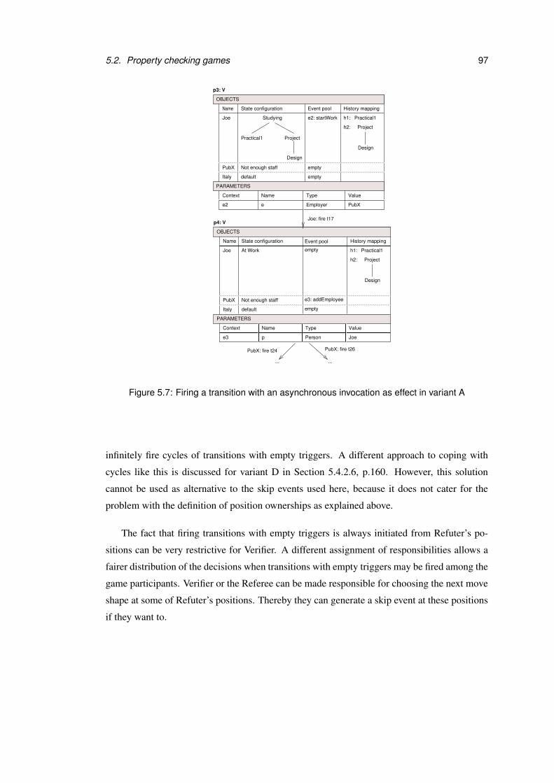
5.2. Property checking games 97
Context
Context
Italy
PubX
default
Not enough staff
empty
empty
e2 e Employer PubX
Joe: fire t17
PubX: fire t24
... ...
PubX: fire t26
Italy
PubX
default
Not enough staff
At Work
e3 p Person Joe
empty
e3: addEmployee
empty
ProjectPractical1
Design
Studying
State configuration Event pool
Joe
p3: V
History mapping
Name Type Value
Name State configuration
Joe
p4: V
History mapping
Name Type Value
h2:
h1: Practical1
Project
Design
h2:
h1: Practical1
Project
Design
Event pool
e2: startWork
OBJECTS
PARAMETERS
OBJECTS
PARAMETERS
Name
Figure 5.7: Firing a transition with an asynchronous invocation as effect in variant A
infinitely fire cycles of transitions with empty triggers. A different approach to coping with
cycles like this is discussed for variant D in Section 5.4.2.6, p.160. However, this solution
cannot be used as alternative to the skip events used here, because it does not cater for the
problem with the definition of position ownerships as explained above.
The fact that firing transitions with empty triggers is always initiated from Refuter’s po-
sitions can be very restrictive for Verifier. A different assignment of responsibilities allows a
fairer distribution of the decisions when transitions with empty triggers may be fired among the
game participants. Verifier or the Referee can be made responsible for choosing the next move
shape at some of Refuter’s positions. Thereby they can generate a skip event at these positions
if they want to.

98 Chapter 5. Application to UML
Figure 5.8 shows an example. At Refuter’s position p5 the
move is skipped and the skip event is put into all event pools.
At p6 the game participant who has to select the next move shape can
respond by a skip, which leads back to position p5. Alternatively the
skip event can be used to fire transition t23 for Joe and is discarded for
all other objects.
5.2.3.4 Variant A: Winning conditions
For the examples considered in this section we assume that the game is played with the default
game settings and default responsibility assignments.
State combinations A state combination identifies a set of positions in the arena. If a posi-
tion from this set is reached during a play, the player for whom the combination is defined wins.
In its simplest form the state combinations refer directly to the objects in the object collection.
In syntactically more powerful languages like OCL state combinations are often defined in the
context of a class or involve the usage of quantifiers.
An example of winning conditions with a simple syntax is
shown below. This pattern has been used for the prototypi-
cal implementation described in Chapter 6. All plays during which a
position where Joe is in state Practical2 and in Analysis or Design at
the same time are won by Refuter. Furthermore Refuter wins all plays
where a position with PubX in state Not enough staff and Joe in On
Holiday is visited.
Refuter
Joe IN Practical2 AND Joe IN Analysis OR
Joe IN Practical2 AND Joe IN Design OR
PubX IN Not enough staff AND Joe IN On Holiday
Refuter can easily win a game with this winning condition if he gener-
ates the event Deadline p1 at the initial position. Verifier has no other

5.2. Property checking games 99
Context
empty
empty
On Holiday
default
PubX
Italy
empty
skip skip
empty
emptyPubX
Italy default
empty
Not enough staff
default
PubX
Italy
Joe: fire t23
[no savings]
Event pool
Type
State configurationName
Joe
Event pool History mappingName
Joe
Name Type Value
State configuration
History mapping
Name Value
p5: R
Event pool
Value
State configuration
On Holiday
Name
Joe skip
skip
skip
Name Type
History mapping
p6: V
p7: R
Project
Studying
Practical2
Implementation
h2:
h1:
Project
Practical2
Implementation
h2:
h1:
Project
Practical2
Implementation
h2:
h1:
Project
Practical2
Implementation
OBJECTS
PARAMETERS
Not enough staff
OBJECTS
PARAMETERS
OBJECTS
PARAMETERS
Not enough staff
Context
Context
Figure 5.8: Skipping a move and firing a transition with an empty trigger in variant A
choice than to respond by a move to a position where Joe is in state
Practical 2 and Analysis, which is one of the illegal state combinations.
The first two state combinations in this specification can be captured by
an OCL class invariant for CS Student as shown below. The difference
is that the invariant must hold for all objects of class CS Student and
not only for object Joe.

100 Chapter 5. Application to UML
Class invariants express a desired property of the design and Refuter
wins a play if a class invariant is violated. Therefore the original state
combinations are negated in the invariant. It is not possible to lift the
third line of the winning condition above to class level and express it
by an OCL invariant because it refers to two objects of different classes
which are not connected with each other.
context CS_Student inv:
not(
self.oclIsInState(Practical2) and
self.oclIsInState(Analysis) or
self.oclIsInState(Practical2) and
self.oclIsInState(Design)
)
Event occurrences In this game variant the positions contain the event pools for each object.
The set of positions at which a player wins can be identified via the events in the pool. It is
often useful to combine statements about event occurrences with state combinations.
The condition for Refuter shown below is fulfilled by all po-
sitions where Work and stopWork are in the event pool of Joe
at the same time. In our example game such a situation can never arise
and hence the winning condition for Refuter never holds.
Refuter
Work IN Joe AND stopWork IN Joe
The following example expresses that Verifier wins if a position is
reached where Joe is in state Studying and stopWork is in its event
pool. Under the default responsibility assignments Refuter chooses
which events are generated. If he avoids generating stopWork when Joe
is in state Studying he can win the game.
Verifier
Joe IN Studying AND stopWork IN Joe
5.2. Property checking games 101
Temporal conditions The winning condition for this game variant can also refer to the order
of events or visited states in the play history. Again simple patterns which can easily filled in
by the designer are used for the specification of the conditions. The examples given below use
temporal operators NEXT EVENT and AFTER DISPATCH, but we do not go into detail about
their exact definition here. A formal alternative would be to use a temporal logic like LTL or
CTL.
For example, it may not be allowed to generate the deadlines
for the two practicals without another event in between. The
condition below expresses that Verifier wins if Deadline p2 is the next
event that is generated after Deadline p1. If Refuter avoids generating
the two events in this sequence he can win the game.
Verifier
NEXT EVENT(Deadline p1)=Deadline p2
Moreover an object may be expected to be in a specific state after an
event has been dispatched. For instance Joe could be required to be
in state Practical2 immediately after Deadline p1 has been dispatched.
According to our game definition this is always the case. Hence the
winning condition for Refuter which is shown below is never fulfilled
and Verifier wins all plays.
Refuter
NOT (Joe IN Practical2) AFTER DISPATCH Deadline p1
5.2.3.5 Variant A: Responsibilities
The positions at which the game participants decide what the next legal moves are and choose
the next move shape can be identified by state combinations or event occurrences as described
for the winning conditions in Section 5.2.3.4, p.98. The remaining two responsibilities both
refer to moves in the game. The only moves that are parameterised in this game variant are
those for generating events. Thus the task of providing parameter values is assigned to the
game participants using the event names.
For assigning the resolution of non-determinism event and transition names could be used.
However, for this game variant this situation never arises, because according to our game def-
inition the moves always have different names. This is enforced by unique event names and
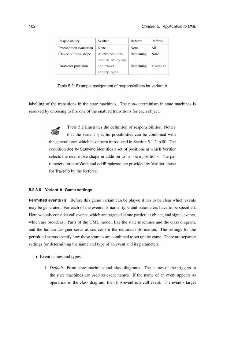
102 Chapter 5. Application to UML
Responsibility Verifier Refuter Referee
Precondition evaluation None None All
Choice of move shape At own positions Remaining None
Joe IN Studying
Parameter provision startWork Remaining TravelTo
addEmployee
Table 5.2: Example assignment of responsibilities for variant A
labelling of the transitions in the state machines. The non-determinism in state machines is
resolved by choosing to fire one of the enabled transitions for each object.
Table 5.2 illustrates the definition of responsibilities. Notice
that the variant specific possibilities can be combined with
the general ones which have been introduced in Section 5.1.2, p.80. The
condition Joe IN Studying identifies a set of positions at which Verifier
selects the next move shape in addition to her own positions. The pa-
rameters for startWork and addEmployee are provided by Verifier, those
for TravelTo by the Referee.
5.2.3.6 Variant A: Game settings
Permitted events (I) Before this game variant can be played it has to be clear which events
may be generated. For each of the events its name, type and parameters have to be specified.
Here we only consider call events, which are targeted at one particular object, and signal events,
which are broadcast. Parts of the UML model, like the state machines and the class diagram,
and the human designer serve as sources for the required information. The settings for the
permitted events specify how these sources are combined to set up the game. There are separate
settings for determining the name and type of an event and its parameters.
• Event names and types:
1. Default: From state machines and class diagrams. The names of the triggers in
the state machines are used as event names. If the name of an event appears as
operation in the class diagram, then this event is a call event. The event’s target
5.2. Property checking games 103
must be an object of the class which contains the operation corresponding to the
event name. If the event does not occur in the class diagram it is treated as a signal
event.
2. From state machines. The names of the triggers in the state machines are used as
event names and all events are signal events.
3. From class diagram. The names of classes with stereotypes Call Event or Signal
Event are used as event names. The stereotypes indicate what kind of event is
modelled. A class with stereotype Call Event must specify at which objects the
event is targeted.
• Parameters:
1. Default: From state machines. The parameters given in the triggers of transitions
are the parameters of the triggering event. If the triggers only contain the parameter
names without their types, the Explorer has to complete this information manually.
2. From state machines and class diagram: if the event name appears as operation in
the class diagram, the parameters of the operation are the parameters of the event.
Otherwise the parameters given in the triggers of state machines are used. As for
the default setting the Explorer has to add information about the parameter types if
it is missing.
3. Manual specification by the Explorer. For each event the Explorer defines a list of
parameters and their types.
Event dispatch (I) UML leaves the order in which events are dispatched from the event pool
open as a semantic variation point. This setting determines which order is used during a play
of the game variant. The dispatched event determines the next possible moves, because only
transitions which are triggered by it may be fired.
1. Default: First-In-First-Out (FIFO). The event pool corresponds to a queue and the event
which has arrived first is dispatched first.
2. Last-In-First-Out (LIFO). The event pool corresponds to a queue and the event which
has arrived last is dispatched first.
3. Random dispatch. An event is randomly selected from the event pool for each object
when a position belonging to Verifier is reached.

104 Chapter 5. Application to UML
4. Arbitrary order. At Verifier’s positions the game participant who has to choose the next
move shape selects both the event that is dispatched and the transition that is fired in
response for each object.
Firing of transitions (I) The UML state machine semantics includes priority rules for transi-
tions which are in conflict [UML03b, p.493]. This setting determines whether these rules are
used during the game or not.
1. Default: The priority rules are ignored. The game participant who has to react to the
dispatched event can choose from all transitions which are enabled.
2. The priority rules are used. That means only transitions with the highest priority may be
fired for the current event. When one of Verifier’s positions is reached during a play, the
priorities of the enabled transitions must be computed after the legal moves have been
determined. The moves which involve transitions with low priority are excluded from
the set of next possible moves. Notice that there may be more than one transition with the
same priority, i.e. the game participant who selects the next move shape may still have
to choose a transition. Since the priority rules apply only to transitions whose guard
conditions are evaluated to true, the priorities cannot be computed upfront when the
game is set up. Instead they are determined during a play when the move preconditions
at the current position have been evaluated.
Discarding of call events (I) According to the UML specification an event is discarded if
it does not trigger a transition. This convention applies to all events, no matter of what kind
they are. We believe that it may be useful to have the option of treating call events in a stricter
manner. A call event usually corresponds to the invocation of an operation on an object. If
the object does not react to the invocation and the event is discarded, the operation’s effect on
the object state has not been modelled in the state machine. The designer may have decided
deliberately to omit the operation because the object’s reaction to it is not very interesting. It
could also be the case that the modeller has forgotten to add a transition for the operation or
that he has postponed this task to a later design stage. Using a setting that forbids discarding
call events points the designer to potentially missing transitions in the state machines.
5.2. Property checking games 105
• Default: A call event is discarded if it does not trigger a transition.
• A call event must not be discarded. If a call event does not trigger a transition, the game
participant who has to fire a transition in response cannot move.
Execution of activities (I) For this game variant we have assumed that all activities in the
state machines consist of InvocationActions which result in the generation of a new event. The
settings have to define whether these actions are synchronous or asynchronous. Moreover they
must specify how the parameters and target object of the generated events are determined. This
can be done by using parts of the state machine which contains the activity or by interaction
with the Explorer.
If an object performs a state transition which results in a synchronous invocation, it cannot
enter the next state configuration before the events which are generated during the transition
have been completely processed. That means the object must wait until the invoked behaviours
are completed. During this time the object cannot process any events [UML03b, p.491] which
may cause deadlocks in case of recursive cycles of synchronous invocations. This issue has
been discussed in detail in [TS03]. The example below demonstrates how the transition from
one state configuration to another is recorded in the positions for objects which are waiting
for the completion of a synchronous invocation. In this case the run-to-completion step of the
state machine does not correspond to exactly one move anymore, but is stretched to several
consecutive moves.
• Synchronous/asynchronous invocation:
1. Default The actions in activities are always treated as asynchronous InvocationAc-
tions.
2. The actions in activities are always treated as synchronous InvocationActions.
3. An action in an activity is treated as a synchronous InvocationAction if it corre-
sponds to a CallOperationAction [UML03b, p.227], and as an asynchronous invo-
cation otherwise. Here we assume that all InvocationActions whose name, parame-
ter signature and type of target object match with an operation in the class diagram
are CallOperationActions.
4. The Explorer defines manually for all actions in the state machine whether they are
synchronous or asynchronous InvocationActions.

106 Chapter 5. Application to UML
• Object expression:
1. Default: From the state machine. If the object expression is not specified or cannot
be resolved, the event is targeted at all objects in the object collection.
2. Provided by the Explorer when the invocation is performed.
• Parameter values:
1. Default: From the state machine. If at least one element of the parameter list
cannot be resolved, the complete parameter list is discarded and an event with no
parameters is generated.
2. Provided by the Explorer when the invocation is performed.
Figure 5.9 shows an excerpt of the arena for the example game
where the effects at transitions t17 and t24 are interpreted as
synchronous InvocationActions. At position p9 the state configuration
for Joe records that the object must wait until event e5 has been com-
pletely processed.
The two transitions which may be fired in response to e5 in the state
machine for PubX are t26 and t24. Transition t26 does not have an effect
attached and PubX immediately enters a new state configuration. At this
point the processing of e5 is finished. The event does not appear in any
of the event pools and none of the objects is currently processing it. That
means Joe can complete the transition to At Work.
In case of transition t24 another synchronous invocation takes place.
The invocation is targeted at Joe which is the value for parameter p at
position p9. Object PubX must wait until the new event e6 has been
processed before it can complete its transition. Since Joe is still waiting
for PubX to complete its processing of e5, it cannot dispatch and process
event e6 from its event pool at p11 and a deadlock occurs at this point.

5.2. Property checking games 107
Context
Context
Context
Italy
PubX
default
Not enough staff
empty
empty
e Employer PubX
Italy
PubX
default
Not enough staff
empty
p JoePerson
empty ...
...
Italy default empty
PubX emptyItaly
PubX
default empty
empty ...
empty
e4: firing t17
e5: addEmloyee
waiting for e5
e4: firing t17
e4
e5
waiting for e5
waiting for e6
History mappingEvent poolState configurationName
Name State configuration
ProjectPractical1
Design
Event pool
Joe Studying
History mapping
Name Type Value
p8: V
p9: V
Name ValueType
Joe
PubX: fire t24
Joe
History mappingEvent poolState configurationName
p11: V
Name Type Value
PubX: fire t26
Name Type Value
History mappingEvent poolState configurationName
Joe
p10: R
h2:
h1: Practical1
Project
Design
e4: startWork
OBJECTS
OBJECTS
PARAMETERS
PARAMETERS
OBJECTS
PARAMETERS
Joe: fire t17
PARAMETERS
OBJECTS
At Work
Enough staff
Context
e5: firing t24
e6: Work
Figure 5.9: Firing a transition with a synchronous invocation as effect in variant A
Discarding recursive synchronous invocations (I) An event corresponding to a syn-
chronous invocation is recursive if it arrives at an object which is waiting for the processing of
another event to complete. Most UML modellers who use UML state machines are not aware
of the fact that recursive synchronous invocations cause deadlocks as explained for the previ-
ous setting. In practice the run-to-completion semantics of UML is often not taken seriously,
and events that are generated by the activities are ignored. If recursive synchronous invocations
should be treated in such a relaxed manner in an exploration game, they have to be discarded.
• Default: Recursive synchronous invocations cause deadlocks.
• All events corresponding to recursive synchronous invocations are discarded.

108 Chapter 5. Application to UML
In the example shown in Figure 5.9 event e6 in Joe’s event
pool at position p11 corresponds to a recursive synchronous
invocation. If the game settings permit event e6 to be discarded Joe can
complete transition t17 at position p11 and the deadlock is avoided.
5.2.3.7 Variant A: Incrementations
The Explorer can make the following variant specific incrementations during a play:
• Add or delete a transition between two existing states.
• Add or delete a state. All transitions which point to or emerge from a state that is deleted
are also deleted.
• Change a trigger, guard or effect at a transition.
• Add or delete a state machine for an object.
• Add or delete an operation in the class diagram.
Assume the game is played with the default responsibilities,
default game settings and a winning condition stating that Re-
futer wins if a position where PubX is in Not enough staff and Joe in On
Holiday is reached. Verifier has a winning strategy for this game. If Re-
futer generates a skip event, Verifier must discard the event and should
not fire transition t20. Thus she ensures that state On Holiday is never
visited for Joe and Refuter’s winning condition never holds.
During a play of the game the Explorer realises that a student should not
go on holiday as soon as he has enough savings. Instead there should be
a trigger at transition t20 which allows the Refuter to say explicitly when
a student goes on holiday. Explorer adds the trigger goOnHoliday to the
transition. Furthermore the Explorer changes the responsibilities such
that the Referee evaluates all informally defined preconditions. Refuter
now has a possibility to win the game if he challenges by the new event.
If the Referee declares that the guard condition at t20 holds, Verifier
must fire the transition and the winning condition for Refuter holds.

5.2. Property checking games 109
5.2.3.8 Variant A: Omitted UML features
For this game variant we have not considered Submachine States [UML03b][p.478], entry
point pseudostates, exit point pseudostates, terminate pseudostates, choice vertices and de-
ferred events [UML03b][p.482]. A choice vertex is also a pseudostate. The different kinds of
Pseudostates are discussed in [UML03b][p.469].
The first four elements of the list of omitted features are all related to the concept of sub-
machines in UML state machines. Submachines have not been considered here because they
do not rise any new issues. They are “semantically equivalent to composite states defined by
the referenced state machine” [UML03b, p.482] and allow decomposition of one state machine
into several.
Choice vertices are more interesting and could be treated in a way which is similar to syn-
chronous invocations (see game setting “Execution of Activities”, p.105). Since a choice vertex
is dynamic, the guard conditions at the transitions that emerge from it cannot be evaluated be-
fore the vertex has been reached. Thus a compound transition via a choice vertex must be fired
in two moves. The transition segments leading to the choice point are fired in the first move.
The target position must record that the object has reached a choice vertex. This position corre-
sponds to an intermediate system state like the ones which record that an object is waiting for
the processing of an event in case of synchronous activity executions. The guard conditions at
the transition segments emerging from the choice vertex constitute the preconditions for pro-
ceeding with the transition in different ways. After their evaluation the game participant who
is responsible for selecting the next move shape decides which segment is fired to complete the
transition to a new stable state configuration.
Deferred events could easily be added to this game variant because they merely influence
the way in which the event pools are working. If an event is deferred in a particular state,
it remains in the event pool until the object reaches a state where the event is not deferred
anymore.

110 Chapter 5. Application to UML
SUMMARY OF VARIANT A
Prerequisites• Object collection• Class diagram• Set of state machines with class context
Positions• For each object in the object collection
– an abstract state configuration in form of a tree,– an event pool,– a history mapping from history pseudostates to state configurations
• A set of parameters which are in scope at the position
Moves• Generating an event• Firing a set of enabled transitions• Skipping the turn
Winning conditions• State combinations• Event occurrences• Temporal properties
Responsibility assignment• Precondition evaluation, choice of move shape: for positions with particular combinations of states or
events• Parameter provision: for moves which correspond to the generation of events with particular names• Resolution of non-determinism: not applicable
Incrementations• Add or delete a transition or state• Change a trigger, guard condition or effect at a transition• Add or delete a state machine for an object• Add or delete an operation in the class diagram
Figure 5.10: Summary of variant A

5.2. Property checking games 111
5.2.4 Variant B: Activity diagrams
Activity diagrams can be used on a wide range of abstraction levels. They most frequently
model system behaviour on a high level of abstraction where the meaning of actions is often
specified informally. At an early design stage the designer may want to play a game based on
this diagram type only to examine whether the actions are executed in a sensible order. For this
purpose it does not matter if the activity diagrams are informally defined.
As soon as the modeller wants to check constraints referring to object states for the most
interesting or critical parts of the system by playing a game, more information is necessary.
Within the exploration game framework information can be added or made more precise by
interaction with the game participants. The general game settings can enforce that the Explorer
adds more detail to the design model by position changes during a play (see Section 5.1.3, p.83).
Alternatively, the game participants may interpret the UML model according to their responsi-
bilities and the game settings without changing the game definition.
5.2.4.1 Variant B: Prerequisites
This game variant is based on an object collection, a class diagram and a set of activity dia-
grams. Optionally the initial object collection may be provided by an instance diagram. The
class diagram determines which types of objects are permitted in the object collection and how
their states are defined. In this game variant concrete state configurations refer to object states
in terms of the objects’ attribute values and links. An object without attribute values and links
is in a default state which is not changed during a play. The actions in the activity diagrams
may modify the state of the objects in the object collection or invoke other activities.
Controller<<Interface>>
Alarm
compDose: intcumulativeDose: intmaxSingleDose: int
deliverInsulin(dose:int)
<<Interface>>Blood Sensor
getReading():int
Insulin Pump<<Interface>><<Interface>>
Clock maxCumDose:int
init()computeDose()
1
alarm
clock
sensor
pump
1
1 1 1 1
1 1turnOff()turnOn()
bs: Blood Sensor
ip: Insulin Pumpcl:Clock
a:Alarmco:Controller
clock
alarm sensor
pump
maxSingleDose = 4
maxCumDose = 25
Figure 5.11: Example class and instance diagram for variant B

112 Chapter 5. Application to UML
������������������
Deliver Insulinf4:f3:
n3:
Act1: Compute and deliver insulin dose
f1:n1:
f2:n2:
<<precondition>>: System test passed
Read Sensor Compute Dose
Figure 5.12: Activity diagram modelling the operation of Controller for variant B
As example we consider parts of the control software for an
insulin pump. This example is motivated by a case study used
in [Som04]. The insulin pump system is a safety-critical system which
delivers regular doses of insulin to diabetics to reduce the patient’s sugar
level. The left part of Figure 5.11 shows its components in the form of
a UML class diagram.
Here we assume that the interfaces of the hardware components are fixed
and cannot be modified. The Controller is variable and has to be defined
by the designer. The object collection is given by the objects in the
instance diagram shown in the right part of Figure 5.11, i.e. it consists
of a:Alarm, cl:Clock, co:Controller, bs:Blood Sensor and ip:Insulin
Pump.
The basic functionality of the Controller is modelled by the UML activ-
ity diagram Act1 as shown in Figure 5.12. The action nodes in activity
diagrams are labelled by n1, n2, . . . and the control flows by f1, f2, . . . for
later reference. Action Compute Dose invokes activity Act2 as shown
in Figure 5.13. Given the current and previous reading as input pa-
rameters, the activity computes the insulin dose that is delivered to the
patient. Notice that it depends on the analysis of the reading how the
dose is computed. If the sugar level is high, two different algorithms are
used to ensure that the computed dose is optimal.
5.2.4.2 Variant B: Positions
A position in this game variant consists of a concrete state configuration for each object in the
object collection and a set of running activities with their markings. A marking is specified with
respect to the input and output pins of actions, and the control flows in the diagram. The set of

5.2. Property checking games 113
� � � ���������
[Level high]
n5:
Algorithm2 for
[Level low][Level normal & rising]
Act2: Compute Dose
Analyse Reading
<<precondition>>: currentReading>0<<postcondition>>: compDose<maxSingleDosePreviousReading: double
CurrentReading: doublef5:
n6:
Algorithm for Algorithm1 for alarm.turnOn()
f6:
n7: n9:
n11:
f11:f10:
f12: f13:
f14:
f8:f7: f9:
n10:
compDose=d
d:int
f15:
f16:
n8:Normal Level
Merge Results
High Level High Level
<<context>>: Controller
CurrentReading
PreviousReading
Figure 5.13: Activity diagram Compute Dose for variant B
parameters contains the object tokens that exist for each activity at this position. Since control
tokens do not have values they are only recorded in the marking of the activities. The posi-
tions at which no activities are running belong to Refuter, all others to Verifier. If an instance
diagram is provided, it determines the object collection and concrete state configuration of the
initial position. Otherwise the default values for attributes in the class diagram (see Property,
[UML03b, p.89]) are used. According to the default game settings any attribute values or links
which are not specified by the instance or class diagram are interpreted as undefined. Initially
the sets of parameters and running activities are empty.
Figure 5.14 shows the initial position for our example. The
only object which has attributes and links is co. All other
objects are in the default state. They do not have links to co because
navigation to Controller is not possible according to the direction of
the associations in the class diagram. The values for attributes comp-
Dose and cumulativeDose are undefined because they are not given in
the instance or class diagram.
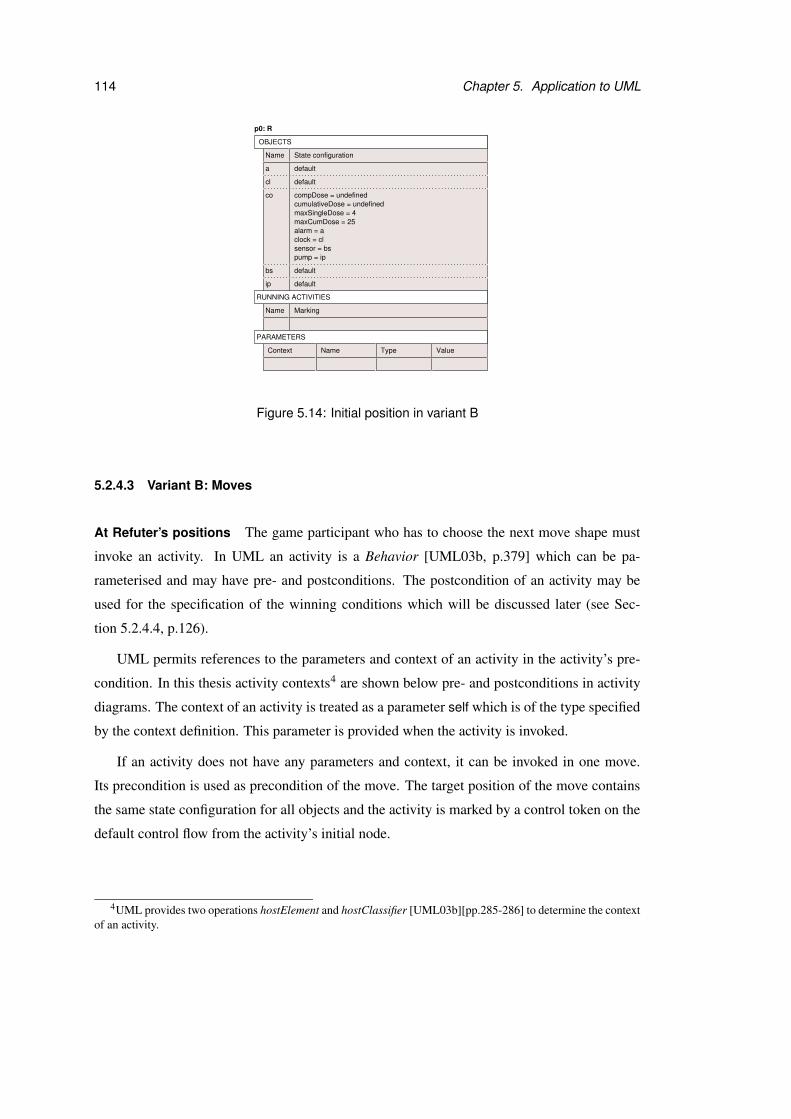
114 Chapter 5. Application to UML
State configurationName
Name Marking
TypeName Value
cl
a
co compDose = undefinedcumulativeDose = undefined
alarm = aclock = clsensor = bs
defaultbs
ip default
maxSingleDose = 4
default
default
Context
p0: R
OBJECTS
RUNNING ACTIVITIES
PARAMETERS
pump = ip
maxCumDose = 25
Figure 5.14: Initial position in variant B
5.2.4.3 Variant B: Moves
At Refuter’s positions The game participant who has to choose the next move shape must
invoke an activity. In UML an activity is a Behavior [UML03b, p.379] which can be pa-
rameterised and may have pre- and postconditions. The postcondition of an activity may be
used for the specification of the winning conditions which will be discussed later (see Sec-
tion 5.2.4.4, p.126).
UML permits references to the parameters and context of an activity in the activity’s pre-
condition. In this thesis activity contexts4 are shown below pre- and postconditions in activity
diagrams. The context of an activity is treated as a parameter self which is of the type specified
by the context definition. This parameter is provided when the activity is invoked.
If an activity does not have any parameters and context, it can be invoked in one move.
Its precondition is used as precondition of the move. The target position of the move contains
the same state configuration for all objects and the activity is marked by a control token on the
default control flow from the activity’s initial node.
4UML provides two operations hostElement and hostClassifier [UML03b][pp.285-286] to determine the contextof an activity.

5.2. Property checking games 115
Figure 5.15 shows a move representing the invocation of ac-
tivity Act1. The activity does not have any parameters or con-
text definition and its precondition is used for the move definition. The
marking at the target position consists of a control token on flow f1
which emerges from the initial node.
......
Act1 f1: control
......
State configurationName
Name Marking
Name Type Value
[System test passed]
invoke Act1
p2: V
State configurationName
Name Marking
Name Type Value
p1: R
Context Context
OBJECTS
RUNNING ACTIVITIES
PARAMETERS
OBJECTS
RUNNING ACTIVITIES
PARAMETERS
Figure 5.15: Example move from Refuter’s position in variant B
In UML the tokens for each invocation of an activity can be treated separately or handled by
a single execution [UML03b, p.285]. Here we do not consider single execution of an activity.
For each invocation of an activity a new marking is generated and recorded in the target position
of the corresponding move. That means an activity can appear several times as running activity
with different markings. In order to distinguish the different invocations and their parameters,
they are recorded by unique names (e.g. Act2-1, Act2-2, . . . ) in the positions where this is
necessary.
If an activity has parameters or a context definition, the activity’s precondition may depend
on them. In case of an informally defined precondition the parameter names may not appear in
the precondition although their values are needed by the game participants to decide about the
legality of the move. The exploration game framework only allows references to parameters
which are known at the source position of a move in the move’s precondition. The consequence
for this game variant is that the activity’s precondition cannot be used directly in a move which
corresponds to the invocation of a parameterised activity. Instead the invocation of the activity
has to be split into two different moves. First the parameters for the activity are provided,
second the activity is invoked.
The precondition of the first preparatory move is true and its parameters are given by the
activity’s parameters and context definition. The parameter self for the context is always sup-
plied first. During the move the parameters and their values are added to the parameter set. The
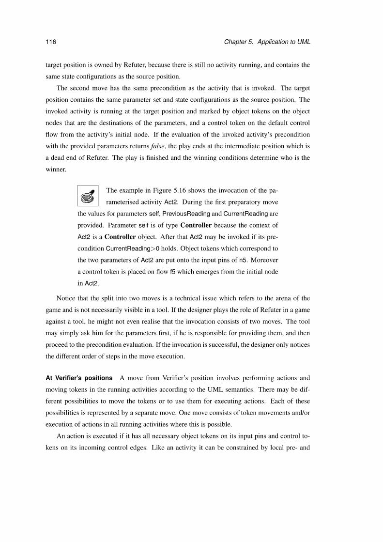
116 Chapter 5. Application to UML
target position is owned by Refuter, because there is still no activity running, and contains the
same state configurations as the source position.
The second move has the same precondition as the activity that is invoked. The target
position contains the same parameter set and state configurations as the source position. The
invoked activity is running at the target position and marked by object tokens on the object
nodes that are the destinations of the parameters, and a control token on the default control
flow from the activity’s initial node. If the evaluation of the invoked activity’s precondition
with the provided parameters returns false, the play ends at the intermediate position which is
a dead end of Refuter. The play is finished and the winning conditions determine who is the
winner.
The example in Figure 5.16 shows the invocation of the pa-
rameterised activity Act2. During the first preparatory move
the values for parameters self, PreviousReading and CurrentReading are
provided. Parameter self is of type Controller because the context of
Act2 is a Controller object. After that Act2 may be invoked if its pre-
condition CurrentReading>0 holds. Object tokens which correspond to
the two parameters of Act2 are put onto the input pins of n5. Moreover
a control token is placed on flow f5 which emerges from the initial node
in Act2.
Notice that the split into two moves is a technical issue which refers to the arena of the
game and is not necessarily visible in a tool. If the designer plays the role of Refuter in a game
against a tool, he might not even realise that the invocation consists of two moves. The tool
may simply ask him for the parameters first, if he is responsible for providing them, and then
proceed to the precondition evaluation. If the invocation is successful, the designer only notices
the different order of steps in the move execution.
At Verifier’s positions A move from Verifier’s position involves performing actions and
moving tokens in the running activities according to the UML semantics. There may be dif-
ferent possibilities to move the tokens or to use them for executing actions. Each of these
possibilities is represented by a separate move. One move consists of token movements and/or
execution of actions in all running activities where this is possible.
An action is executed if it has all necessary object tokens on its input pins and control to-
kens on its incoming control edges. Like an activity it can be constrained by local pre- and
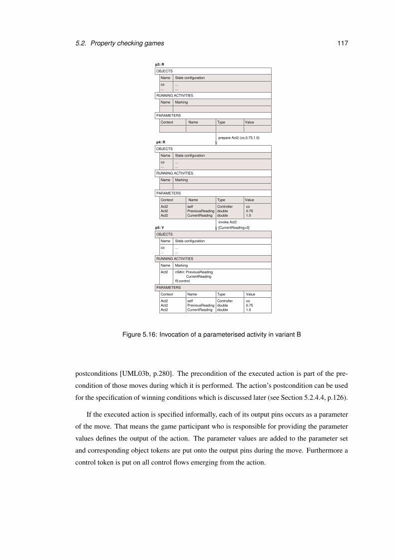
5.2. Property checking games 117
......
...
...
Act2CurrentReading
n5#in: PreviousReading
......
f5:control
prepare Act2 (co,0.75,1.0)
[CurrentReading>0]
invoke Act2
......
...
PreviousReading doubledoubleCurrentReadingAct2
Act2selfAct2 Controller co
0.751.0
PreviousReading doubledoubleCurrentReadingAct2
Act2selfAct2 Controller co
0.751.0
Name Marking
Name Type Value
Name State configuration
co
p4: R
Name Marking
ValueTypeName
Name State configuration
co
p5: V
Name Marking
Name Type Value
Name State configuration
co
p3: R
Context
Context
Context
RUNNING ACTIVITIES
PARAMETERS
OBJECTS
RUNNING ACTIVITIES
PARAMETERS
OBJECTS
RUNNING ACTIVITIES
PARAMETERS
OBJECTS
Figure 5.16: Invocation of a parameterised activity in variant B
postconditions [UML03b, p.280]. The precondition of the executed action is part of the pre-
condition of those moves during which it is performed. The action’s postcondition can be used
for the specification of winning conditions which is discussed later (see Section 5.2.4.4, p.126).
If the executed action is specified informally, each of its output pins occurs as a parameter
of the move. That means the game participant who is responsible for providing the parameter
values defines the output of the action. The parameter values are added to the parameter set
and corresponding object tokens are put onto the output pins during the move. Furthermore a
control token is put on all control flows emerging from the action.
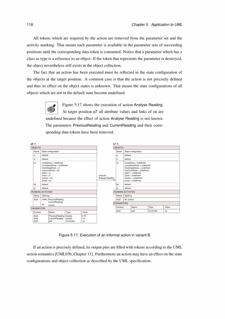
118 Chapter 5. Application to UML
All tokens which are required by the action are removed from the parameter set and the
activity marking. That means each parameter is available in the parameter sets of succeeding
positions until the corresponding data token is consumed. Notice that a parameter which has a
class as type is a reference to an object. If the token that represents the parameter is destroyed,
the object nevertheless still exists in the object collection.
The fact that an action has been executed must be reflected in the state configuration of
the objects at the target position. A common case is that the action is not precisely defined
and thus its effect on the object states is unknown. That means the state configurations of all
objects which are not in the default state become undefined.
Figure 5.17 shows the execution of action Analyse Reading.
At target position p7 all attribute values and links of co are
undefined because the effect of action Analyse Reading is not known.
The parameters PreviousReading and CurrentReading and their corre-
sponding data tokens have been removed.
Act2CurrentReading
control
n5#in: PreviousReading
f5:
cumulativeDose = undefined
clock = cl
ip
Analyse Readingexecute
Act2
cumulativeDose = undefined
ip
clock = undefined
f6: control
Act2 PreviousReading double 0.75doubleCurrentReading 1.0Act2
selfAct2 Controller co
Name Marking
ValueTypeName
pump = ip
maxCumDose = 25
defaulta
cl default
compDose = undefined
maxSingleDose = 4
alarm = a
sensor = bs
default
default
co
bs
Name State configuration
p6: V
Name Marking
defaulta
cl default
compDose = undefined
default
default
co
bs
Name State configuration
p7: V
maxSingleDose = undefinedmaxCumDose = undefinedalarm = undefined
sensor = undefinedpump = undefined
ValueTypeName
Act2 self Controller coContext
Context
RUNNING ACTIVITIES
PARAMETERS
OBJECTS
RUNNING ACTIVITIES
OBJECTS
PARAMETERS
Figure 5.17: Execution of an informal action in variant B
If an action is precisely defined, its output pins are filled with tokens according to the UML
action semantics [UML03b, Chapter 11]. Furthermore an action may have an effect on the state
configurations and object collection as described by the UML specification.
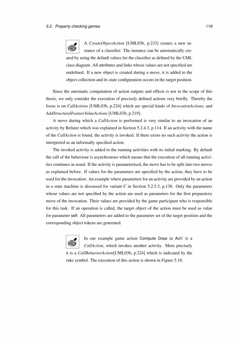
5.2. Property checking games 119
A CreateObjectAction [UML03b, p.233] creates a new in-
stance of a classifier. The instance can be automatically cre-
ated by using the default values for the classifier as defined by the UML
class diagram. All attributes and links whose values are not specified are
undefined. If a new object is created during a move, it is added to the
object collection and its state configuration occurs in the target position.
Since the automatic computation of action outputs and effects is not in the scope of this
thesis, we only consider the execution of precisely defined actions very briefly. Thereby the
focus is on CallActions [UML03b, p.224] which are special kinds of InvocationActions, and
AddStructuralFeatureValueActions [UML03b, p.219].
A move during which a CallAction is performed is very similar to an invocation of an
activity by Refuter which was explained in Section 5.2.4.3, p.114. If an activity with the name
of the CallAction is found, the activity is invoked. If there exists no such activity the action is
interpreted as an informally specified action.
The invoked activity is added to the running activities with its initial marking. By default
the call of the behaviour is asynchronous which means that the execution of all running activi-
ties continues as usual. If the activity is parameterised, the move has to be split into two moves
as explained before. If values for the parameters are specified by the action, they have to be
used for the invocation. An example where parameters for an activity are provided by an action
in a state machine is discussed for variant C in Section 5.2.5.3, p.138. Only the parameters
whose values are not specified by the action are used as parameters for the first preparatory
move of the invocation. Their values are provided by the game participant who is responsible
for this task. If an operation is called, the target object of the action must be used as value
for parameter self. All parameters are added to the parameter set of the target position and the
corresponding object tokens are generated.
In our example game action Compute Dose in Act1 is a
CallAction, which invokes another activity. More precisely
it is a CallBehaviorAction[UML03b, p.224] which is indicated by the
rake symbol. The execution of this action is shown in Figure 5.18.
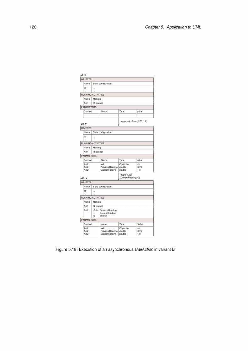
120 Chapter 5. Application to UML
......
...
......
...
Act1 f2: control
Act1 f2: control
prepare Act2 (co, 0.75, 1.0)
......
...
[CurrentReading>0]invoke Act2
Act2CurrentReading
n5#in: PreviousReading
f5: control
Name Marking
Name Type Value
Name State configuration
co
Name Marking
Name Type Value
Name State configuration
co
p8: V
p9: V
Act2 PreviousReading doubledoubleCurrentReading
selfAct2 Controller co0.751.0Act2
Name Marking
Name State configuration
co
Act1 f3: control
p10: V
ValueTypeName
PreviousReading doubledoubleCurrentReadingAct2
Act2selfAct2 Controller co
0.751.0
Context
Context
Context
RUNNING ACTIVITIES
PARAMETERS
OBJECTS
RUNNING ACTIVITIES
PARAMETERS
OBJECTS
RUNNING ACTIVITIES
OBJECTS
PARAMETERS
Figure 5.18: Execution of an asynchronous CallAction in variant B
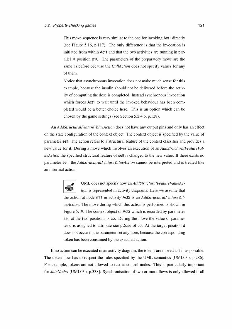
5.2. Property checking games 121
This move sequence is very similar to the one for invoking Act1 directly
(see Figure 5.16, p.117). The only difference is that the invocation is
initiated from within Act1 and that the two activities are running in par-
allel at position p10. The parameters of the preparatory move are the
same as before because the CallAction does not specify values for any
of them.
Notice that asynchronous invocation does not make much sense for this
example, because the insulin should not be delivered before the activ-
ity of computing the dose is completed. Instead synchronous invocation
which forces Act1 to wait until the invoked behaviour has been com-
pleted would be a better choice here. This is an option which can be
chosen by the game settings (see Section 5.2.4.6, p.128).
An AddStructuralFeatureValueAction does not have any output pins and only has an effect
on the state configuration of the context object. The context object is specified by the value of
parameter self. The action refers to a structural feature of the context classifier and provides a
new value for it. During a move which involves an execution of an AddStructuralFeatureVal-
ueAction the specified structural feature of self is changed to the new value. If there exists no
parameter self, the AddStructuralFeatureValueAction cannot be interpreted and is treated like
an informal action.
UML does not specify how an AddStructuralFeatureValueAc-
tion is represented in activity diagrams. Here we assume that
the action at node n11 in activity Act2 is an AddStructuralFeatureVal-
ueAction. The move during which this action is performed is shown in
Figure 5.19. The context object of Act2 which is recorded by parameter
self at the two positions is co. During the move the value of parame-
ter d is assigned to attribute compDose of co. At the target position d
does not occur in the parameter set anymore, because the corresponding
token has been consumed by the executed action.
If no action can be executed in an activity diagram, the tokens are moved as far as possible.
The token flow has to respect the rules specified by the UML semantics [UML03b, p.286].
For example, tokens are not allowed to rest at control nodes. This is particularly important
for JoinNodes [UML03b, p.338]. Synchronisation of two or more flows is only allowed if all
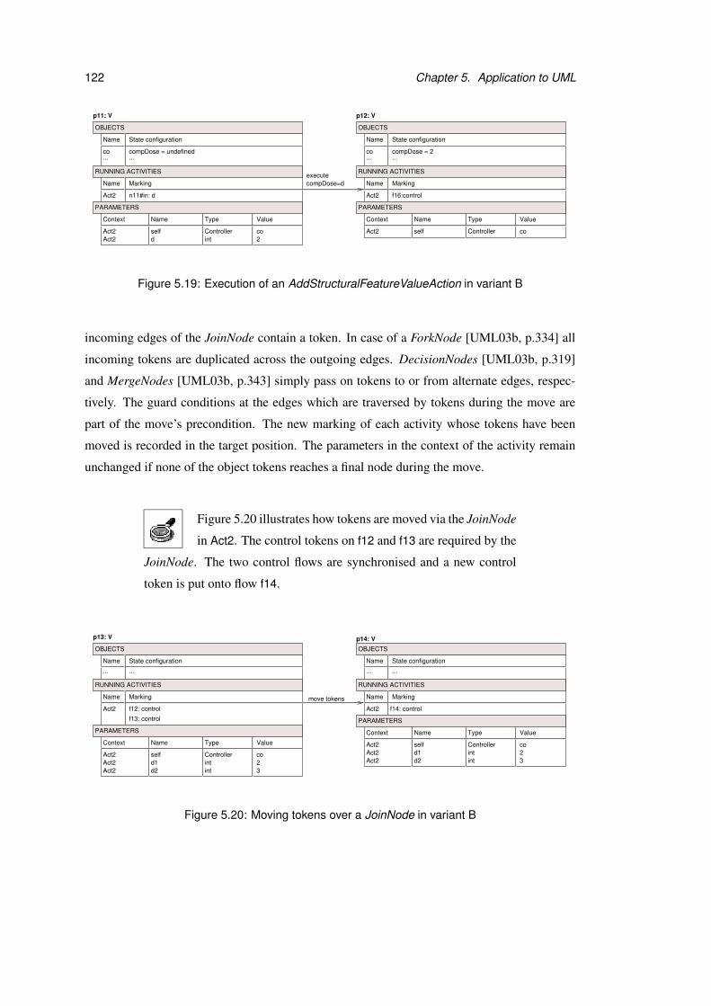
122 Chapter 5. Application to UML
compDose=dexecute
n11#in: d f16:control
Name State configuration
co... ...
Name Marking
Act2
compDose = 2
ValueTypeName
Act2 self Controller co
Name State configuration
co compDose = undefined... ...
Name Marking
Act2
p11: V p12: V
ValueTypeName
Act2 self Controller co
Context Context
OBJECTS
RUNNING ACTIVITIES
PARAMETERS
OBJECTS
RUNNING ACTIVITIES
PARAMETERS
Act2 d int 2
Figure 5.19: Execution of an AddStructuralFeatureValueAction in variant B
incoming edges of the JoinNode contain a token. In case of a ForkNode [UML03b, p.334] all
incoming tokens are duplicated across the outgoing edges. DecisionNodes [UML03b, p.319]
and MergeNodes [UML03b, p.343] simply pass on tokens to or from alternate edges, respec-
tively. The guard conditions at the edges which are traversed by tokens during the move are
part of the move’s precondition. The new marking of each activity whose tokens have been
moved is recorded in the target position. The parameters in the context of the activity remain
unchanged if none of the object tokens reaches a final node during the move.
Figure 5.20 illustrates how tokens are moved via the JoinNode
in Act2. The control tokens on f12 and f13 are required by the
JoinNode. The two control flows are synchronised and a new control
token is put onto flow f14.
f12: control
move tokens
f14: control
p13: V
Name State configuration
...
Name Marking
Act2
f13: control
ValueTypeName
Act2 self Controller co
...
p14: V
Name State configuration
...
Name Marking
Act2
ValueTypeName
Act2 self Controller co
...
Context
Context
OBJECTS
RUNNING ACTIVITIES
PARAMETERS
Act2 intd2 3Act2 int 2d1
OBJECTS
RUNNING ACTIVITIES
Act2 intd2 3Act2 int 2d1
PARAMETERS
Figure 5.20: Moving tokens over a JoinNode in variant B
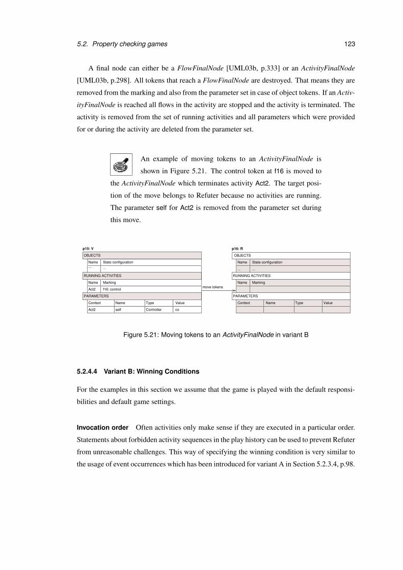
5.2. Property checking games 123
A final node can either be a FlowFinalNode [UML03b, p.333] or an ActivityFinalNode
[UML03b, p.298]. All tokens that reach a FlowFinalNode are destroyed. That means they are
removed from the marking and also from the parameter set in case of object tokens. If an Activ-
ityFinalNode is reached all flows in the activity are stopped and the activity is terminated. The
activity is removed from the set of running activities and all parameters which were provided
for or during the activity are deleted from the parameter set.
An example of moving tokens to an ActivityFinalNode is
shown in Figure 5.21. The control token at f16 is moved to
the ActivityFinalNode which terminates activity Act2. The target posi-
tion of the move belongs to Refuter because no activities are running.
The parameter self for Act2 is removed from the parameter set during
this move.
move tokensf16: control
......
p15: V
Name State configuration... ...
Name Marking
Act2
ValueTypeName
Act2 self Controller co
Context
State configurationName
Name Marking
Name Type Value
p16: R
Context
OBJECTS
RUNNING ACTIVITIES
PARAMETERS
OBJECTS
RUNNING ACTIVITIES
PARAMETERS
Figure 5.21: Moving tokens to an ActivityFinalNode in variant B
5.2.4.4 Variant B: Winning Conditions
For the examples in this section we assume that the game is played with the default responsi-
bilities and default game settings.
Invocation order Often activities only make sense if they are executed in a particular order.
Statements about forbidden activity sequences in the play history can be used to prevent Refuter
from unreasonable challenges. This way of specifying the winning condition is very similar to
the usage of event occurrences which has been introduced for variant A in Section 5.2.3.4, p.98.
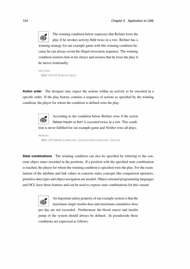
124 Chapter 5. Application to UML
The winning condition below expresses that Refuter loses the
play if he invokes activity Act2 twice in a row. Refuter has a
winning strategy for our example game with this winning condition be-
cause he can always avoid the illegal invocation sequence. The winning
condition restricts him in his choice and ensures that he loses the play if
he moves irrationally.
Verifier
NEXT ACTIVITY(Act2)=Act2
Action order The designer may expect the actions within an activity to be executed in a
specific order. If the play history contains a sequence of actions as specified by the winning
condition, the player for whom the condition is defined wins the play.
According to the condition below Refuter wins if the action
Deliver Insulin in Act1 is executed twice in a row. This condi-
tion is never fulfilled for our example game and Verifier wins all plays.
Refuter
NEXT ACTION(Act1:Deliver Insulin)=Act1:Deliver Insulin
State combinations The winning condition can also be specified by referring to the con-
crete object states recorded in the positions. If a position with the specified state combination
is reached, the player for whom the winning condition is specified wins the play. For the exam-
ination of the attribute and link values in concrete states concepts like comparison operators,
primitive data types and object navigation are needed. Object-oriented programming languages
and OCL have these features and can be used to express state combinations for this variant.
An important safety property of our example system is that the
maximum single insulin dose and maximum cumulative dose
per day are not exceeded. Furthermore the blood sensor and insulin
pump of the system should always be defined. In pseudocode these
conditions are expressed as follows:
5.2. Property checking games 125
Refuter
co.compDose > co.maxSingleDose OR
co.cumulativeDose > maxCumDose OR
co.sensor EQUALS undefined OR
co.pump EQUALS undefined
Refuter wins all plays of this game easily. Both Act1 and Act2 start with
an informally defined action. According to the default game settings
sensor and pump are undefined after the execution of such an action.
That means Refuter’s winning condition holds after the first informally
defined action has been performed and he wins the game.
In OCL these conditions are formulated as an invariant on class level:
context Controller inv:
self.compDose <= self.maxSingleDose and
self.cummulativeDose <= self.maxCumDose and
not(self.sensor.oclIsUndefined or
self.pump.oclIsUndefined)
UML does not specify whether an invariant must hold during the execution of an activity.
For activities that represent methods it is not sensible to request this because the object is in
an unstable state during the execution. However, for activity diagrams on a high abstraction
level involving actions performed by different objects a strict interpretation is often appropriate.
Here invariants are interpreted strictly and have to hold any time.
Activity marking Another part of the position which may be used in the winning condition
is the marking of the running activities. Reaching a position where an activity is marked in a
specific way can be defined as a win for one of the players.
The winning condition below expresses that there should not
be control tokens on f3 in Act1 and f5 in Act2 at the same time.
Refuter wins all plays during which he invokes Act1. Since the CallAc-
tion at node n2 is asynchronous, Refuter’s winning condition holds after
the execution of the action.
Refuter
f3:control IN Act1 AND f5:control IN Act2
126 Chapter 5. Application to UML
Postconditions In this game variant it is also possible to use postconditions at actions and
activities for the definition of winning conditions. If a postcondition is violated during a play,
Refuter wins.
Consider the postcondition of activity Act2, which specifies
that compDose should be less than maxSingleDose after the
activity has been completed. If this condition is violated for the context
object of the activity, Refuter wins the play.
If our example game is played with the default responsibilities, the post-
conditions of the activities as winning conditions and a move limit for
Refuter, Verifier can easily win. During the execution of Act2 she owns
all positions that are visited and is thus responsible for all tasks. That
means she has the power to provide the output values for the actions at
n6 and n10. If Verifier chooses values which respect the postcondition
of Act2 she can always continue to play and wins as soon as the move
limit is reached.
5.2.4.5 Variant B: Responsibilities
State combinations can be used to identify the positions at which the game participants are re-
sponsible for evaluating informal preconditions or selecting the next move shape. Additionally
these responsibilities can be assigned by referring to the marking of activities. For example, a
game participant may be assigned responsibility for all positions where a token is on a specific
node of an activity. The only parameterised moves in this game variant are activity invocations
and the execution of informally specified actions with output parameters. Thus the responsi-
bility for providing parameters is defined for sets of specific activities and actions.
There is often more than one possibility to move the tokens in the activity diagrams. The
corresponding moves never have parameters and their preconditions may be identical. For
instance, consider a set of nodes which compete for a token and whose incoming flows do not
have any guard conditions. In this case the moves representing token movements belong to the
same move shape, because their preconditions are all the same. They only differ in the activity
markings at their target positions. The responsibility for resolving non-determinism like this is
assigned with respect to the marking of the running activities at the move’s source position.
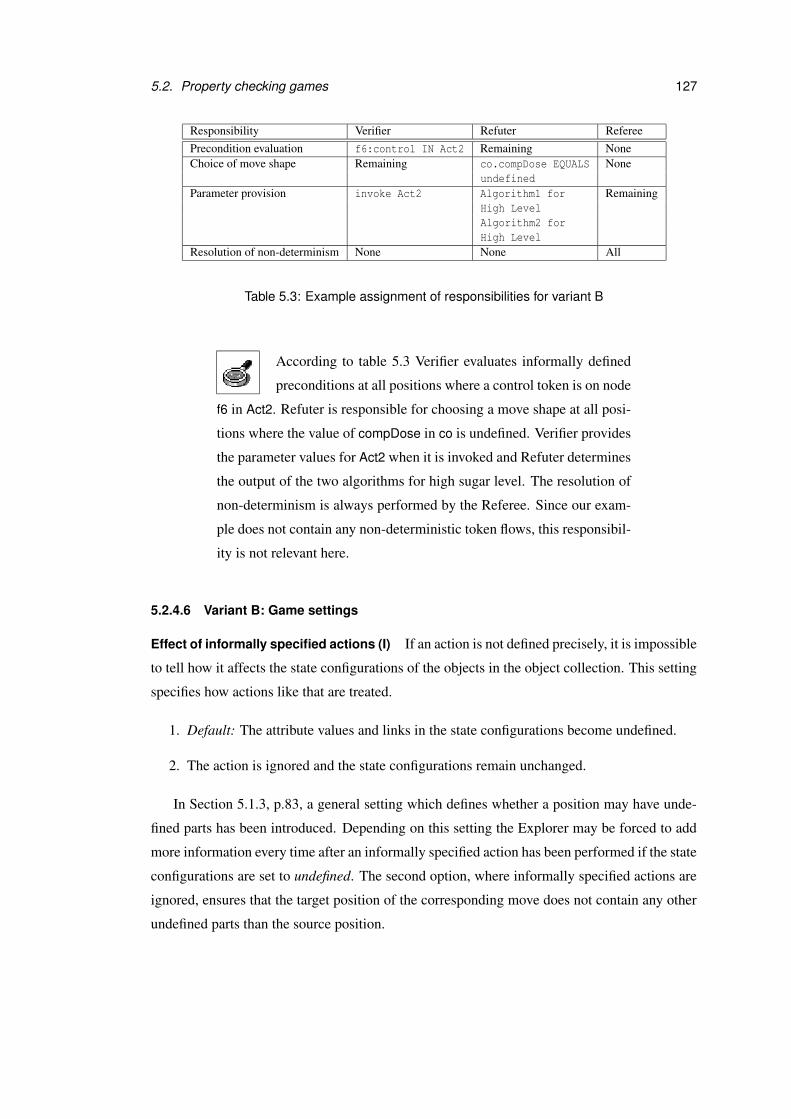
5.2. Property checking games 127
Responsibility Verifier Refuter RefereePrecondition evaluation f6:control IN Act2 Remaining NoneChoice of move shape Remaining co.compDose EQUALS None
undefinedParameter provision invoke Act2 Algorithm1 for Remaining
High LevelAlgorithm2 forHigh Level
Resolution of non-determinism None None All
Table 5.3: Example assignment of responsibilities for variant B
According to table 5.3 Verifier evaluates informally defined
preconditions at all positions where a control token is on node
f6 in Act2. Refuter is responsible for choosing a move shape at all posi-
tions where the value of compDose in co is undefined. Verifier provides
the parameter values for Act2 when it is invoked and Refuter determines
the output of the two algorithms for high sugar level. The resolution of
non-determinism is always performed by the Referee. Since our exam-
ple does not contain any non-deterministic token flows, this responsibil-
ity is not relevant here.
5.2.4.6 Variant B: Game settings
Effect of informally specified actions (I) If an action is not defined precisely, it is impossible
to tell how it affects the state configurations of the objects in the object collection. This setting
specifies how actions like that are treated.
1. Default: The attribute values and links in the state configurations become undefined.
2. The action is ignored and the state configurations remain unchanged.
In Section 5.1.3, p.83, a general setting which defines whether a position may have unde-
fined parts has been introduced. Depending on this setting the Explorer may be forced to add
more information every time after an informally specified action has been performed if the state
configurations are set to undefined. The second option, where informally specified actions are
ignored, ensures that the target position of the corresponding move does not contain any other
undefined parts than the source position.
128 Chapter 5. Application to UML
Missing information for formally specified actions (I) Some formally specified actions re-
fer to a self object which is provided by the activity’s context. They may access or modify the
context object’s attribute values and links. This setting determines what should happen if there
is either no context specified for the activity, or if a part of the context object which is required
by the action is undefined.
1. Default: Treat the action as informally specified. The action’s effect on the objects in the
object collection is considered as unknown.
2. Manual specification by the Explorer. The Explorer provides a context object of appro-
priate type if there exists no self parameter at the current position. Moreover the Explorer
completes the information about the parts of the object which are relevant for the action.
Synchronous/asynchronous invocation (I) An activity may contain InvocationActions
which invoke other activities. These invocations can either be asynchronous or synchronous.
If an InvocationAction is synchronous, the activity that contains it has to wait until the invoked
activity is completed. During this time the tokens which were needed for the invocation remain
at the node representing the action and may not be moved.
1. Default: All InvocationActions are asynchronous.
2. All InvocationActions are synchronous.
3. If the InvocationAction is a CallOperationAction[UML03b, p.227] the invocation is syn-
chronous, otherwise it is asynchronous. As for variant A, an InvocationAction is a Cal-
lOperationAction if its name, parameter signature and target object fit an operation in the
class diagram.
4. The Explorer defines manually for all InvocationActions whether they are synchronous
or asynchronous.
If action Compute Dose in Act1 is interpreted as a syn-
chronous InvocationAction, the execution of Act1 is sus-
pended until Compute Dose has been completed. The corresponding
sequence of moves is show in Figure 5.22. The last step of performing
Act2 is to move the control token from f15 or f16 to the final node of the
activity. After this the activity is completed and the execution of Act1 is
continued.

5.2. Property checking games 129
......
...
Act1 f2: control
[CurrentReading>0]invoke Act2
......
...
......
PreviousReading doubledoubleCurrentReadingAct2
Act2selfAct2 Controller co
0.751.0
PreviousReading doubledoubleCurrentReadingAct2
Act2selfAct2 Controller co
0.751.0
Name Marking
Type Value
Name State configuration
co
p17: V
Name
p18: V
Context
Name Marking
Name State configuration
co
Act1 n2: control (waiting for Act2)
Execution of Act2
move tokens
Act2CurrentReading
n5#in: PreviousReading
f5: control
State configurationName
Name Marking
Name Type Value
Act1 f3: control
p19: R
ValueTypeNameContext
Context
RUNNING ACTIVITIES
PARAMETERS
OBJECTS
RUNNING ACTIVITIES
OBJECTS
OBJECTS
RUNNING ACTIVITIES
PARAMETERS
PARAMETERS
Figure 5.22: Execution of a synchronous InvocationAction in variant B
130 Chapter 5. Application to UML
5.2.4.7 Variant B: Incrementations
The Explorer can increment a game of variant B by the following moves:
• Add or delete activity edges.
• Add or delete activity nodes. If a node is deleted, all edges of which this node is a source
or target are deleted as well.
• Modify guard conditions at flows.
• Modify pre- and postconditions of actions and activities.
• Change an action.
• Add or delete an activity diagram.
Assume the game is played with the postconditions of the ac-
tivities as winning conditions, default responsibilities, default
game settings and a move limit which restricts Refuter. The Explorer
realises that the game is too easily won by Verifier. One possibility to
make the game more difficult for Verifier is to change the assignment of
the responsibilities. If Refuter is allowed to provide the output values
for the actions at n6 and n10, he can choose values which violate the
postcondition.
The Explorer also realises that the value for the insulin dose which is
computed in Act2 should be added to the cumulative dose. He extends
the postcondition of the activity by condition
cumulativeDose=cumulativeDose@pre+compDose.
Moreover the Explorer decides to insert a new AddStructuralFeatureVal-
ueAction which updates the value of cumulativeDose between n11 and
the final node in Act2. If the Explorer specifies a value for cumulative-
Dose before Act2 is executed by changing the position, cumulativeDose
is not undefined after the completion of Act2 anymore. The postcondi-
tion can be properly evaluated and determines whether the play is won
by Refuter at this point.
5.2. Property checking games 131
5.2.4.8 Omitted UML features
The UML specification introduces six different levels of activities [UML03b, p.265]. For
this variant only the basic and intermediate activity levels have been considered. Features
that belong to one of these levels but have not been mentioned here so far are ActivityGroups
[UML03b, p.301], ActivityPartitions [UML03b, p.307], CentralBufferNodes [UML03b, p.311]
and DataStoreNodes [UML03b, p.318]. These concepts have been omitted for reasons of sim-
plification and we believe that all of them could be added to this game variant without problems.
ActivityGroups have been left out because they are just a construct for grouping nodes
and edges. ActivityPartitions define characteristics of a group of activity nodes. In activity
diagrams, which consist of actions that are performed by different classifiers, partitions are
often used to indicate which classifier owns an action. In this case the context in which an
action is performed is not always the same for one activity but depends on the partition where
the action belongs to.
CentralBufferNodes and DataStoreNodes are special nodes for managing tokens. A Cen-
tralBufferNode is an object node that buffers tokens and is only directly connected to object
pins or object nodes, not to actions or parameter nodes. A DataStoreNode remembers all to-
kens that visit it. Within the game framework a token that once has reached a DataStoreNode
would remain there for all subsequent positions in the play. If a token is requested from a
DataStoreNode, a copy of the token is provided.
Constructs belonging to the higher activity levels in UML have been omitted here because
they would have made the game definition far more complicated. Moreover UML does not
specify a notation for all activity features. Among the concepts that are missing are edge
weights, streaming, traditional structured programming constructs such as loops and condi-
tionals, and exception handling.

132 Chapter 5. Application to UML
SUMMARY OF VARIANT B
Prerequisites• Object collection• Class diagram• Set of activity diagrams• Instance diagram (optional) for the definition of the initial position
Positions• For each object in the object collection
– a concrete state configuration in terms of its attribute values and links.• A set of running activities and their marking,• A set of parameters which are in scope at the position
Moves• Invoking an activity• Executing an action• Moving tokens
Winning conditions• Invocation order• Action order• Activity markings• Postconditions of activities and actions
Responsibility assignment• Precondition evaluation, choice of move shape: for positions with particular state combinations or activ-
ity markings• Parameter provision: for moves which correspond to the invocation of activities or execution of actions
with particular names• Resolution of non-determinism: for moves whose source position contains a specific marking
Incrementations• Add or delete an activity edge or node• Change the guard condition at an activity edge• Change the pre- and postconditions of actions and activities• Change an action• Add or delete an activity diagram
Figure 5.23: Summary of variant B

5.2. Property checking games 133
5.2.5 Variant C: State machines and activity diagrams
State machines and activity diagrams are complementary views on the behaviour of a system
in UML. A state machine can invoke an activity, and the execution of an activity can result in
events which trigger state machine transitions. In this section we illustrate how variants A and
B can be combined to reflect the connection between these diagram types.
5.2.5.1 Variant C: Prerequisites
This game variant is based on an object collection, a class diagram, a set of state machines
with class context and a set of activity diagrams. All objects in the object collection have
an abstract state configuration which is based on the state machines as in variant A (see Sec-
tion 5.2.3, p.86). Additionally they also have a concrete state configuration which consists of
attribute values and links as in variant B (see Section 5.2.4, p.111).
For this game variant we extend the example that has been
used in variant A. The class diagram and state machines are
used without modification. These diagrams are shown again in Fig-
ure 5.24, 5.25 and Figure 5.26.
Additionally an activity diagram for operation addEmployee as shown
in Figure 5.27 is provided. When a person is added as employee, the
employer first checks his employee records. If the new employee has
already worked for the employer before, she is immediately added to
the employees. If this is not the case, a record is created for the new
employee before she is added to the staff. The actual addition to the col-
lection of employees linked with the Employer object is only modelled
informally here by the action at node n13. A more precise model would
contain a CreateLinkAction [UML03b, p.231] for this purpose.
For this example we use the same object collection as in variant A. It
consists of Joe:CS Student, PubX:Employer and Italy:Location.
5.2.5.2 Variant C: Positions
The positions in this game variant are the union of the positions in variant A and B. That means
they include abstract and concrete state configurations, event pools and history mappings for
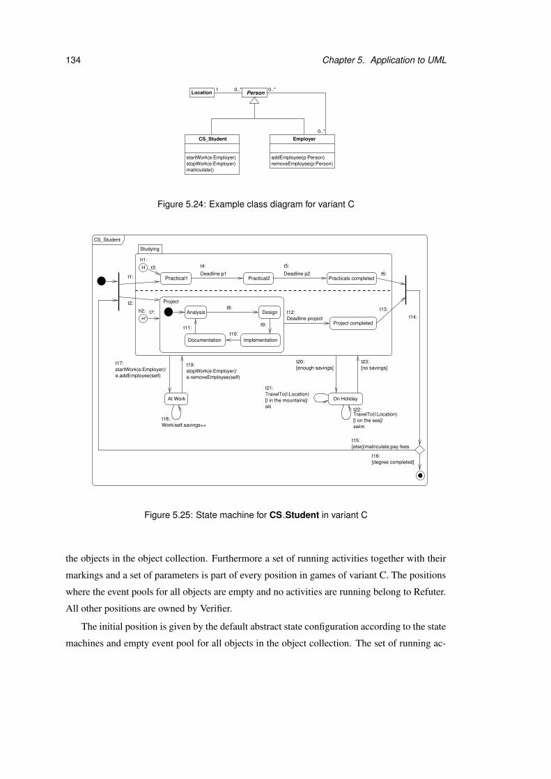
134 Chapter 5. Application to UML
Location Person0..*1 0..*
0..*
startWork(e:Employer)stopWork(e:Employer)
CS_Student Employer
removeEmployee(p:Person)addEmployee(p:Person)
matriculate()
Figure 5.24: Example class diagram for variant C
H*
������������
Studying
Project
h1:
h2:
Project completed
t1:
t2:
CS_Student
e.removeEmployee(self)
[l in the mountains]/ski
[enough savings] [no savings]
[else]/matriculate;pay fees
[degree completed]
t3:
t14:
t13:
t11:t10:
t9:
t8:t7:
t6:
t15:
t16:
startWork(e:Employer)/e.addEmployee(self)
t17: t19:
t18:
t21:
t23:
t22:
t20:
On Holiday
t12:
Documentation Implementation
DesignAnalysis
Practical1 Practicals completedPractical2
At Work
H
stopWork(e:Employer)/
Work/self.savings++
TravelTo(l:Location)
[l on the sea]/swim
TravelTo(l:Location)
Deadline project
Deadline p1
t4:
Deadline p2
t5:
Figure 5.25: State machine for CS Student in variant C
the objects in the object collection. Furthermore a set of running activities together with their
markings and a set of parameters is part of every position in games of variant C. The positions
where the event pools for all objects are empty and no activities are running belong to Refuter.
All other positions are owned by Verifier.
The initial position is given by the default abstract state configuration according to the state
machines and empty event pool for all objects in the object collection. The set of running ac-

5.2. Property checking games 135
Employer
addEmployee(p:Person)
addEmployee(p:Person)
Not enough staff Enough staff
t26:
t27:t24:
t29:removeEmployee(p:Person)
removeEmployee(p:Person)t28:
removeEmployee(p:Person)t25:
addEmployee(p:Person)/p.Work
Figure 5.26: State machine for Employer in variant C
������������������
f17:n12:
Act3: addEmployeep: Person
<<precondition>>: self.employees−>excludes(p)
<<postcondition>>: self.employees−>includes(p)
[worked here before]
p:Person
n14:
Add to Employees
n13:
p:Person
p:Person
Check Employee
Create New
<<context>>: Employer
p
[else]
Records
Employee Record
Figure 5.27: Activity diagram for addEmployee in variant C
tivities and parameter sets are empty. As for variant B the default concrete state configurations
are determined by an instance diagram or from the class diagram where possible.
Figure 5.28 shows the initial position for our example. None
of the classes contains attributes and only the links occur in
the concrete state configurations of the objects. Since there is no in-
stance diagram given which specifies how the objects are linked with
each other, the links are all undefined.
5.2.5.3 Variant C: Moves
At Refuter’s positions By default the game participants can make all moves that were in-
troduced for variant A and B. That means they are allowed to generate events, skip the turn or
invoke activities directly. See Section 5.2.3.3, p.90 and Section 5.2.4.3, p.114 for more detail.
At Verifier’s positions Again the game participants can basically make all moves that have
been introduced for variants A and B. They can fire transitions in the state machines, dis-
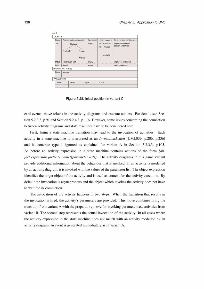
136 Chapter 5. Application to UML
Not enough staffPubXPubX
Italy default
Studying
ProjectPractical1
Analysis
Event poolName
Joe
History mapping
h2:
h1: Practical1
Analysis
Project
empty
empty
p0: R
Abstract state configuration Concrete state configuration
employer=undefined
employee=undefined
location=undefined
Name Marking
empty visitor=undefined
TypeName ValueContext
OBJECTS
RUNNING ACTIVITIES
PARAMETERS
Figure 5.28: Initial position in variant C
card events, move tokens in the activity diagrams and execute actions. For details see Sec-
tion 5.2.3.3, p.91 and Section 5.2.4.3, p.116. However, some issues concerning the connection
between activity diagrams and state machines have to be considered here.
First, firing a state machine transition may lead to the invocation of activities. Each
activity in a state machine is interpreted as an InvocationAction [UML03b, p.206, p.236]
and its concrete type is ignored as explained for variant A in Section 5.2.3.3, p.105.
As before an activity expression in a state machine contains actions of the form [ob-
ject expression.]activity name[(parameter list)]. The activity diagrams in this game variant
provide additional information about the behaviour that is invoked. If an activity is modelled
by an activity diagram, it is invoked with the values of the parameter list. The object expression
identifies the target object of the activity and is used as context for the activity execution. By
default the invocation is asynchronous and the object which invokes the activity does not have
to wait for its completion.
The invocation of the activity happens in two steps. When the transition that results in
the invocation is fired, the activity’s parameters are provided. This move combines firing the
transition from variant A with the preparatory move for invoking parameterised activities from
variant B. The second step represents the actual invocation of the activity. In all cases where
the activity expression in the state machine does not match with an activity modelled by an
activity diagram, an event is generated immediately as in variant A.
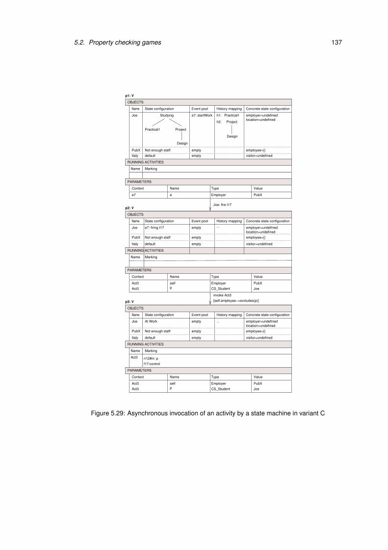
5.2. Property checking games 137
Context
...
Context
[self.employee−>excludes(p)]
invoke Act3
...
n12#in: p
f17:control
Context
Act3
Joe: fire t17
PubXEmployerp CS_Student JoeAct3
Act3 self
PubX Not enough staff empty
Italy default empty
e PubXEmployere7
empty
PubX Not enough staff empty
Italy default empty
empty
PubX Not enough staff empty
Italy default empty
PubXEmployerp CS_Student JoeAct3
Act3 self
State configuration
ProjectPractical1
Design
Event pool
Joe Studying
History mapping
h2:
h1: Practical1
Project
Design
Concrete state configuration
employer=undefinedlocation=undefined
Name Marking
Name ValueType
visitor=undefined
State configuration Event pool
Joe
History mapping Concrete state configuration
employer=undefinedlocation=undefined
Name Marking
Name ValueType
visitor=undefined
State configuration Event pool
Joe
History mapping Concrete state configuration
employer=undefinedlocation=undefined
Name Marking
Name ValueType
visitor=undefined
e7: firing t17
At Work
employee={}
employee={}
employee={}
p1: V
p2: V
p3: V
e7: startWork
PARAMETERS
PARAMETERS
OBJECTS
RUNNING ACTIVITIES
OBJECTS
RUNNING ACTIVITIES
OBJECTS
RUNNING ACTIVITIES
PARAMETERS
Name
Name
Name
Figure 5.29: Asynchronous invocation of an activity by a state machine in variant C
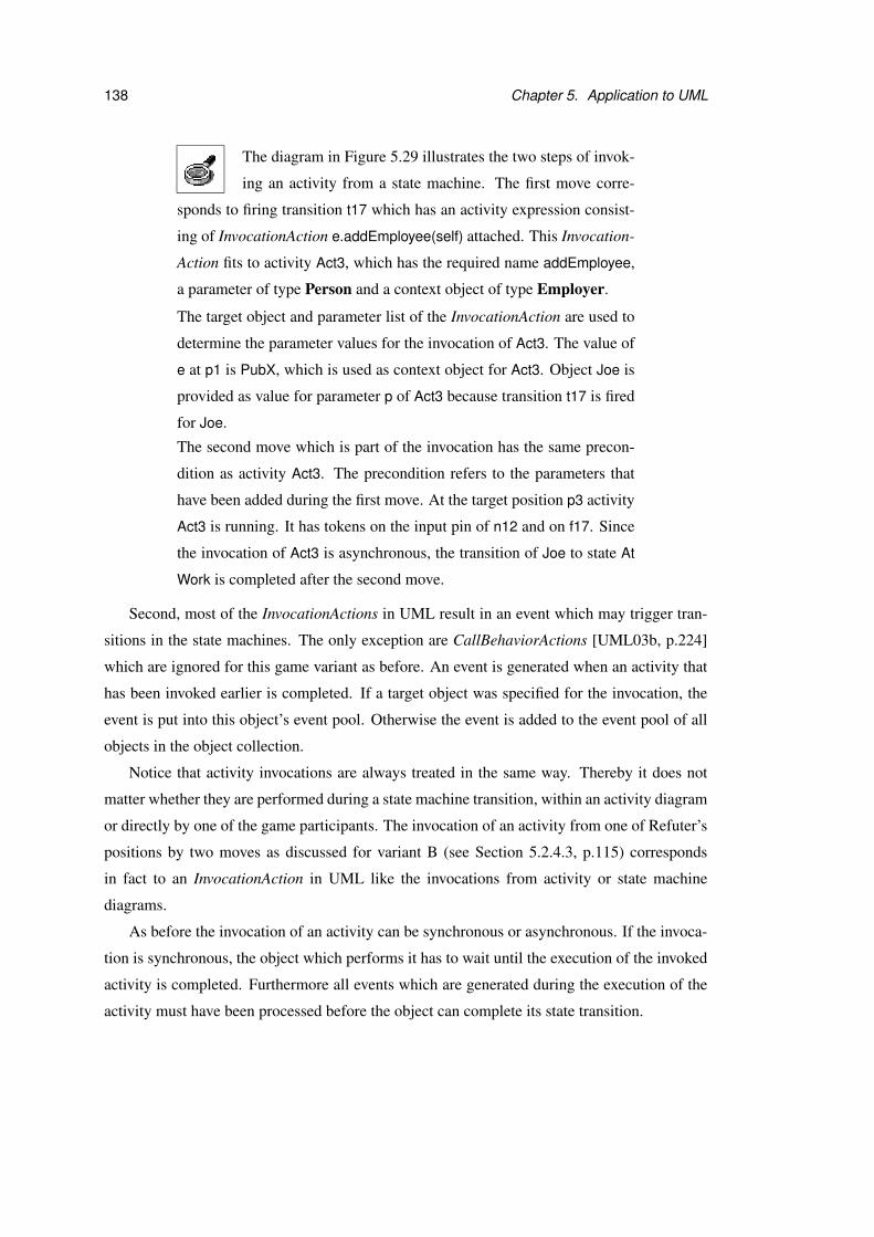
138 Chapter 5. Application to UML
The diagram in Figure 5.29 illustrates the two steps of invok-
ing an activity from a state machine. The first move corre-
sponds to firing transition t17 which has an activity expression consist-
ing of InvocationAction e.addEmployee(self) attached. This Invocation-
Action fits to activity Act3, which has the required name addEmployee,
a parameter of type Person and a context object of type Employer.
The target object and parameter list of the InvocationAction are used to
determine the parameter values for the invocation of Act3. The value of
e at p1 is PubX, which is used as context object for Act3. Object Joe is
provided as value for parameter p of Act3 because transition t17 is fired
for Joe.
The second move which is part of the invocation has the same precon-
dition as activity Act3. The precondition refers to the parameters that
have been added during the first move. At the target position p3 activity
Act3 is running. It has tokens on the input pin of n12 and on f17. Since
the invocation of Act3 is asynchronous, the transition of Joe to state At
Work is completed after the second move.
Second, most of the InvocationActions in UML result in an event which may trigger tran-
sitions in the state machines. The only exception are CallBehaviorActions [UML03b, p.224]
which are ignored for this game variant as before. An event is generated when an activity that
has been invoked earlier is completed. If a target object was specified for the invocation, the
event is put into this object’s event pool. Otherwise the event is added to the event pool of all
objects in the object collection.
Notice that activity invocations are always treated in the same way. Thereby it does not
matter whether they are performed during a state machine transition, within an activity diagram
or directly by one of the game participants. The invocation of an activity from one of Refuter’s
positions by two moves as discussed for variant B (see Section 5.2.4.3, p.115) corresponds
in fact to an InvocationAction in UML like the invocations from activity or state machine
diagrams.
As before the invocation of an activity can be synchronous or asynchronous. If the invoca-
tion is synchronous, the object which performs it has to wait until the execution of the invoked
activity is completed. Furthermore all events which are generated during the execution of the
activity must have been processed before the object can complete its state transition.
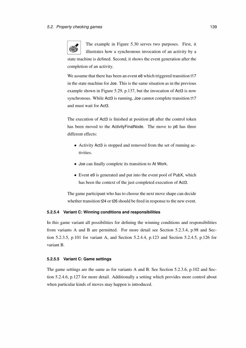
5.2. Property checking games 139
The example in Figure 5.30 serves two purposes. First, it
illustrates how a synchronous invocation of an activity by a
state machine is defined. Second, it shows the event generation after the
completion of an activity.
We assume that there has been an event e8 which triggered transition t17
in the state machine for Joe. This is the same situation as in the previous
example shown in Figure 5.29, p.137, but the invocation of Act3 is now
synchronous. While Act3 is running, Joe cannot complete transition t17
and must wait for Act3.
The execution of Act3 is finished at position p6 after the control token
has been moved to the ActivityFinalNode. The move to p6 has three
different effects:
• Activity Act3 is stopped and removed from the set of running ac-
tivities.
• Joe can finally complete its transition to At Work.
• Event e9 is generated and put into the event pool of PubX, which
has been the context of the just completed execution of Act3.
The game participant who has to choose the next move shape can decide
whether transition t24 or t26 should be fired in response to the new event.
5.2.5.4 Variant C: Winning conditions and responsibilities
In this game variant all possibilities for defining the winning conditions and responsibilities
from variants A and B are permitted. For more detail see Section 5.2.3.4, p.98 and Sec-
tion 5.2.3.5, p.101 for variant A, and Section 5.2.4.4, p.123 and Section 5.2.4.5, p.126 for
variant B.
5.2.5.5 Variant C: Game settings
The game settings are the same as for variants A and B. See Section 5.2.3.6, p.102 and Sec-
tion 5.2.4.6, p.127 for more detail. Additionally a setting which provides more control about
when particular kinds of moves may happen is introduced.
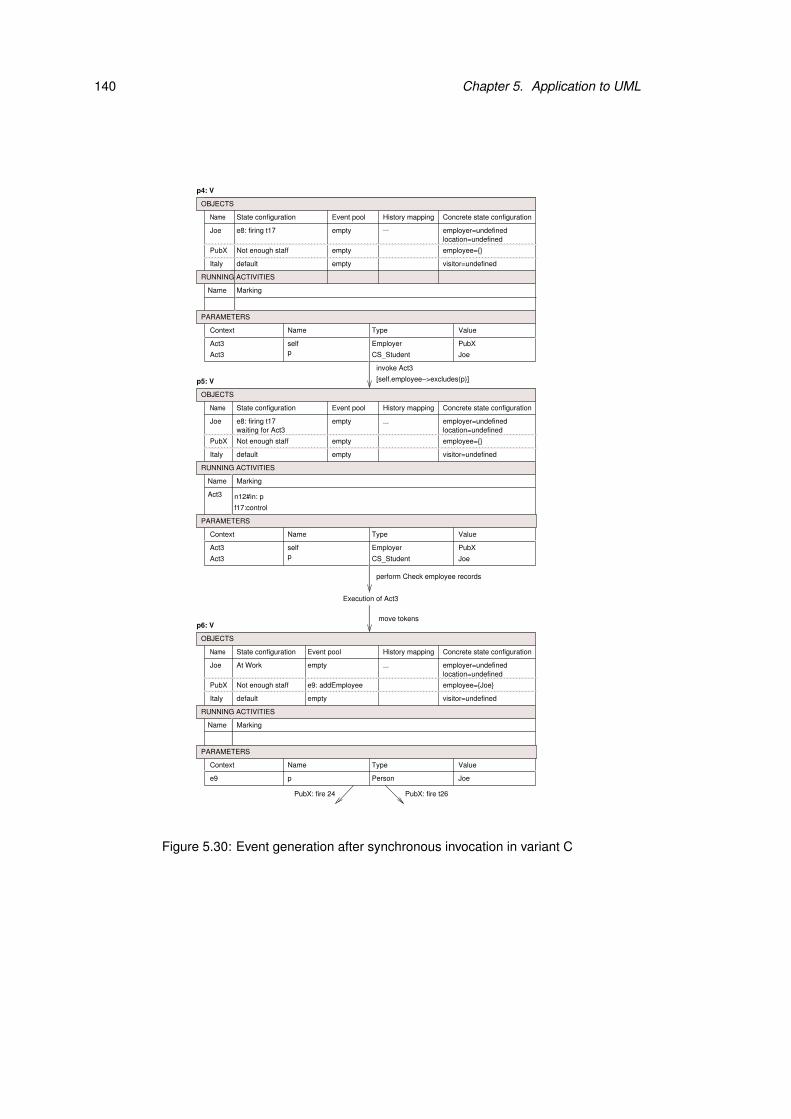
140 Chapter 5. Application to UML
...
Context
invoke Act3
Execution of Act3
...
Context
PubX: fire 24 PubX: fire t26
[self.employee−>excludes(p)]
...
n12#in: p
f17:control
Context
Act3
waiting for Act3
PubXEmployerp CS_Student JoeAct3
Act3 self
empty
PubX Not enough staff empty
Italy default empty
PubXEmployerp CS_Student JoeAct3
Act3 self
PubX Not enough staff
Italy default
empty
empty
e9: addEmployee
move tokens
e9 p Person Joe
empty
PubX Not enough staff empty
Italy default empty
perform Check employee records
State configuration Event pool
Joe
History mapping Concrete state configuration
employer=undefinedlocation=undefined
Name Marking
Name ValueType
visitor=undefined
e8: firing t17
employee={}
State configuration
Joe
History mapping Concrete state configuration
employer=undefinedlocation=undefined
Name Marking
visitor=undefined
At Work
Event pool
employee={Joe}
Name ValueType
State configuration Event pool
Joe
History mapping Concrete state configuration
employer=undefinedlocation=undefined
Name Marking
Name ValueType
visitor=undefined
employee={}
e8: firing t17
p4: V
p5: V
p6: V
PARAMETERS
OBJECTS
RUNNING ACTIVITIES
OBJECTS
RUNNING ACTIVITIES
PARAMETERS
OBJECTS
RUNNING ACTIVITIES
PARAMETERS
Name
Name
Name
Figure 5.30: Event generation after synchronous invocation in variant C
5.2. Property checking games 141
Event and activity priorities (I) At Verifier’s positions the game participant who has to
choose the next move shape may have to decide whether to continue with the execution of
an activity or by dispatching events from the event pools. This situation arises if there is at
least one activity running and at least one event in an event pool. The setting introduced here
can be used to force the game participants to dispatch events or continue with the running
activities first.
• Default: The game participant who chooses the next move shape decides whether an
event is dispatched or the execution of a running activity is continued.
• Event dispatch has higher priority than activity execution. If there is an event in one of
the event pools, it has to be dispatched before the execution of the running activities can
be continued.
• Activity execution has higher priority than event dispatch. If there is an activity running,
it has to be completed first before events can be dispatched from the event pools.
5.2.5.6 Variant C: Incrementations
The Explorer can increment the game as explained for variant A and B. For more detail see
Section 5.2.3.7, p.108 and Section 5.2.4.7, p.130.
5.2.5.7 Variant C: Omitted UML features
None of the features that has been omitted in variant A or B has been considered here. These
features are discussed in Section 5.2.3.8, p.109 and Section 5.2.4.8, p.131. Furthermore this
variant does not cover the relationship between activity diagrams and state machines in detail.
The concrete subclasses of InvocationAction, which connect these two diagram types, have not
been differentiated. If they were considered, a more precise definition of activity invocations by
state machines and event generations after a completed activity execution would be possible.
For example, if the action that invokes an activity is a SendSignalAction [UML03b, p.255],
the UML semantics defines that the invocation is always asynchronous. However, the different
types of InvocationActions are in most cases not distinguished in the UML notation. Even if
such a distinction was supported, it is questionable if a UML modeller would be willing to pay
much attention to the concrete types of InvocationActions.

142 Chapter 5. Application to UML
SUMMARY OF VARIANT C
Prerequisites• Object collection• Class diagram• Set of state machines with class context• Set of activity diagrams• Instance diagram (optional) for the definition of the initial position
Positions• For each object in the object collection
– an abstract state configuration in form of a tree,– an event pool,– a mapping from history pseudostates to state configurations,– a concrete state configuration in terms of the object’s attribute values and links
• A set of running activities and their marking• A set of parameters which are in scope at the position
Moves• Generating an event• Firing a set of enabled transitions• Skipping the turn• Invoking an activity• Executing an action• Moving tokens
Winning conditions• State combinations (abstract and concrete)• Event occurrences• Temporal properties• Invocation order• Action order• Activity markings• Postconditions of activities and actions
Responsibility assignment• Precondition evaluation, choice of move shape: for positions with particular combinations of states
(abstract and concrete) or events; for positions with specific activity markings• Parameter provision: for moves which correspond to the generation of events, invocation of activities or
execution of actions with particular names• Resolution of non-determinism: for moves whose source position contains a specific marking
Incrementations• Add or delete a transition or state• Change a trigger, guard condition or effect at a transition• Add or delete a state machine• Add or delete an operation in the class diagram• Add or delete an activity edge or node• Change the guard condition at an activity edge• Change the pre- and postconditions of actions and activities• Change an action• Add or delete an activity diagram
Figure 5.31: Summary of variant C

5.3. Extensions of property checking games 143
5.3 Extensions of property checking games
In the variants that have been discussed in previous sections, event generations and activity
invocations could be performed in arbitrary order from Refuter’s positions. That means the
system environment has not been restricted so far, which is very uncommon. Most systems are
only required to work correctly for particular usage scenarios.
The question of which environments are relevant for the verification of a system is ad-
dressed in [GPB02]. Therein assumptions about the system under consideration are generated
automatically by an algorithm which has been implemented in the LTSA model checking tool.
This approach requires a formal model of the system in the input language of LTSA.
In the context of UML assumptions are often modelled by sequence diagrams and protocol
state machines. These diagrams often specify not only how a part of the system is used but also
how it is expected to behave under certain circumstances. In this section we demonstrate how
UML diagrams that model system usage and requirements can be used to make a game variant
more precise.
5.3.1 Top-level activity diagrams
A very simple way of modelling the order in which activities have to be performed is to define
one or more toplevel activity diagrams. These diagrams contain actions which invoke activities
in the model and thus determine an invocation order. They can be used to restrict the choice of
activity invocations at Refuter’s positions in variants B and C.
UML does not provide a notation to differentiate between activity diagrams that model the
expected usage of the system and those which model the system’s behaviour. Here we suggest
to add the keyword {toplevel} to the name of toplevel activity diagrams. At Refuter’s positions
the game participants are only allowed to invoke diagrams with this indicator.
5.3.2 Sequence diagrams
A sequence diagram shows which messages are received and sent by a collection of objects
during an interaction. Here we concentrate on sequence diagrams modelling an interaction that
is a desired part of the system’s behaviour5.
Sequence diagrams are often organised hierarchically. As for activity diagrams we assume
that the toplevel sequence diagrams are marked by {toplevel}. The messages in the sequence
5Sequence diagrams can also be used to model undesired error scenarios.

144 Chapter 5. Application to UML
diagrams model event occurrences and can be used to determine the order of event generations
for variants A and C. The objects in the sequence diagrams should be contained in the object
collection for the game that is considered; otherwise the extension by sequence diagrams would
not have an effect.
A pair of sequence diagrams is presented in Figure 5.32. Di-
agram Deadline order is a toplevel sequence diagram which
models the order of deadline messages to the CS Student object Joe.
It contains references to the other diagram After deadline. This diagram
models the interaction between Joe and PubX which takes place after
each deadline. If Joe has enough savings he will go on a skiing holiday,
otherwise he will work for PubX.
ref After deadline
ref After deadline
ref After deadline
m5: ski
m1: Deadline p1
m4: TravelTo(Italy)
Joe:CS_Student Joe:CS_Student PubX:Employer
������������������������������[else]
������������������������������������������������������������������������������������������
sd Deadline order {toplevel}
[enough savings]
m7: addEmployee(Joe)
m9: removeEmployee(Joe)
sd After deadline
alt
m6: startWork(PubX)
m8:stopWork(PubX)
m2: Deadline p2
m3: Deadline project
Figure 5.32: Example sequence diagrams for an extension of Variant A
In a game variant which is extended by sequence diagrams, the execution of the interaction
must be monitored. A simple way to do this is to record the relevant messages and interaction
fragments that have been or are being processed for each diagram in the positions.
Since the purpose of this extension is to restrict the choices at Refuter’s positions, only
messages that are sent by the system environment are considered here. The interactions be-
tween objects in the object collection are ignored. Variant E in Section 5.4.3, p.162, is aimed
at checking whether interactions modelled by sequence diagrams can be realised by the objects
that participate in them.

5.3. Extensions of property checking games 145
If there is no toplevel sequence diagram running at a position owned by Refuter, one may
be invoked. By this move the diagram is added to the running sequence diagrams. Thereafter
the game participants have to follow the execution of this toplevel diagram at all subsequent
positions which belong to Refuter. If a message from the system environment is sent to an
object in the object collection, a corresponding event is generated during the same move. The
event is put into the event pool of the object that is the target of the message in the sequence
diagram. The arguments of the message have to be used as parameter values for the generated
event, if they can be resolved to concrete values or objects. For all parameters where the values
are not specified by the message arguments, the responsible game participant has to provide
suitable values.
When the next position of Refuter is reached, the last generated event and all interactions
caused by it have been processed. At this point the game participants have to continue the
play by sending the next message from the system environment as modelled by the sequence
diagrams.
The InteractionFragments [UML03b, p.422] in sequence diagrams are executed according
to the UML semantics. There are several kinds of InteractionFragments. Here we consider
InteractionOccurrences [UML03b, p.423] and CombinedFragments [UML03b, p.409] with
the InteractionOperator [UML03b, p.426] alt as examples.
For InteractionOccurrences the toplevel sequence diagram is continued by the interaction
which the InteractionOccurrence refers to. If this interaction is modelled by a sequence di-
agram, the execution of this diagram is monitored. When the interaction is completed, the
execution of the toplevel diagram is continued after the InteractionOccurrence.
If a CombinedFragment with an alt operator is reached, each possible continuation of the
message sequence is represented by a move. Each move corresponds to sending the first mes-
sage of one of the alternative fragments. The guards of the operand are used as preconditions
for these moves. The subsequent moves consist of sending messages from the system environ-
ment as modelled by the chosen fragment.
Assume that the sequence diagrams in Figure 5.32 are used to
extend the example game for variant A which was presented
in Section 5.2.3, p.86. Figure 5.33 shows a move sequence in the ex-
tended game.
146 Chapter 5. Application to UML
From position p0 the game participants can invoke Deadline order which
is the only toplevel sequence diagram in the set. After this invocation
the first message m1 is sent and a corresponding event is put into the
event pool of target object Joe.
The letter T in brackets after the sequence diagram name indicates that
Deadline order is the toplevel sequence diagram. A more detailed dia-
gram with the moves from position p0 to p2 is discussed for variant E
(see Figure 5.47 in Section 5.4.3, p.166).
At position p2 the game participants react to event Deadline p1 as usual.
When all event pools are empty again at position p3, the execution of
Deadline order must be continued by the referenced sequence diagram
After deadline. This diagram offers two alternatives: the sequence is ei-
ther continued by m4 or by m6. Each of these possibilities is represented
by a move from p3. The moves have the preconditions that are specified
as guard conditions in sequence diagram After deadline.
5.3.3 Protocol state machines
Protocol state machines provide usage protocols for classifiers. They show the permitted or-
der in which events may arrive and can also specify pre- and postconditions. Extension by
protocol state machines is possible for variants A and C. It involves adding protocol state con-
figurations to the variant’s position, which are the same as the abstract state configurations for
variant A (see Section 5.2.3.2, p.88) except that they refer to protocol state machines instead
of behavioural state machines. If the protocol state machine contains history pseudostates, the
history mapping must be extended such that it maps these pseudostates to suitable protocol
state configurations.
With this additional information it is possible to determine which events violate the proto-
col at Refuter’s positions and to reduce the number of outgoing moves accordingly. We first
consider the generation of call events that are targeted at a particular object. If there exists a
protocol state machine for an object, each call event that requires an object of this type and
whose name occurs as trigger at a protocol transition from the current protocol state configura-
tion may be generated. A parameterised call event is generated in two consecutive moves. In
the first move the event parameters are provided. The intermediate position which is reached
after this move belongs to Refuter because no event has yet been added to the event pools. If no

5.3. Extensions of property checking games 147
......
... ...
...
... ... ... ...
...
............
Deadline order (T)
... ... ... ...
invoke Deadline order
......
...
Deadline order (T)
...
...
m1
... ... ... ...
......
...
Deadline order (T)
...
...
m1; After deadline
......
...
Deadline order (T)
...
...
m1; After deadline
...
............
Deadline order (T)
... ... ... ...
Name
Name State configuration
Executed parts
Joe
Event pool History mapping
emptyempty
p0: R
Name
Name State configuration
Joe
Event pool History mapping
emptyempty
Executed parts
p1: R
p3: R
Name
Name State configuration
Joe
Event pool
empty
Executed parts
History mapping
p2: V
Deadline p1
Name
Name State configuration
Joe
Event pool
empty
Executed parts
History mapping
p4: V
Name
Name
Joe
Executed parts
History mapping
p5: V
State configuration Event pool
e2: startWorkempty
Name
Name State configuration
Joe
Event pool History mapping
emptyempty
Executed parts
e1: TravelTo
PARAMETERS
OBJECTS
RUNNING SEQUENCE DIAGRAMS
PARAMETERS
OBJECTS
RUNNING SEQUENCE DIAGRAMS
PARAMETERS
Context Name Type Value
e1 l Location Italy
After deadline
PARAMETERS
m6
Context Name Type Value
e Employer PubXe2
Deadline order:m1
PARAMETERS
OBJECTS
RUNNING SEQUENCE DIAGRAMS
Processing of Deadline p1
[enough savings]
OBJECTS
RUNNING SEQUENCE DIAGRAMS
After deadline: m4
OBJECTS
RUNNING SEQUENCE DIAGRAMS
[else]After deadline: m6
After deadline m4
m1
PARAMETERS
OBJECTS
RUNNING SEQUENCE DIAGRAMS
Figure 5.33: Example moves in an extension of variant A by sequence diagrams
148 Chapter 5. Application to UML
protocol transition can be fired from this position, the play is finished. The preparatory move
is left out if the event does not have any parameters. In the second move a protocol transition
which has the desired call event as trigger is fired. At the same time a new call event is gener-
ated and put into the event pool of the target object. The precondition of this move is given by
the precondition of the protocol transition which is fired.
For the generation of a signal event all objects must be in a protocol state configuration
where they are allowed to receive the desired signal event, or their protocol state machine must
not contain the signal event at all. In the latter case the event is assumed to have no effect on
the state of objects of this class [UML03b, p.469]. The preparatory move during which the
event parameters are provided is the same as for call events. In the second move of the event
generation a protocol transition must be fired for each object with a protocol state machine
that contains the event. The new event is added to the event pools of all objects in the object
collection. The precondition of the move is given by the conjunction of all preconditions of the
protocol transitions that are fired.
Additionally the game participants may also generate events for all operations that appear
in a class of the class diagram, but not in the class’s protocol state machine. This coincides
with the UML semantics for unreferred operations [UML03b, p.469]. The generation of skip
events, which has been discussed in Section 5.2.3.3, p.96, is also still possible. For all objects
without a protocol state machine configuration events may be generated in arbitrary order as
before. Notice that the protocol state machines may contain transitions which are not realised
by the behavioural state machines. Realisability will be discussed in Section 5.4.3, p.162 for
variant D.
Figure 5.34 shows a protocol state machine for CS Student.
This diagram is used to extend the game that has been dis-
cussed for variant A (see Section 5.2.3, p.86). Some positions and
moves of the extended game are presented in Figure 5.35.
The protocol state machine configuration (abbreviated by “PS configu-
ration” in the figure) for Joe only permits the generation of startWork,
Deadline p1 and TravelTo at position p6. The last event is a signal event
and may be generated because it does not occur in the protocol state
machine for CS Student. For PubX the game participants are still al-
lowed to generate addEmployee or removeEmployee, because there is
no protocol state machine defined for Employer.

5.3. Extensions of property checking games 149
2nd term 3rd term
stopWorkpt5:
At Work
CS_Student {protocol}
pt6: pt7:
pt1: pt2: pt3:
1st term
[practical 1 completed]startWork(e:Employer}/[self employed by e]
pt4:
courseworkcompleted
Abroad
Deadline p1 Deadline p2 Deadline project
GoOnHoliday ReturnFromHoliday
Figure 5.34: Protocol state machine for CS Student for an extension of Variant A
Joe: fire pt4[practical 1 completed]
default
Not enough staffPubX
Italy
default
Not enough staffPubX
Italy
default
Not enough staffPubX
Italy
PS configuration
...
...
...addEmployee(Joe)
Joe.startWork(PubX)
PubX Not enough staff
Italy default
removeEmployee(Joe)
TravelTo(Italy)
Deadline p1
Deadline p1
Deadline p1
Deadline p1
p9: V
Name
Joe
Context
startWork
Name
e
Value
PubX
Type
Employer
p7: R
... ... ...
State configuration Event pool History mapping PS configuration
1st term
State configurationName
Joe
Event pool
...
History mapping PS configuration
... At Work
Context
e10
Value
PubX
Type
Employer
Name
e
State configuration
Studying
ProjectPractical1
Analysis
Event poolName
Joe
Analysis
Project
empty
empty
empty
History mapping
Practical1h1:
h2:
Context Type ValueName
1st term
p6: R
Name
Joe
Event poolState configuration History mapping
...
PS configuration
2nd term
Context ValueTypeName
...
p8: V
empty
empty
empty
empty
OBJECTS
PARAMETERS
OBJECTS
e10: startWork
PARAMETERS
OBJECTS
PARAMETERS
OBJECTS
e11:
e11:
e11:
PARAMETERS
Figure 5.35: Example moves in an extension of variant A by protocol state machines

150 Chapter 5. Application to UML
If startWork is selected, the move to position p7 only stores the param-
eter for the event. The following move to p9 consists of firing protocol
transition pt4 for Joe and generating the new event e10 with the pa-
rameter that has been provided before. Its precondition is given by the
precondition at pt4. In case of signal event Deadline p1 no intermediate
positions are needed, because the event is not parameterised.
The protocol state machine for CS Student contains two additional
events GoOnHoliday and ReturnFromHoliday which are not realised by
the behavioural state machine, but may be generated by the game par-
ticipants at positions with suitable protocol state configurations. Under
the default game settings these events will be discarded in the next move
immediately after their creation because they do not trigger a transition
in the behavioural state machine.
An extension of a game variant by protocol state machines may also make the game more
difficult to win for Verifier. The usage protocol which is defined by a protocol state machine
does not only have to be respected by the environment, but also by the system itself. In contrast
to sequence diagrams, which were used as extension in Section 5.3.2, protocol state machines
define all possible event sequences for one classifier.
In variants A and C new events may be generated while a transition is fired or when an
activity is completed. These events may trigger further transitions in the behavioural state
machines. When an object performs a transition that has been triggered in such a way at one
of Verifier’s positions, a protocol transition with the same trigger must be fired if there exists
a protocol state machine for the object. The protocol transition is fired in the same move
during which the transition in the behavioural state machine is performed. The precondition of
this move is given by the conjunction of the protocol transition’s precondition and the guard
condition of the transition in the behavioural state machine. If there is a protocol state machine
defined for the object that changes its state, but there exists no suitable protocol transition, the
protocol has been violated and Verifier loses the play. This condition is an implicit part of the
winning condition for Refuter. If there is no protocol state machine specified for an object, the
transitions which are fired at Verifier’s positions do not have to respect this condition..
Furthermore protocol state machines may contain postconditions at the transitions which
constitute parts of the system requirements. These requirements can again be interpreted as
winning conditions for Refuter. The postcondition at a protocol transition must hold when

5.3. Extensions of property checking games 151
the next position belonging to Refuter is reached after the transition has been fired. If the
postcondition is violated, Refuter wins the play.
If the extension mechanism presented here is applied to variant A, it is often difficult
to evaluate the winning conditions because the positions do not contain much information.
The general game setting regarding undefined evaluation of the winning conditions (see Sec-
tion 5.1.3, p.83) is very important in this case.
Consider an additional protocol state machine for Employer
as shown in Figure 5.36. The protocol state machine specifies
that a call of removeEmployee is not permitted for an Employer object
in state Not enough staff. In the move sequence presented in Figure 5.37
this requirement is violated when the effect at t19 is performed.
Employer {protocol}
addEmployee(p:Person)
addEmployee(p:Person)
Not enough staff Enough staff
removeEmployee(p:Person)
removeEmployee(p:Person)
pt8:addEmployee(p:Person)
pt9:
pt10:
pt11:
pt12:
Figure 5.36: Protocol state machine for Employer for an extension of variant A

152 Chapter 5. Application to UML
default
Not enough staffPubX
Italy
e11 e PubXEmployer
default
Not enough staffPubX
Italy
e12
VIOLATED
Person Joep
Joe: fire t19
State configurationName
Joe
Context
At Work
Event pool
empty
empty
Analysis
Project
Practical2
Not enough staff
Name Value
At Work
Type
State configurationName
Joe
Context
Event pool
empty
Project
Studying
Practical2
Analysis
Analysis
Project
h1:
h2:
Practical2
History mapping PS configuration
e12: removeEmployee
empty 1st term
Type ValueName
p10: V
p11: V
e11: stopWork
PS configurationHistory mapping
h1:
h2:
OBJECTS
PARAMETERS
OBJECTS
PARAMETERS
Figure 5.37: Protocol violation in an extension of variant A by protocol state machines

5.4. Comparison games 153
5.4 Comparison games
This section introduces a different category of games which aim at the comparison of UML
diagrams or models. Here we concentrate on game variants which compare two behavioural
diagrams. Games of this kind can be used for “sanity checks” whether the desired function-
ality is realised by a design in UML. Two variants which fulfil this purpose are introduced in
Section 5.4.2 and Section 5.4.3. A game variant which compares behavioural aspects of two
design alternatives is discussed in Section 5.4.4.
5.4.1 Comparison games: Winning conditions
The games in this category all have a very simple winning condition in common: a player
wins if a dead end position of his opponent is reached. This winning condition applies to
both players and corresponds to the general winning condition dead end position of opponent
reached which can be used for all game variants and was introduced in Section 5.1.1, p.80. As
usual this kind of winning condition can be combined with other winning conditions.
The game variants which are presented in this section do not provide any additional variant
specific types of winning conditions. However, we will explain the meaning of reaching dead
end positions and give some examples of plays and winning strategies for each variant.
5.4.2 Variant D: Protocol realisability
According to the UML semantics protocol conformance between a behavioural and a protocol
state machine means that the behavioural state machine implements the protocol state machine
and respects all its rules and constraints [UML03b, p.464]. One aspect of this conformance
is that the behavioural state machine must be able to perform transitions as defined by the
protocol state machine under the specified preconditions. The protocol state machine defines a
set of possible event sequences which must be realised by the behavioural state machine. The
aim of this game variant is to check this notion of realisability.
5.4.2.1 Variant D: Prerequisites
The game is based on a behavioural state machine and a protocol state machine with the same
class context. The execution of the state machines is considered for one anonymous object of
this class and an object collection is not required.
154 Chapter 5. Application to UML
As example for this game variant we consider a slightly modi-
fied version of the behavioural state machine for CS Student
and the protocol state machine for this class which has been introduced
before. The two state machines are shown in Figure 5.38 and Fig-
ure 5.39. The behavioural state machine differs from the previous ver-
sion in that it has two additional guard conditions at transitions t17 and
t19.
[has no time for work][has time for work]
H*
������������
Studying
Project
h1:
h2:
Project completed
t1:
t2:
CS_Student
[l in the mountains]/ski
[enough savings] [no savings]
[else]/matriculate;pay fees
[degree completed]
t3:
t14:
t13:
t11:t10:
t9:
t8:t7:
t6:
t15:
t16:
t17: t19:
t18:
t21:
t23:
t22:
t20:
On Holiday
t12:
Documentation Implementation
DesignAnalysis
Practical1 Practicals completedPractical2
At Work
H
startWork(e:Employer)
e.removeEmployee(self)e.addEmployee(self)
stopWork(e:Employer)/
Deadline project
Work/self.savings++
TravelTo(l:Location)
[l on the sea]/swim
TravelTo(l:Location)
Deadline p1
t4:
Deadline p2
t5:
Figure 5.38: State machine for CS Student in variant D
5.4.2.2 Variant D: Positions
The positions contain the configurations of the behavioural and protocol state machine. They
also provide a history mapping for the two state machines. History mappings have already been
discussed for variant A in Section 5.2.3.2, p.88. The history pseudostates in the behavioural
state machine are mapped to state configurations as usual, and for each history pseudostate in a
protocol state machine a protocol state configuration is recorded. Moreover the positions con-
5.4. Comparison games 155
2nd term 3rd term
stopWorkpt5:
At Work
CS_Student {protocol}
pt6: pt7:
pt1: pt2: pt3:
1st term
[practical 1 completed]startWork(e:Employer}/[self employed by e]
pt4:
courseworkcompleted
Abroad
Deadline p1 Deadline p2 Deadline project
GoOnHoliday ReturnFromHoliday
Figure 5.39: Protocol state machine for CS Student in variant D
tain the last protocol trigger which caused the last protocol transition and still has to be handled
for the behavioural state machine. Refuter owns all positions where no last protocol trigger is
recorded, Verifier all remaining positions. Notice that there is no need to store parameters in the
positions because the moves in this variant are not parameterised. The initial position contains
the default configurations of the two state machines and its last protocol trigger is empty.
Figure 5.40 shows the initial position for our example. The
position contains the default configurations of the behavioural
and protocol state machine for CS Student. The history mapping maps
the two history nodes in the behavioural state machine to subtrees of the
default state configuration. There is no history recorded for the protocol
state machine because it does not contain any history pseudostates. The
part of the position where the last protocol trigger is recorded is empty.
p0: R
State configuration PS configuration
1st termStudying
ProjectPractical1
Analysis
h1: Practical1
h2: Project
Analysis
History mapping
CONFIGURATIONS
LAST PROTOCOL TRIGGER
Figure 5.40: Initial position in variant D
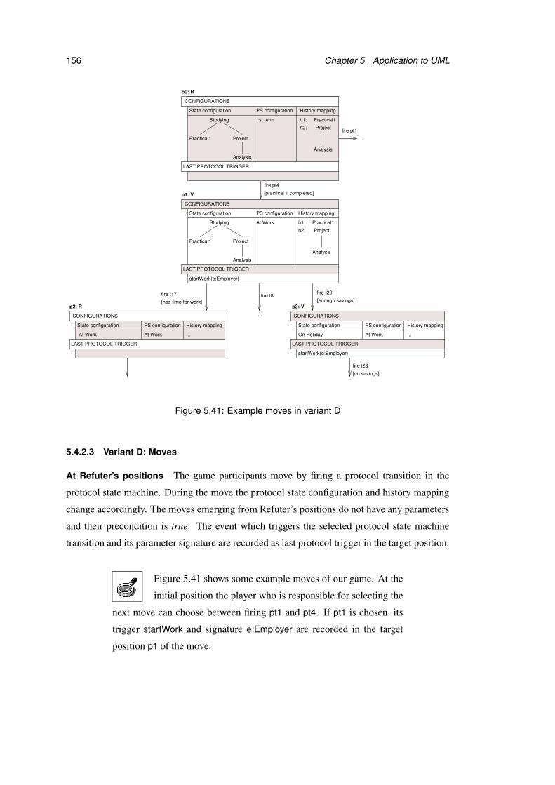
156 Chapter 5. Application to UML
...
..
fire pt1
...
fire t23
...
fire t20
...
Studying
ProjectPractical1
Analysis
Studying
ProjectPractical1
Analysis
h1: Practical1
h2: Project
Analysis
h1: Practical1
h2: Project
Analysis
History mappingState configuration PS configuration
At WorkAt Work
p2: R
...
[has time for work]
fire t17
p0: R
State configuration PS configuration
1st term
State configuration PS configuration
p1: V
At Work
startWork(e:Employer)
History mapping
History mapping
History mappingState configuration PS configuration
At WorkOn Holiday
startWork(e:Employer)
[no savings]
p3: V[enough savings]
fire pt4
[practical 1 completed]
fire t8
CONFIGURATIONS
LAST PROTOCOL TRIGGER
CONFIGURATIONS
LAST PROTOCOL TRIGGER
CONFIGURATIONS
LAST PROTOCOL TRIGGER
LAST PROTOCOL TRIGGER
CONFIGURATIONS
Figure 5.41: Example moves in variant D
5.4.2.3 Variant D: Moves
At Refuter’s positions The game participants move by firing a protocol transition in the
protocol state machine. During the move the protocol state configuration and history mapping
change accordingly. The moves emerging from Refuter’s positions do not have any parameters
and their precondition is true. The event which triggers the selected protocol state machine
transition and its parameter signature are recorded as last protocol trigger in the target position.
Figure 5.41 shows some example moves of our game. At the
initial position the player who is responsible for selecting the
next move can choose between firing pt1 and pt4. If pt1 is chosen, its
trigger startWork and signature e:Employer are recorded in the target
position p1 of the move.
5.4. Comparison games 157
At Verifier’s positions Each move emerging from Verifier’s positions involves firing a tran-
sition in the behavioural state machine. The target position of the move contains the new state
configuration and history mapping. Effects at transitions are ignored for this game variant. The
transition that is fired either has to fit the last protocol transition, or must have an empty trigger.
In the first case the last protocol trigger is removed and the target position of the move belongs
to Refuter. If a transition with an empty trigger is chosen, the last protocol trigger remains in
the play, because its realisability has not yet been demonstrated. In this case the target position
is owned by Verifier, who still has to find a way to respond appropriately to the last protocol
trigger.
The precondition of each move is given by the guard condition of the fired transition. As
usual the move’s precondition is evaluated over the play history, which is particularly important
for this game variant. The play history contains information about which protocol transition
has been fired last. The precondition for firing this transition must have been evaluated to true,
because otherwise this move would have been illegal. This knowledge about the precondition
of the last protocol transition can be very useful for evaluating the precondition for firing the
matching transition in the behavioural state machine since both state machines refer to the same
anonymous object.
As shown in Figure 5.41, there are three possibilities to re-
act to protocol transition pt4. From position p1 transition t17
whose trigger matches the last protocol trigger may be fired. Alterna-
tively t8 or t20 can be selected because their triggers are empty.
The precondition of the move which corresponds to firing t17 is has
time for work. The precondition of the last fired protocol transition pt4
was practical 1 completed. The question that has to be answered by
the evaluation of the move’s precondition is whether a student that has
completed practical 1 has time for work. Normally a judgement like this
cannot be automated and has to be made by the human designer.
5.4.2.4 Variant D: Winning conditions
A play of this game variant is won by Refuter if there is no adequate response to a protocol
transition. Similarly Verifier wins if Refuter cannot fire another protocol transition to challenge
her.
158 Chapter 5. Application to UML
Assume that the game is played with the default responsibil-
ities and Refuter challenges by firing protocol transitions pt1,
pt2, pt3 and pt6. Even though there is no behavioural transition which
matches the trigger goOnHoliday at pt6 Verifier can win this play. She
can respond by firing t4, t5 and t12 to Refuter’s first three challenges.
After that she may react to pt6 by firing t20 and t21 with empty triggers
alternately. In order to do this she must always evaluate the precondi-
tions of these moves to true. She can continue this procedure infinitely
and never proves that pt6 is realised by the behavioural state machine.
Another cycle of transitions with empty triggers that can be used for
the purpose of escaping the obligation to prove realisability consists of
transitions t8, t9, t10 and t11. If Refuter challenges by pt4, Verifier can
respond by firing this cycle infinitely. Thereby she avoids having to find
a matching transition in the behavioural state machine.
A solution to this problem is to introduce a move limit and to define that
Verifier loses the play if the limit is reached. Another possibility is to
forbid firing transitions with empty triggers in cycles by changing the
game settings as described below in Section 5.4.2.6, p.160.
For transitions with empty triggers that have guard conditions, like t20
and t21, the responsibilities of the game can be changed such that Veri-
fier cannot always evaluate the preconditions for firing to true. However,
Verifier may still be able to fire other cycles of transitions with empty
triggers and no guard conditions, like t8, t9, t10, t11, in this case.
If there is a move limit defined and Refuter challenges by pt4, it depends
on the precondition evaluation whether Verifier loses the play or if the
play may continued. If the condition has time for work is evaluated to
true, Verifier can fire transition t17. Otherwise she cannot move and
Refuter wins the play.
Notice that this game variant is focused on checking whether a behavioural transition that
matches the last protocol transition can be fired. The effect of a behavioural transition on
the object states is ignored and the postconditions at the protocol transitions are irrelevant. If
postconditions were considered, Refuter would win all plays where the postcondition of the

5.4. Comparison games 159
Responsibility Verifier Refuter Referee
Precondition evaluation None last protocol trigger: Remaining
startWork(e:Employer)
Choice of move shape Remaining State configuration: None
Project
Table 5.4: Example assignment of responsibilities for variant D
last fired protocol transition does not hold after Verifier has fired a matching transition in the
behavioural state machine. The evaluation of the winning conditions would be difficult in
this case, because the positions of the game contain very little information. In contrast to the
evaluation of preconditions, the play history would not be helpful for this kind of evaluation.
Thus the outcome of the evaluation would often be undefined, and – depending on the game
settings – either be ignored or corrected by the Referee. Extending a property checking game
variant by protocol state machines as introduced in Section 5.3.3, p.146, is a more sensible
approach to checking the postconditions in a protocol state machine because there the positions
contain more information.
5.4.2.5 Variant D: Responsibilities
The only responsibilities that are relevant for this game variant are the evaluation of precondi-
tions and selection of move shapes. Since none of the moves is parameterised and the arena
of the game is deterministic, the other two responsibilities can be omitted. The responsibilities
can be assigned by defining state or protocol state combinations. Furthermore responsibilities
may be specified by referring to the last protocol trigger in the positions.
Table 5.4 shows example responsibilities for this game vari-
ant. Notice that a state at any level of the state hierarchy can
be used in the definition of a responsibility. In this example Project is
used as reference for defining the responsibility of selecting the next
move shape for Refuter.
160 Chapter 5. Application to UML
5.4.2.6 Variant D: Game settings
Firing of transitions with empty triggers (I) As discussed in Section 5.4.2.4, p.157, it is
often desirable to forbid infinite cycles of transitions with empty triggers.
1. Default: A transition with an empty trigger may be fired if the precondition for firing the
transition is evaluated to true and its source state is in the current state configuration.
2. A transition with an empty trigger may only be fired if it has not already been fired since
the last position of Refuter has been visited.
If infinite cycles of transitions with empty triggers are forbid-
den, Verifier may only fire one cycle of the sequences t8, t9,
t10, t11 and t20, t21 each. After she has fired both cycles of transitions
one time she is forced to respond to the last protocol trigger.
5.4.2.7 Variant D: Incrementations
The Explorer can increment the game by the following moves in variant D:
• Add or delete a transition or protocol transition between two existing states or protocol
states.
• Add or delete a state or protocol state. All transitions which point to or emerge from the
deleted state are also deleted.
• Change the trigger or guard condition at a transition in the behavioural state machine.
• Change the precondition or trigger at a protocol transition.
5.4.2.8 Variant D: Omitted UML features
The same features of state machines that have been omitted for variant A have also been omitted
here. For more detail see Section 5.2.3.8, p.109.
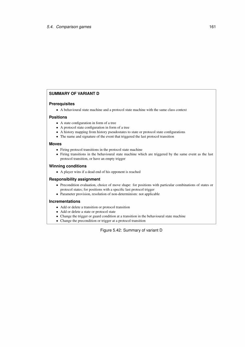
5.4. Comparison games 161
SUMMARY OF VARIANT D
Prerequisites• A behavioural state machine and a protocol state machine with the same class context
Positions• A state configuration in form of a tree• A protocol state configuration in form of a tree• A history mapping from history pseudostates to state or protocol state configurations• The name and signature of the event that triggered the last protocol transition
Moves• Firing protocol transitions in the protocol state machine• Firing transitions in the behavioural state machine which are triggered by the same event as the last
protocol transition, or have an empty trigger
Winning conditions• A player wins if a dead end of his opponent is reached
Responsibility assignment• Precondition evaluation, choice of move shape: for positions with particular combinations of states or
protocol states; for positions with a specific last protocol trigger• Parameter provision, resolution of non-determinism: not applicable
Incrementations• Add or delete a transition or protocol transition• Add or delete a state or protocol state• Change the trigger or guard condition at a transition in the behavioural state machine• Change the precondition or trigger at a protocol transition
Figure 5.42: Summary of variant D

162 Chapter 5. Application to UML
5.4.3 Variant E: Sequence realisability
In this game variant sequence diagrams express the desired behaviour of the system, while
state machines are used to model the actual behaviour of the system’s components. The goal
of playing the game is to check whether the interactions described by the sequence diagrams
can be realised by the state machines. This game variant is strongly related to variant A and
its extension by sequence diagrams which have been presented in Section 5.2.3, p.86 and Sec-
tion 5.3.2, p.143. All messages in the sequence diagrams are considered here, not only those
which are sent by the environment as in Section 5.3.2.
Realisability of sequences has already been discussed in the context of UML model check-
ing tools in Section 2.5.2. Work in this direction is, for example, presented in [KM02] and
[IMP01]. These approaches differ from our exploration games in that the user may not resolve
uncertain situations or increment the design model during the verification process.
5.4.3.1 Variant E: Prerequisites
The game is based on an object collection, a set of sequence diagrams, which must contain
at least one toplevel diagram, and a set of behavioural state machines. The object collection
consists of all objects that occur as participants or message arguments in the sequence diagrams.
For this game variant we consider the sequence diagrams
from Section 5.3.2 as example. They are shown again
in Figure 5.43. The object collection contains Joe:CS Student,
PubX:Employer and Italy:Location. The state machines for
CS Student and Employer have already been used as example in pre-
vious variants and are shown again in Figure 5.44 and Figure 5.45.
5.4.3.2 Variant E: Positions
The definition of positions for this game variant is the same as for variant A extended by se-
quence diagrams, which has been described in Section 5.3.2, p.143. For all objects in the
object collection the positions contain state configurations, event pools and history mapping.
They also record the current execution state of all sequence diagrams by specifying the mes-
sages and interaction fragments that have been or are being processed. Moreover the positions
specify which parameters are in scope. The positions where the event pools of all objects are

5.4. Comparison games 163
ref After deadline
ref After deadline
ref After deadline
m5: ski
m1: Deadline p1
m4: TravelTo(Italy)
Joe:CS_Student Joe:CS_Student PubX:Employer
������������������������������[else]
������������������������������������������������������������������������������������������
sd Deadline order {toplevel}
[enough savings]
m7: addEmployee(Joe)
m9: removeEmployee(Joe)
sd After deadline
alt
m6: startWork(PubX)
m8:stopWork(PubX)
m2: Deadline p2
m3: Deadline project
Figure 5.43: Example sequence diagrams for variant E
[has no time for work][has time for work]
H*
��������
Studying
Project
h1:
h2:
Project completed
t1:
t2:
CS_Student
[l in the mountains]/ski
[enough savings] [no savings]
[else]/matriculate;pay fees
[degree completed]
t3:
t14:
t13:
t11:t10:
t9:
t8:t7:
t6:
t15:
t16:
t17: t19:
t18:
t21:
t23:
t22:
t20:
On Holiday
t12:
Documentation Implementation
DesignAnalysis
Practical1 Practicals completedPractical2
At Work
H
startWork(e:Employer)
e.removeEmployee(self)e.addEmployee(self)
stopWork(e:Employer)/
Deadline project
Work/self.savings++
TravelTo(l:Location)
[l on the sea]/swim
TravelTo(l:Location)
Deadline p1
t4:
Deadline p2
t5:
Figure 5.44: State machine for CS Student in variant E
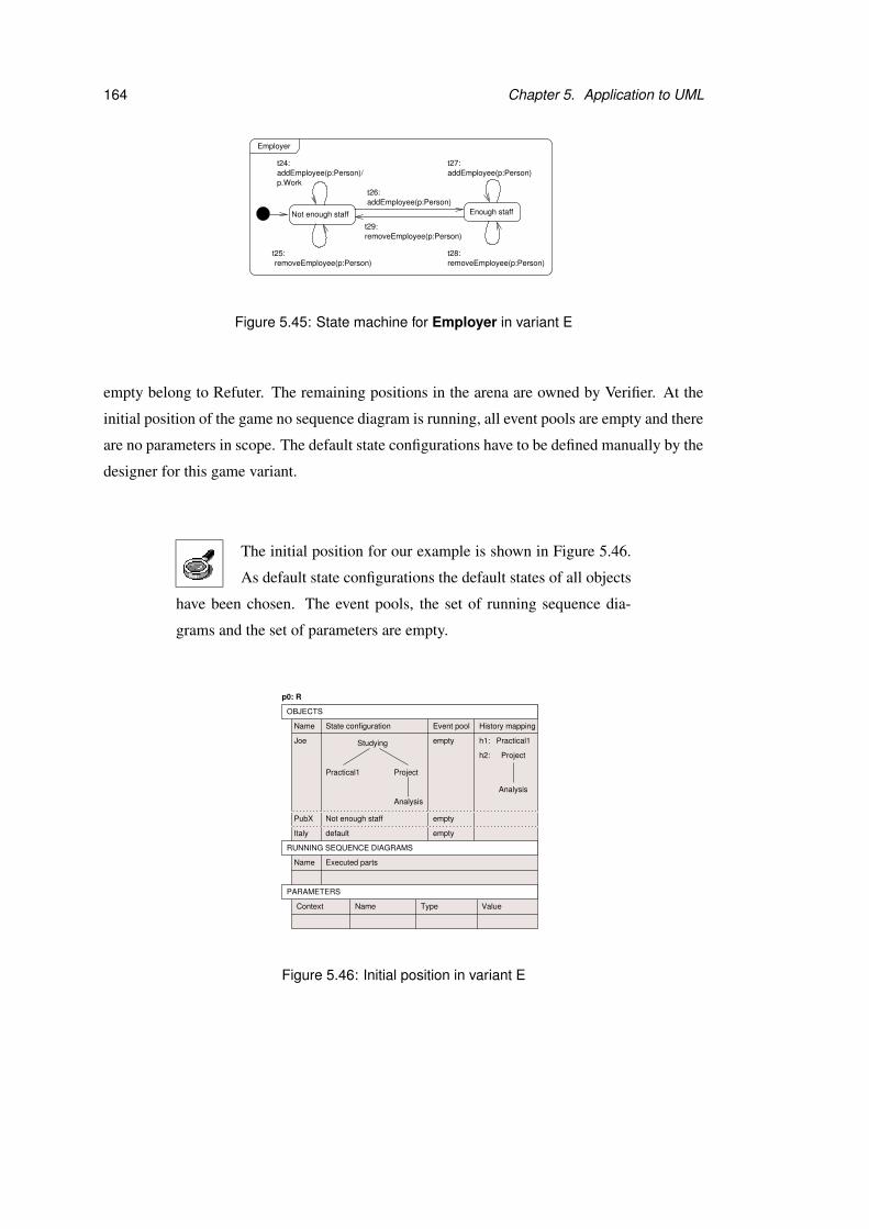
164 Chapter 5. Application to UML
Employer
addEmployee(p:Person)
addEmployee(p:Person)
Not enough staff Enough staff
t26:
t27:t24:
t29:removeEmployee(p:Person)
removeEmployee(p:Person)t28:
removeEmployee(p:Person)t25:
addEmployee(p:Person)/p.Work
Figure 5.45: State machine for Employer in variant E
empty belong to Refuter. The remaining positions in the arena are owned by Verifier. At the
initial position of the game no sequence diagram is running, all event pools are empty and there
are no parameters in scope. The default state configurations have to be defined manually by the
designer for this game variant.
The initial position for our example is shown in Figure 5.46.
As default state configurations the default states of all objects
have been chosen. The event pools, the set of running sequence dia-
grams and the set of parameters are empty.
default
Not enough staffPubX
Italy
State configuration
Studying
ProjectPractical1
Analysis
Event poolName
Joe
History mapping
h2:
h1: Practical1
Analysis
Project
empty
empty
empty
p0: R
TypeName ValueContext
OBJECTS
RUNNING SEQUENCE DIAGRAMS
Name Executed parts
PARAMETERS
Figure 5.46: Initial position in variant E
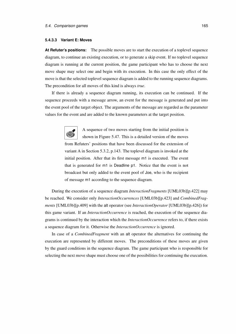
5.4. Comparison games 165
5.4.3.3 Variant E: Moves
At Refuter’s positions: The possible moves are to start the execution of a toplevel sequence
diagram, to continue an existing execution, or to generate a skip event. If no toplevel sequence
diagram is running at the current position, the game participant who has to choose the next
move shape may select one and begin with its execution. In this case the only effect of the
move is that the selected toplevel sequence diagram is added to the running sequence diagrams.
The precondition for all moves of this kind is always true.
If there is already a sequence diagram running, its execution can be continued. If the
sequence proceeds with a message arrow, an event for the message is generated and put into
the event pool of the target object. The arguments of the message are regarded as the parameter
values for the event and are added to the known parameters at the target position.
A sequence of two moves starting from the initial position is
shown in Figure 5.47. This is a detailed version of the moves
from Refuters’ positions that have been discussed for the extension of
variant A in Section 5.3.2, p.143. The toplevel diagram is invoked at the
initial position. After that its first message m1 is executed. The event
that is generated for m1 is Deadline p1. Notice that the event is not
broadcast but only added to the event pool of Joe, who is the recipient
of message m1 according to the sequence diagram.
During the execution of a sequence diagram InteractionFragments [UML03b][p.422] may
be reached. We consider only InteractionOccurrences [UML03b][p.423] and CombinedFrag-
ments [UML03b][p.409] with the alt operator (see InteractionOperator [UML03b][p.426]) for
this game variant. If an InteractionOccurrence is reached, the execution of the sequence dia-
grams is continued by the interaction which the InteractionOccurrence refers to, if there exists
a sequence diagram for it. Otherwise the InteractionOccurrence is ignored.
In case of a CombinedFragment with an alt operator the alternatives for continuing the
execution are represented by different moves. The preconditions of these moves are given
by the guard conditions in the sequence diagram. The game participant who is responsible for
selecting the next move shape must choose one of the possibilities for continuing the execution.

166 Chapter 5. Application to UML
default
Not enough staffPubX
Italy
invoke Deadline order
default
Not enough staffPubX
Italy
Deadline order:m1
default
Not enough staffPubX
Italy
Deadline order (T)
State configuration
Studying
ProjectPractical1
Analysis
Event poolName
Joe
History mapping
h2:
h1: Practical1
Analysis
Project
empty
empty
empty
p0: R
TypeName ValueContext
State configuration
Studying
ProjectPractical1
Analysis
Event poolName
Joe
History mapping
h2:
h1: Practical1
Analysis
Project
empty
empty
empty
TypeName ValueContext
p1: R
p2: V
State configuration
Studying
ProjectPractical1
Analysis
Name
Joe
empty
empty
Context
Event pool History mapping
h2:
h1: Practical1
Analysis
Project
ValueTypeName
e1: Deadline p1
OBJECTS
RUNNING SEQUENCE DIAGRAMS
Name Executed parts
PARAMETERS
OBJECTS
RUNNING SEQUENCE DIAGRAMS
Name
PARAMETERS
Executed parts
OBJECTS
RUNNING SEQUENCE DIAGRAMS
Name
PARAMETERS
Executed parts
m1Deadline order (T)
Figure 5.47: Example moves from Refuters’ positions in variant E
5.4. Comparison games 167
When the CombinedFragment in sequence diagram After
deadline is reached, the game participants can choose by
which fragment they want to continue the execution. The two moves
that may be selected at this point have preconditions enough savings
and else. They have already been shown for the extension of variant A
by sequence diagrams in Figure 5.33, p.147, in Section 5.3.2.
Generating a skip event offers the participant who is responsible for choosing the next move
shape at the succeeding position the possibility to fire a transition with an empty trigger. This
concept has been introduced for variant A in Section 5.2.3.3, p.90.
At Verifier’s positions: From Verifier’s positions the game participants move by firing a set
of transitions that are triggered by the events in the event pools, or have empty triggers in
case of a skip event. The main difference to the extension of variant A by sequence diagrams
described in Section 5.3.2, p.143, lies in the moves from Verifier’s position which correspond
to firing transitions with non-empty triggers. The game participant who has to respond to the
events in the event pools cannot simply fire any transition that is triggered. The activities which
are performed during each transition that is fired must fit the sequence diagram that is being
executed. That means, for all messages that are sent during the execution6 after the reception
of the last message according to the sequence diagram, a corresponding InvocationAction must
appear in the state machine which contains the fired transition. Furthermore the targets and
parameter values of each action must fit the target objects and arguments of the messages that
are sent during the execution.
Events representing the InvocationActions are generated and put into the event pools of
their target objects. Thereby the arrows in the sequence diagram determine whether an action
is performed synchronously or asynchronously. If the object expression or parameter values
in an action cannot be resolved, the transition may not be fired. The target position contains
the new state configurations, history mapping, event pools and parameters as described for
variant A (see Section 5.2.3.3, p.90). Furthermore the execution state of the running sequence
diagrams is changed. All messages that correspond to the events that have been generated
during the move are added to the executed parts of the running sequence diagrams.
6In UML this is called an ExecutionOccurrence[UML03b][p.417] and shown as grey rectangle on a lifeline inthe sequence diagram. For more information on sequence diagrams and their components see Section 2.1.2, p.10.
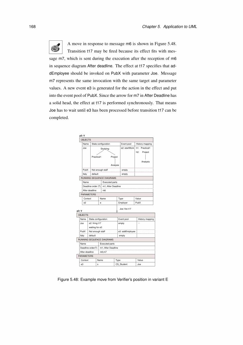
168 Chapter 5. Application to UML
A move in response to message m6 is shown in Figure 5.48.
Transition t17 may be fired because its effect fits with mes-
sage m7, which is sent during the execution after the reception of m6
in sequence diagram After deadline. The effect at t17 specifies that ad-
dEmployee should be invoked on PubX with parameter Joe. Message
m7 represents the same invocation with the same target and parameter
values. A new event e3 is generated for the action in the effect and put
into the event pool of PubX. Since the arrow for m7 in After Deadline has
a solid head, the effect at t17 is performed synchronously. That means
Joe has to wait until e3 has been processed before transition t17 can be
completed.
e2: firing t17
waiting for e3
default
Not enough staffPubX
Italy
e3 s CS_Student Joe
e3: addEmployee
...
default
Not enough staffPubX
Italy
e2 e Employer PubX
Joe: fire t17
State configurationName
Joe
Event pool
p3: V
empty
History mapping
empty
TypeNameContext Value
State configuration
Studying
ProjectPractical1
Analysis
Name
Joe
empty
empty
Event pool
p3: V
TypeName ValueContext
e2: startWork
History mapping
h2:
h1: Practical1
Analysis
Project
OBJECTS
RUNNING SEQUENCE DIAGRAMS
Name
Deadline order(T)
Executed parts
m1; After Deadline
After deadline
PARAMETERS
m6;m7
OBJECTS
RUNNING SEQUENCE DIAGRAMS
Name Executed parts
m1; After Deadline
After deadline
PARAMETERS
m6
Deadline order (T)
Figure 5.48: Example move from Verifier’s position in variant E
5.4. Comparison games 169
The possible responses to a skip move are the same as described for variant A. The game
participant who has to choose the next move shape can either fire a transition with empty trigger
or discard the skip event. For further details see Section 5.2.3.3, p.96. The precondition for
firing a set of transitions is as usual given by the conjunction of their guard conditions.
5.4.3.4 Variant E: Winning conditions
Refuter wins a play if one of the messages in the sequence diagrams cannot be realised in a state
machine. Since none of Refuter’s positions in the arena is a dead end, Verifier cannot win any
finite plays if there is not another winning condition defined for her. Refuter can theoretically
challenge Verifier repeatedly by the same sequence diagram forever. In order to forbid this and
enforce finiteness of a play, a winning condition specifying that Verifier wins when a move
limit is reached should be added.
Our example game is played with the default responsibility
settings and a move limit of 20. Verifier wins if the move
limit is reached. Refuter has a winning strategy for this game. He has
to initiate the execution of sequence diagram Deadline order, execute
it until the combined fragment in After deadline is reached for the first
time, and select the first fragment which involves sending m4. Since
Verifier cannot fire a transition with trigger TravelTo when Joe is in state
Studying, she is stuck and Refuter wins the play.
The situation changes if the responsibilities are distributed differently.
If Verifier is responsible for selecting a move shape every time before
the combined fragment is reached, and the Referee decides which part
of the combined fragment is executed, Verifier has an unsafe winning
strategy. She can win a play if the Referee always chooses the part of
the combined fragment that starts with m6, because she can respond by
firing t17 and t19 in this case if she evaluates the preconditions for these
moves to true.
170 Chapter 5. Application to UML
Alternatively, she can try to prepare herself for m4 by generating a skip
event from one of Refuter’s positions before the combined fragment is
reached. This allows Verifier to fire transition t20 if she evaluates the
precondition for this move to true. If Verifier performs this move, she
is able to react appropriately to message m4 by firing transition t21, be-
cause Joe is in state On Holiday at this point. However, if the game is
played with the default settings she still loses the play for a different rea-
son. According to the sequence diagram the effect ski at transition t21
corresponds to a synchronous invocation and is added to the event pool
of Joe. Since Joe is still processing the synchronous invocation of Trav-
elTo at this point, a deadlock occurs. This problem can be avoided by
changing the game settings such that recursive synchronous invocations
are discarded. If the game is played with the modified settings, Verifier
has another unsafe strategy which involves generating a skip event and
firing t20 before the combined fragment is processed.
5.4.3.5 Variant E: Responsibilities
In this game variant none of the moves is parameterised. The parameters for the generated
events are always taken from the UML diagrams. Either the arguments of messages in the
sequence diagrams or the parameter values for the actions in the state machines are used. Fur-
thermore the resolution of non-determinism never occurs for this variant because of the way
the game arena is created. Thus the only responsibilities that are relevant here are precondi-
tion evaluation and choice of move shape. Both of these responsibilities can be defined via
combinations of states or events for the game participants as explained for variant A in Sec-
tion 5.2.3, p.101.
5.4.3.6 Variant E: Game settings
Even though this game variant is strongly related to variant A, most of the game settings con-
sidered there are not relevant here. The sequence diagrams specify clearly which events may
be generated from Refuter’s positions and how the actions that appear in the state machines
are executed. It does not make much sense to allow call events to be discarded in the context
of this game variant, because the goal is to check realisability. The only settings from variant
5.4. Comparison games 171
A whose values are not fixed by the sequence diagram concern event dispatch, firing of tran-
sitions, and discarding of recursive synchronous invocations. For details on these settings see
Section 5.2.3, p.102. Apart from that there are no other variant specific settings for this game
variant.
5.4.3.7 Variant E: Incrementations
The Explorer can increment the game by the following variant specific moves:
• Add or delete a transition between two existing states in the state machines.
• Add or delete a state in the state machines. All transitions which point to or emerge from
a state that is deleted are also deleted.
• Change a trigger, guard or effect at a transition in the state machines.
• Add or delete a message between two lifelines in the sequence diagram.
• Change the name or arguments of a message.
• Change the guard condition at a fragment in a sequence diagram.
5.4.3.8 Variant E: Omitted UML features
The same features of state machines that have been omitted for variant A have also been omitted
here (see Section 5.2.3.8, p.109). Furthermore we have focused on InteractionOccurrences and
CombinedFragments with the alt InteractionOperator for the sequence diagrams in this game
variant. UML provides other kinds of InteractionFragments and operators to combine them
which have been omitted here.
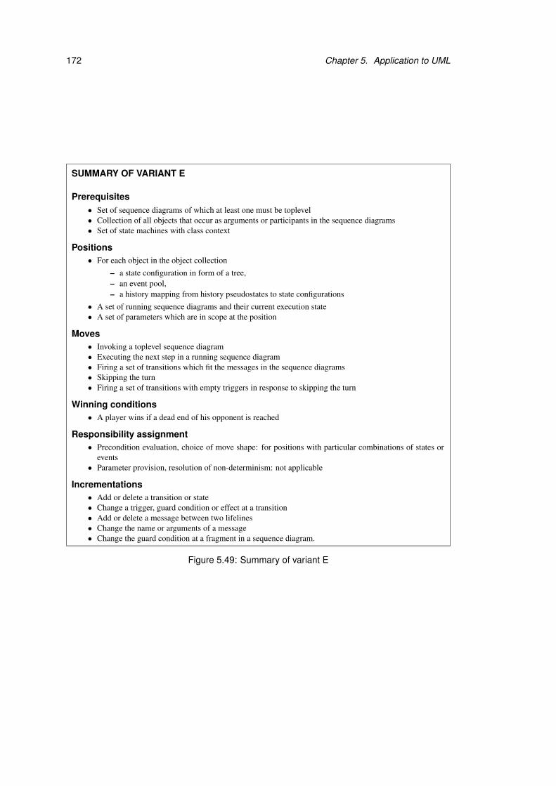
172 Chapter 5. Application to UML
SUMMARY OF VARIANT E
Prerequisites• Set of sequence diagrams of which at least one must be toplevel• Collection of all objects that occur as arguments or participants in the sequence diagrams• Set of state machines with class context
Positions• For each object in the object collection
– a state configuration in form of a tree,– an event pool,– a history mapping from history pseudostates to state configurations
• A set of running sequence diagrams and their current execution state• A set of parameters which are in scope at the position
Moves• Invoking a toplevel sequence diagram• Executing the next step in a running sequence diagram• Firing a set of transitions which fit the messages in the sequence diagrams• Skipping the turn• Firing a set of transitions with empty triggers in response to skipping the turn
Winning conditions• A player wins if a dead end of his opponent is reached
Responsibility assignment• Precondition evaluation, choice of move shape: for positions with particular combinations of states or
events• Parameter provision, resolution of non-determinism: not applicable
Incrementations• Add or delete a transition or state• Change a trigger, guard condition or effect at a transition• Add or delete a message between two lifelines• Change the name or arguments of a message• Change the guard condition at a fragment in a sequence diagram.
Figure 5.49: Summary of variant E

5.4. Comparison games 173
5.4.4 Variant F: State machine comparison
The game variant which is introduced in this section compares two state machines for the same
class with each other. The aim of Refuter is to find differences in the diagrams. Verifier tries
to prove that the state machines are equivalent. The notion of equivalence used here is that of
bisimulation equivalence [Mil89] if the game is played with the default responsibilities.
5.4.4.1 Variant F: Prerequisites
The basis for this game variant are two state machines with the same class context. Both
behavioural and protocol state machines are permitted. The execution of the state machines is
considered for one anonymous object of this class and an object collection is not required.
As example for this game variant we consider two ver-
sions of the state machine for CS Student, which are shown
in Figure 5.50 and Figure 5.51. The first version, which is called
CS Student 1, has already been used as example in previous game vari-
ants.
The second version CS Student 2 models the state On Holiday in more
detail than CS Student 1 by several substates. However, CS Student 1
contains more detail about state Studying than CS Student 2.
5.4.4.2 Variant F: Positions
The positions of this game variant consist of one state configuration for each state machine and
a history mapping. The two state machines are compared by checking whether the moves that
are possible in response to an event are the same for both state machines. Hence the positions
record the last move that has been made at one of Refuter’s positions. The last move can be the
firing of a transition or discarding of an event for one of the state machines. The positions do
not specify which parameters are in scope, because none of the moves in this game variant is
parameterised.
All positions where the last move is empty belong to Refuter. The remaining positions are
owned by Verifier. The initial position contains the default state configurations, a corresponding
history mapping, and an empty last move.

174 Chapter 5. Application to UML
H*
������ � �
Studying
Project
h1:
h2:
Project completed
t1:
t2:
e.removeEmployee(self)
[l in the mountains]/ski
[enough savings] [no savings]
[else]/matriculate;pay fees
[degree completed]
t3:
t14:
t13:
t11:t10:
t9:
t8:t7:
t6:
t15:
t16:
startWork(e:Employer)/e.addEmployee(self)
t17: t19:
t18:
t21:
t23:t20:
On Holiday
t12:
Documentation Implementation
DesignAnalysis
Practical1 Practicals completedPractical2
At Work
H
stopWork(e:Employer)/
CS_Student_1
Deadline project
TravelTo(l:Location)
[l on the sea]/swim
t22:TravelTo(l:Location)
Work/self.savings++
Deadline p1t4:
Deadline p2t5:
Figure 5.50: First version of state machine for CS Student in variant F
Figure 5.52 shows the initial position for our example. The
position contains the default configurations of both state ma-
chines, a mapping from history pseudostates h1 and h2 to subtrees of
the default configuration of CS Student 1, and an empty last move.
5.4.4.3 Variant F: Moves
In this game variant the ownership of the positions that are visited during a play alternates
strictly. After a move from Refuter’s positions a position belonging to Verifier is reached.
Similarly a position of Refuter is reached after each move that emerges from one of Verifier’s
positions.
At Refuter’s positions At these positions the game participants have to generate an event,
select one state machine, and react to the generated event in the chosen state machine. All
of these steps happen in one single move. The generated event can be a trigger in any of the
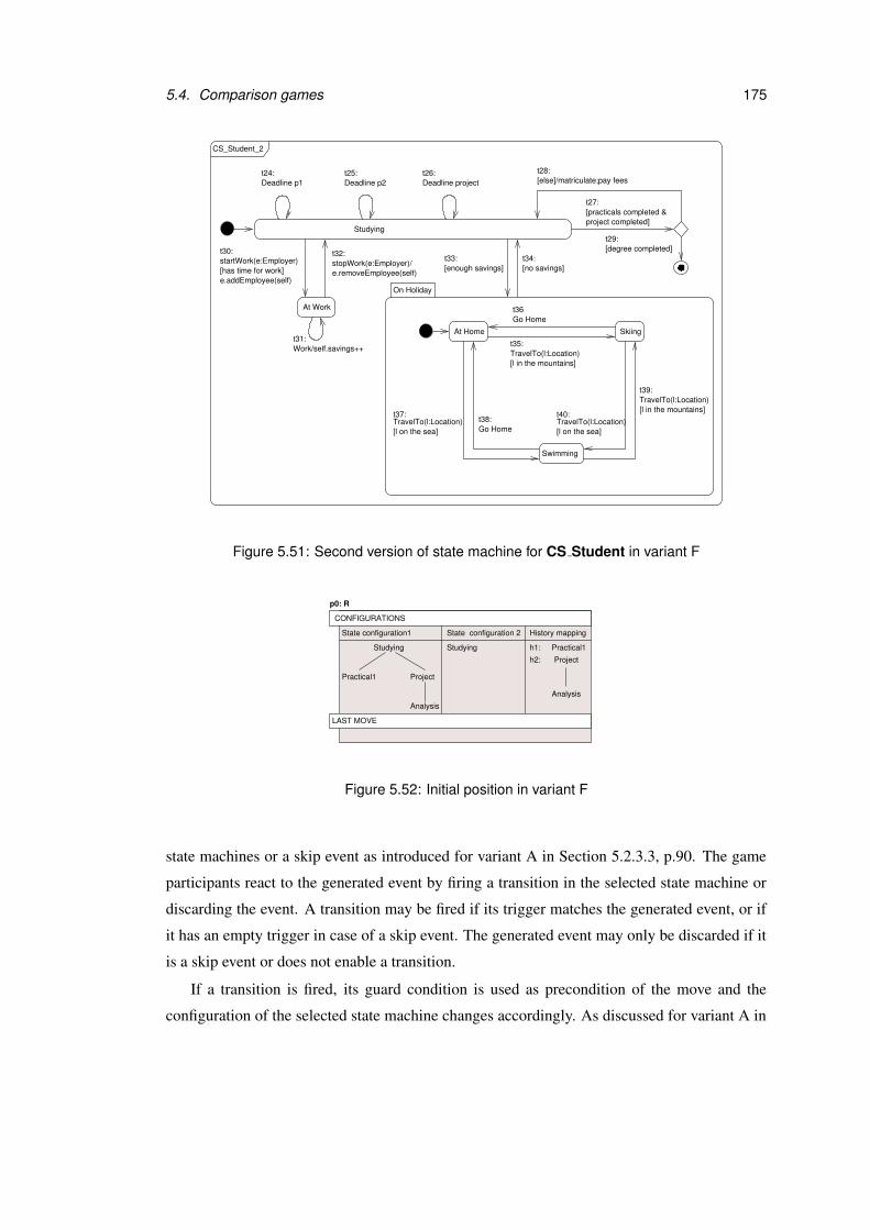
5.4. Comparison games 175
[enough savings]t33:
[no savings]t34:
t27:[practicals completed &project completed]
!�!!�!"�""�"
Swimming
SkiingAt Home
Studying
e.removeEmployee(self)
At Work
stopWork(e:Employer)/
t30:startWork(e:Employer)[has time for work]e.addEmployee(self)
t31:
t32:[degree completed]t29:
CS_Student_2
On Holiday
t26:[else]/matriculate;pay feest28:
Work/self.savings++
Deadline projectDeadline p1t24:
Deadline p2t25:
t38:t37:
[l on the sea]
[l in the mountains]
t35:
t36
[l on the sea]
t40:[l in the mountains]
t39:
TravelTo(l:Location)
Go Home
TravelTo(l:Location)
Go HomeTravelTo(l:Location)
TravelTo(l:Location)
Figure 5.51: Second version of state machine for CS Student in variant F
h1: Practical1
h2: Project
Analysis
p0: R
Studying
ProjectPractical1
Analysis
State configuration1 State configuration 2 History mapping
Studying
CONFIGURATIONS
LAST MOVE
Figure 5.52: Initial position in variant F
state machines or a skip event as introduced for variant A in Section 5.2.3.3, p.90. The game
participants react to the generated event by firing a transition in the selected state machine or
discarding the event. A transition may be fired if its trigger matches the generated event, or if
it has an empty trigger in case of a skip event. The generated event may only be discarded if it
is a skip event or does not enable a transition.
If a transition is fired, its guard condition is used as precondition of the move and the
configuration of the selected state machine changes accordingly. As discussed for variant A in

176 Chapter 5. Application to UML
Section 5.2.3.3, p.92, the precondition for discarding an event is either true or the conjunction
of the negated guard conditions of the transitions that are triggered by the event. If the generated
event is discarded, the state machine configurations at the source and target position are the
same.
Consider the example moves shown in Figure 5.53. If event
startWork is generated and the first state machine version is
chosen, transition t17 has to be fired. The target position of this move is
p1 and contains At Work as new configuration for the first state machine
version. The diagram also shows a move which involves a reaction to a
skip event for the second state machine version. Transition t33 is fired
and the configuration of the second state machine version is changed to
On Holiday and substate At Home at position p2.
skip=>
...
[enough savings]
On Holiday
At Home
...
CS_Student_1: fire t17
startWork=>
CS_Student_1: fire t17
CS_Student_2: fire t33
CS_Student_2: fire t33
h1: Practical1
h2: Project
Analysis
h1: Practical1
h2: Project
Analysis
Studying
ProjectPractical1
Analysis
p2: V
State configuration1
p1: V
At Work
State configuration 2 History mapping
Studying
State configuration1 State configuration 2 History mapping
Studying
ProjectPractical1
Analysis
p0: R
State configuration1 State configuration 2 History mapping
Studying
CONFIGURATIONS
LAST MOVE
CONFIGURATIONS
LAST MOVE
CONFIGURATIONS
LAST MOVE
Figure 5.53: Example moves from Refuter’s position in variant F

5.4. Comparison games 177
At Verifier’s positions The game participants have to show that the last move can be made
for both state machines. If the last move refers to the first state machine version, the second
state machine version must be considered in this move, and vice versa.
If the last move corresponds to firing a transition with non-empty trigger, a transition with
the same trigger and effect must be fired in the other state machine. Furthermore the transition
must involve the same entry- exit- and do-activities as specified in the other state machine. The
precondition of this move is given by the guard condition of the transition. The target position
contains the new state configuration for the state machine in which the transition is fired, and
its last move is empty.
In case the last generated event was not a skip event and was discarded during the last
move, the game participants must discard the event for the other state machine. As for the
moves from Refuter’s position this is only permitted if the event does not enable a transition in
the state machine. The state configurations do not change and the last move is removed.
If a transition with empty trigger was fired or a skip event was discarded during the last
move, then there is no obligation to imitate this reaction to a skip event in the following move
from Verifier’s position. The skip event offers the game participants the chance to fire a transi-
tion with empty trigger or discard the event. Thereby it does not matter whether the effect of a
transition matches the one of the previously fired transition or whether the skip event has been
discarded in the last move.
Figure 5.54 shows the possible reaction to the move from Re-
futer’s position p0 to p1 that was discussed as example in the
previous section (see Figure 5.53, p.176). The last move corresponded
to firing transition t17 in state machine CS Student 1. From position p1
the game participant is allowed to fire t30 in state machine CS Student 2
because it matches t17. It is triggered by the same event and has the
same effect. The precondition for firing t30 is given by its guard condi-
tion has time for work. At the target position p2 of this move the state
configuration for CS Student 2 is At Work.
5.4.4.4 Variant F: Winning conditions
A play is won by Refuter if the comparison between the two state machines fails. Since events
can always be generated from Refuter’s positions, none of his positions is a dead end. That
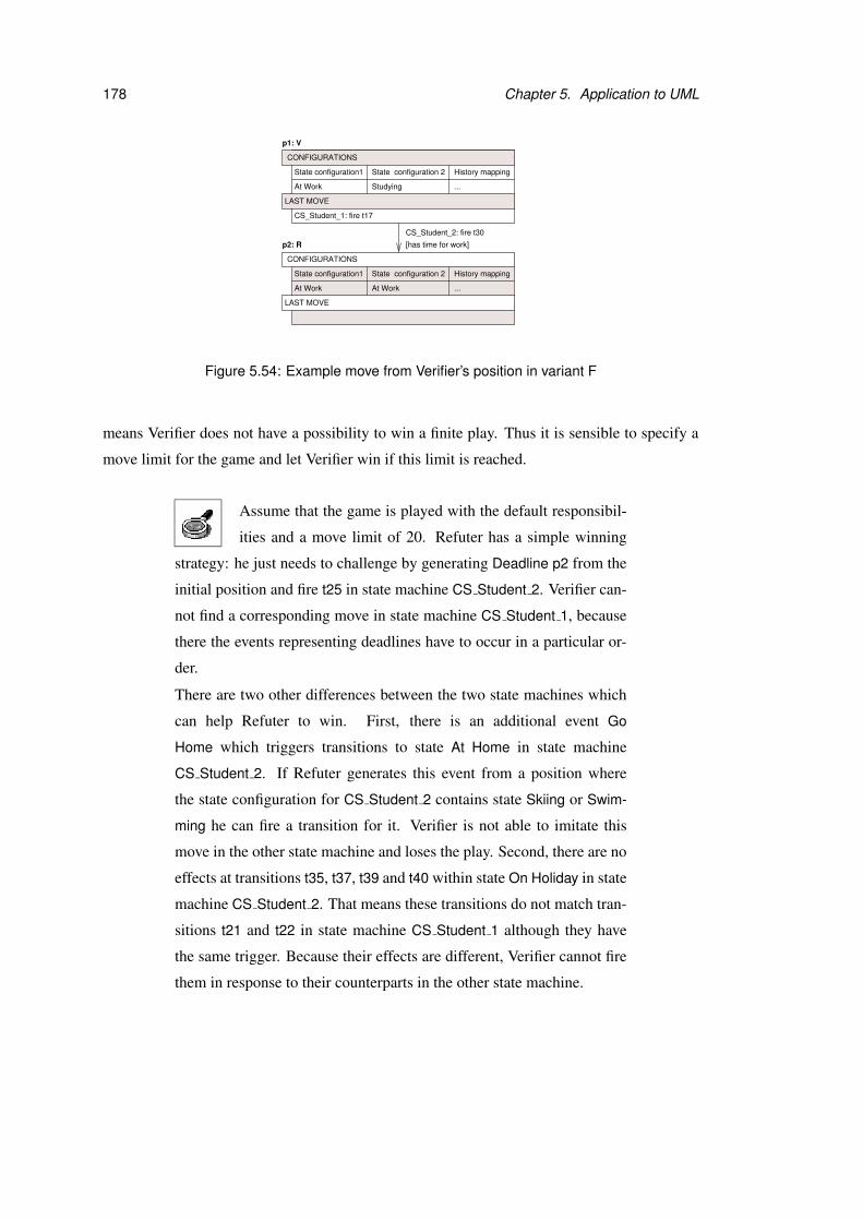
178 Chapter 5. Application to UML
...
...
[has time for work]
CS_Student_1: fire t17
CS_Student_2: fire t30
State configuration1
At Work
State configuration 2 History mapping
At Work
State configuration1
p1: V
At Work
State configuration 2 History mapping
Studying
p2: R
CONFIGURATIONS
LAST MOVE
CONFIGURATIONS
LAST MOVE
Figure 5.54: Example move from Verifier’s position in variant F
means Verifier does not have a possibility to win a finite play. Thus it is sensible to specify a
move limit for the game and let Verifier win if this limit is reached.
Assume that the game is played with the default responsibil-
ities and a move limit of 20. Refuter has a simple winning
strategy: he just needs to challenge by generating Deadline p2 from the
initial position and fire t25 in state machine CS Student 2. Verifier can-
not find a corresponding move in state machine CS Student 1, because
there the events representing deadlines have to occur in a particular or-
der.
There are two other differences between the two state machines which
can help Refuter to win. First, there is an additional event Go
Home which triggers transitions to state At Home in state machine
CS Student 2. If Refuter generates this event from a position where
the state configuration for CS Student 2 contains state Skiing or Swim-
ming he can fire a transition for it. Verifier is not able to imitate this
move in the other state machine and loses the play. Second, there are no
effects at transitions t35, t37, t39 and t40 within state On Holiday in state
machine CS Student 2. That means these transitions do not match tran-
sitions t21 and t22 in state machine CS Student 1 although they have
the same trigger. Because their effects are different, Verifier cannot fire
them in response to their counterparts in the other state machine.

5.4. Comparison games 179
5.4.4.5 Variant F: Responsibilities
Since none of the moves in this game variant has parameters and the arena is deterministic,
only the responsibilities for the evaluation of preconditions and choice of move shapes have to
be considered. These responsibilities can be assigned by defining state combinations for the
two state machine versions. Moreover the trigger of the last move can be used to identify a set
of positions at which a specific game participant is responsible for a task.
Example responsibilities for this game variant are shown in
table 5.5. Refuter is responsible for evaluating precondi-
tions at all positions where the last move was a reaction to event start-
Work(e:Employer). At all positions where the state configurations for
both state machines contain state On Holiday, Verifier chooses the next
move shape.
5.4.4.6 Variant F: Game settings
There exist no variant specific settings for this game variant. The settings for other game
variants which are also based on state machines, like variants A and D, are not relevant here,
because the focus of this variant is on the comparison of the two state machine diagrams.
5.4.4.7 Variant F: Incrementations
The following incrementations are permitted for this game variant:
• Add or delete a transition between two existing states in any of the two state machines.
• Add or delete a state in any of the two state machines. All transitions which point to or
emerge from the deleted state are also deleted.
• Change the trigger, guard condition or effect at a transition in any of the two state ma-
chines.
5.4.4.8 Variant F: Omitted UML features
The same features of state machines that have been omitted for variant A have also been omitted
here. For more details see Section 5.2.3.8, p.109.
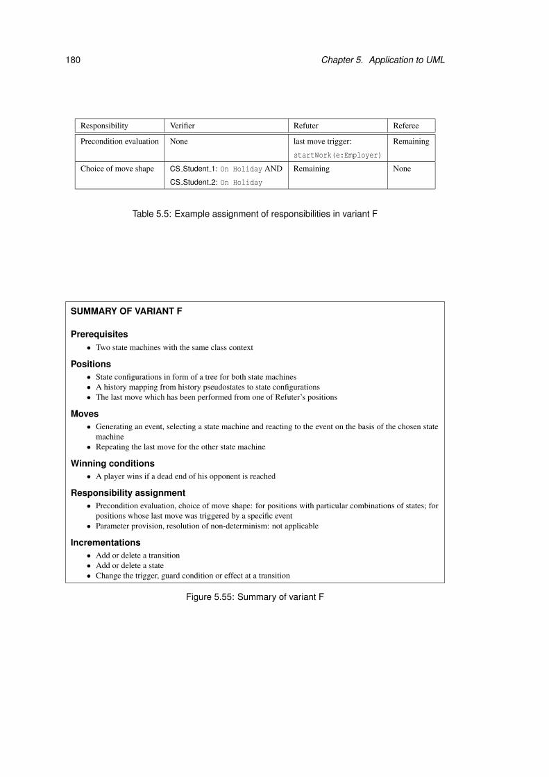
180 Chapter 5. Application to UML
Responsibility Verifier Refuter Referee
Precondition evaluation None last move trigger: Remaining
startWork(e:Employer)
Choice of move shape CS Student 1: On Holiday AND Remaining None
CS Student 2: On Holiday
Table 5.5: Example assignment of responsibilities in variant F
SUMMARY OF VARIANT F
Prerequisites• Two state machines with the same class context
Positions• State configurations in form of a tree for both state machines• A history mapping from history pseudostates to state configurations• The last move which has been performed from one of Refuter’s positions
Moves• Generating an event, selecting a state machine and reacting to the event on the basis of the chosen state
machine• Repeating the last move for the other state machine
Winning conditions• A player wins if a dead end of his opponent is reached
Responsibility assignment• Precondition evaluation, choice of move shape: for positions with particular combinations of states; for
positions whose last move was triggered by a specific event• Parameter provision, resolution of non-determinism: not applicable
Incrementations• Add or delete a transition• Add or delete a state• Change the trigger, guard condition or effect at a transition
Figure 5.55: Summary of variant F
5.5. Conclusion 181
5.5 Conclusion
Several example variants of exploration games based on UML design models have been in-
troduced in this chapter. The variety of examples has demonstrated that the exploration game
framework is flexible enough to be used for a wide range of design explorations. Among the
game definitions that have been considered, some are used to check certain properties of the de-
sign, while others serve the examination of the relationship between different UML diagrams.
Each of the variants presented here illustrates in detail how a game may be defined. Addi-
tionally, these example definitions can be used as guidelines for the creation of new variants.
The plays discussed here have shown that exploration games are a useful means for finding
errors in the design model and its specification. Our variations of the responsibilities and dif-
ferent decisions by the game participants have often changed the progress and final outcome of
a play completely. The incrementations by the Explorer have been induced by the discoveries
during a play and have improved the precision of the UML diagrams or winning conditions.
In the UML examples given in this chapter we have modelled different aspects of a system
by complementary views as intended by UML. Thereby we have followed the recommenda-
tions in the UML specification and commonly accepted modelling practices. Thus our detailed
variant descriptions do not only show how exploration games can be defined on the basis of
UML, but also how several UML diagram types may be combined such that they constitute a
reasonable foundation for a game.

Chapter 6
Prototype implementation
In this chapter we describe our prototype implementation GUIDE (Games with UML for
Interactive Design Exploration) which is based on the exploration game framework. The
GUIDE tool, installation instructions and further documentation can be found on the CD en-
closed at the end of this thesis and online [Gui]. The functionality of GUIDE is illustrated on
the example game and plays which have been presented in Chapter 3. In order to allow more
room for experimentation with GUIDE, the game settings have been extended by tool specific
settings, which are introduced here. Not all parts of the exploration game framework and ex-
ample game variant have been implemented in GUIDE, and we summarise which aspects have
been omitted. After that we give an overview on the technologies that have been used for the
implementation and on GUIDE’s architecture. This chapter is concluded with an explanation
of how the tool can be extended by additional game variants and alternative algorithms.
6.1 Functionality of the GUIDE tool
6.1.1 Creation of the UML model
Before a game can be set up with GUIDE, a UML model has to be created. GUIDE does
not contain a visual editor and requires a file in XMI format [XMI02] that is compliant to
the UML1.4 metamodel [UML01] from an external UML tool as input. The test models for
GUIDE have been created with the community edition of the Poseidon tool [Pos]. GUIDE
allows the user to save the UML model back to XMI at any point, which is important if the
model is changed during a play. Any new version of the model which has been produced
by GUIDE can be opened by UML tools that support exchange of models in XMI format,
183

184 Chapter 6. Prototype implementation
Student
EndOfYear[else]
t3:EndOfYear
t4:matriculate()
matriculate()
t2:StartOfYear
t5:
t6:
t1:addModule(m:Module)
Enrolling Studying
Taking Exams
ProposedScheduled
EndOfYear StartOfYear
Module
t7:
t9:t10:
Open
t8:
s.addModule(self)enrol(s::Student)/
Being Taught
[practicals passed]
On Holiday
Figure 6.1: State machines for Module and Student
such as Poseidon. The XMI file does not contain layout data or information about any other
graphic aspects of the UML diagrams. These details have to be supplemented by the user in
the external UML tool. In Poseidon the user can add the model elements from the XMI file to
UML diagrams and then change their appearance with Poseidon’s diagram editor.
We have chosen an old version of the UML metamodel, because most UML tools still use
this version at the time of writing. GUIDE expects the UML model to be syntactically correct
and well-formed. The state machines of the UML model from Chapter 3, which are used as
example here, are shown again in Figure 6.1.
6.1.2 Game setup
Figure 6.2 shows the main window of GUIDE after a project based on our example UML model
has been opened. There is a menubar on top of the window, a model tree which displays the
UML model on the left hand side, a game panel with six different views on the right, and a
message window at the bottom. The views in the game panel are controlled by the game tabs
on top of the panel. Each view shows a particular part of the game definition. The definition of
a new game involves the following steps using the menubar:
1. Open the UML model by File→Open Model, which displays a file dialogue.
2. Set the arena type by Edit→Arena type, which opens a dialogue where the user can
select one of the types that are currently available in GUIDE. The arena type specifies
the game variant and determines which parts of the UML model are used within the
game. The GUIDE prototype contains an implementation of variant A, which is based
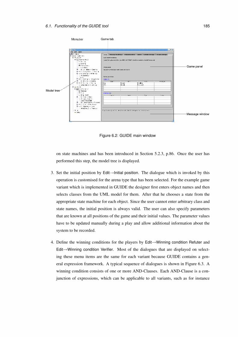
6.1. Functionality of the GUIDE tool 185
Figure 6.2: GUIDE main window
on state machines and has been introduced in Section 5.2.3, p.86. Once the user has
performed this step, the model tree is displayed.
3. Set the initial position by Edit→Initial position. The dialogue which is invoked by this
operation is customised for the arena type that has been selected. For the example game
variant which is implemented in GUIDE the designer first enters object names and then
selects classes from the UML model for them. After that he chooses a state from the
appropriate state machine for each object. Since the user cannot enter arbitrary class and
state names, the initial position is always valid. The user can also specify parameters
that are known at all positions of the game and their initial values. The parameter values
have to be updated manually during a play and allow additional information about the
system to be recorded.
4. Define the winning conditions for the players by Edit→Winning condition Refuter and
Edit→Winning condition Verifier. Most of the dialogues that are displayed on select-
ing these menu items are the same for each variant because GUIDE contains a gen-
eral expression framework. A typical sequence of dialogues is shown in Figure 6.3. A
winning condition consists of one or more AND-Clauses. Each AND-Clause is a con-
junction of expressions, which can be applicable to all variants, such as for instance
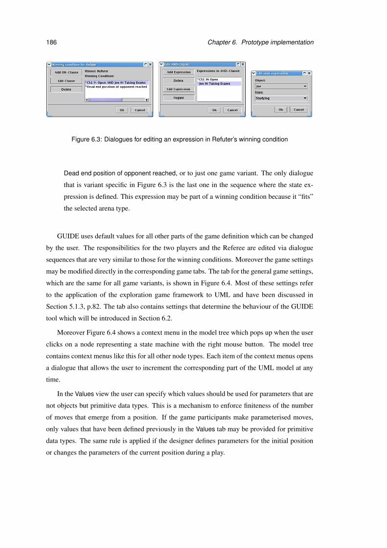
186 Chapter 6. Prototype implementation
Figure 6.3: Dialogues for editing an expression in Refuter’s winning condition
Dead end position of opponent reached, or to just one game variant. The only dialogue
that is variant specific in Figure 6.3 is the last one in the sequence where the state ex-
pression is defined. This expression may be part of a winning condition because it “fits”
the selected arena type.
GUIDE uses default values for all other parts of the game definition which can be changed
by the user. The responsibilities for the two players and the Referee are edited via dialogue
sequences that are very similar to those for the winning conditions. Moreover the game settings
may be modified directly in the corresponding game tabs. The tab for the general game settings,
which are the same for all game variants, is shown in Figure 6.4. Most of these settings refer
to the application of the exploration game framework to UML and have been discussed in
Section 5.1.3, p.82. The tab also contains settings that determine the behaviour of the GUIDE
tool which will be introduced in Section 6.2.
Moreover Figure 6.4 shows a context menu in the model tree which pops up when the user
clicks on a node representing a state machine with the right mouse button. The model tree
contains context menus like this for all other node types. Each item of the context menus opens
a dialogue that allows the user to increment the corresponding part of the UML model at any
time.
In the Values view the user can specify which values should be used for parameters that are
not objects but primitive data types. This is a mechanism to enforce finiteness of the number
of moves that emerge from a position. If the game participants make parameterised moves,
only values that have been defined previously in the Values tab may be provided for primitive
data types. The same rule is applied if the designer defines parameters for the initial position
or changes the parameters of the current position during a play.
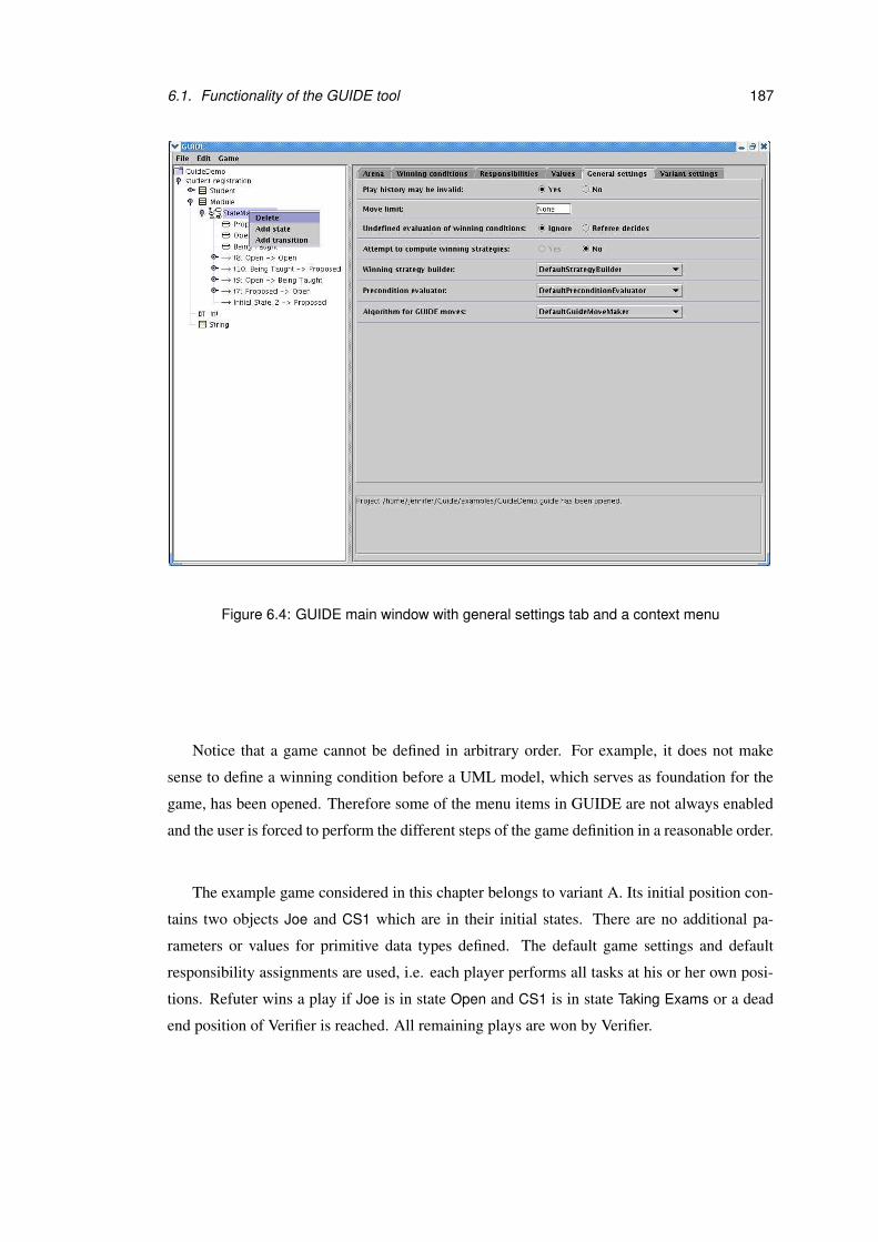
6.1. Functionality of the GUIDE tool 187
Figure 6.4: GUIDE main window with general settings tab and a context menu
Notice that a game cannot be defined in arbitrary order. For example, it does not make
sense to define a winning condition before a UML model, which serves as foundation for the
game, has been opened. Therefore some of the menu items in GUIDE are not always enabled
and the user is forced to perform the different steps of the game definition in a reasonable order.
The example game considered in this chapter belongs to variant A. Its initial position con-
tains two objects Joe and CS1 which are in their initial states. There are no additional pa-
rameters or values for primitive data types defined. The default game settings and default
responsibility assignments are used, i.e. each player performs all tasks at his or her own posi-
tions. Refuter wins a play if Joe is in state Open and CS1 is in state Taking Exams or a dead
end position of Verifier is reached. All remaining plays are won by Verifier.

188 Chapter 6. Prototype implementation
6.1.3 Playing a game
Once the user is satisfied with the game set up, he can start to play by Game→Play. A dialogue
as shown in Figure 6.5 appears and asks the user for the distribution of tasks during the play.
After that the play window, which contains the current position and play history, is displayed
and the players start to move. Figure 6.6 shows a play of our example game without exploration
in the play window. When the last position of this play is reached, GUIDE discovers that
Refuter’s winning condition holds. The play is finished and GUIDE announces that Refuter is
the winner.
Figure 6.5: Preparation of a play
Each move consists of the four stages precondition evaluation, choice of move shape, pa-
rameter provision and resolution of non-determinism that were explained in Chapter 3 and
more formally in Chapter 4. The algorithm for GUIDE moves, which is selected in the general
settings tab, computes how GUIDE performs these move steps in the role of the players or
the Referee. If the settings specify that GUIDE should attempt to compute winning strategies
for the players, these strategies may be used in the algorithm for the computation of GUIDE’s
move steps. Furthermore the user can determine whether the move steps that are made by
GUIDE should be displayed. If the user has to perform a part of the move, he is asked for input
by different dialogue windows. Figure 6.7 shows a sequence of move steps in the example
game where the user plays both Refuter and Verifier.
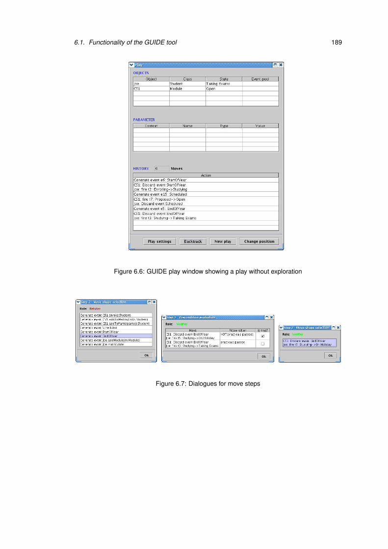
6.1. Functionality of the GUIDE tool 189
Figure 6.6: GUIDE play window showing a play without exploration
Figure 6.7: Dialogues for move steps

190 Chapter 6. Prototype implementation
At any time during a play the user can increment the game definition as specified by the
formal exploration game framework. He is not forced to answer the dialogues that are displayed
immediately and can use the context menus in the model tree, the items of the Edit menu and
the features in the game settings tabs to increment the game. Moreover the Change position
button in the play window permits modifications of the current position during a play. Each
change of position results in an incrementation of the game arena because the new position
becomes the target of the last move. Whenever the modeller performs an incrementation, a
short description is displayed in the play history. Figure 6.8 shows the history of a play during
which a new state and transition have been added to the UML model and the winning condition
for Verifier has been changed.
Figure 6.8: GUIDE play window showing a play with exploration
6.2. Tool specific game settings 191
The Backtrack button in the play window allows the modeller go back to an earlier position
of the play which can be selected in the history. Backtracking includes the incrementations
of the game, i.e. the game definition is also changed back to an earlier version. For example,
clicking the Backtrack button in the play window shown in Figure 6.8 would restore the old
version of Refuter’s winning condition and remove transition t12 from the UML model. After
backtracking the play would continue at the second item of the play history, which is selected.
6.2 Tool specific game settings
The general game settings for exploration games have been extended by tool specific settings
for the prototype implementation. These additional settings can be used to define if and how
winning strategies are computed, how formally defined preconditions are evaluated and how
the tool makes moves on behalf of the game participants.
Attempt to compute winning strategies (P) Winning strategies may be used by the algo-
rithm which specifies how the prototype tool moves on behalf of the players. This algorithm
is selected via the setting Algorithm for GUIDE moves which is discussed later in this section.
At an early design stage the user may not consider it worthwhile to wait for the computation
of winning strategies. This setting defines whether the GUIDE tool should attempt to find win-
ning strategies for the players. If so, a new winning strategy has to be computed whenever the
Explorer increments the game during a play. GUIDE also has to recompute a winning strategy
if the strategy is unsafe and turns out to be inapplicable during a play.
1. Default: The tool does not attempt to compute winning strategies for the players.
2. The tool attempts to compute winning strategies at the beginning and whenever the game
definition has changed or a winning strategy has become invalid. The computation of a
winning strategy can be interrupted and cancelled at any time by the user.
Winning strategy builder (P) This setting identifies the component that provides the algo-
rithm for computing winning strategies. The default winning strategy builder requires a move
limit to be specified because the computation involves building the arena up from the initial
position until the move limit is reached. Thus the higher the move limit is set, the longer the
computation of the winning strategy may take.
192 Chapter 6. Prototype implementation
1. Default: The default winning strategy builder, which builds winning strategies up depth
first. A brief description of the algorithm used for this component can be found in Sec-
tion 4.6, p.70.
2. A user-defined component which has been added to GUIDE and implements the required
interface (see Section 6.6).
Precondition evaluator (P) Whenever a new position is reached during a play, the precon-
ditions of the moves emerging from it are evaluated automatically. The game participants are
responsible for deciding about the legality of a move only if the evaluation of its precondi-
tion by the GUIDE tool is undefined. This setting specifies which component is used for the
precondition evaluation of moves.
1. Default: The default precondition evaluator, which always leaves the evaluation of the
preconditions to the game participants. The evaluation of each precondition is regarded
as undefined, no matter if the precondition is formally or informally specified.
2. A user-defined component which has been added to GUIDE and implements the required
interface (see Section 6.6).
Algorithm for GUIDE moves (P) The GUIDE tool may act on behalf of all game participants
except the Explorer, who must always be controlled by the user. This setting defines which
component in GUIDE performs the move steps for the game participants that are not played by
the user.
1. Default: The default component for making GUIDE moves, which moves randomly for
the Referee and uses safe or unsafe winning strategies to make moves for the players
where possible. If the computation of winning strategies is disabled, or no winning
strategy could be found for a player, GUIDE performs random move steps for this player.
2. A user-defined component which has been added to GUIDE and implements the required
interface (see Section 6.6).

6.3. Restrictions of the implementation 193
6.3 Restrictions of the implementation
GUIDE is a prototypical proof-of-concept tool, and does not cover the general aspects of the
exploration game framework or the features of the implemented example variant completely.
With respect to UML our prototype implementation of variant A is restricted to simple state
diagrams without hierarchical states or concurrent regions. Pseudostates are not supported,
except for final states, transitions with empty triggers are ignored, and the class names are as-
sumed to be unique. Furthermore recursive synchronous invocations via more than two objects
have not been considered in the implementation.
Winning conditions can be defined by the general conditions for all game variants as de-
scribed in Section 5.1.1, p.78, and by state combinations. The general conditions may not be
combined with other conditions by the AND operator. Moreover the definition of winning
conditions via event occurrences or temporal conditions, which have been introduced for vari-
ant A in Section 5.2.3.4, p.98, is not supported by the tool. GUIDE does not check before a
play whether the winning conditions for the two players cover all plays or overlap. If such a
situation arises during a play, the game setting for undefined evaluation of winning conditions
specifies what should happen at this point.
Similar restrictions apply to the definition of responsibilities. The general possibilities for
defining responsibility sets as introduced in Section 5.1.2, p.80, have been implemented in
GUIDE. Moreover the variant specific alternatives of assigning responsibilities via state com-
binations and event names, which have been discussed in Section 5.2.3.5, p.101, are available.
Only the identification of position sets by event occurrences has been omitted for the imple-
mentation. As for the winning conditions GUIDE does not check before a play whether the
responsibilities cover all positions and moves, or if they overlap. If the responsibility for a
task that has to be performed during a play is not clearly defined, this task is performed by the
Referee.
In GUIDE the initial position of a game always has to be defined manually by the designer.
For the settings concerning undefined position parts and discarding of synchronous recursive
invocations only the default options have been implemented. That means any part of a position
may be undefined and synchronous recursive invocations always lead to deadlocks. Apart from
that all options for the general settings as presented in Section 5.1.3, p.82, are supported.
The variant specific game settings for variant A, which were considered in Sec-
tion 5.2.3.6, p.102, have been reduced to the setting concerning the discarding of call events
and the execution of activities. For the latter only the invocation kind is regarded and can be set
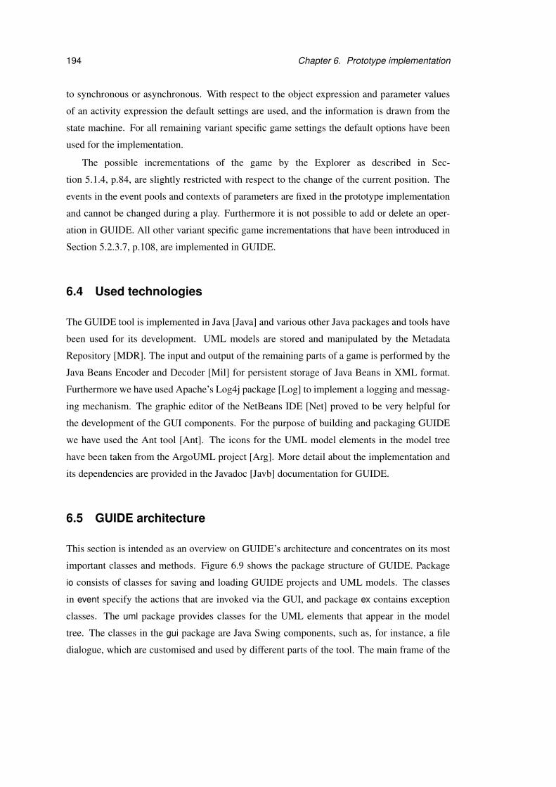
194 Chapter 6. Prototype implementation
to synchronous or asynchronous. With respect to the object expression and parameter values
of an activity expression the default settings are used, and the information is drawn from the
state machine. For all remaining variant specific game settings the default options have been
used for the implementation.
The possible incrementations of the game by the Explorer as described in Sec-
tion 5.1.4, p.84, are slightly restricted with respect to the change of the current position. The
events in the event pools and contexts of parameters are fixed in the prototype implementation
and cannot be changed during a play. Furthermore it is not possible to add or delete an oper-
ation in GUIDE. All other variant specific game incrementations that have been introduced in
Section 5.2.3.7, p.108, are implemented in GUIDE.
6.4 Used technologies
The GUIDE tool is implemented in Java [Java] and various other Java packages and tools have
been used for its development. UML models are stored and manipulated by the Metadata
Repository [MDR]. The input and output of the remaining parts of a game is performed by the
Java Beans Encoder and Decoder [Mil] for persistent storage of Java Beans in XML format.
Furthermore we have used Apache’s Log4j package [Log] to implement a logging and messag-
ing mechanism. The graphic editor of the NetBeans IDE [Net] proved to be very helpful for
the development of the GUI components. For the purpose of building and packaging GUIDE
we have used the Ant tool [Ant]. The icons for the UML model elements in the model tree
have been taken from the ArgoUML project [Arg]. More detail about the implementation and
its dependencies are provided in the Javadoc [Javb] documentation for GUIDE.
6.5 GUIDE architecture
This section is intended as an overview on GUIDE’s architecture and concentrates on its most
important classes and methods. Figure 6.9 shows the package structure of GUIDE. Package
io consists of classes for saving and loading GUIDE projects and UML models. The classes
in event specify the actions that are invoked via the GUI, and package ex contains exception
classes. The uml package provides classes for the UML elements that appear in the model
tree. The classes in the gui package are Java Swing components, such as, for instance, a file
dialogue, which are customised and used by different parts of the tool. The main frame of the

6.5. GUIDE architecture 195
expression algorithm
expression algorithm
GUIDE
exuml
io event framework
game
game
GuideFactory GuideProject UMLUtils
gui
variants
Figure 6.9: The package structure of GUIDE
GUI is also located in the gui package. All other GUI components are stored further down in
the package hierarchy in subpackages of the game, expression and algorithm packages.
The most interesting parts of the system are the framework and variants package. As shown
in Figure 6.9 they both have the same structure. The framework package provides general
classes and interfaces which can be refined and realised in the variants package. The class
GuideFactory consists of methods for finding classes in the variants package which implement
particular interfaces or are subclasses of framework classes. Java’s reflection mechanism is used
for this purpose. The relation between the framework and variants package is further discussed
in Section 6.6.
Figure 6.10 shows the part of GUIDE that contains the game structure. As in the formal
exploration game framework, a Game consists of an arena, an initial position, winning condi-
tions, responsibility assignments and game settings. The UML model of a game is given by
a UmlPackage which is a class in MDR. The abstract classes Arena, Settings and MoveCom-
ponent are specialised by concrete classes in the variants package. The concrete subclass of
Arena for game variant A is based on UML state machines. The variant specific settings are
represented by a subclass of Settings and refer to the UML state machine semantics. The con-
crete subclasses of MoveComponent for variant A stand for generating events, firing transitions
and discarding events.
The part of GUIDE’s game framework that is essential for playing a game is shown in
Figure 6.11. The GameEngine is invoked by the GUI and controls the play. It is linked to a
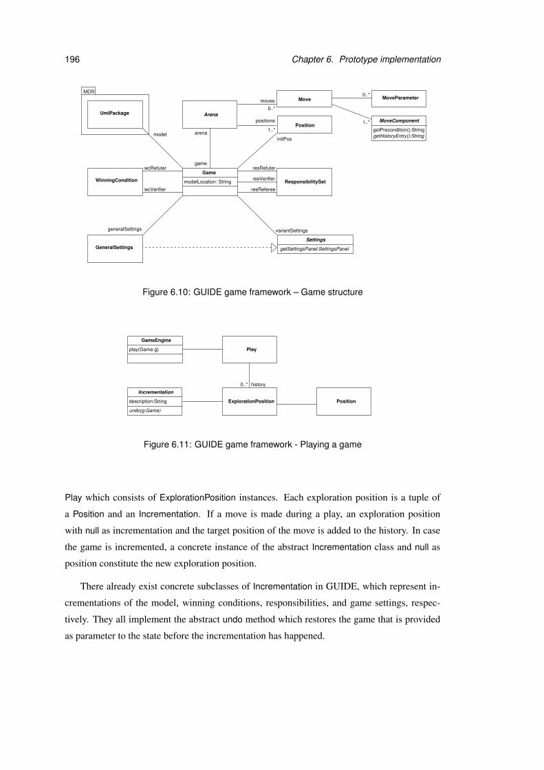
196 Chapter 6. Prototype implementation
Position
Move
Game
modelLocation: String
initPosmodel
resRefuter
resReferee
resVerifier
MDR
positions
1..*
0..*
moves
wcRefuter
WinningCondition
UmlPackage
ResponsibilitySet
variantSettingsgeneralSettings
0..*
1..*
GeneralSettings
wcVerifier
arena
Arena
game
getPrecondition():String
MoveParameter
MoveComponent
getHistoryEntry():String
getSettingsPanel:SettingsPanel
Settings
Figure 6.10: GUIDE game framework – Game structure
play(Game g)
GameEngine
Play
ExplorationPosition Position
history
Incrementation
undo(g:Game)
description:String
0..*
Figure 6.11: GUIDE game framework - Playing a game
Play which consists of ExplorationPosition instances. Each exploration position is a tuple of
a Position and an Incrementation. If a move is made during a play, an exploration position
with null as incrementation and the target position of the move is added to the history. In case
the game is incremented, a concrete instance of the abstract Incrementation class and null as
position constitute the new exploration position.
There already exist concrete subclasses of Incrementation in GUIDE, which represent in-
crementations of the model, winning conditions, responsibilities, and game settings, respec-
tively. They all implement the abstract undo method which restores the game that is provided
as parameter to the state before the incrementation has happened.

6.5. GUIDE architecture 197
evaluate(m:Move):Booleanevaluate(p:Position):Booleanevaluate(p:Play, gs:GeneralSettings, vs:Settings ):Boolean
AndClause
<<Interface>>ResponsibilityExpPosIF
evaluate(p:Position):Boolean
<<Interface>>ResponsibilityExpMoveIF
evaluate(m:Move):Boolean
<<Interface>>
Expression
<<Interface>>
ndtRes
paraProvRes0..*
0..*
0..*preEvalRes0..*
moveShapeRes ResponsibilitySetevaluate(p:Play, gs:GeneralSettings, vs:Settings ):Boolean
WinningCondition
0..*
ExpressionIF
isSuitable(a:Arena):booleanisEditable():booleanisNegated():booleansetNegated(b:boolean)isNegationAllowed():booleangetDescription():StringgetExpressionPanelIF():JPanel
WinningConditionExpIF
evaluate(p:Play, gs:GeneralSettings, vs:Settings ):Boolean
0..*
Figure 6.12: GUIDE expression framework
The general expression framework of GUIDE is shown in Figure 6.12. Both WinningCon-
dition and ResponsibilitySet are associated with collections of AndClause instances. When a
winning condition is evaluated, the result is true if one of its AND-Clauses is true. The evaluate
method of AndClause, which has a play, general settings, variant specific settings as parame-
ters, is invoked for each AND-Clause to perform the evaluation. Within this method the ex-
pressions that constitute the clause are cast to WinningConditionExpIF and evaluated. The GUI
ensures that an AND-Clause which is part of a winning condition only consists of expressions
that implement this interface and are suitable for the arena of the game. If all expressions are
evaluated to true, the evaluation of the AND-Clause and of the winning condition also return
true.
Instances of ResponsibilitySet are evaluated in similar fashion, but make use of two dif-
ferent evaluation methods. Which one is chosen depends on the type of responsibility that is
evaluated. A ResponsibilitySet consists of four different AND-Clause collections, which corre-
spond to the four responsibilities in the exploration game framework. The responsibilities for
precondition evaluation and move shape selection are evaluated over positions, while the ones
for parameter provision and resolution of non-determinism are evaluated over move shapes.
GUIDE provides several subclasses of Expression which implement the interfaces of the
expression framework and define expressions that are usable in all game variants. An example
198 Chapter 6. Prototype implementation
of a general winning condition expression is Move limit reached, which refers to the move limit
that may be set as part of the general settings. This expression is represented by a constant in a
subclass of Expression.
Further subclasses of Expression can be created for variant specific types of expressions.
For the variant that is based on UML state machines, a class StateMachineExp has been added
to the variants package. This class implements all interfaces except for ResponsibilityExp-
MoveIF in Figure 6.12. Hence an object of this class can be used in winning conditions and for
the definition of responsibilities that are based on positions, but not for responsibilities referring
to moves.
Notice that there is no separate class which represents move shapes in GUIDE. A move
shape is simply a move whose parameters and target position are ignored. Another important
point is that the evaluate methods in the expression framework return Boolean values. That
means they can return true, false or a null object. The latter is used to indicate that the evaluation
is undefined.
The contents of the algorithm package are shown in Figure 6.13. Two interfaces and one
abstract class are associated with GeneralSettings. They define the algorithms that are used
by the tool for making moves, evaluating preconditions and computing winning strategies.
There are two methods for computing a winning strategy in StrategyBuilderIF. The first one
computes a fresh winning strategy, while the second method adapts an existing winning strategy
during a play. The latter is needed to react to game incrementations and decisions by the
game participants. The evaluate method in PreconditionEvaluatorIF uses a return value of type
Boolean to cater for undefined evaluations.
The methods in GuideMoveMaker require a parameter that specifies which role GUIDE
should play. The only exception is the last method which refers to the undefined evaluation of
winning conditions. It is used to determine whether the play may be continued or one of the
players wins in case the game settings specify that the Referee is responsible for this decision
and GUIDE acts as Referee. For the provision of parameter values by method provideParame-
terValues a mapping from types to possible values has to be specified.
GUIDE provides simple default implementations of the interfaces and abstract class in
the algorithm package. These components are used as default values for the tool settings and
perform the different tasks as described in Section 6.2.
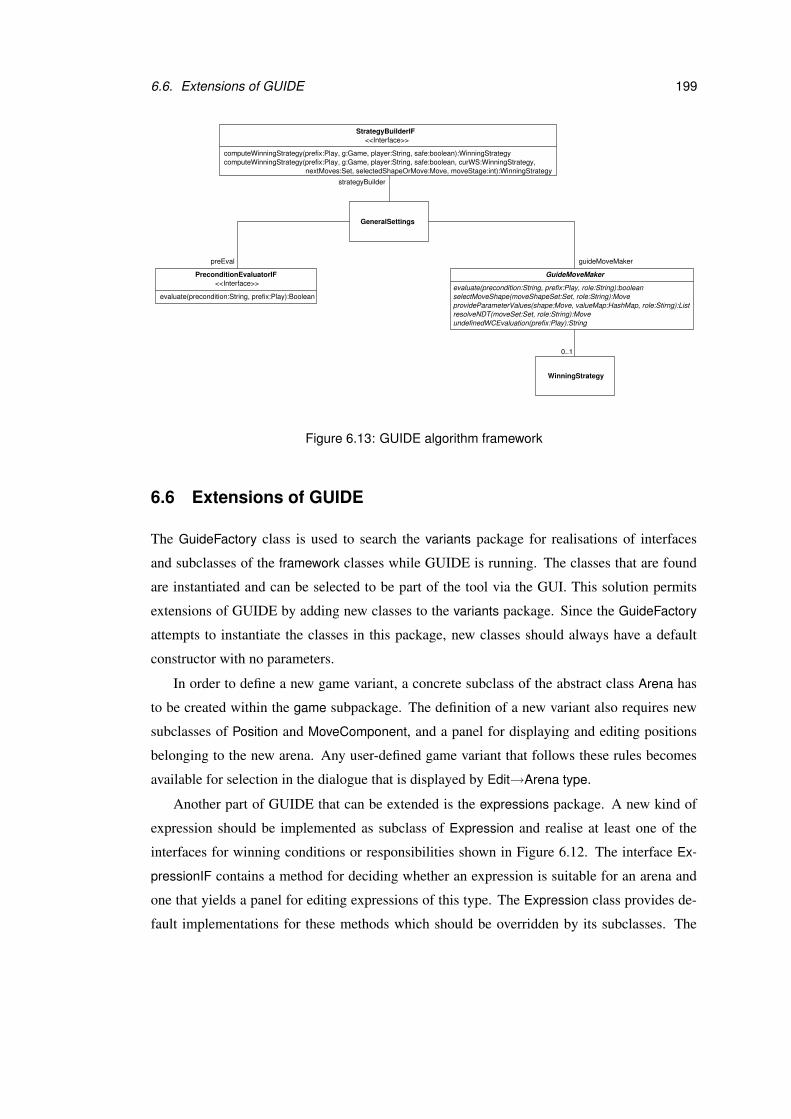
6.6. Extensions of GUIDE 199
<<Interface>>
computeWinningStrategy(prefix:Play, g:Game, player:String, safe:boolean):WinningStrategycomputeWinningStrategy(prefix:Play, g:Game, player:String, safe:boolean, curWS:WinningStrategy,
nextMoves:Set, selectedShapeOrMove:Move, moveStage:int):WinningStrategy
StrategyBuilderIF
<<Interface>>
WinningStrategy
0..1
GeneralSettings
selectMoveShape(moveShapeSet:Set, role:String):Move
resolveNDT(moveSet:Set, role:String):MoveprovideParameterValues(shape:Move, valueMap:HashMap, role:Stirng):List
GuideMoveMaker
evaluate(precondition:String, prefix:Play, role:String):boolean
PreconditionEvaluatorIF
evaluate(precondition:String, prefix:Play):Boolean
undefinedWCEvaluation(prefix:Play):String
strategyBuilder
guideMoveMakerpreEval
Figure 6.13: GUIDE algorithm framework
6.6 Extensions of GUIDE
The GuideFactory class is used to search the variants package for realisations of interfaces
and subclasses of the framework classes while GUIDE is running. The classes that are found
are instantiated and can be selected to be part of the tool via the GUI. This solution permits
extensions of GUIDE by adding new classes to the variants package. Since the GuideFactory
attempts to instantiate the classes in this package, new classes should always have a default
constructor with no parameters.
In order to define a new game variant, a concrete subclass of the abstract class Arena has
to be created within the game subpackage. The definition of a new variant also requires new
subclasses of Position and MoveComponent, and a panel for displaying and editing positions
belonging to the new arena. Any user-defined game variant that follows these rules becomes
available for selection in the dialogue that is displayed by Edit→Arena type.
Another part of GUIDE that can be extended is the expressions package. A new kind of
expression should be implemented as subclass of Expression and realise at least one of the
interfaces for winning conditions or responsibilities shown in Figure 6.12. The interface Ex-
pressionIF contains a method for deciding whether an expression is suitable for an arena and
one that yields a panel for editing expressions of this type. The Expression class provides de-
fault implementations for these methods which should be overridden by its subclasses. The
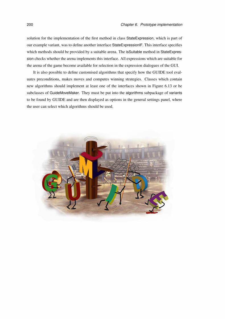
200 Chapter 6. Prototype implementation
solution for the implementation of the first method in class StateExpression, which is part of
our example variant, was to define another interface StateExpressionIF. This interface specifies
which methods should be provided by a suitable arena. The isSuitable method in StateExpres-
sion checks whether the arena implements this interface. All expressions which are suitable for
the arena of the game become available for selection in the expression dialogues of the GUI.
It is also possible to define customised algorithms that specify how the GUIDE tool eval-
uates preconditions, makes moves and computes winning strategies. Classes which contain
new algorithms should implement at least one of the interfaces shown in Figure 6.13 or be
subclasses of GuideMoveMaker. They must be put into the algorithms subpackage of variants
to be found by GUIDE and are then displayed as options in the general settings panel, where
the user can select which algorithms should be used.

Chapter 7
Discussion
The development of the game concepts and implementation of the GUIDE tool which have
been presented in this thesis required decisions at many points. In this chapter we justify some
of the choices that have been made and discuss possible alternatives. We begin with a con-
sideration of the idea that the game definition contains both the design and specification of a
system. This is followed by an explanation of the relationship between exploration games and
model checking approaches. After that we discuss an alternative to move steps and the explo-
ration game framework’s restrictions concerning parameters in preconditions. With respect to
the application of the framework to UML we outline how inheritance and recursive calls could
be treated in exploration game variants. For the prototype implementation based on exploration
games we justify our decision to develop a stand-alone tool.
7.1 General approach
A possible objection to the general approach of using games for UML software design as it
was presented in this thesis is that there is no clean separation between the design and its spec-
ification. If the specification is incorporated into the game definition, which also incorporates
a particular design, does this not lose clarity and prevent a separate evaluation of the specifica-
tion?
If we look at the game variants that have been introduced in chapter 5, we can make an
interesting observation: the system’s specification and design are located in different parts
of the game definition and can be identified relatively easily. For property checking games
the specification is expressed by the winning conditions. In case of comparison games the
201

202 Chapter 7. Discussion
specification is contained in the desired relationship between the UML diagrams that form the
basis of the game.
The game variants that have been presented in this thesis are just a small selection of ex-
amples. It remains an open question if there is in fact always a clear distinction between design
and specification in the game definition. Further investigation about what games people build
in practice would be needed to give a definite answer to this question. A publicly available
tool like GUIDE is helpful in this context, because it encourages users to suggest new game
variants, or even to add them themselves.
Another answer to the objection that design and specification are not clearly separated
would be to say that this is not important at the design level. A specification that is independent
of the design is a realistic aim at a high level, where the user requirements are being expressed
in the user’s vocabulary. Inevitably, though, the verification of a design is done against a more
detailed, technical requirements specification that always incorporates many assumptions about
the design, even when it is presented as a separate document or UML package.
The purpose of the approach presented in this thesis is to help the designer with transform-
ing a system model that is not precise enough to be verified formally into one that is more
detailed. The focus of exploration games is not on verifying formally that a design is cor-
rect. Instead exploration games complement, prepare and build on traditional model checking
approaches.
In contrast to traditional two-player games as used in verification, exploration games let the
game participants resolve uncertain situations and permit incrementations of the game defini-
tion by the Explorer while the game is being played. These features allow a game to be based
directly on a possibly partial and informal UML model. By repeated incrementations the mod-
eller gradually adds more detail to the design and its specification. If the Explorer continues
this process until the game can be played automatically, the exploration game corresponds to a
model-checking game. This is a special case and we believe that the exploration does not have
to be taken so far and can be stopped at an earlier point for most mainstream software systems.
Checking the current design model against the current specification while the game is being
played gives the designer ideas for improving both parts. Techniques and algorithms known
from model checking provide a valuable foundation for this purpose. They may serve as general
resources for computational problems related to exploration games and can often be adapted
such that they respect responsibilities and informal preconditions of moves.

7.2. Exploration game framework 203
7.2 Exploration game framework
In our exploration game framework a move consists of four steps which may be performed
by different game participants. This approach has been chosen because the positions of the
game remain on a high level of abstraction which has been sufficient for the game variants
considered here. An alternative would be to treat each step as a separate move. In this case
intermediate positions which record the results of each move step would be needed. This
opens up new possibilities for specifying winning conditions and preconditions, because the
intermediate positions become part of the play history. For example, a player could be assigned
responsibility for selecting the next move shape at all positions where less than 5 move shapes
have been declared as legal in the previous move. However, this expressiveness comes at the
price of more complex position definitions and a greater number of positions in the arena.
A restriction of exploration games is that the move preconditions may only refer to param-
eters that are known at the move’s source position, otherwise the precondition evaluation is
undefined. If move preconditions were allowed to refer to parameters whose values have not
been provided yet, the order of the move steps would have to be changed. The game partici-
pants would have to select a move shape and provide parameters for it first. Only after these
steps have taken place could be decided whether the chosen move shape is legal under the pro-
vided parameter values. That means a move shape might turn out to be illegal after it has been
selected. The play history does not contain the result of the parameter provision which may
have affected the move’s precondition evaluation, i.e. a possibly important aspect of the play
is not recorded.
In the more restrictive approach that we have chosen in this thesis, the move shapes that
are selected by the game participants are always legal because their preconditions are evaluated
earlier. If the game participants provide parameter values which prevent the choice of a specific
move later in the play, all necessary information for analysing why this move is not allowed at
a certain point can be found in the play history.
7.3 Application to UML
The purpose of the game variants that have been introduced in this thesis is to illustrate that
the exploration game framework is general enough to be applied in various ways. Thus we
have decided to leave out some detail and did not cover all features of the UML diagrams
that were used in the game variants. We have also not considered the general concept of

204 Chapter 7. Discussion
inheritance explicitly in this thesis. For state machines, which are relevant for most of the
variants discussed here, the UML specification does not contain much detail on this topic. The
relationship between two state machines that refer to a class and to one of its subclasses is
not precisely defined. A simple solution would be to regard state machines with these class
contexts separately and record state configurations for both of them in the game’s positions for
objects of the subclass. The events that arrive at these objects are then always processed by
both state machines.
Another issue that is not covered sufficiently in the UML specification and has therefore
not been considered here in detail are recursive calls in or between state machines. Recursion
can occur in all game variants where the execution of activities during a transition leads to the
generation of new events, such as in our example variants A, C and E. If the activities which
form a recursive cycle are synchronous invocations, they cause deadlocks. These deadlocks
occur because the UML specification defines that an object cannot process an event if it is
waiting for the completion of a synchronous call. The UML standard seems to encourage the
usage of activity diagrams for modelling recursion, but does not state explicitly that recursion
should be avoided in state machines. For our game variants we have introduced a setting which
allows recursive synchronous invocations to be ignored and discarded.
In [TS03] the problem of modelling recursive calls is discussed in detail for an older ver-
sion of UML. The solution proposed there is based on two kinds of state machines which are
used in a complementary way. UML protocol state machines model the overall effect of meth-
ods on objects and method state machines specify in detail which actions are part of method
executions. Method state machines change the concrete state of objects and can be invoked
by a protocol state machine or by each other. A mapping between concrete object states and
protocol states is used to decide whether the invocation of a method state machine respects
the protocol. Since the concrete object states are always known, the legality of a method state
machine invocation can always be determined, no matter if the method call is recursive or not.
The ideas of [TS03] could be used to define an exploration game variant which treats re-
cursive calls in a similar manner. Instead of method state machines UML2.0 activity diagrams
could be used. The main problem with this approach are informally defined actions, which are
often mixed with formally defined method invocations in UML activity diagrams. After the ex-
ecution of an informal action the concrete object states are undefined. They must be specified
manually by the modeller each time before a method is invoked. The concrete object states are
needed in order to use the mapping to protocol states. If they are not precisely defined at the

7.4. Prototype implementation 205
time of an invocation, it is impossible to decide whether this invocation is legal, because the
corresponding protocol state cannot be determined.
7.4 Prototype implementation
The intention of implementing a prototype was to demonstrate that exploration games are a
useful basis for a UML design tool that supports interactive design exploration. Thus our
prototype tool GUIDE has a different focus than any other available UML design tool. An
obvious question is why GUIDE has been implemented as a stand-alone tool and not as a
plug-in or module for an existing UML tool.
The first idea for providing prototypical tool support was in fact to extend the ArgoUML
tool [Arg], which is probably the most widely used open source UML tool. We have experi-
mented with implementing protocol state machines as an ArgoUML module but this extension
has been more difficult than expected. This was mainly caused by ArgoUML’s architecture and
strong dependency on other components. Our simple extension already required changes and
debugging in different subpackages and libraries used by ArgoUML.
There exist some other UML tools which are not open source but permit extension by
modules or plug-ins, such as for example Poseidon [Pos] and Together [Tog]. Both tools can
be accessed via interfaces, which are fixed by the tool vendor. The risk of using this approach
is that the interfaces may turn out not to be sufficient for the desired extension. For example,
backtracking in the play history and restoring the previous model version as implemented in
the GUIDE tool requires a method for loading a UML model via the interface, which none of
the tools we have looked at provided at this time.
As a result of this investigation we have chosen the stand-alone solution for GUIDE. The
advantage of this approach is that it is very flexible and not bound to one particular tool. The
drawback is that GUIDE does not contain a graphic editor for UML diagrams, whose imple-
mentation was not in the scope of this thesis. It is often difficult to follow the changes of the
state configurations during a play without a printout of the state machine diagrams. The rep-
resentation of the model as a tree is not a sufficient substitute for the diagrammatic notation
when larger UML models are considered.
As storage mechanism for the UML model in our tool we have used the Metadata Reposi-
tory (MDR) by NetBeans [MDR]. The MDR project is aimed at persistent storage and manip-
ulation of metadata. It is based on the Meta Object Facility (MOF) standard [MOF02]. The
solution based on MDR has two main advantages. First, different UML tools can be supported
206 Chapter 7. Discussion
because MDR is not bound to a particular XMI version or tool-specific saving format. That
means the XMI output of any UML tool that is compliant with the UML1.4 metamodel can be
read into GUIDE. Second, MDR’s interfaces for accessing and manipulating the UML model
have reduced the amount of code that had to be written. The drawback of this solution is its
performance. Creating a fresh instance of the metamodel and reading the contents of an XMI
file into it takes a few seconds during which the user cannot perform any other tasks with the
GUIDE tool.
Chapter 8
Conclusion
In this thesis we have introduced a game-based approach for the exploration of UML software
design. The designer repeatedly plays an exploration game to gradually add more detail to the
system’s design and specification in the role of the Explorer. He can also take on the roles of
other game participants to examine the design from a particular view. While a game is being
played, non-determinacy is resolved by the game participants. That means, an exploration
game may be based on a UML model that is incomplete or informally defined. The definition
of the game and the progress of a play can be “tuned” by various settings. Moreover the
responsibilities for particular parts of a move may be distributed flexibly among the game
participants. If Refuter wins a play, design and specification do not fit each other under the
current game settings. The play serves as a counter-example and may give the modeller an idea
about how to increment the game as Explorer in response to this discovery. Proving that design
and specification match corresponds to finding a winning strategy for Verifier.
The exploration game framework, which has been developed in this thesis, has been ap-
plied to UML in different variations. We have distinguished property checking games for the
evaluation of a design solution with respect to a set of properties, and comparison games for the
examination of the relationship between different UML diagrams. The focus of the example
game variants in this thesis has been on UML state machines.
The concept of exploration games has been used as foundation for our prototype imple-
mentation GUIDE. One of the game variants presented in this thesis has been implemented in
the GUIDE tool as an example. The tool supports the designer in setting up and playing a game
of this variant. Most of the general and variant-specific settings that have been introduced in
the conceptual part of this thesis are available in GUIDE. Furthermore a general expression
207
208 Chapter 8. Conclusion
framework for the definition of winning conditions and responsibility assignments is part of
the tool. GUIDE also provides default algorithms for computing winning strategies, evaluating
preconditions and making moves on behalf of the players. The architecture of our prototype
permits extension by additional game variants and alternative algorithms.
Since this thesis is the first work on using games for design exploration, it covers a broad
range of topics. We have developed exploration games as formal basis for our approach, applied
them to UML software design in different variations, and implemented a prototype tool to
demonstrate that the ideas presented in this thesis can be put into practice. These contributions
can serve as foundation for a new direction of research and provide plenty of opportunities for
future work.
Probably the most important task is to give users the opportunity to exercise our proto-
type tool and to analyse their feedback. Thereby it would be possible to identify which parts
of the approach presented here are most interesting in practice and where improvements are
necessary. Experiments with students could be used as first step for testing GUIDE before
advertising it to a wider community. More advanced investigations could focus on the com-
parison of exploring a design using the GUIDE tool with traditional techniques such as design
reviews.
On the theoretical side the computation of winning strategies for exploration games could
be considered in more depth. The algorithm that we have used for GUIDE is a simple depth-
first search algorithm, which only works for finite game arenas. We have enforced finiteness by
restricting the possible parameter values to a fixed set and by the introduction of a move limit.
Existing work on verification of systems with infinite state spaces could be used to develop a
solution for exploration games with infinite arenas.
Instead of computing a winning strategy completely upfront, we could also develop and
modify it during a play. A technique that is used in computer chess is “to look n steps ahead”.
The game tree is built up in full width until depth n is reached and is further extended after
each move. In order to allow the computation of a winning strategy for a player each position
is labelled by a value. The value represents “how good” the position is for the player under
consideration. The difficulty is to define a useful evaluation function to create this labelling.
With respect to exploration games we would expect that a sophisticated evaluation function
must be defined for a concrete game variant rather than the framework itself.
In our example applications of the exploration game framework we have concentrated on a
small subset of UML’s model elements. Future work could attempt to cover more of the omitted

209
features or new combinations of UML diagrams. In fact, we believe that the exploration game
framework is general enough to be applied to other modelling languages as well. Examination
of a wider range of applications could provide insights into the limits of the framework.
Once the basic functionality of GUIDE has been tested on users, the extension mechanism
of the tool could be used to experiment with more advanced algorithms. For example, pre-
condition evaluation could be performed in collaboration with a tool that can evaluate OCL
constraints. If the designer commits himself to use OCL in the UML model, some of the
move preconditions may then be evaluated automatically and do not require interaction with
the game participants during a play. New algorithms for computing winning strategies and
making moves on behalf of the game participants could also be integrated into GUIDE. We
have already mentioned “looking ahead” and heuristics as possibilities for improving the com-
putation of winning strategies. These techniques could also help GUIDE to move reasonably
for the game participants in general, even if there exist no winning strategies.
In this thesis we have assumed that it is always the designer who plays the Explorer and
increments the game. It is undoubtedly fascinating to imagine that the tool could perform the
exploration of the design. However, the exploration generally requires knowledge about the
system and design skills. We expect that building a tool which performs the tasks of a designer
to a certain degree would involve a large amount of research in the area of artificial intelligence.
The GUIDE tool does not aim at substituting the designer, but at supporting him in using his
skills. A very advanced version of GUIDE could try to give the designer feedback about which
kind of incrementation is beneficial for a player in specific situations. However, it is then still
the designer who has to make a concrete incrementation according to the tool’s suggestion.
Figure 8.1: The fun of playing “Calvinball”. This figure was taken from [Cal].

Bibliography
[ABB+05] W. Ahrendt, T. Baar, B. Beckert, R. Bubel, M. Giese, R. Hahnle, W. Menzel,W. Mostowski, A. Roth, S. Schlager, and P. H. Schmitt. The KeY tool. Softwareand System Modeling, 4:32–54, 2005.
[AH94] R.J. Aumann and S. Hart, editors. Handbook of Game Theory with EconomicApplications. Elsevier Science, 1994.
[ALW89] M. Abadi, L. Lamport, and P. Wolper. Realizable and unrealizable specificationsof reactive systems. In Proceedings of the 16th International Colloquium on Au-tomata, Languages and Programming, ICALP’89, volume 372 of LNCS, pages1–17. Springer, 1989.
[AM] Agile Modeling. Website at http://www.agilemodeling.com.
[Ant] The Apache Ant Project. Website at http://ant.apache.org.
[Arg] The ArgoUML Project, version 0.14. Website athttp://argouml.tigris.org.
[ASL01] UML ASL reference guide, 2001. Available from the Kennedy Carter Limitedat http://www.kc.com.
[BC89] K. Beck and W. Cunningham. A laboratory for teaching object-oriented thinking.ACM SIGPLAN Notices, 24(10):1–6, October 1989.
[BCR02] E. Borger, A. Cavarra, and E. Riccobene. A precise semantics of UML statemachines: making semantic variation points and ambiguities explicit. In Pro-ceedings of Semantic Foundations of Engineering Design Languages, SFEDL,Satellite Workshop of ETAPS’02, 2002.
[Bec99] K. Beck. Extreme Programming Explained: Embrace Change. Addison-WesleyPublishing, 1999.
[BFS02] J. Bradfield, J. Kuster Filipe, and P. Stevens. Enriching OCL using observationalmu-calculus. In Proceedings of Fundamental Approaches to Software Engineer-ing, FASE’02, volume 2306 of LNCS, pages 203–217. Springer, 2002.
[Bin92] K. Binmore. Fun and Games: A Text on Game Theory. D.C. Heath and Com-pany, 1992.
211
212 Bibliography
[BL69] J. Buchi and L. Landweber. Solving sequential conditions by finite-state strate-gies. Transactions of the American Mathematical Society, 138:295–311, April1969.
[Boc03a] C. Bock. UML 2 activity and action models. Journal of Object Technology,2(4):43–53, 2003.
[Boc03b] C. Bock. UML 2 activity and action models part 2: Actions. Journal of ObjectTechnology, 2(5):41–56, 2003.
[Boc03c] C. Bock. UML 2 activity and action models part 3: Control nodes. Journal ofObject Technology, 2(6):7–23, 2003.
[Boc04] C. Bock. UML 2 activity and action models part 4: Object nodes. Journal ofObject Technology, 3(1):27–41, 2004.
[Boo91] G. Booch. Object Oriented Analysis and Design with Applications. Ben-jamin/Cummings, 1991.
[BRJ98] G. Booch, J. Rumbaugh, and I. Jacobson. The Unified Modeling Language UserGuide. Addison Wesley Longman, 1998.
[Cal] The Unofficially Official Rules of Calvinball. Available fromhttp://www.geocities.com/SoHo/Nook/2990/cb_rules.htm.The comic series Calvin and Hobbes was created by B. Watterson.
[CGP99] E. M. Clarke, Jr., O. Grumberg, and D. A. Peled. Model Checking. The MITPress, 1999.
[Chu63] A. Church. Logic, arithmetic, and automata. In Proceedings of the InternationalCongress of Mathematicians 1962. Almquist & Wiksells, 1963.
[CMP91] E. Chang, Z. Manna, and A. Pnueli. The safety-progress classification. In F.L.Bauer, W. Brauer, and H. Schwichtenberg, editors, Logic and Algebra of Spec-ification, NATO Advanced Science Institutes Series, pages 143–202. Springer,1991.
[Coc02] A. Cockburn. Agile Software Development. Addison-Wesley, 2002.
[dAHK98] L. de Alfaro, T. A. Henzinger, and O. Kupferman. Concurrent reachabilitygames. In Proceedings of Foundations of Computer Science, FOCS’98, pages564–575. IEEE Press, 1998.
[dAHM00] L. de Alfaro, T.A. Henzinger, and F.Y.C. Mang. The control of synchronoussystems. In Proceedings of Concurrency Theory, CONCUR’00, volume 1877 ofLNCS, pages 92–107. Springer, 2000.
[dAHM01a] L. de Alfaro, T. A. Henzinger, and R. Majumdar. From verification to con-trol: Dynamic programs for omega-regular objectives. In Proceedings of theIEEE Symposium on Logic in Computer Science, LICS’01, pages 279–290. IEEEComputer Society Press, 2001.

Bibliography 213
[dAHM01b] L. de Alfaro, T.A. Henzinger, and F.Y.C. Mang. The control of synchronoussystems part II. In Proceedings of Concurrency Theory, CONCUR’01, LNCS.Springer, 2001.
[Dia] Dia, version 0.92.2. Website at http://www.gnome.org/projects/dia.
[DL87] T. DeMarco and T. Lister, editors. Peopleware - Productive Projects and Teams.Dorset House Publishing, 1987.
[dMGMP02] M. del Mar Gallardo, P. Merino, and E. Pimentel. Debugging UML designswith model checking. Journal of Object Technology, 1(2):101–117, July-August2002.
[Edi] Edinburgh Concurrency Workbench. Available from Laboratory for Foundationsof Computer Science, University of Edinburgh. Website athttp://www.dcs.ed.ac.uk/home/cwb.
[EF95] H.-D. Ebbinghaus and J. Flum. Finite Model Theory. Springer, 1995.
[ERRW03] H. Ehrig, W. Reisig, G. Rozenberg, and H. Weber, editors. Petri Net Technologyfor Communication-Based Systems: Advances in Petri Nets, volume 2472 ofLNCS. Springer, 2003.
[FA03] J. Kuster Filipe and S. Anderson. Using OCL for expressing temporal validityconstraints. In Proceedings of the International Workshop on Specification andValidation of UML models for Real Time and Embedded Systems, SVERTS’03,2003.
[Fag76] M. Fagan. Design and code inspections to reduce errors in program development.IBM Systems Journal, 15(3), 1976.
[Fow04] M. Fowler. UML distilled: a brief guide to the standard object modeling lan-guage. Addison-Wesley, third edition, 2004.
[Fra02] A.S. Fraenkel. Selected bibliography on combinatorial games and some relatedmaterial. The Electronic Journal of Combinatorics, Dynamic Survey 2(DS2),2002. Available from http://www.combinatorics.org/Surveys/ds2.ps.
[FS03] J. Feigenbaum and S. Shenker. Distributed algorithmic mechanism design: re-cent results and future directions. Bulletin of the EATCS, Distributed ComputingColumn, 79:101–121, 2003.
[Fuj] Fujaba Tool Suite, version 4.1.0. Website at http://www.fujaba.de.
[GPB02] D. Giannakopoulou, C.S. Pasareanu, and H. Barringer. Assumption generationfor software component verification. In Proceedings of Automated Software En-gineering, ASE’02, pages 3–12. IEEE Computer Society, 2002.

214 Bibliography
[GPP98] M. Gogolla and F. Parisi-Presicce. State diagrams in UML: A formal semanticsusing graph transformations. In Proceedings of the Workshop on Precise Se-mantics for Modeling Techniques, PSMT’98. Technische Universitat Munchen,TUM-I9803, 1998.
[GTW02] E. Gradel, W. Thomas, and T. Wilke, editors. Automata, Logics, and InfiniteGames: A Guide to Current Research, volume 2500 of LNCS. Springer, 2002.
[Gui] GUIDE - Games with UML for Interactive Design Exploration. Available fromthe author’s homepage at http://www.lfcs.informatics.ed.ac.uk/jnt.
[Hal03] J. Y. Halpern. A computer scientist looks at game theory. Games and EconomicBehavior, 45(1):114–131, 2003.
[Har87] D. Harel. Statecharts: A visual formalism for complex systems. Science ofComputer Programming, 8:231–272, 1987.
[Har01] D. Harel. From play–in scenarios to code: An achievable dream. IEEE Com-puter, 342(1):53–60, January 2001.
[HG97] D. Harel and E. Gery. Executable object modeling with statecharts. IEEE Com-puter, 30:7:31–42, 1997.
[HKMP02] D. Harel, H. Kugler, R. Marelly, and A. Pnueli. Smart play-out of behavioralrequirements. In Proceedings of Formal Methods in Computer-Aided Design,FMCAD’02, pages 378–398, 2002.
[Hod93] W. Hodges. Model theory, volume 42 of Encyclopedia of Mathematics and itsApplications. Cambridge University Press, Cambridge, 1993.
[HPSS87] D. Harel, A. Pnueli, J. Schmidt, and R. Sherman. On the formal semanticsof statecharts. In Proceedings of the IEEE Symposium on Logic in ComputerScience, LICS’87, pages 54–64. IEEE, 1987.
[Hug] Hugo/RT. Website athttp://www.pst.informatik.uni-muenchen.de/projekte/hugo.
[Hum95] W. S. Humphrey. A Discipline for Software Engineering. Addison-Wesley, 1995.
[Ico] Leo’s Icon Archive. Website at http://www.iconarchive.com.
[IMP01] P. Inverardi, H. Muccini, and P. Pelliccione. Automated check of architecturalmodels consistency using SPIN. In Proceedings of Automated Software Engi-neering, ASE’01, pages 346–349. IEEE Computer Society, 2001.
[IT01] P. Inverardi and M. Tivoli. Automatic synthesis of deadlock free connectors forCOM/DCOM applications. In Joint Proceedings of European Software Engi-neering Conference, ESEC’01 and ACM SIGSOFT Symposium on the Founda-tions of Software Engineering, FSE’01, pages 121–131. ACM Press, 2001.

Bibliography 215
[Java] Java 2 Platform, Standard Edition (J2SE), version 1.4.2. Website athttp://java.sun.com/j2se.
[Javb] Javadoc 1.4.2 Tool. Website athttp://java.sun.com/j2se/1.4.2/docs/tooldocs/javadoc.
[JBR99] I. Jacobson, G. Booch, and J. Rumbaugh. The Unified Software DevelopmentProcess. Addison Wesley, 1999.
[JCJO92] I. Jacobson, M. Christerson, P. Jonsson, and G. Overgaard. Object-OrientedSoftware Engineering: A Use Case Driven Approach. Addison-Wesley, 1992.
[Jen97] K. Jensen. Coloured Petri Nets. Basic Concepts, Analysis Methods and PracticalUse. Volume 1-3. Monographs in Theoretical Computer Science. Springer, 1997.
[KE01] N. Kaveh and W. Emmerich. Deadlock detection in distributed object systems.In Joint Proceedings of European Software Engineering Conference, ESEC’01and ACM SIGSOFT Symposium on the Foundations of Software Engineering,FSE’01, pages 44–51. ACM Press, 2001.
[KeY] The KeY Project. Website at http://www.key-project.org.
[KM02] A. Knapp and S. Merz. Model checking and code generation for UML statemachines and collaborations. In 5th Workshop on Tools for System Design andVerification, FM-TOOLS’02, Report 2002-11. Institut fur Informatik, UniversitatAugsburg, 2002.
[KMF] The Kent Modelling Framework. Available from the University of Kent athttp://www.ukc.ac.uk/kmf.
[KMTV00] O. Kupferman, P. Madhusudan, P.S. Thiagarajan, and M.Y. Vardi. Open systemsin reactive environments: control and synthesis. In Proceedings of ConcurrencyTheory, CONCUR’00, volume 1877 of LNCS, pages 92–107. Springer, 2000.
[Kru01] P. Kruchten. What is the Rational Unified Process?, 2001.
[Kus01] S. Kuske. A formal semantics of UML state machines based on structured graphtransformation. In Proceedings of the International Conference on the UnifiedModeling Language, UML’01, volume 2185 of LNCS, pages 241–256. Springer,2001.
[KV99] O. Kupfermann and M.Y. Vardi. Church’s problem revisited. The Bulletin ofSymbolic Logic, 5(2):245–263, June 1999.
[KV01] O. Kupferman and M.Y. Vardi. Synthesising distributed systems. In Proceed-ings of the IEEE Symposium on Logic in Computer Science, LICS’01. IEEEComputer Society, June 2001.

216 Bibliography
[Kwo00] G. Kwon. Rewrite rules and operational semantics for model checking UMLstatecharts. In Proceedings of the International Conference on the Unified Mod-eling Language, UML’00, volume 1939 of LNCS, pages 528–540. Springer,2000.
[Lan02] M. Lange. Games for Modal and Temporal Logics. PhD thesis, University ofEdinburgh, 2002.
[LMM99] D. Latella, I. Majzik, and M. Massink. Towards a formal operational seman-tics of UML statechart diagrams. In Proceedings of Formal Methods for OpenObject-Based Distributed Systems, FMOODS’99, volume 139 of IFIP. Kluwer,1999.
[Log] Log4j Project. Website at http://logging.apache.org/log4j.
[LP99] J. Lilius and I. Porres. vUML: A tool for verifying UML models. In Proceedingsof Automated Software Engineering, ASE’99. IEEE, 1999.
[Mar75] D. A. Martin. Borel determinacy. The Annals of Mathematics, 102(2):363–371,September 1975.
[MC01] W. E. McUmber and B. H. C. Cheng. A general framework for formalizingUML with formal languages. In Proceedings of the International Conferenceon Software Engineering, ICSE 2001, pages 433–442. IEEE Computer Society,2001.
[MDR] NetBeans Metadata Repository (MDR). Website athttp://mdr.netbeans.org.
[Mil] P. Milne. Using XMLEncoder. Sun Developer Network. Available fromhttp://java.sun.com/products/jfc/tsc/articles/persistence4.
[Mil89] R. Milner. Communication and Concurrency. Prentice Hall, 1989.
[MOF02] Meta-Object Facility (MOF, version 1.4, document formal/02-04-03), April2002. Available from the OMG at http://www.omg.org.
[MT02] P. Madhusudan and P.S. Thiagarajan. Branching time controllers for discreteevent systems. Theoretical Computer Science, 274(1–2):117–149, 2002.
[Net] NetBeans IDE, version 3.6. Website at http://www.netbeans.org.
[Obj] Objecteering/UML, version 5.2.3. Available from Objecteering Software athttp://www.objecteering.com.
[OCL03] UML 2.0 OCL Final Adopted specification, October 2003. Available from theOMG at http://www.omg.org/uml.
[Pos] Poseidon for UML, version 3.0. Available from Gentleware athttp://www.gentleware.com.
Bibliography 217
[PR89] A. Pnueli and R. Rosner. On the synthesis of a reactive model. In SixteenthAnnual ACM Symposium on Principles of Programming Languages, POPL’89.ACM Press, 1989.
[pUM] The Precise UML Group. Website at http://www.cs.york.ac.uk/puml.
[Rab72] M.O. Rabin. Automata on infinite objects and Church’s problem. RegionalConference Series in Mathematics, 13, 1972.
[RACH00] G. Reggio, E. Astesiano, C. Choppy, and H. Hussmann. Analysing UML activeclasses and associated state machines - A lightweight formal approach. In Pro-ceedings of Fundamental Approaches to Software Engineering, FASE’00, vol-ume 1783 of LNCS, pages 127–146. Springer, 2000.
[Rat] Rational XDE Developer Plus for Java, version 2003.06.12. Available from IBMat http://www.rational.com.
[RBL+90] J. Rumbaugh, M. Blaha, W. Lorensen, F. Eddy, and W. Premerlani. Object-Oriented Modeling and Design. Prentice Hall, 1990.
[Rea] Real Time Studio professional, version 4.3. Available from Artisan Software athttp://www.artisansw.com.
[RG99] M. Richters and M. Gogolla. A metamodel for OCL. In Proceedings of the 2ndInternational Conference on the Unified Modeling Language, UML’99, volume1723 of LNCS, pages 156–171. Springer, 1999.
[RGG98] M. Richters, M. Gogolla, and H. Gartner. On formalizing the UML object con-straint language OCL. In Conceptional Modeling, ER’98, volume 1507 of LNCS,pages 449–464. Springer, 1998.
[Rha] Rhapsody, version 5.0. Available from I-Logix at http://www.ilogix.com.
[Ric02] M. Richters. A Precise Approach to Validating UML Models and OCL Con-straints. PhD thesis, Universitat Bremen, Logos Verlag, Berlin, BISS Mono-graphs, No. 14, 2002.
[Rob99] J. E. Robbins. Cognitive Support Features for Software Development Tools. PhDthesis, University of California, Irvine, 1999.
[SDL] ITU-T standard Z.100 and Z.105. Available from the International Telecommu-nication Union (ITU) at http://www.itu.int.
[Ser04] O. Serre. Games with winning conditions of high Borel complexity. In Pro-ceedings of the 31st International Colloquium on Automata, Languages, andProgramming, ICALP’04, volume 3142 of LNCS, pages 1150–1162. Springer,2004.
[Sma] SmartDraw, version 3.5.1. Website at http://www.smartdraw.com.
218 Bibliography
[Som04] I. Sommerville. Software Engineering. Addison Wesley, Seventh edition, 2004.The insulin pump case study is also described in various documents at the book’swebpage at http://www.software-engin.com/.
[SP99] P. Stevens and R. Pooley. Using UML: Software Engineering with Objects andComponents. Addison Wesley Longman, 1999.
[SS98] P. Stevens and C. Stirling. Practical model-checking using games. In Tools andAlgorithms for Construction and Analysis of Systems, TACAS’98, volume 1384of LNCS. Springer, 1998.
[ST03] P. Stevens and J. Tenzer. Games for UML software design. In Formal Methodsfor Components and Objects, FMCO’02, volume 2852 of LNCS. Springer, 2003.
[Ste98a] P. Stevens. Abstract games for infinite state processes. In Proc. 9th Inter-national Conference on Concurrency Theory, CONCUR’98, number 1466 inLNCS, pages 147–162. Springer-Verlag, 1998.
[Ste98b] P. Stevens. Abstract interpretations of games. In Proceedings of the Workshop onVerification, Model Checking and Abstract Interpretation, VMCAI’98, numberCS98-12 in Venezia TR, 1998.
[Sti96] C. Stirling. Model checking and other games. Notes for Mathfit Workshop onfinite model theory, University of Wales, Swansea, July 1996.
[TB73] B.A. Trakhtenbrot and Y. M. Barzdin. Finite automata: Behavior and synthesis.North-Holland, 1973.
[Ten04a] J. Tenzer. Exploration games for safety-critical system design with UML 2.0. InProceedings of the 3rd International Workshop on Critical Systems Developmentwith UML, CSDUML’04, Technical Report I0415, pages 41–55. Technische Uni-versitat Munchen, September 2004.
[Ten04b] J. Tenzer. Improving UML design tools by formal games. In Proceedings ofthe International Conference on Software Engineering, ICSE’04, pages 75–77.IEEE Computer Society, 2004. Research abstract for the ICSE doctoral sympo-sium.
[Ten05a] J. Tenzer. Exploration games with UML software design. In Proceedings of the5th Annual DIRC Research Conference, DIRC’05, pages 178–179. LancasterUniversity Press, 2005.
[Ten05b] J. Tenzer. GUIDE: Games with UML for interactive design exploration. InProceedings of the 4th International Conference on Software Methodologies,Tools, and Techniques, SoMeT’05., pages 364–387. IOS Press, 2005.
[Tho95] W. Thomas. On the synthesis of strategies in infinite games. In Proceedings ofthe Symposium on Theoretical Aspects of Computer Science, STACS’95, volume900 of LNCS, pages 1–13. Springer, 1995.

Bibliography 219
[Tho02] W. Thomas. Infinite games and verification. In Computer Aided Verification,CAV’02, volume 2404 of LNCS. Springer, 2002.
[Tog] Together Control Centre, version 6.1. Available from Borland athttp://www.borland.com/together.
[TS03] J. Tenzer and P. Stevens. Modelling recursive calls with UML state diagrams.In Proceedings of Fundamental Approaches to Software Engineering, FASE ’03,volume 2621 of LNCS, pages 135–149. Springer, April 2003.
[TS05] J. Tenzer and P. Stevens. On modelling recursive calls and callbacks with twovariants of Unified Modeling Language state diagrams, 2005. Journal version ofthe paper presented at FASE’03. Accepted for publication in Formal Aspects ofComputing.
[UKM04] S. Uchitel, J. Kramer, and J. Magee. Incremental elaboration of scenario-basedspecifications and behavior models using implied scenarios. ACM Transactionson Software Engineering and Methodology, 13(1):37–85, 2004.
[UML01] OMG Unified Modeling Language Specification, version 1.4, documentformal/01-09-67, September 2001. Available from the OMG athttp://www.omg.org.
[UML03a] OMG Unified Modeling Language Specification, version 1.5, documentformal/03-03-01, March 2003. Available from the OMG athttp://www.uml.org.
[UML03b] UML 2.0 Superstructure Final Adopted Specification, document ptc/03-08-02,August 2003. Available from the OMG at http://www.uml.org.
[UML03c] UML 2.0 Diagram Interchange Specification, document ptc/03-09-01, Septem-ber 2003. Available from the OMG at http://www.uml.org.
[Use] USE - a UML-based Specification Environment. Website athttp://www.db.informatik.uni-bremen.de/projects/USE.
[vdB01] M. von der Beeck. Formalization of UML-Statecharts. In Proceedings of theInternational Conference on the Unified Modeling Language, UML’01, volume2185 of LNCS, pages 406–421. Springer, 2001.
[Vis] Visio Professional 2003. Available from at http://office.microsoft.com.
[vNM44] J. von Neumann and O. Morgenstern. Theory of Games and Economic Behavior.Princeton University Press, 1944.
[Wal01] P. Walker. A chronology of game theory, May 2001. Available fromhttp://www.econ.canterbury.ac.nz/hist.htm.
[WK99] J. Warmer and A. Kleppe. The Object Constraint Language: Precise Modelingwith UML. Addison Wesley, 1999.

220 Bibliography
[XM] Extreme Modeling. Website at http://www.extrememodeling.org.
[XMI02] XML Metadata Interchange (XMI), version 1.2, document formal/02-01-01,January 2002. Available from the OMG at http://www.omg.org.
[You89] E. Yourdon. Structured walkthroughs: 4th edition. Yourdon Press, 1989.