exploitation of groundwater from fresh water lenses in … · · 2013-02-10exploitation of...
TRANSCRIPT

Exploitation of Groundwater from Fresh WaterLenses in Saline Aquifers
byAmjad S. Aliewi!
Rae Mackay'Jan Van Wonderea!
'Water Resource Systems Research Unit, Civil Engineering Department,University of Newcastle upon Tyne, U.K.
lGroundwater Development Consultants ( Molt MacDonald), Cambridge, U.K
ABSTRACT
The existence of fresh water overlying saline water in groundwater systems is widespreadin many inland aquifers as well as in most coastal aquifers. These fresh groundwaterscan be a vital water resource where other surface and subsurface water resources areinsufficient to supply the needs of a region. Therefore, it is important to understandhow to extract economically the maximum amount of the fresh water from the aquiferwhilst preventing the mixing of the fresh and the saline waters. The concept ofscavenger pumping (pumping both the fresh and saline waters simultaneously butthrough separate outlets) has been suggested in the literature to be technically andeconomically feasible. However, there has been a need to gain further insight into themovement of the fresh/saline groundwater transition zone around scavenger wells inorder to derive suitable design criteria: recently, a research study has been undertakento fill this need.
Using data from experimental scavenger wells in Pakistan and a numerical model fordensity dependent flow and solute transport in groundwater detailed sensitivity studiesof the movement of the fresh/saline water transition zone have been carried out. Threeempirical equations have been derived from the results of the sensitivity analyses. Theseexpress the fresh/saline water recovery ratio at the well as well as the width and theposition of the fresh/saline water transition zone in the well when pumping has reachedequilibrium. These equations have been developed for general application tofresh/saline groundwater environments to develop the optimal fresh water recovery fromany new scavenger well.
331

INTRODUCTION
The existence of fresh water overlying saline water in groundwater systems is widespreadin many inland aquifers as well as in most coastal aquifers. These fresh groundwaterlenses can be a vital water. resource where other surface and subsurface water suppliesare inadequate for the needs in a region. A movement of saline groundwater into zonesof fresh groundwater can degrade both the water and land resources of an area. Inshallow groundwater systems, it may exacerbate the waterlogging of cropped areas andcause salinisation of uncropped land. In deep groundwater systems, problems arise fromthe mixing of the fresh and saline groundwater in the vicinity of abstraction wellsleading to a reduction in the quality of the well water and possible abandonment of thewell.
The groundwater systems found along the coastal aquifer of the Gaza Strip provide atypical example of potential problems. In Bruins et al. (1991) it is shown that the overexploitation of the fresh groundwater in this area has resulted in declining groundwaterlevels and a severe increase in the salinity of the abstracted water. To avoid thedegradation of these water resources, it has become important to understand how toextract economically the maximum amount of fresh water from the aquifer whilepreventing the mixing of both the fresh and saline waters. This has required thedevelopment of an understanding of the complex dynamic relationship between thedifferent waters in the vicinity of pumped well systems.
Different methods have been used in many countries for the exploitation of fresh wateroverlying saline groundwater. These include limited lifetime wells (GDC andBGS, 1990), horizontal interceptor drains (McWhorter, 1972), and skimming wells(Reilly et. aI., 1987). The application of each of these methods depends on theparticular hydrogeological conditions encountered, the purpose for which the water isbeing extracted and the value of the water recovered. Limited lifetime and skimmingwells use standard tubewell technologies in their design and construction. Limitedlifetime wells are pumped at a rate which will eventually cause the saline water beneaththe well to rise up and contaminate the well discharge. Skimming wells rely on pumpingthe fresh water at a rate which is insufficient to draw the saline water into the well. Inthis case, the saline water forms a stable cone beneath the well when the weight forcesin the saline water mound are in equilibrium with the pressure gradients towards thewell. Interceptor drains use tile or open drainage principles to produce water fromshallow lenses of fresh groundwater. As for skimming wells, this approach relies on abalance between the upward and downward forces in the body of saline water beneaththe tiles/drains.
In addition to the traditional methods, more recent interest has focused on the use ofscavenger pumping (Zack, 1988). In this method both the fresh and the saline watersare pumped simultaneously but through different outlets. Although the concept ofscavenger wells has been understood for many years, it is only recently that its use hasbeen considered seriously for thin fresh groundwater lens recovery. Recent discussionsin the literature (Birch and Van Wonderen, 1990) have indicated that this method istechnically and economically feasible. Modelling studies have been undertaken byGroundwater Development Consultants and the British Geological Survey (GDC and
332

BGS, 1989b) to demonstrate the behaviour of the groundwater around scavenger wellspositioned alongside a seeping canal. However, there was further need to enhance theunderstanding of the movement of the transition zone between the underlying saline andoverlying fresh groundwater in the vicinity of a scavenger well in order to validate andimprove scavenger well designs.
In this paper, the results of recent research into the movement and spread of thefresh/saline transition zone in the vicinity of pumping systems are presented. The aimsof the research were two-fold:
1) to determine through simulation, the physical controls governing thebehaviour of the transition zone under pumped conditions and thesensitivity of the transition zone to each of the properties of the physicalsystem;
2) to establish criteria for the optimal design of scavenger wells.
The results of this research have provided further evidence of the viability of thismethod of groundwater exploitation.
SCAVENGER WELLS
The Concept
Scavenger well systems (Figure 1) are methods to extract finite thickness lenses of freshgroundwater overlying saline groundwater. To maximise the recovery of fresh water,these systems also extract saline water from the aquifer. Two configurations areadopted in scavenger well system design. In the first configuration (Figure lA). a singlewell, screened over both the fresh and saline zones, is used. Two pumps are installedin the well, the lower pump extracts the saline water, the upper pump extracts the freshwater. The discharge rates of both pumps determine the position of the transition zonebetween the fresh and saline waters and the quality of the water discharged from eachoutlet. In the second configuration (Figure IB) two wells are installed side by side: onewell is screened in the interval occupied by the fresh water, the other well is screenedin the saline water interval. The concept of a scavenger well relies on the fact thattransition zone 'upconing' due to pumping the overlying freshwater is balanced by'downconing' due to pumping the saline water. The two processes can be balanced byvarying the pumping rates from the two zones.
It is important to note that in this study the term 'scavenger well' is used solely for thesingle well configuration (Figure lA). Various authors (e.g., Fader, 1957; Long, 1965and Zack, 1988) use the term 'scavenger well' to refer to the well located in the salinewater zone of a two well configuration: the other well in the configuration being termedthe 'production' or 'supply' well.
'333

A Brief History of Scavenger Wells Applications
The method of pumping both fresh and saline waters using separate pumps or wells(scavenger pumping) was first shown by Pennink (1904,1905). It is interesting to notethat Pennink used scavenger pumping to detect the existence of saline water in theaquifer of the dune area of Amsterdam, the Netherlands and not for exploitation. Fiftyyears later fader (1957) was one of the first to suggest using a two-well scavengersystem ,;j recover fresh water overlying saline water in the Chicot aquifer ofsouthwe: .ern Louisiana (USA). Subsequently, Long (1965) reports further field testsof the fcasibility of the two-well scavenging system suggested by Fader (1957). Fromhis tests, he concluded that scavenger well systems are effective for the recovery of freshgroundwater overlying saline water under controlled conditions.
In a study of salinity control in the 1960's, Hunting's Technical Services Ltd (HTS) andSir Murdoch Macdonald and Partners (MMP), proposed the use of scavenger wells torecover thin lenses of fresh groundwater in the Sind Province of Pakistan (HTS andMMP, 1965). However, this proposal was not taken up until recently. Under a projectcarried out jointly by Groundwater Development Consultants (Int) Ltd and the BritishGeological Survey an intensive field testing programme has been carried out (GDC andBGS, 1988, 1989a,b,c,d,e and 1990). Recently, five papers have been publisheddescribing the results of this programme: Birch and Van Wonderen (1990), Beeson etal. (1992), Shearer and Van Wonderen (1992), Stoner and Bakiewicz (1992) and VanWonderen and Jones (1992). In Birch and Van Wonderen (1990), the authors concludethat scavenger wells are the most flexible and economic method for optimising thefreshwater recovery in the saline aquifers of the Sind Province, Pakistan.
Zack (1988) describes field studies to demonstrate that screening a pumping well in boththe fresh and saline waters provides an effective method for extracting potable waterfrom a thin fresh water layer in the coastal aquifer of Puerto Rico. Stoner andBakiewicz (1992) also reports that the principle of scavenger wells has been consideredin earlier work on the coastal areas of Libya.
Although, several applications of scavenger wells have been reported, most of theseapplications, other than the field trials in Pakistan, have been for the control of thesaline water only. Consequently, scavenger wells are still not conventional methods forthe purpose of recovering fresh water. This has arisen predominantly from a lack of aclear understanding of the mechanisms of groundwater flow in the vicinity of scavengerwells and, therefore, their influence on the operational characteristics of scavenger wells.In particular, there has been a lack of research to understand the behaviour of thefresh/saline transition zone around a scavenger well. To fiU this gap, a simulation studyusing data from Pakistan has been undertaken. In this paper, some results arising fromthis study are reported.
To support the development of the study, use has been made of data from the fieldtrials carried out by GDC and BGS in Pakistan. The area of the field trials is locatedin the Sind Province of Pakistan (Figure 2). The main water supply to the cultivatedland of the project area is the Indus river. Before 1932 the agricultural land in theproject area was irrigated with the summer floods of the river Indus. Subsequently,
334

irrigation canals have been used to divert water from the river to the agricultural area.Over the years, the deep percolation of water from the fields and canals to groundwaterbas meant that the groundwater table has risen dramatically causing widespreadwaterlogging of cropped areas in addition to severe salinisation of uncropped land andan increase in storm water flooding. The irrigation losses, in particular the seepagelosses from the main canals, have formed lenses of fresh water floating on the existingsaline water. Thus, the problem since 1960 has been how to lower the groundwatertable economically and solve the waterlogging and salinity problems of the region. Asa byproduct of this requirement, the reuse of groundwater for irrigation was consideredto improve the economics of groundwater drainage. The exploitation of the thin freshgroundwater lenses beneath the canals was explored to provide part of the solution tothe rising groundwater level problem. The seepage from the canals represents apermanent contribution of fresh water to the lenses. Therefore, it is potentially possibleto use these lenses as a long term source of fresh water.
A field programme of drilling and testing of four pilot scavenger well sites, PSW1A,PSW2, PSW3 and PSW4C (Figure 2) was initiated in 1986. GDC and BGS (1990)proposed the use of scavenger wells to exploit lenses of less than 90m thicknessneighbouring the canals from which most of the major seepage is occurring. Theydemonstrate that whilst interceptor drains are able to intercept only 20% of the seepingwater, scavenger wells can be designed, in principal, to develop most of the canalseepage loss to groundwater.
SIMULATION STUDIES
Analysing the Behaviour of Scavenger Wells
Data for the study were taken from the field trials carried out at the site PSW4C (seeFigure 2). The research programme comprised two components:
the development of a finite difference simulation model (Aliewi, 1993)that couples density dependent fluid flow and solute transport in a multi-layer confined/phreatic aquifer system with isotropic/anisotropic hydraulicproperties in axi-symmetrical cylindrical coordinates and its calibrationusing the field data from site PSW4C;
the performance using the simulation model of sensitivity analyses todetermine the behaviour of a scavenger well under different physical,hydrological and operational conditions. The objectives of the sensitivityanalyses were the identification of the most sensitive parameters thatcontrol fresh water recovery and the identification of design criteria forthe construction and economic evaluation of scavenger well systems.
335

In this paper, the main results of the sensitivity analyses and their interpretation arereported. The response of the transition zone around a scavenger well has beenexamined through the analysis of the behaviour of the following parameters:
1) 'totz', the depth to the top of the transition zone;
Since there is no clearly defined line dividing the water in the transition zone andthe overlying fresh water, a reference salinity of 600 mg/l has been used to defineits position. This reference salinity has been normalised to a value of 0.0 for thepresentation of the salt distributions as isochlors. Correspondingly, a normalisedvalue of 1.0 equates to a salinity of 29250 mg/l, the salinity of the underlyingsaline groundwater.
2) 'wotz', the width of transition zone at well;
The width of the transition zone is the vertical distance between the 0.0 and the1.0 isochlors.
3) 'rou', the rate of upconing;
The rate of upconing is defined by the time taken for the transition zone toreach a new equilibrium after pumping starts.
4) 'RR', the recovery ratio;
The fresh water recovery ratio is defined as the fresh water abstraction ratedivided by the total abstraction rate of the scavenger well. It is hereafterexpressed as a percentage.
Simulation and Sensitivity Analysis Results
Sensitivity tests were conducted to establish those parameters that affect most themovement of the transition zone around a scavenger well. In all of the sensitivity tests,ranges were chosen for each variable that were likely to be found in the project area.For most of the analyses, long term steady pumping was assumed in the simulations.
Several variables were found to have a significant effect on parameters 'RR', 'totz' and'wotz'. Of the physical properties of the aquifer, the transverse dispersivity has thelargest effect (Figure 3) on the output parameters studied. However, strongrelationships are also apparent between the initial position of the 0.5 isochlor and 'RR','totz' and 'wotz' (Figure 4). The ratio of horizontal permeability to vertical permeabilityalso acts as a controlling factor on these parameters (Figure 5).
In addition to the physical variables, the well design variables (and in particular, the sizeand settings of the well screen) also influence strongly the value of each of the outputparameters. To simplify the presentation of the results the following variable is used
336
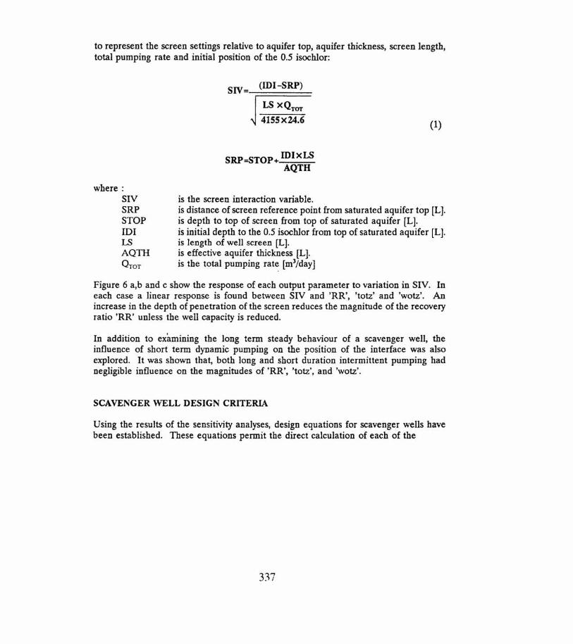
to represent the screen settings relative to aquifer top, aquifer thickness, screen length,total pumping rate and initial position of the 0.5 isochlor:
SIV= (IDI-SRP)
LS XQTOT
4155x24.6 (1)
SRP=STOP+ IDlxLSAQTH
where:SIVSRPSTOPIDILSAQTHQTOT
is the screen interaction variable.is distance of screen reference point from saturated aquifer top [L].is depth to top of screen from top of saturated aquifer [L].is initial depth to the 0.5 isochlor from top of saturated aquifer [L].is length of well screen [L].is effective aquifer thickness [L].is the total pumping rate [mljday]
Figure 6 a,b and c show the response of each output parameter to variation in SlY. Ineach case a linear response is found between SIV and 'RR', 'totz' and 'wotz'. Anincrease in the depth of penetration of the screen reduces the magnitude of the recoveryratio 'RR' unless the well capacity is reduced.
In addition to examining the long term steady behaviour of a scavenger well, theinfluence of short term dynamic pumping on the position of the interface was alsoexplored. It was shown that, both long and short duration intermittent pumping hadnegligible influence on the magnitudes of'RR', 'totz', and 'wotz'.
SCAVENGER WELL DESIGN CRITERIA
Using the results of the sensitivity analyses, design equations for scavenger wells havebeen established. These equations permit the direct calculation of each of the
337

parameters 'RR', 'totz' and 'wotz' and were derived from a full regression analysis of theresults of the sensitivity tests.
a) Empirical Formula for 'RR':
RR [ ]0.093-=-1.869aT + 0.0175IDI + 0.694 KKh.100 mas
0.643 ](IDI-SRP) + (O.00021AQTH-0.03)AQTH
JQmrXLS
...... (2)
where:aTmas : transverse dispersivity in the direction of maximum permeability [L].KJK. : permeability anisotropy ratio.~ : horizontal permeability [Lff]K. : vertical permeability [IJf].
b) Empirical Formula for 'totz':
[ ]
0.053
totz = -51.7 aTmu + 0.91IDI + 34.24 ~
-[0.041 + 118.17 ] (IDI -SRP) + (O.0118AQTH -1.294)AQTH
JQTcn:XLS....(3)
c) Empirical Formula for 'wotz'
wotz=71.S98,,_. (0.339-0.0065101)101 - 2.47S[ ~ f'"(O.0174QTcn:XLS + 0.781(IDI-SRP»)
+ -~
JQTcn:XLS
The selection of the design parameters values, STOP, LS and QTOT' depends on thephysical properties of the aquifer system and on the required value of'RR'. Equation(2) defines the recovery ratio 'RR' as a non linear function of aquifer properties andwell screen settings. In order to illustrate the influence of the primary design
338

parameters on the recovery ratio, an example based on the aquifer conditions found atPSW4C is presented in Table 1. In this table the parameters, aTmaxo Kt.1K. and AQ11Iobserved at the site are shown. Using equation (2) 'RR' is calculated for a range ofQTOTo LS and STOP. From this table it can be seen that for an optimal value of'RR'for STOP=8 of 76%, LS must be 12 m and QTOT 2025 m3/day.
Clearly, it is not possible to change the aquifer characteristics in order to derive anoptimal recovery ratio for a particular site, but different sites will have differentcharacteristics. To illustrate the influence of the physical conditions on recovery, Table2 is presented. In Table 2 the parameters, KblK. and STOP, are kept constant andvalues of 'RR' are calculated for a range of values of QTOT' LS, aTmaxo IDI and AQ11I.
Each of the equations presented in this paper can be used in conjunction with standardwell design criteria and cost functions, as well as cost functions for the disposal of thesaline water to develop a full economic scavenger well design.
SUMMARY AND CONCLUSIONS
Recovery of thin fresh groundwater lenses overlying saline water is important in manyparts of the world. A prime example is the Lower Indus irrigation area in Pakistan.Scavenger wells have been proposed as the most cost effective and practical methodsof recovering the fresh water derived from seepage from canals in the Sind region ofPakistan. Four test sites have been used to establish the viability of the scavenger wellsystems under field conditions. Using the data obtained from one of these test sites, asimulation study has been undertaken to gain a better understanding of the movementof the fresh/saline water transition zone around a scavenger well and its influence onthe design of scavenger well systems. A model was developed to simulate the movementof saline and fresh water under constant and variable pumping conditions. The modelwas calibrated using the available field data. The model was then subsequently used tocarry out an extensive sensitivity analysis to determine the influence of each of thephysical and major well design variables influencing the recovery of fresh water from the·aquifer.
The sensitivity analysis has been achieved by analysing the behaviour of the parameters:recovery ratio, 'RR', rate of upconing, 'rou', depth to top of transition zone, 'totz' andthe thickness of the transition zone 'wotz' under different physical, hydrogeological andoperational conditions.
The results of the sensitivity analysis were used to identify the parameters which stronglyaffect the values of 'RR', 'totz' and 'wotz'.
Based on the results of the sensitivity analysis empirical formulae for 'RR', 'totz' and'wotz' have been established. These formulae can be used to assist in the optimal designof scavenger wells.
The results of the study further confirm the potential for using scavenger wells to exploitshallow fresh water lenses in otherwise saline aquifers.
33y

REFERENCESAliewi, AS. (1993). Numerical Simulation of the Behaviour of the Fresh/Saline WaterTransition Zone Around a Scavenger Well. A PhD thesis, University of Newcastle uponTyne, United Kingdom, 250pp.
Beeson, S., Carruthers R. and Wyness A J. (1992). Scavenger Wells: 2 - Fieldinvestigations and monitoring, in Study and Modelling of Salt Water Intrusion intoAquifers, Proceedings of the 12th Salt Water Intrusion Meeting, 1-6, November, 1992,Barcelona, Spain.
Birch, R.P. and Van Wonderen, J. (1990). Exploitation of freshwater lenses in SindProvince, Pakistan. Intn. Comm. Irrig. Drainage 14th Congress - Rio de Janeiro, Q42-R30, 445-460.
Bruins, H.J., Tuinbof, A and Keller, R. (1991). Water in the Gaza Strip. Hydrologystudy by the Ministry of Foreign Affairs of the government of the Netherlands. Finalreport.
Fader, s.w. (1957). An analysis of contour maps of 1955 water levels with a discussionof salt-water problems in southwestern Louisiana. Wat. Resour. Pamp., (4), 16-27.Published by the Department of Conservation, Louisiana Geological Survey andLouisiana Department of Public Works, Baton Rouge, USA
GDC and BGS (1988). Scavenger wells and pilot studies: Surface geophysics. Reportto UK Overseas Development Administration, London.
GDC and BGS (1989a). Scavenger wells and pilot studies: Hydrogeology. Report to UKOverseas Development Administration, London.
GDC and BGS (1989b). Scavenger wells and pilot studies: Computer model studies.Report to UK Overseas Development Administration, London.
GDC and BGS (1989c). Scavenger wells and pilot studies: Pumping plant study. Reportto UK Overseas Development Administration, London.
GDC and BGS (1989d). Scavenger wells and pilot studies: Scavenger well operationand maintenance. Report to UK Overseas Development Administration, London.
GDC and BGS (198ge). Scavenger wells and pilot studies: Monitoring (1989). Reportto UK Overseas Development Administration, London.
GDC and BGS (1990). Scavenger wells and pilot studies: Summary. Report to UKOverseas Development Administration, London.
HTS and MMP (1965). Lower Indus Report, WAPDA, Lahore.
340

Long, R.A (1965). Feasibility of a scavenger-well system as a solution to the problemof vertical salt-water encroachment. State of Louisiana Department of Conservation,Geological Survey and Department of Public Works in Cooperation with USGS Wat.Resour. Pamp. No. 15.
McWhorter, D.B. (1972). Steady and unsteady flow of fresh water in saline aquifers.Wat. Management Technical Report No. 20, Colorado State University, Fort Collins,Colorado, USA, 49 pp.
Pennink, J.M.K. (1904). The water-supply system of Amsterdam in the dunes. KoninskiInst. Ing. Tidjschr. 1903-1904, The Hague, 183-238.
Pennink, J.M.K. (1905). Investigations for ground-water supplies. Trans. Amer. Soc.Civ. Engrs., Intnl. Engrg. Congress, 54, Section D, Paper No. 50, 169-181.
Reilly, T.E., Frimpter, M.H., LeBlanc, D.R and Goodman, AS. (1987). Analysis ofsteady-state saltwater upconing with application at Truro Well Field, Cape Cod,Massachusetts. Ground Water, 25(2).
Shearer, T. R and Van Wonderen J. (1992). Scavenger Wells:4 - Simulation Modelling.in Study and Modelling of Salt Water Intrusion into Aquifers, Proceedings of the 12thSalt Water Intrusion Meeting, 1-6, November, 1992, Barcelona, Spain. •
Stoner, RF. and Bakiewicz, W. (1992). Scavenger wells 1- Historical development. inStudy and Modelling of Salt Water Intrusion into Aquifers, Proc. 12th Salt WaterIntrusion Meeting (SWIM), Barcelona, Spain.
Van Wonderen J. and Jones C. R. C. (1992). Scavenger Wells: 5 - Design Criteria andimplementation in Sindh. in Study and Modelling of Salt Water Intrusion into Aquifers,Proceedings of the 12th Salt Water Intrusion Meeting, 1-6, November, 1992, Barcelona,Spain.
Zack, A (1988). A well system to recover water from a freshwater-saltwater aquifer inPuerto Rico. USGS. Water Supply No. 2328
341

Table 1: Simulationof 'RR' forStandardAquiferPropertiesand differentvaluesof STOP
Q'Tmax= 0.02,KhlKv = 20 ,AQTH = 55QTOT LS RR
STOP=O STOP=8 STOP=15675 4 61 59 571350 8 81 74 682025 12 84 76 682700 16 84 75 673380 20 82 73 644050 24 80 70 614730 28 77 67 585405 32 74 63 546080 36 70 60 516755 40 67 56 47
Table 2: Simulation of 'RR' for Low and High Levels of Q'Tmax' IDI and AQTH
KhlKv = 20 ,STOP = 0QTOT LS Q'Tmax 101 AQTH
0.01 0.05 33 43 45 55675 4 63 55 51 71 70 561350 8 82 75 68 93 88 762025 12 86 78 71 97 91 812700 16 86 78 71 97 90 813380 20 84 77 70 95 88 804050 24 82 74 68 92 84 784730 28 79 71 65 89 80 765405 32 76 68 62 85 76 736080 36 72 65 59 81 72 71
6755 40 69 61 56 77 68 68
342

FIGURE 1 : SCAVENGER \';£LL CO:-<FIGURATIONSA) SINGLE \~ELLB) TWINNED WELLS
TO YH"f.l! SlJPPLY GIlOONllSJiF!eE
l YAm UBIl WRIlt f'(I(PIlt
FRESH'i1rn tBaSITION ZOIIE OORIJ«i PIl!PIlt
~~-
A
TO 'I1TEl! ~PLY TO DISPOSAL GIlOO1iIJ S1lYJ!CE
I~lmL~"
8ruXSITIOW ZL\'E !mIlt !WIlt
343

GURE 2: LOCATION ~~P OF PROJECT AREA After GDC & BGS (Volume 1,1990)
CHlru\
N :,r.CiiAr-HSTANI 1s,1.:Jm:lb."\o1
•/
I •/CveU3
; ./
RohrlCanal
\ ,- ". Karachi
~C?-.300 Mile \. ,/
I
I
\
NAWABSHAH "-DISTRICT
KEYProject BoundaryRoadCanalBranchTown or VillagePSWSitePSW AbandonedSites
Scaleo 2 G 0 10 Miler;;;;;;;.••••• ~
344

FIGURE 3: SENSITIVITY OF THE TRANSITION ZONETO TRANSVERSE DISPERSIVITY
A) O.2m
o 10 20 30 ..a eo 60 70 eoDISTANCe: (m) FROM SCAVENCER WEll
B) O.02m
o 10 20 30 4{) 50 60 70 60!XST ANC:£ (m) f'ROI,/ SCA VO«;ER WELl..
-10:
-20
--o 10 20 :'0 .0 50 GO 70 e'o
DOS rANCC (m) FROM SCAVENGER WELL
345
IX! 100
110 100
lO
90 100

FIGURE 4: SENSlTIViTY Ui' Hit; TKlU'l::>111Vl' L.Vl'r.
TO THE INITIAL POSITION OF 0.5 ISOCHLOR
§ o.o~O.I~
~~~&-= to~.s
10 :W 30 ~ 50 80 70 60 90 100DISTANCE (m) FRaoI seA\/ENGER waL
B) 41 m bz L-10:
-20:~.s 0.1
.0---. .
~-40==..5-- -o:t:-?-O- -to::0.9 -a
~~o:
0 10 20 30 ~ 50 80 70 60 90 100DISTANCE (m) FRaoI seA \/ENGER waL
C) 36 m bgl-10::
-20:~".§.
~~--50
~O0
1-----0.0--.....
Cl.50.1
10 20 30 ~ 50 80 70 60 90 100CCSTANCE (m) FRaoI seA\/ENGER waL
-1> . - - -o
0:r.
~Ao
o-
0:
D) 0.0 Isochlor for A. Band C
-2
-5
-eo 10 w ~ ~ 50 ~ ro ~ 90 '00
osr ANCE (m) FROM SCA V"<.NGEJl WRL
346

FIGURE 5: SENSITIVITY OF THE TRANSITION ZONETO PERMEABILITY .ANISOTROPY RATIO
A Kh v - t
o 10 20 30 ~o 50 60 70 60OCSTANa: (m) FROM SCA VENOER WEll.
100
-10B Kh Kv - 10
10 20 .30 4.0 50 0,0 70 80OCSTI-Na; (m) FROM SCA~ WEll.
100
C) I<h/Kv •• :lO-10
-20
'R..x;-5.
§~"-:,c;
410
0
o~-~---------- O~ ~io -~_ ~_
---to Q..5-10-"':":'--\
::0., ,.,1 ii'" i ,, ••• I" i' j i 1"1 i •• ii'" 'I
~O 40 50 00 70 80 00 100O<5TANa; (m) mOM SCAVENOER .•••"ELL

FIGURE 6: SENSITIVITY TO SIV
a:::a:::
.i->:
.
FIGURE 60: RR VERSUS SIV
1 2SIV
FIGURE 6b: totz VERSUS SIV6
6e: wotz VERSUS SIV
10SIV
348