experiments on seismic retrofit and repair … in seismic... · experiments on seismic retrofit and...
TRANSCRIPT
Page 1 of 8
EXPERIMENTS ON SEISMIC RETROFIT AND REPAIR OF
REINFORCED CONCRETE SHEAR WALLS
Hamed LAYSSI
PhD Candidate
Department of Civil Engineering and Applied Mechanics, McGill University
817 Sherbrooke St. W., Montréal QC, Canada H3A 2K6
Denis MITCHELL
Professor
Department of Civil Engineering and Applied Mechanics, McGill University
817 Sherbrooke St. W., Montréal QC, Canada H3A 2K6
Abstract
The reversed cyclic loading responses of full-scale shear wall specimens were investigated.
The walls were designed and detailed to simulate non-ductile reinforced concrete construction
of the 1960’s, having lap splices of the longitudinal reinforcement in the potential plastic
hinge region, and having inadequate confinement of the boundary regions. The walls were
tested under reversed cyclic loading with loading applied near the tip of the walls. The
response of the original walls was associated with the brittle failure of the lap splice. The
effectiveness of a retrofit technique and a repair technique were investigated. The retrofit
involved the use of carbon fibre-reinforced polymer (CFRP) wrap for improving the lap splice
behaviour and the shear strength of the walls. The repair of the previously tested specimens
using a steel fibre-reinforced self consolidating concrete (SFRSCC) jacket, and CFRP wrap
was investigated. The retrofit and repair techniques improved the displacement ductility, and
prevented premature failure of the lap splices.
Keywords: Carbon Fibre Reinforced Polymers, Lap splice, Reversed cyclic loading, Repair, Seismic Retrofit, Shear Walls
1. Introduction
Performance-based retrofit and repair of older RC structures can lead to a cost effective
approach where demolishing and reconstruction is not applicable or economical. There are a
large number of existing RC structures designed according to pre 1970’s standards (i.e.,
gravity load design, with no specific seismic provisions), which are vulnerable to seismic
hazards [1].
There has been a tendency among researchers and engineers, over the past two decades, to
provide reliable tools in seismic evaluation of such construction, as well as developing cost
effective practical repair and retrofit solutions to upgrade existing substandard designs [2-4].
General deficiencies of such construction have been studied and reported by several
researchers [5, 6], and include short lap splice lengths of the longitudinal reinforcement in
potential plastic hinge regions, insufficient and poorly detailed transverse reinforcement and
inadequate shear strength required to develop hinging [7].
Jacketing is a common technique in seismic retrofit of existing structures and it can improve
Page 2 of 8
strength, stiffness and the confinement of existing elements. Steel, concrete (plain concrete,
fibre-reinforced concrete or reinforced concrete) and fibre reinforced polymers (FRP) jackets
can be used.
Recently, the use of FRP has become more popular in the retrofit and repair of certain RC
structural components, especially for beams, and columns [8, 9]. However, little research is
available on the effectiveness of this technique on the improvement of the seismic response of
the shear walls.
This paper presents the results of reversed cyclic loading responses of poorly designed and
detailed shear walls. The effectiveness of a retrofit and a repair method, with different
performance objectives, was investigated. The retrofit technique involved application of
CFRP wrap for improving the behaviour of deficient lap splices and shear strengthening of
the walls. The repair technique, which was carried out on two failed shear walls, combines
adding a steel fibre-reinforced self-consolidating concrete jacket over the failed lap splice
region, and CFRP wrap for improving confinement and shear strengthening of the rest of the
wall.
2. Experimental Program
Wall specimens were designed and detailed to simulate some general deficiencies of older
shear walls including the critical potential plastic hinging region containing lap splices of the
longitudinal reinforcement and single-leg, improperly anchored transverse reinforcement.
2.1 Design of Test Specimens
Originally, a set of four RC shear walls were designed, and constructed in the laboratory. The
cross sectional dimensions and the amount of concentrated and distributed reinforcement
were chosen to comply with the 1963 ACI [10] design provisions.
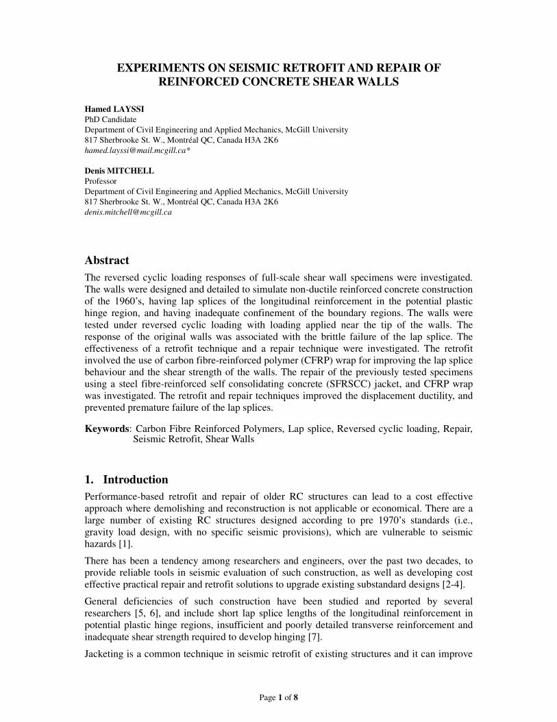
The four walls (two pairs) were identical in every aspect except for amount of concentrated
flexural reinforcement at both ends. The walls had cross-sectional dimensions of 150 mm by
1200 mm. The total height of the walls was 3400 mm. The walls were tested in horizontal
position, cantilevered out from a heavily reinforced foundation block, anchored to the strong
floor. The reversed cyclic loading was applied at a distance of 3250 mm from the base of the
wall by hydraulic jacks (Figs. 1(a) and 1(b)).
Figure 1. (a) Test setup; (b) the details of the as-built wall specimens
Load Cell
Load Cell
PositiveLoadingJacks
NegativeLoadingJacks
3250 mm
Shear wall
Foundation block
Strong floor
2 - 20M
10M @ 277 mm
10M @ 260 mm
10M @ 250 mm
Single leg stirrup
150 mm
120
0 m
m
46 46
85
2 - 20M
150 mm
4 - 20M
4 - 20M
W1 W2(a) (b)

Page 3 of 8
For each pair of identical walls, one wall is tested in as-built condition (W1 and W2), while
the companion wall was retrofitted prior to testing (WRT1 and WRT2). The as-built wall
specimens were repaired after being tested, and were retested in a similar approach (WRP1
and WRP2).
2.1.1 As-Built walls W1 and W2
Walls W1 and W2 were tested in their as-built condition. Two walls are only different in the
amount of concentrated flexural reinforcement at the ends. The flexural reinforcement
consists of 2-20M (single bar area of 300 mm2) for W1 and 4-20M (in two layers) for W2,
located at each end of the walls. Uniformly distributed longitudinal reinforcement consists of
3-10M (single bar area of 100 mm2). The lap splice lengths are about 30 times the bar
diameter (600 mm for 20M bars and 350 mm for 10M bars). The transverse reinforcement
consists of single leg 10M bars with a 90° hook and 6db extension (≈ 60 mm) at each end to
simulate the poor details in existing walls, with the hook oriented vertically without
anchorage around the longitudinal bars at the ends of the thin walls.
It is noted that the lap lengths are considerably shorter than that required by the current ACI
Code [11] and the lap splices are located in a critical region of expected plastic hinging. The
lengths and positions of the lap splices are shown in Fig. 2(a).
2.1.2 Retrofitted Walls WRT1 and WRT2
The retrofit technique involves only the use of carbon fibre wrap, in order to study the effect
of retrofitting with minimal intervention. In this method, the main objective was to prevent
premature failure of the lap splice and to achieve some yielding in the concentrated
reinforcement such that a displacement ductility level of about 2.0 could be reached. Walls
WRT1 and WRT2 had the same structural details as their companions W1 and W2, with the
concrete strengths being slightly higher for retrofitted Walls due to the increase in strength
over time.
.
Figure 2. (a) Detail of as-built wall; (b) retrofit details for WRT1 and WRT2
The entire lap splice length and the potential plastic hinging region was wrapped using uni-
directional CFRP over a length of 180051 =wl. mm. Above this region, the walls were
strengthened in shear by applying carbon fibre wrap strips of 100 mm width, spaced
uniformly at 250 mm, centre-to-centre. The preparation of the concrete surfaces and the
application and carbon fibre wrap was done in accordance with the requirements of ACI
Committee 440 [12]. The carbon wrap was provided with an overlap length of 300 mm on
300
mm
ov
erla
p
Rounded, r = 20 mm
t= 1 mm
300
mm
ov
erla
p
WRT1 WRT2
A
100 mm
1800 mm
A
350 mm
10M lap
splice
Reversed
cyclic
loading
150 mm
600 mm
20M lap
splice
250 mm
CFRP
10M single
leg ties @250 mm
(a) (b)
Fibre
direction
Page 4 of 8
one side of the wall. Fig. 2(b) illustrates the details of the retrofit technique
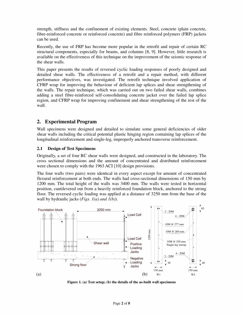
2.1.3 Repaired Walls WRP1 and WRP2
Walls W1 and W2 were repaired after initial test by removing the damaged concrete over the
lap splice region (600 mm). A steel fibre reinforced self consolidating concrete (SFRSCC)
jacket was added over the lap splice zone, increasing the thickness of the wall from 150 mm
to 350 mm. Supplementary flexural reinforcement, anchored properly into the foundation
block, were added to the boundaries and to the web of this new section, prior to casting.
Additional transverse reinforcement was provided in accordance to modern seismic
provisions. A combination of steel threaded rods and surface roughening was used for a better
shear transfer between old and new concrete. Details of the repair technique are shown in Fig.
3.
Figure 3. (a) Details of the repaired walls; (b) cross section of repaired walls WRP1 and WRP2
2.2 Material Properties
The target strength of the concrete used in construction of walls was 30 MPa, a typical
concrete strength for construction in the 1960’s. The steel reinforcement consisted of Grade
400 (minimum specified yield strength of 400 MPa) deformed reinforcing bars.
The carbon fibre wrap and epoxy composite laminate has a design thickness of 1 mm and a
corresponding design strength of 834 MPa in the fibre direction and a breaking strain of
0.85%, according to the supplier’s specifications. The carbon fibre wrap has no strength in the
direction perpendicular to the strips.
The SFRSCC consists of a dry mix SCC concrete (typical 28 days compressive strength of 40
MPa), mixed with 25 mm straight steel fibres. Fibre content was 0.5% of concrete volume.
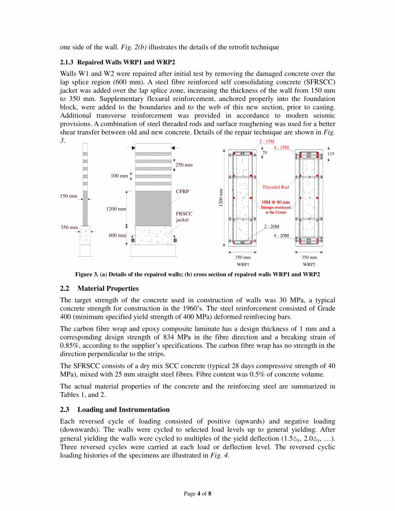
The actual material properties of the concrete and the reinforcing steel are summarized in
Tables 1, and 2.
2.3 Loading and Instrumentation
Each reversed cycle of loading consisted of positive (upwards) and negative loading
(downwards). The walls were cycled to selected load levels up to general yielding. After
general yielding the walls were cycled to multiples of the yield deflection (1.5∆y, 2.0∆y, …).
Three reversed cycles were carried at each load or deflection level. The reversed cyclic
loading histories of the specimens are illustrated in Fig. 4.
4 - 15M
10M @ 80 mmStirrups overlayed
at the Centre
Threaded Rod
10M @ 80 mmStirrups overlayed
at the Centre
2 - 15M
4 - 20M
2 - 20M
350 mm 350 mm
120
0 m
m
WRP1 WRP2
75 115
FRSCC
jacket
100 mm
1200 mm
250 mm
CFRP
600 mmB B
350 mm
150 mm
Page 5 of 8
Table 1. Average concrete material properties.
Wall cf ′ cε ′
rf spf
(MPa) (mm/mm) (MPa) (MPa)
W1 31.2 0.0023 3.79 3.34
W2 30.4 0.0021 4.74 3.50
WRT1 32.4 0.0021 4.06 3.37
WRT2 32.8 0.0021 4.73 4.05
Table 2. Reinforcing Steel Material Properties
Specimen Diameter Area yf yε
uf
(mm) (mm2) (MPa) (mm/mm) (MPa)
10M 11.3 100 470 0.0024 727
15M 16.0 200 426 0.0021 728
20M 19.5 300 460 0.0023 637
0 6 12 18 24 30 36 42 48-320
-240
-160
-80
0
80
160
240
320
Load (
kN
)
Cycle
W1
Load control
0 6 12 18 24 30 36 42 48-320
-240
-160
-80
0
80
160
240
320
Load (
kN
)
Cycle
W2
Load control
0 6 12 18 24 30 36 42 48-320
-240
-160
-80
0
80
160
240
320
Load (
kN
)
Cycle
WRT1
Displacement controlLoad control
Dy
2.0Dy
0 6 12 18 24 30 36 42 48-320
-240
-160
-80
0
80
160
240
320
Load
(kN
)
Cycle
WRT2
Load control Displacement control
Dy2.0D
y
0 6 12 18 24 30 36 42 48-320
-240
-160
-80
0
80
160
240
320
Loa
d (
kN
)
3.5Dy
Dy
Cycle
WRP1
Load control Displacement control
0 6 12 18 24 30 36 42 48-320
-240
-160
-80
0
80
160
240
320
Lo
ad (
kN
)
2.5DyDy
Load control
Cycle
WRP2
Displacement control
Figure 4. Reversed cyclic loading histories
Walls W1 and W2 were tested entirely in load control until failure because flexural yielding
did not occur. Other specimens which experienced flexural yielding, were tested in both load
and deflection control. Testing was stopped at the positive and negative peaks of each cycle to
take photographs and to determine crack widths and the cracking pattern. During loading,
data was collected from the load cells, linear voltage differential transformers (LVDTs), and
strain gages on the reinforcing bars. A potentiometer was used to measure the tip deflection of
Page 6 of 8
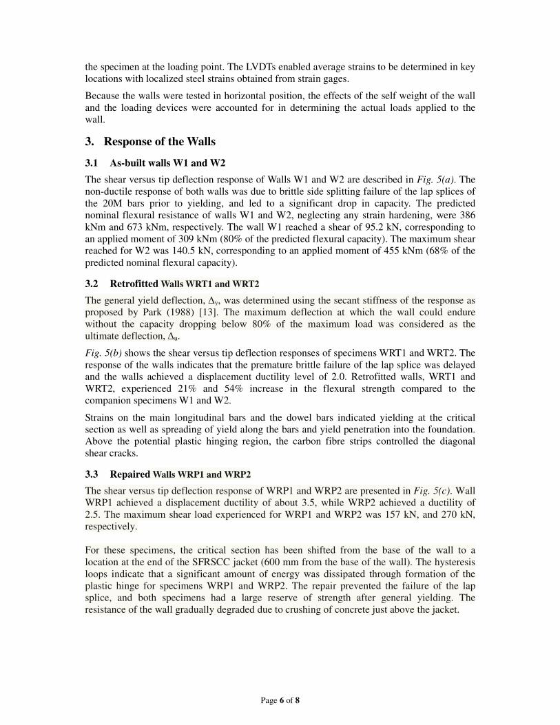
the specimen at the loading point. The LVDTs enabled average strains to be determined in key
locations with localized steel strains obtained from strain gages.
Because the walls were tested in horizontal position, the effects of the self weight of the wall
and the loading devices were accounted for in determining the actual loads applied to the
wall.
3. Response of the Walls
3.1 As-built walls W1 and W2
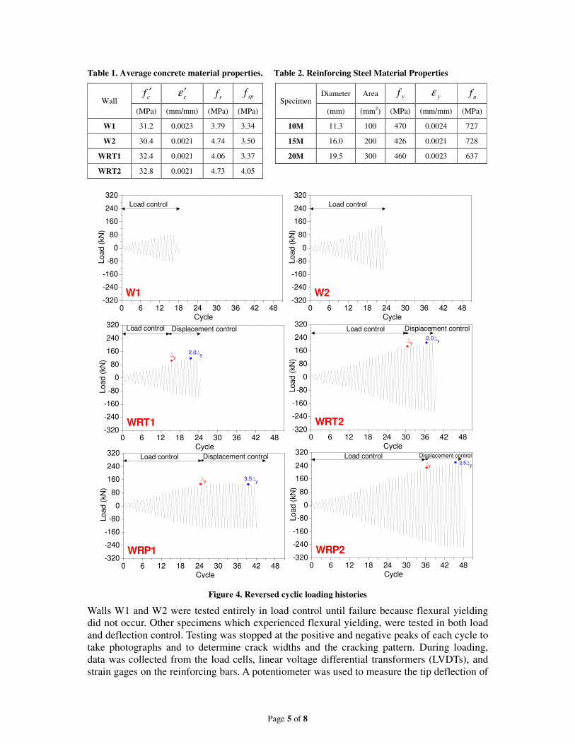
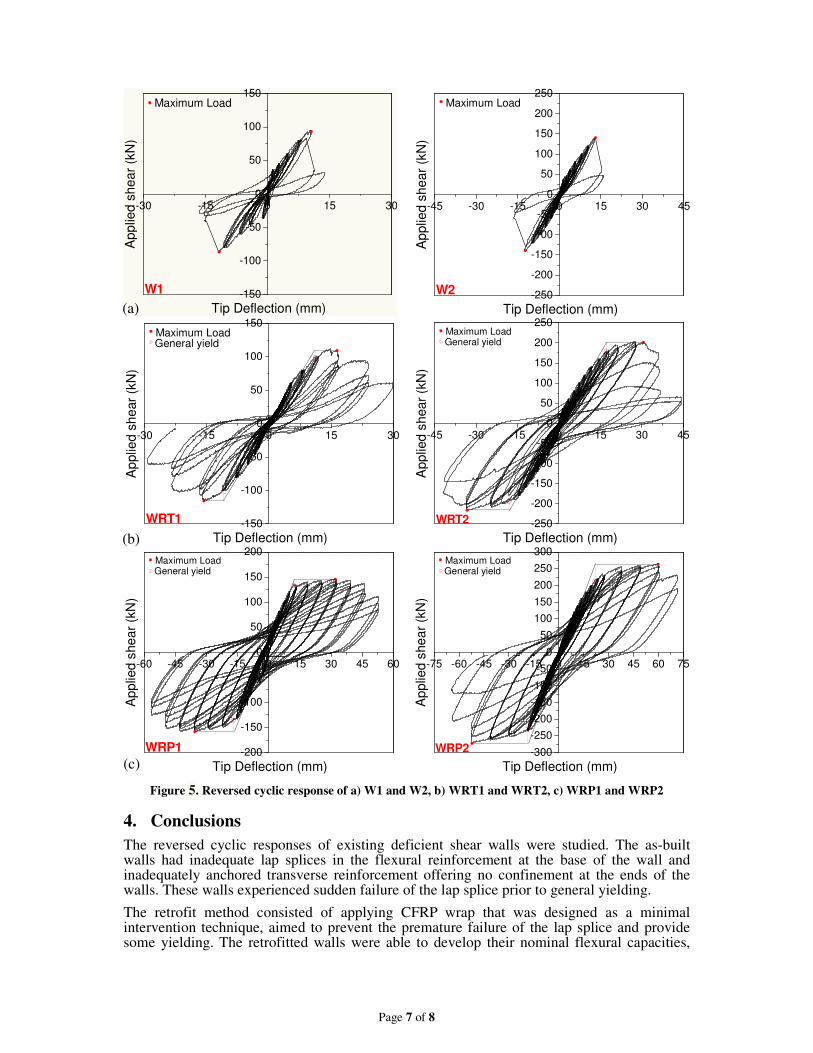
The shear versus tip deflection response of Walls W1 and W2 are described in Fig. 5(a). The
non-ductile response of both walls was due to brittle side splitting failure of the lap splices of
the 20M bars prior to yielding, and led to a significant drop in capacity. The predicted
nominal flexural resistance of walls W1 and W2, neglecting any strain hardening, were 386
kNm and 673 kNm, respectively. The wall W1 reached a shear of 95.2 kN, corresponding to
an applied moment of 309 kNm (80% of the predicted flexural capacity). The maximum shear
reached for W2 was 140.5 kN, corresponding to an applied moment of 455 kNm (68% of the
predicted nominal flexural capacity).
3.2 Retrofitted Walls WRT1 and WRT2
The general yield deflection, ∆y, was determined using the secant stiffness of the response as
proposed by Park (1988) [13]. The maximum deflection at which the wall could endure
without the capacity dropping below 80% of the maximum load was considered as the
ultimate deflection, ∆u.
Fig. 5(b) shows the shear versus tip deflection responses of specimens WRT1 and WRT2. The
response of the walls indicates that the premature brittle failure of the lap splice was delayed
and the walls achieved a displacement ductility level of 2.0. Retrofitted walls, WRT1 and
WRT2, experienced 21% and 54% increase in the flexural strength compared to the
companion specimens W1 and W2.
Strains on the main longitudinal bars and the dowel bars indicated yielding at the critical
section as well as spreading of yield along the bars and yield penetration into the foundation.
Above the potential plastic hinging region, the carbon fibre strips controlled the diagonal
shear cracks.
3.3 Repaired Walls WRP1 and WRP2
The shear versus tip deflection response of WRP1 and WRP2 are presented in Fig. 5(c). Wall
WRP1 achieved a displacement ductility of about 3.5, while WRP2 achieved a ductility of
2.5. The maximum shear load experienced for WRP1 and WRP2 was 157 kN, and 270 kN,
respectively.
For these specimens, the critical section has been shifted from the base of the wall to a
location at the end of the SFRSCC jacket (600 mm from the base of the wall). The hysteresis
loops indicate that a significant amount of energy was dissipated through formation of the
plastic hinge for specimens WRP1 and WRP2. The repair prevented the failure of the lap
splice, and both specimens had a large reserve of strength after general yielding. The
resistance of the wall gradually degraded due to crushing of concrete just above the jacket.
Page 7 of 8
-30 -15 0 15 30
-150
-100
-50
0
50
100
150
Tip Deflection (mm)
Ap
plie
d s
he
ar
(kN
)
Maximum Load
W1
-45 -30 -15 0 15 30 45
-250
-200
-150
-100
-50
0
50
100
150
200
250
W2
Maximum Load
Tip Deflection (mm)
Applie
d s
hear
(kN
)
-30 -15 0 15 30
-150
-100
-50
0
50
100
150
WRT1
Maximum LoadGeneral yield
Tip Deflection (mm)
Ap
plie
d s
he
ar
(kN
)
-45 -30 -15 0 15 30 45
-250
-200
-150
-100
-50
0
50
100
150
200
250
WRT2
General yieldMaximum Load
Tip Deflection (mm)
App
lied
sh
ea
r (k
N)
-60 -45 -30 -15 0 15 30 45 60
-200
-150
-100
-50
0
50
100
150
200
WRP1
General yieldMaximum Load
Tip Deflection (mm)
Ap
plie
d s
he
ar
(kN
)
-75 -60 -45 -30 -15 0 15 30 45 60 75
-300
-250
-200
-150
-100
-50
0
50
100
150
200
250
300
WRP2
General yieldMaximum Load
Tip Deflection (mm)
Ap
plie
d s
he
ar
(kN
)
Figure 5. Reversed cyclic response of a) W1 and W2, b) WRT1 and WRT2, c) WRP1 and WRP2
4. Conclusions
The reversed cyclic responses of existing deficient shear walls were studied. The as-built walls had inadequate lap splices in the flexural reinforcement at the base of the wall and inadequately anchored transverse reinforcement offering no confinement at the ends of the walls. These walls experienced sudden failure of the lap splice prior to general yielding.
The retrofit method consisted of applying CFRP wrap that was designed as a minimal intervention technique, aimed to prevent the premature failure of the lap splice and provide some yielding. The retrofitted walls were able to develop their nominal flexural capacities,
(a)
(b)
(c)
Page 8 of 8
and achieved a ductility of 2.0.
The repair technique consisted of a SFRSCC jacket over the lap splice region, which increased the nominal flexural capacity of the wall at its base. The walls developed significant yielding in the flexural bars and achieved higher displacement ductilities and flexural moment capacities.
This research provides a simple, cost-effective means of retrofitting and repairing deficient RC walls
5. Acknowledgements
The authors gratefully acknowledge the financial support provided by the Canadian Seismic
Research Network (CSRN), funded by the Natural Sciences and Engineering Research
Council of Canada (NSERC).
6. References
[1] GHOBARAH, A. “Seismic assessment of existing RC structures”, Journal of Progress in Structural Engineering and Materials, Vol. 2, No. 1, Jan/March 2000, pp. 60-71.
[2] PRIESTLEY, M. J. N., SEIBLE, F. “Design of seismic retrofit measures for concrete and masonry structures”, Journal of Construction and Building Materials, Vol. 9, No. 6, Month 1995, pp. 365-377.
[3] FIORATO, A.E., Oesterle, R.G., and Corley, W.G. “Behavior of Earthquake Resistant Structural Walls Before and After Repair”, ACI Structural Journal, Vol. 80, No. 5, September 1983, pp. 403-413.
[4] VECCHIO, F.J., Haro de la penta, O.A., Bucci, F., and Palermo, D., “Behavior of Repaired Cyclically Loaded Shearwalls”, ACI Structural Journal, Vol. 99, No. 3, May 2002, pp. 327-334.
[5] Applied Technology Council (ATC) “Seismic evaluation and retrofit of concrete buildings” (ATC-40 Report), Redwood City, CA, November 1996, 612 p.
[6] HARRIES, K.A., RICLES, J.R., PESSIKI, S., and SAUSE, R. “Seismic retrofit of lap-splices in non-ductile square columns using carbon fiber-reinforced jackets” ACI Structural Journal., Vol. 103, No. 6, pp. 874-884.
[7] PATERSON, J., and MITCHELL, D. “Seismic retrofit of shear walls with headed bars and carbon fiber wrap” ASCE Journal of Structural Engineering, Vol. 129, No. 5, May 2003, pp. 606-614.
[8] ELGAWADY, M., ENDESHAW, M., McLean, D., and SACK, R. “Retrofitting of rectangular columns with deficient lap splices” ASCE Journal of Composites for Constrcution, Vol. 14, No. 1, January 2010, pp. 22-35.
[9] Colalillo, M. A., Sheikh, S.A. “Seismic retrofit of shear-critical reinforced concrete beams using CFRP”, Journal of Construction and Building Materials, Available online April 2011, In press
[10] American Concrete Institute (ACI) Committee 318 “Building code requirements for reinforced concrete” ACI 318-63, Detroit, MI., 1963
[11] American Concrete Institute (ACI) Committee 318 “Building code requirements for reinforced concrete” ACI 318-2011, Farmington Hills, MI., 2011
[12] American Concrete Institute (ACI) Committee 440 “Guide for the design and construction of externally bonded FRP systems for strengthening concrete structures”, ACI 440-02, Farmington Hills, MI, 2002, 45 p.
[13] Park, R. “Ductility evaluation from laboratory and analytical testing.” Proc. 9th World Conf. Earthquake Eng. Tokyo-Kyoto, Japan, VIII, 1988, pp. 605–616.