experimental study of wind turbine blade consists of
TRANSCRIPT

Experimental Study of Wind Turbine blade consists of
Airfoils (NACA 63.XXX+FFA-W3) Tarek Abdel Malak Mekhaila, Mohamed Fathy Cideka, Hesham Sayed Abdel-Mohsena and
*Ahmed Salah Mousab
aMech. Eng. Dept., Aswan Faculty of Ene. Engineering, Aswan University, Aswan, Egypt bNew and Renewable Energy Authority
Abstract—Wind turbines have been shown to be one of
the most viable sources of renewable energy. With new
technology, the low cost of wind energy is competitive
with more conventional sources of energy such as coal.
Most blades available for commercial grade wind turbines
incorporate a straight span-wise profile and airfoil shaped
cross sections. In this paper studies of NACA 63.XXX+FFA-
W3 airfoils blade at zafarana wind farm, Egypt. The Wind
turbine’s structure, parameters, electrical control system
and low voltage installation are introduced; there are two
projects at Zafarana site are focused. The first is named as
zafarana No. (7) Consists of 142 turbines as shown figure
(1-a) and the other is named as zafarana No. (8) Consists
of 142 turbines as shown figure. (1-b), the distance
between them is about 12 kilometers. This paper studies
the effect of wind speed, landscape, alarms and spare
parts on the power production and availability
Keywords—: wind turbine, power generation, availability, wind
speed
Fig. 1-a
I. INTRODUCTION
Wind turbines interact with the wind, capturing part of its kinetic energy and converting it into usable energy. Historic designs, typically large, heavy and inefficient, were replaced in the 19th century by fossil fuel engines and the implementation of a nationally distributed power network. A greater understanding of aerodynamics and advances in materials, particularly polymers, has led to the return of wind energy extraction in the latter half of the 20th century. Wind power devices are now used to produce electricity, and commonly termed wind turbines. This paper mainly introduces studying two projects in zafarana site and the affection of climate, landscape, human factors, mitigations loads “depend on national network of electricity “ and spare parts.
Fig. 1-b
Fig. 1-a, 1-b the landscape zafarana NO. (8) is flatter than
zafarana NO.(7)
19
International Journal of Applied Energy Systems, Vol. 2, No. 1, Jan 2020 ISSN: 2636 - 3712 (Printed Version) ISSN: 2636 - 3720 (Online Version) Special Issue: ICEE-2019

II. WINDTURBINE DESCRIPTION
The Gamesa G52- 850 kW is a three bladed, upwind,
pitch regulated and active yaw upwind-turbines as
shown figure 2-a It has a rotor diameter of 52 m as
shown figure 2-b and uses the Ingecon-W control system
concept that enables the wind-turbine to operate in a
broad range of variation of rotor speed [1]. The rotor
pitch is variable and equipped with Optitip system. This
feature provides fine adjustment of the blade-operating
angle at all times with respect to power production and
noise emission.
The main shaft transmits the power to the generator through the gearbox. The gearbox is a 3 stages Combined planetary and helical parallel shafts gearbox. From it the power is transmitted via a flexible coupling to the generator. The generator is a high efficiency 4 – pole doubly fed generator with wound rotor and slip rings. The wind-turbine primary brake is given by full feathering the blades. The redundant brake is an emergency disc brake system hydraulically activated and mounted on the gearbox high-speed shaft. All functions of the wind turbine are monitored and controlled by several microprocessor based control units. The controller system is placed in the nacelle. Blade pitch angle variation is regulated by a hydraulic system actuator which enables the blade to rotate from –5o to 88o. This system also supplies pressure to the brake system. The yaw system consists of two gears electrically operated and controlled by the wind turbine controller based on information received from the wind vane mounted on top of the nacelle. The yaw gears rotate the yaw pinions, which mesh with a large toothed yaw ring mounted on the top of the tower. The yaw bearing is a plain bearing system with built-in friction.
A- INGECON-W SYSTEM
The Ingecon–W system consists of an effective
asynchronous generator with wound rotor, slip rings,
and two 4-quadrant converters with IGBT switches,
contactors and protection [2]
Fig. 2-a B- MEASURING THE WIND
Outside the nacelle, in the rear part, a vertical mast supports the wind-measuring sensors (anemometer and wind-vane).
Vane)
F. 2-b
20
Faculty of Energy Engineering - Aswan University - Aswan - Egypt

C- DESCRIPTION OF THE DOUBLE FED SYSTEM
The double fed machine (DFM) is the equipment that
regulates and protects electrical energy production from
the wind turbine. The double fed machine consists of a
double fed asynchronous generator with access to the rotor
winding via slip rings. The stator (in delta) is connected
directly to the grid and the rotor is connected to a
frequency converter[3]. In addition, the converter is
connected to the grid. This layout ensures that, for
electrical distribution grid, the wind turbine behaves as a
synchronous generator. Which serves to stabilize the grid,
enabling the connection of several wind turbines, and
eliminates the need for capacitor banks to compensate
reactive power and resonance problems, The converter
control unit (CCU) controls the active and reactive power
with the frequency converter connected to the generator
rotor, this is, and it allows the user to select the desired
power factor.
The single row-diagram the double fed machine is as
following
The main characteristics of the LV installation are
listed below.
• Rated voltage 690 V
• Frequency 50/60HZ
• Rated power 850KW
• Rated current a t690V 800 A
• Maximum short- circuit current in LV (MV grid+generator) 16 A
• Rated current provided by a wind turbine at 20KV 27.6 A
• Rated current provided by a wind turbine at 30KV 18.4 A
Generator data • Voltage per phase 690 V
• Resistance of stator“R1” 0.0159(115 C)
• Reactance of stator"X1" 0.0755Ω
• Resistance of the rotor referred to stator "R2"
0.011Ω
• Reactance of the rotor referred to stator "X2"
0.105Ω
Tables 1. Parameters of the design of G52 - 850 KW
wind-turbines [4]
Remarks Units Value Concept
IEC 61400-
Ed.2
- S IEC class
Referred to
hub height
m/s 7.5 Annual mean wind speed
- 2 Weibull shape parameter
,K
% 16 Turbulence intensity at
15m/s,I16
50 years
recurrence
time
m/s 43 Reference wind 10min.
averaged
50 years
recurrence
time
m/s 52.5 Reference wind 3 sec.
averaged
100 sec filtered m/s 21/18 Stop / restart wind speed
21
International Journal of Applied Energy Systems, Vol. 2, No. 1, Jan 2020 ISSN: 2636 - 3712 (Printed Version) ISSN: 2636 - 3720 (Online Version) Special Issue: ICEE-2019
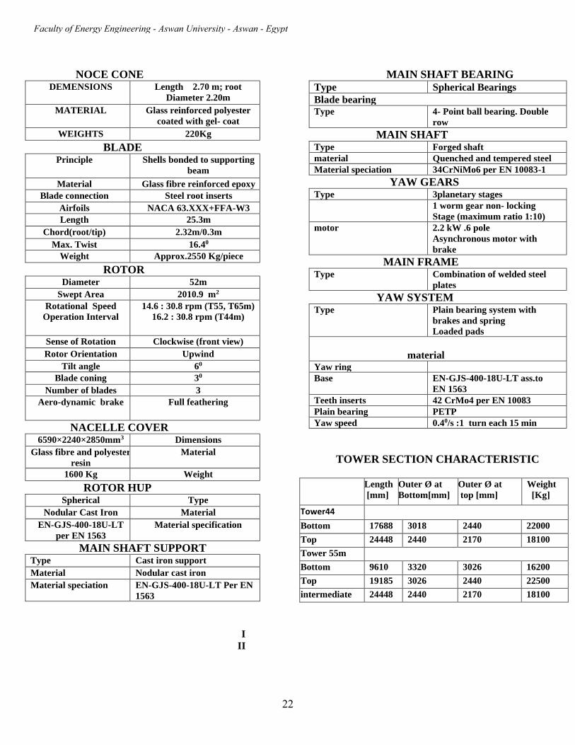
NOCE CONE
DEMENSIONS Length 2.70 m; root
Diameter 2.20m
MATERIAL Glass reinforced polyester
coated with gel- coat
WEIGHTS 220Kg
BLADE
Principle Shells bonded to supporting
beam
Material Glass fibre reinforced epoxy
Blade connection Steel root inserts
Airfoils NACA 63.XXX+FFA-W3
Length 25.3m
Chord(root/tip) 2.32m/0.3m
Max. Twist 16.40
Weight Approx.2550 Kg/piece
ROTOR
Diameter 52m
Swept Area 2010.9 m2
Rotational Speed
Operation Interval
14.6 : 30.8 rpm (T55, T65m)
16.2 : 30.8 rpm (T44m)
Sense of Rotation Clockwise (front view)
Rotor Orientation Upwind
Tilt angle 60
Blade coning 30
Number of blades 3
Aero-dynamic brake Full feathering
NACELLE COVER
6590×2240×2850mm3 Dimensions
Glass fibre and polyester
resin
Material
1600 Kg Weight
ROTOR HUP
Spherical Type
Nodular Cast Iron Material
EN-GJS-400-18U-LT
per EN 1563
Material specification
MAIN SHAFT SUPPORT
Type Cast iron support
Material Nodular cast iron
Material speciation EN-GJS-400-18U-LT Per EN
1563
MAIN SHAFT BEARING
Type Spherical Bearings
Blade bearing Type 4- Point ball bearing. Double
row
MAIN SHAFT Type Forged shaft
material Quenched and tempered steel
Material speciation 34CrNiMo6 per EN 10083-1
YAW GEARS
Type 3planetary stages
1 worm gear non- locking
Stage (maximum ratio 1:10)
motor 2.2 kW .6 pole
Asynchronous motor with
brake
MAIN FRAME
Type Combination of welded steel
plates
YAW SYSTEM
Type Plain bearing system with
brakes and spring
Loaded pads
material Yaw ring
Base EN-GJS-400-18U-LT ass.to
EN 1563
Teeth inserts 42 CrMo4 per EN 10083
Plain bearing PETP
Yaw speed 0.40/s :1 turn each 15 min
TOWER SECTION CHARACTERISTIC
Length
[mm] Outer Ø at
Bottom[mm] Outer Ø at
top [mm]
Weight
[Kg]
Tower44
Bottom 17688 3018 2440 22000
Top 24448 2440 2170 18100
Tower 55m
Bottom 9610 3320 3026 16200
Top 19185 3026 2440 22500
intermediate 24448 2440 2170 18100
I
II
22
Faculty of Energy Engineering - Aswan University - Aswan - Egypt

III .Case study of wind turbine blade consists of
profiles (NACA63.xxx+FFA-W3), model G52
Table 2. Comparison between two project at Zafarana
wind farm, Egypt through years 2017, 2018, 2019 name Zafarana No.(8) Zafarana No.(7)
No. of turbines 142 142
Turbine model G52 G52
Rated power(per a
turbine)
850 KW 850 KW
Manufacturer Gamesa Gamesa
Total power 120 MW 120 MW
Blade airfoils NACA
63.XXX+FFA-
W3
NACA
63.XXX+FFA-
W3
The affection of the wind and landscape on power
production and availability through years 2017, 2018,
2019 as shown at the following figures and tables.
Some notes:- A- The distance between the two projects is about 12
kilometers
B- The landscape of project Zafarana No.(7) is worse than
the landscape of project Zafarana No.(8) as shown
figure(1-a), (1-b)
IV .RESULTS AND DISCUSSION
Figures[3,4,5] show power generation distribution of
project Zafarana NO.(8) and project Zafarana No.(7)
through years 2017, 2018, 2019 respectively where
year 2019 is from (Jan to Sep), and show the effect of
wind speed, landscape and availability on the power
generated from the two projects. as shown the power
increases with the wind speed
Generally, the power generated from Zafarana No. (8)
is larger than from Zafarana No. (7) Because of :
1- The wind speed in Zafarana No. (8) Is higher than in
Zafarana No. (7)
2- The landscape of Zafarana No. (8) Is flatter than
Zafarana No. (7)
3- Efficient manpower plays main role in the power
generation
Figures [6], [7] show the power distribution of the two
projects in June and December. At Year 2017 the
maximum power was occurred in June and the
minimum power was occurred in December at the two
projects.
Figures [8,9] show the power distribution of the two
projects in September and November.
At Year 2018 the maximum power was occurred in
September and minimum power was occurred in
November at the two projects.
As the years pass, the wind speed decreases gradually
where the average wind speed at 2019 was smaller than
at 2018, and the average wind speed at 2018 was
smaller than at 2017 in zafarana site.
Table 3. annual power distribution of the two projects in 2017
months Zafarana NO.(8) Zafarana NO.(7)
Power(MWh) Wind(m/s) availability Power(MWh)) Wind(m/s) availability
Jan 19407 6.7 89.8% 18846 5.8 73.4%
Feb 19042 5.6 93.3% 16219 6 76.1%
mar 21190 6.8 93% 17161 6.1 74.8%
apr 21784 6.9 84% 20956 6.2 73.6%
may 17022 6.8 76.9% 15789 6.5 76.6%
Jun 25995 7.4 68.1% 20882 6.4 57.3%
jul 21212 7.3 68% 17714 6.6 60.1%
Aug 21399 7.5 67.6% 16517 6.5 63.5%
sep 16799 8.5 64.7% 18186 8.2 55.1%
oct 17615 7.2 73% 13325 6.5 55.6%
nov 15303 4.9 81.3% 13839 6.1 62.9%
Dec 9790 5.6 81.7% 9499 5.5 66.4%
23
International Journal of Applied Energy Systems, Vol. 2, No. 1, Jan 2020 ISSN: 2636 - 3712 (Printed Version) ISSN: 2636 - 3720 (Online Version) Special Issue: ICEE-2019

Fig. 3 Annual power distribution of the two projects in 2017
Fig. 6 Power distribution of the two projects in June (2017)
Fig. 7 Power distribution of the two projects in Dec. (2017)
89.8%93.3%
93%84%
76.9%
68.1%68%
67.6%
64.7%73% 81.3%
81.7%
73.4%76.1% 74.8%
73.6%
76.6%
57.3%
60.1%63.5%
55.1%
55.6% 62.9%
64.4%
0
5000
10000
15000
20000
25000
30000
jan feb mar apr may jun jul aug sep oct nov dec
Po
wer
(M
Wh
)
month
Annual power production curve (2017)
ZafaranaZ8(MWh) zafarana Z7(MWh)
0
200
400
600
800
1000
1200
1400
1600
0 5 10 15 20 25 30
po
wer
(MW
h)
days (june)
Zafarana (8) MWh Zafarana (7) MWh
0
200
400
600
800
1000
1200
0 5 10 15 20 25 30
Po
wer
(M
Wh
)
Dec. (Days)Zafarana (8) MWh Zafarana (7) MWh
24
Faculty of Energy Engineering - Aswan University - Aswan - Egypt
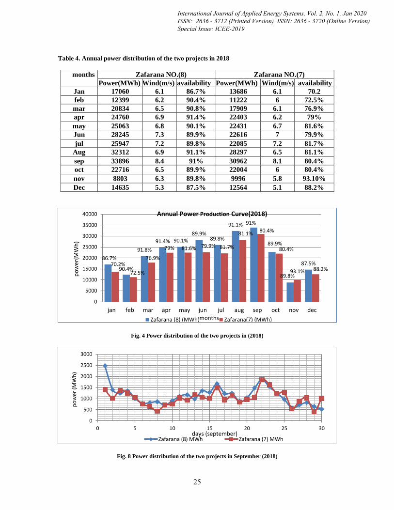
Table 4. Annual power distribution of the two projects in 2018
months Zafarana NO.(8) Zafarana NO.(7)
Power(MWh) Wind(m/s) availability Power(MWh) Wind(m/s) availability
Jan 17060 6.1 86.7% 13686 6.1 70.2
feb 12399 6.2 90.4% 11222 6 72.5%
mar 20834 6.5 90.8% 17909 6.1 76.9%
apr 24760 6.9 91.4% 22403 6.2 79%
may 25063 6.8 90.1% 22431 6.7 81.6%
Jun 28245 7.3 89.9% 22616 7 79.9%
jul 25947 7.2 89.8% 22085 7.2 81.7%
Aug 32312 6.9 91.1% 28297 6.5 81.1%
sep 33896 8.4 91% 30962 8.1 80.4%
oct 22716 6.5 89.9% 22004 6 80.4%
nov 8803 6.3 89.8% 9996 5.8 93.10%
Dec 14635 5.3 87.5% 12564 5.1 88.2%
Fig. 4 Power distribution of the two projects in (2018)
Fig. 8 Power distribution of the two projects in September (2018)
86.7%
90.4%
91.8%
91.4% 90.1%89.9%
89.8%
91.1% 91%
89.9%
89.8%
87.5%70.2%
72.5%
76.9%
79% 81.6% 79.9% 81.7%
81.1%80.4%
80.4%
93.1% 88.2%
0
5000
10000
15000
20000
25000
30000
35000
40000
jan feb mar apr may jun jul aug sep oct nov dec
po
wer
(MW
h)
months
Annual Power Production Curve(2018)
Zafarana (8) (MWh) Zafarana(7) (MWh)
0
500
1000
1500
2000
2500
3000
0 5 10 15 20 25 30
po
wer
(M
Wh
)
days (september)Zafarana (8) MWh Zafarana (7) MWh
25
International Journal of Applied Energy Systems, Vol. 2, No. 1, Jan 2020 ISSN: 2636 - 3712 (Printed Version) ISSN: 2636 - 3720 (Online Version) Special Issue: ICEE-2019

Fig. 9 Power distribution of the two projects in November (2018)
Table 5. Power distributions of the two projects in 2019
months Zafarana(Z8) (MWh)
zafarana(Z7) (MWh)
availability (Z7) %
Availability. (Z8) %
Aver. Wind speed (m/s)
Aver. Wind speed (m/s)
jan 13840 15895 86.30 84.30 6.05 5.8
feb 12477 12608 90.1 89.50 5.7 6
mar 22408 17204 87.3 92.10 6.8 6.2
apr 19507 15176 88.60 91.70 6.64 6.4
may 27826 24142 90.0 90.27 7.3 7
jun 28511 24980 90.80 93.30 8.4 8.7
jul 26983 24608 89.80 89.70 8.57 8.67
aug 23137 21367 91.20 93.40 7.41 8.2
Fig. 5 Power distribution in 2019
-200
0
200
400
600
800
1000
1200
0 5 10 15 20 25 30
po
wer
(M
Wh
)
days(november)Zafarana (8) MWh Zafarana (7) MWh
84.3%89.5%
92.1%91.7%
90.27% 93.3%89.7%
93.4%
86.3%90.1%
87.3%88.6%
90% 90.8% 89.8%
91.2%
0
5000
10000
15000
20000
25000
30000
jan feb mar apr may jun jul aug
po
we
r(M
Wh
)
months
power curve2019
Zafarana(Z8)(MWh) zafarana( Z7)(MWh)
26
Faculty of Energy Engineering - Aswan University - Aswan - Egypt

VI. Conclusions Based on the data obtained from SCADA Systems at
Egypt, Zafarana Wind farm, it turns out the effect of
the following conditions on the power
A-the climate (wind speed, landscape)
B-the human factor
C-Spare parts availability
ACKNOWLEDGMENT This work is funded by the New and Renewable Energy Authority, Egypt
REFERENCES
[1]- Boyle, G. (2004). Renewable energy. Renewable Energy, by Edited by Godfrey Boyle, pp. 456. Oxford University Press, May 2004. ISBN-10: 0199261784. ISBN-13: 9780199261789, 456. [2]- Hudson, R. M. (2008). Control system for doubly fed induction generator: Google Patents. [3]- Ragheb, M. (2012). Wind shear, roughness classes and turbine energy production. Stavrakakis, G. (2012). 2.10 Electrical Parts of Wind Turbines.
27
International Journal of Applied Energy Systems, Vol. 2, No. 1, Jan 2020 ISSN: 2636 - 3712 (Printed Version) ISSN: 2636 - 3720 (Online Version) Special Issue: ICEE-2019