experimental study of wave-driven impact of sea ice floes
TRANSCRIPT

1
Experimental Study of Wave-Driven Impact of Sea Ice Floes on a 1
Circular Cylinder 2
3
David J. McGovern, Wei Bai* 4
Department of Civil and Environmental Engineering, National University of Singapore, Kent Ridge, Singapore 117576, Singapore 5
6
7
Abstract 8
The impact of isolated sea ice floes with offshore structures is a significant environmental hazard for Arctic offshore operations. 9
Most attention to date has focused on the impact of glacial icebergs, and very large drifting ice floes with offshore structures. There 10
appears to be a lack of data in the case of isolated, wave-forced floe-structure interactions. To address this an experimental 11
investigation was conducted to identify impact characteristics of floes of various shapes and sizes with a single circular cylinder. A 12
wide selection of regular and irregular wave conditions were examined and the floe kinematics and impact characteristics 13
determined. In regular waves, the results showed floe kinematic heave and surge responses was unaffected by the presence of the 14
structure at distances of x/D ~ ≥ 10. At x/D ≤ 10 a slight increase in heave response was observed. In the same region, surge was 15
markedly reduced regardless of whether there was an eventual impact. Drift velocity appeared to be the main control on whether 16
the floe would impact (if drift velocity was high enough) or become trapped in the lee of the cylinder and be deflected to one side 17
before impact. 3D analysis of impacts showed that two broad types of impact occurred; a relatively head-on impact and a more side-18
on impact. Head-on impacts were dominated by linear kinetic energy, while side on and secondary impacts exhibited increased 19
rotational kinetic energy. In irregular waves, the impacts were found to occur at any point in the wave cycle, whereas the impacts in 20
regular waves tended to occur at the point of maximum surge near the crest of the wave. The influence of λ/Lc and H/λ on impact 21
occurrence and characteristics was investigated. While H/λ did not have a significant effect on impact occurrence, it appeared that 22
the lower the λ the greater the chance of impact. The influence of Lc and shape in irregular waves indicated larger Lc and cross-23
sectional area of the floe relative to the cylinder increased impact occurrence. 24
25
Key words: Ice Floe; Kinematics; Structure Impact; Floe Drift; Floe Velocity; Experimental Study 26
* Corresponding author.
E-mail address: [email protected] (W. Bai).
2
1
2
1. Introduction 3
4
Due to the predictions of an ice-free Arctic ocean in the summer months by 2040 or earlier (e.g., Turner and 5
Marshal, 2011, and ACIA, 2004), and the discovery of vast hydrocarbon reserves in the Arctic and surrounding 6
northerly seas (e.g. USGS, 2008), offshore activity and trans-arctic shipping is expected to increase rapidly in the 7
coming decades (DNV, 2010). Seasonal offshore hydrocarbon production activities in such cold regions have to 8
contend with a variety of sea ice interactions. Large floes, much larger than the dominant wavelengths, may drift 9
under the influence of currents, wind and wave forcing into a collision with a structure. This is a common hazard 10
for offshore structures situated in ice infested waters (e.g., Keinonen and Truskov, 2001, Loset, 2001, Timco, 11
2011). The impact of large drifting floes against offshore structures has been well studied to date in terms of force 12
and failure modes in the laboratory (for example, Federking and Timco, 2000, Yamauchi et al., 2001, Bekker et 13
al., 2007 and Dong et al., 2012), in the field (see for example the review by Timco, 2011) and mathematically 14
(Croteau et al., 1984, Bhat, 1988, Morland, 1996 and Nevel, 2001). Additionally, excellent reviews of research 15
on sea ice-structure interactions can be found in Squire et al. (1995) and Squire (2007). Here the floes are large 16
in comparison to the incident wavelength and drift under current, wind and wave forcing. These studies focused 17
on the impact force, failure mode and in some cases the dynamic response of the structure; as a result, the 18
understanding of floe failure and impact forces on structures is significant. 19
Offshore structures of various different designs have been operating successfully in ice infested waters for some 20
time (e.g., Lever et al., 2001, Keinonen and Truskov, 2001 and IMVPA, 2008). However, with the changing 21
climate of the Arctic and surrounding seas, and specifically the observed and predicted reduction in sea ice, a 22
new type of ice floe hazard is now emerging; one of small floe sizes in relation to wavelength (McGovern and 23
Bai, 2014). The increase in area of open water will increase the fetch in the arctic resulting in a more severe wave 24
climate than in the past (e.g. Francis et al, 2011). A combination of more severe waves, ice management and 25
melting will act to break up large floes into smaller ones which have lengths much smaller than the dominant 26
wavelengths and are, therefore, sensitive to wave forcing. This was identified by Sun and Shen (2012) for the 27

3
case of pancake ice. They adopted a discrete element numerical model to determine the load induced by a pancake 1
field around cylindrical structures in waves, as well as the impact force on, and bending moment of the structure. 2
As they mentioned, however, pancake ice is only one of numerous types of smaller floe sizes that may become 3
more dominant in a future arctic. Consider, for example, waves interacting with and breaking up ice sheets in the 4
so called Marginal Ice Zone (MIZ) (e.g. Squire, 1984) as well as larger more isolated floes, into small, relatively 5
uniform polygonal shapes that are much larger than pancakes, but may be much smaller than the wavelength. 6
This occurs due to the flexure that is inherent for large floes, and when the flexural strength is exceeded the floes 7
break up into smaller more stable sizes for any given dominant wavelength. Research into this process in the MIZ 8
is extensive (e.g., Masson and LeBlond, 1989, Meylan and Squire, 1994, 1996, Meylan, 2002, Wang and Meylan, 9
2004, Williams and Squire, 2006, to name but a few). 10
Indeed, floes of all sizes from km’s in length to several meters have been observed regularly to interact with 11
structures (e.g. Timco, 2011). Smaller floes may also be generated by ice management in the vicinity of an 12
offshore structure. Moslet (2008) conducted an experiment whereby the impact force on a cylinder for smaller 13
scale floes (30 m by 10 m) with a small cylindrical structure in the field. However, as this was for drifting motion 14
the motion due to waves was not addressed. As a result, there is a lack of information in guidelines on the speed 15
and motion of small ice floes in waves, and particularly their motion in the vicinity of offshore structures (Allyn 16
et al, 2001). In addition, an impact from a small floe surging on a wave onto a structure will be a much shorter 17
event at a much higher velocity in comparison to a relatively slow moving larger floe which will fail by crushing 18
or splitting and deliver a long force event to the structure. 19
For the case of glacial icebergs in waves, the 1st order kinematics are reasonably well researched; heave, sway, 20
surge and roll motions have been studied in the field from very large (km’s in length) icebergs to small bergy bits 21
(meter in length) by Kristensen et al. (1982), Wadhams et al. (1983), Lever and Diemand (1985), Lever et al. 22
(1991) and others. In the laboratory, Murray et al. (1983), Arunachalam et al. (1987) and Lever et al. (1988) all 23
observed glacial icebergs and bergy bits behaving as fluid particles for certain iceberg size and wave conditions. 24
Issacson and McTaggart (1990) observed iceberg drifts in waves and currents, finding that for iceberg diameters 25
less than half the structure diameter, impacts only occurred for smaller ice bergs in combined waves and current 26
conditions. Lever et al. (1990) conducted an extensive series of tests of an ice berg in irregular waves in order to 27

4
accumulate statistics on the location and velocity of impacts with a moored semi-submersible. The semi was 1
observed to be transparent to the incident waves and did not affect upstream ice berg kinematics. The 1st order 2
motion of the semi at impact was generally found to slightly reduce impact velocity. Through the observation of 3
small rotational impact energy, and no dependency between heave and surge impact velocities, a simplified 4
impact kinetic energy (KE) estimation method was developed by considering only translational impact energies. 5
For sea ice floes, Timco (2011) reviewed and compared data from a variety of field and laboratory campaigns on 6
the impact of large floes with small islands, dynamic and stationary offshore structures and drill ships. He 7
provided an analysis of the kinetic energy of the floe at impact to determine impact force, and was able to include 8
a simple equation to predict impact force from kinetic energy. The above generally focuses on large floes with 9
lengths generally much larger than wave length; here the mechanism of failure is generally crushing at the contact 10
surfaces (e.g., Dong et al., 2012), through which a force is applied to the structure. Such force events can last 11
significant periods of time due to the large momentum and mass of these floes. 12
The kinematics of a small sea-ice floe, which is relatively flat and thin in comparison to glacial icebergs, was 13
given specific treatment by McGovern and Bai (2014) in a series of laboratory tests. These consisted of model 14
tests in a range of wave conditions and floe variables with a view to determine the dependent variables of floe 15
kinematics, and observe any differences from glacial ice motion. The results showed a markedly different heave 16
and surge floe response to that of glacial ice and a dependency on floe thickness, shape and length. Extrapolation 17
of the kinetic energy calculated in the model tests predicted impact energies in the order of 10 MJ at prototype 18
scales. An impact at such energy levels would certainly result in a significant force event between the ice and the 19
structure and knowledge of KE at the point of impact has been shown to be sufficient to calculate the impact 20
force of a collision event (Timco, 2011, for the case of large drifting floes). As such, the next step is the 21
investigation of floe structure impacts. There appears to be, to the best of the authors’ knowledge, no prior 22
research on this specific situation, yet guidelines must now look to include such events. 23
This paper aims to build on the previous study of McGovern and Bai (2014) to investigate the wave induced 24
kinematics of floes in the presence of a single slender cylinder. The main questions that arise include; 1) what 25
are the kinematics of the ice on approach to the structure, and how does the structure affect these, 2) what floe 26
properties and what wave conditions will encourage impacts to occur, 3) what are the kinematics of the impact 27

5
process and 4), what is the KE of the floe at the point of impact. 1
2
2. Experimental method 3
4
The wave flume used in the present study is located at the Hydraulic Engineering Laboratory, National 5
University of Singapore. The flume is 2 m wide and approximately 32 m long with a piston type wave paddle 6
generating waves propagating from right to left as in Figure 1. The absorption beach at the downstream end 7
reduced reflections to < 5% of the incident wave height H which is deemed acceptable. The experimental set-up 8
is essentially identical to that described in McGovern and Bai (2014) and in the following only unique aspects of 9
the current set-up are discussed; the reader is advised to refer to that paper for more details. 10
11
Figure 1. Schematic diagram of the flume layout. 12
13
In this study, both regular and irregular waves are addressed. To simulate irregular waves in a limited-fetch 14
environment a unidirectional JONSWAP spectrum was chosen which takes the form 15
( )4
05
5exp4w
fAS ff f
αγ
= −
, (1) 16
where 17
( )20
2 20
exp2f f
fα
σ
−= −
, (2) 18
0
0
0.07 if 0.09 if
f ff f
σ≤
= >, (3) 19
2 40
1/3
5 for 1 416
SH fA γγ
= < < , (4) 20
where f = frequency, fo = peak frequency, Hs is the significant wave height, γ is the peak enhancement factor. This 21
was set to γ = 2.2 following the average value of 11 spectra from the Beaufort Sea in 60 m water depth, as well 22

6
as 36 spectra from the Hibernia region in 95 m depth (LeBlond et al. 1982). Peak period Tp is defined from the 1
same field data as being related to Hs through: 2
1/24.43p sT H= . (5) 3
As was done by Lever and Sen (1987), Lever et al. (1988) and Lever et al. (1990), the simplified relationship 4
between Hs and Tp given in Eq. (5) is used to allow Sw(f) to be dependent on Hs only. A Hs = 12 m in the prototype 5
was chosen to simulate a representative 10 year Hs for the Hibernia oil field region in the North West Atlantic 6
(Neu, 1982) as this was felt plausible for a future ice-free Arctic. This gave a Tp of 15 seconds according to Eq. 7
(5), leading to wave steepness H/λ ≈ 0.033 (where λ is the wavelength) as representative of the field data in 8
LeBlond et al. (1982). λ was determined from the dispersion equation of linear wave theory. Water depth was set 9
to 90 m (0.9 m in the model) and as the wavemaker is single element only long-crested waves were produced. 10
By using a different initial sequence for each run the cycle of irregular waves generated for each run was unique. 11
The regular and irregular wave test conditions are given in Table 1. 12
13
Table 1. Test conditions. 14
15
Table 2 shows the actual Tp and Hs values obtained from the spectral analysis of the irregular wave time series 16
generated by the wavemaker. Actual Tp showed good agreement with the target while Hs was approximately 1 17
cm lower than the target Hs in all cases. 18
19
Table 2. Target and actual irregular wave Tp and Hs. 20
21
The structure consisted of a circular slender cylinder of diameter D = 0.05 m that extended to a depth of 0.8 m 22
to ensure the correct flow field was generated. We employed the Froude (Fr = V/√gL, where V = velocity, g = 23
acceleration due to gravity and Lc = characteristic length) scaling criteria as this is the most appropriate scaling 24
for free surface effects where gravity is the main restoring force. Dissimilitude in Reynolds number R = VD/v, 25
(where the kinematic viscosity of water at 20 degrees Celsius v = 1.004 x 10⁻⁷ cm2/s), will be discussed further 26
in Section 2.1. The Fr relationships between model (m) and prototype (p) are given as: 27

7
𝐿𝐿𝑝𝑝 = 𝑙𝑙𝐿𝐿𝑚𝑚,𝑉𝑉𝑝𝑝 = 𝑉𝑉𝑚𝑚√𝑙𝑙,𝑇𝑇𝑝𝑝 = 𝑇𝑇𝑚𝑚√𝑙𝑙, (6) 1
where l = scale factor which was set at 1:100, L = length and T = time (period). 2
The floe models were constructed from High Density Polyethylene (HDPE) of density ρ = 0.93 kg m-3 and a 3
Youngs Modulus of 1.37 GPa (Gigapascals). The measured density of sea ice from the reported values in Timco 4
and Frederking (1996) varies over a wide range from 0.72 – 0.94 kg m-3 and is dependent on brine content, age, 5
(e.g., first or multiyear) and heterogeneity of the ice. Youngs Modulus of sea ice has been found to range between 6
1-9 GPa (Timco and O’Brien, 1994). Field measurements of individual floe thickness b are between 2 and 6 m 7
for first and multiyear floes respectively (for example, Shirasawa et al. 2009, Kwok and Rothrock 2009 and Xie 8
et al. 2011). Here we focus on a relatively higher density floe of a multiyear thickness as this is hypothesised to 9
result in larger impact force than a thinner and less dense floe, such as a briny first year floe. 10
Time series of the full 6-degree-of-freedom of motion of the floe models was measured using a PhaseSpace 11
Improv motion tracking camera system. The cameras tracked ‘Stylus’ LEDs that measured 5 cm long by 2 cm 12
wide by 0.8 cm thick and weigh 13 grams positioned on plastic stands (8.5 grams) at equidistant points from each 13
corner of the ice model. The total weight of the four LEDs was 84 grams and this was considered during 14
calculations of total model mass, density and kinetic energy. Though the present experiment has a slightly 15
different camera positioning around the flume in order to accommodate the cylinder downstream, the set-up and 16
calibration is the same as described in McGovern and Bai (2014), which also includes detailed discussion of 17
laboratory effects, wave reflection and analysis of current circulation caused by stokes drift within the flume, all 18
of which were found to be negligible for the current set-up. 19
Four different floe shapes were tested (Table 3). 20
21
Table 3. Floe model geometry, mass and density. 22
23
For each run the floe model was positioned 2.5 m upstream of the cylinder as close as possible to the centre of 24
the flume and parallel with the flume walls, i.e., with the centreline dissecting the floe symmetrically (Figure 1). 25
Confirmation of the floe starting position was made from the real-time position data recorded by the Improv 26
cameras. Once the waves started, the Improv system recorded the floes progress towards the cylinder and the 27

8
tests were halted when the floe passed the cylinder completely. In some cases the floe would impact one or more 1
times before passing the cylinder while in others it would pass the cylinder without impact. Each test lasted 2
around 2 minutes on average. Before the next run the flume was allowed to settle so that residual current and 3
motion were reduced to a minimum. 4
5
2.1 Scale Effects 6
7
After trying various cylinder diameters, it was felt that a D of 0.05 m (5 m prototype) was the largest possible 8
to avoid laboratory effects; namely the re-reflection of reflected waves off the flume walls. However, at such 9
small scale the dissimilitude of the flow Reynolds number R may have a larger effect. R dissimilarity of the waves 10
in the flume with those in the prototype is not considered an issue for R ≥ 104, where turbulent flow is dominant 11
(Hughes, 1993). McGovern and Bai (2014) undertook detailed validation and scaling tests for the scaling of the 12
floe from the prototype in their investigation of floe kinematics in open water. They reported the influence of R 13
dissimilitude and roughness rs at this scale to be negligible, indicating that the dominant restoring force was 14
gravity and, therefore, that the application of the Fr scaling criterion was most appropriate. Their experimental 15
data was also validated with previous published results. As the floe scale and geometries are the same, the range 16
of Fr and R values used in the present experiments are also the same regardless of the slight difference in density 17
ρ (paraffin wax of ρ = 0.89 as opposed to HDPE of ρ = 0.93 in the current tests, see McGovern and Bai, 2014) as 18
this does not affect R, Fr or rs. Thus the scaling validation tests in McGovern and Bai (2014) also apply to the 19
present experiments. However, the cylinder Reynolds number RD must also be addressed as this dictates the 20
characteristics of the boundary layer (e.g., Sumer and Fredsøe, 2006). The boundary layer separation 21
characteristics are an important influence on the motion of a floating body in the vicinity of a cylinder (e.g. Sun 22
and Shen, 2012). The use of a relatively small D lowers the R with respect to D; i.e., RD possibly resulting in a 23
different boundary layer separation regime in the model compared to the prototype. Using subscript m and p to 24
denote model and prototype respectively, RDm ≈ 104 lies in the subcritical boundary layer separation regime as 25
opposed to RDp ≈ 106, which lies in the supercritical/upper-transition boundary layer separation regime (Sumer 26
and Fredsøe, 2006). The main effect RDp may have on the motion of an approaching ice floe would be the 27

9
frequency of the shed vortices on both sides of the cylinder. The frequency of vortex shedding is described by 1
the Strouhal number St = fvD/V (where fv is the frequency of vortex shedding). According to Figure 1.9 in Sumer 2
and Fredsøe (2006), Stm and Stp ≈ 0.2 indicating that the shedding frequency is approximately the same in the 3
model and prototype. 4
The Keulegan-Carpenter number (KC = 2πa/D, where a = excursion amplitude of fluid particles) quantifies the 5
size of the orbital motion of the water particles relative to the cylinder. If KC is very small separation may not 6
occur behind the cylinder. For KC ∞, the flow during each half period is analogous to that of a steady current. 7
Similarity requires KCm = KCp and this is achieved by retaining the correct geometric scale of D and H between 8
the model and the prototype. In this model where R > 103, vortex-shedding occurs at KC > 7 and is limited to the 9
single-pair shedding regime (Sumer and Fredsøe, 2006). KC similitude is obtained through correct geometric 10
scaling of water depth and wave height and is not affected by the dissimilitude of R. 11
Roughness ks is defined as Nikuradse’s equivalent sand roughness of the cylinder surface. ks in the model is 12
generally greater than in the prototype as surface imperfections are relatively large compared to D (e.g., Hughes, 13
1993). An increase in surface roughness would act to encourage turbulent flow within the boundary layer, which 14
would delay separation by allowing more efficient mixing between the shear layers around the cylinder’s surface. 15
This suggests that the under scaling of RD in the model would be reduced, though not prevented. 16
17
2.2 Data Analysis 18
19
The PhaseSpace Improv system allows the floe kinematics to be measured in all 6-degree-of-freedom. The 20
accuracy of the system was tested by static displacement tests and comparison with video imaging as described 21
in McGovern and Bai (2014). Those results indicated an error of < 2% of the measured distance. Using the 22
PhaseSpace analysis software RECAP, the occurrence of an impact was easily identifiable in the time series as a 23
sharp change in the otherwise smooth x and z traces (Figure 2). This is also confirmed using the 3D playback 24
feature of RECAP, in which the motion of the LEDs in the capture space can be observed in real-time and slow 25
motion to confirm the coordinates and time of the impact. As the Improv motion time series is recorded relative 26
to a fixed reference frame defined during the calibration, and the floe behaves as a non-compliant body 27

10
(McGovern and Bai, 2014), the centre of gravity and positions of all eight corners of the floe were determined 1
by trigonometric transformations of the LED locations in the fixed reference frame. Two LEDs were also placed 2
on the cylinder at its leading edge and at 45 degrees to one side at a known height above the still water level in 3
order to record its longitudinal x and vertical z position in the coordinate space. This allowed for accurate 4
reconstruction of the 3D fixed space and the time series motion of the floe within it. Examples of this analysis 5
are shown in Figures 7 and 8 later. 6
7
Figure 2. A segment of time series from run in H = 0.14 m, T = 1.08 s showing the four LED traces experiencing an impact event. 8
The sharp change in the x and z traces is clearly observed at the point of impact (dotted black line). 9
10
By identifying the frame at which impact occurred, the impact velocity of the floe was determined from the 1st 11
order difference of displacement. The rigid body motions Heave (Y) and Surge (X) were calculated relative to the 12
centre of gravity of the floe for each individual wave experienced by the floe during a run. At the point of impact 13
the remaining four rigid body motions were also derived (sway, yaw, pitch and roll). The point on the floe where 14
the impact occurred was derived from analysis of the CG to the cylinders coordinates. Angular velocity ω was 15
calculated from the angular displacement defined as θ = S/r, where S = the arc length and r = distance from the 16
point of impact to the centre of gravity of the floe. Translational Kinetic Energy KEt = ½ mV2 (where m = mass) 17
was calculated from the sum of linear velocity and floe mass while rotational Kinetic Energy KEr was calculated 18
from ω and mass moment of inertia I about the principle axis (the centre of gravity). Using Matlab we were able 19
to batch-process the data from each test to provide a comprehensive description of the impact with the desired 20
data described above. 21
22
3. Results 23
24
3.1 Effect of Density on Open Water Floe Kinematic Response 25
26

11
The use of HDPE allows some comparison with the open heave (Y/H) and surge (X/H) Response Amplitude 1
Operators (RAO) between the present results and those of McGovern and Bai (2014). In Figure 3 the functional 2
relationship between the heave and surge RAOs and relative length λ/Lc in a constant wave steepness λ/H = 0.043 3
for S30 is compared with that of the wax model of Lc = 0.3 m and b = 0.025 m as used by McGovern and Bai 4
(2014). The functional relationship of Y/H with λ/Lc is the same for both model ρ, however, the values appear to 5
be greater for the higher density HDPE which is sensitive to resonance responses (i.e., > 1) at larger λ. X/H is 6
similar for the HDPE model as it is for the wax model within the range of data collected. This suggests, albeit 7
with limited data, that ρ may also play a significant role in floe kinematics, in addition to the significant influences 8
that b, λ/Lc, and shape have as described in McGovern and Bai (2014). 9
10
Figure 3. Comparison between the heave (a) and surge (b) RAO as a function of λ/Lc for the S30 HDPE model and the equivalent 11
wax model used in McGovern and Bai (2014). 12
13
3.2 Upstream Floe Kinematics 14
15
To investigate the influence of the cylinder on the upstream kinematics of the floe a series of test were run with 16
the S30 model using the variable wavelength λ/H = 0.053 conditions as detailed in Table 1. Each wave condition 17
was repeated three times and the averaged heave and surge motions of the floe were calculated for each test. 18
Figure 4 shows the mean Y/H as a function of λ/Lc for S30 in regular waves at various locations upstream of the 19
cylinder given as the x position normalised with D (x/D). There is no discernible influence on Y/H with x/D. This 20
is the case even for floe impacts implying that the heave response is dominated by the incident waves and is 21
unaffected by the presence of the cylinder. However, as will be discussed in the next section, there does appear 22
to be a slight increase in Y/H very close to the cylinder, but this is difficult to discern in the averaged results in 23
Figure 4. For surge (X/H) the forward motion is unaffected at X/D ≥ 10. At X/D < 10 X/H is suppressed in 24
magnitude while retaining its relationship with λ/Lc of an increase with decreasing λ/Lc. 25
26
Figure 4. The upstream heave (a) and surge (b) RAO averaged over x/D windows of 10D segments upstream of the cylinder. 27

12
1
3.3 Near Cylinder Floe Kinematics 2
3
One of the main questions of this research is to investigate the changes in kinematics as the floe approaches the 4
cylinder. Understanding the changes will shed light upon the physical processes that are taking place in the near-5
cylinder region. In such a region the floe encounters reflected waves from the cylinder, as well as vortices 6
shedding off the cylinder in both directions depending on the instantaneous position in the wave cycle. Early in 7
the analysis it was found that the most impacts occurred at large H and large Lc therefore it was felt to elucidate 8
the typical near-cylinder floe kinematics a series of ten runs in H = 0.14 m T = 1.3 s waves (λ/H = 0.053) for the 9
S20 and S30 models would be a good starting point. Figure 5 shows Y/H and X/H as a function of x/D for S20 10
and S30 as they approach the cylinder during each run. For S30 an impact was observed for every run, whereas 11
for S20 there were only three impacts observed (runs 5, 6 and 8). For heave, both floes showed the same upstream 12
value of ~ 0.9H until x/D < 10 where the response increases slightly to 0.95-1.0H. The increased scatter is due to 13
the different approach angle of the floe. Though it is not clear in the presentation of Figure 5a-b, it is the case that 14
for runs of S20 in which the floe missed wide of the cylinder there is no discernible amplification in Y/H close to 15
the cylinder. However, for S20 runs where the floe approaches the cylinder along the centreline there is a slight 16
increase in Y/H, regardless of whether the floe eventually hits the cylinder or not. This is clear in the Y/H plot for 17
S30 where hits were recorded for all ten runs suggesting that the near cylinder flow field acts to amplify the heave 18
of the approaching floe. Conceptually, this could be due to either or both of the adverse pressure gradient forming 19
at the leading edge of the cylinder and the reflection of waves from the cylinder towards the floe. 20
The surge response of S30 in the upstream regions is generally just below 1.2H and increases slightly to 1.2H 21
and above as x/D decreases until x/D ≈ 10 where it decreases before impact. The actual impact therefore occurs 22
at X/H ≈ 0.8 – 1 with the exception of run 8 in which the floe had a ‘glancing’ impact with the cylinder where it 23
slid along its side and was unaffected by the reduction of X/H experienced by floes approaching head on. The 24
above description applies too for the S20 runs involving impacts (5 and 8) and runs 2, 4, 9 and 10, which did not 25
impact but approached the cylinder relatively head on and, therefore, also experienced a large reduction in X/H. 26
These floes appeared to be heading directly towards the cylinder and looked likely to impact, however, the 27

13
reduction in surge was enough to prevent an actual impact occurring resulting in the floes becoming ‘trapped’ in 1
front of the cylinder for several waves until they gain enough yaw (i.e., the angle between their axis of symmetry 2
and the cylinders centreline) to be pushed to one side. A possible explanation is that the flow field in the 3
immediate lee of the cylinder is composed of reflected waves and a fluctuating adverse pressure gradient that is 4
maximum as the floe achieves its maximum surge. There may also be some reflection of reflected waves from 5
the floe back to the cylinder creating a feedback that increases the distance between the floe and cylinder over 6
time. This is more clearly elucidated through the examination of drift velocity Vd below. 7
8
Figure 5. The heave (a-b for S20 and S30 respectively) and surge (c-d for S20 and S30 respectively) RAO as a function of x/D 9
over ten runs in waves of H = 0.14 m and T = 1.3 s. The leading edge of the cylinder is located at x/D = 0. For runs that result in 10
impacts these occur at ~ 2D and 3D for the S20 and S30 models respectively. 11
12
The drift velocity Vd was calculated using the period averaged method as described in McGovern and Bai (2014) 13
and Huang et al. (2010) which involves finding the horizontal displacement between two peaks in the X time-14
series of the centre of gravity of the model and dividing by T. The value of Vd as a function of x/D is determined 15
for the ten run series for S20 and S30 (Figure 6). Vd remains constant until ~ x/D = 10 after which it begins to 16
reduce due to the presence of the cylinder. Negative Vd is observed only for runs with impacts that cause the floe 17
to rebound upstream (some impacts such as side scraping and corner impacts do not deflect the floe upstream) 18
and runs where the floe is trapped in lee of the cylinder for a significant time. From the figure, it is clearly the 19
reduction in Vd that is the greatest influence on the occurrence of impacts as the oscillating surge component 20
remains relatively high right up to the cylinder. It is therefore the lack of net drift that prevents the floe from 21
progressing into an impact. The physical explanation of this is that the floe has not retained enough Vd into the 22
near-cylinder region so that when it reaches the point at which it may surge into an impact, its velocity is not 23
great enough to overcome the adverse pressure gradient and reflected waves lee of the cylinder. The fact that 24
non-impacting floes then exhibit negative Vd suggests that in the case of floes that do impact and then rebound, 25
that energy is not only due to the KE of the floe resulting from the impact with the cylinder, but also due to the 26
near-cylinder flow field, which will also act to propel the floe leeward. This is notwithstanding the fact that post 27

14
impact behaviour of the floe model is not correctly scaled due to the non-scaling of the mechanical failure of sea 1
ice with HDPE as even a small floe will likely exhibit a region of mechanical failure at the point of contact. 2
3
Figure 6. The Vd as a function of x/D over ten runs in waves of H = 0.14 m and T = 1.3 s for the S20 (a) and S30 (b) models. The 4
leading edge of the cylinder is located at x/D = 0. 5
6
The simple functional relationship between ice mass KE and impact force given by Timco (2011) may still apply 7
for small wave driven floes, however determination of the velocity of the floe at impact is clearly quite complex, 8
especially when compared to large wind/current driven floes. In these tests, wave conditions were the same for 9
ten runs, as well as floe starting conditions (within accepted margins of error), yet Vd, impact and rebound 10
behaviour showed some notable variation for relatively small differences in starting conditions. This is also true 11
for the S30 model, which is less prone to lateral motions due to its size. Its larger mass enables it to consistently 12
overcome the near-cylinder flow field and impacts were recorded for all ten runs. 13
14
3.4 Impact Analysis. 15
16
In an effort to understand the impact process better, the impact of S20 and S30 was observed for the ten runs at 17
H = 14 and λ/H = 0.053 as described above. Despite the wave and floe conditions being the same for each run, 18
significant variation in the impact characteristics occurred. Absolutely straight impacts, where the floe was 19
parallel to the incident wave and the impact occurred along its central axis were not observed presumably due to 20
3D imperfections of the flume, floe geometry, cylinder and small non-linearity’s in the wave generation as well 21
as variations in exact starting position before each run. Being unable to produce directly head-on impacts in the 22
controlled laboratory environment indicates that in the heterogeneous conditions of the prototype such directly 23
head-on impacts are highly unlikely. Small variations in floe starting conditions appear to lead to significant 24
variations in resulting impact location and velocity. 25
Of the ten runs for S30, all resulted in impacts (run 8 involved a side-scraping impact that although recorded 26
visually during the run, proved difficult to identify later in RECAP and is, therefore, not included). Table 4 shows 27

15
the principal results for each impact. The location of impact on the floe varied from approximately head-on with 1
the centre of the floe (that is, close enough to the floe centre to prevent the floe from rotating through 90̊ after 2
impact, these included run 2 and the 1st impact of run 4) and near enough to one corner resulting in a large 3
rotational force applied to the floe (generally resulting in rotation > 90̊ of which the remaining impacts were 4
characterised). Figure 7a-c shows a 3D reconstruction of the impact from run 2. 5
6
Table 4. The principal impact velocities, rigid body rotations and KE for each impact recorded during the ten run test for S30. 7
Impact number 4a and 4b are the first and second impacts of run 4 respectively. 8
9
Figure 7. Plots showing the near head-on impact of S30 with the cylinder during run 2 in the (a) x-z plane, (b) x-y plane and (c) 10
three dimensions. 11
12
Figure 7 shows a typical single, near head-on impact. Here the floe approaches the cylinder with its centre of 13
gravity relatively aligned with the cylinder’s centreline. As a result, the angle of yaw is low because the near-14
cylinder flow field influences the floe’s approach in a relatively symmetrical manner. The floe is, therefore, able 15
to retain a head-on approach and impact the cylinder. KEt at impact is slightly lower than that of the off-centre 16
impacts, while rotational KEr is also small due to the its relatively head-on approach. The lower KEt for impact 17
2 is a result of its occurrence slightly after the midpoint of the surge motion, meaning the surge velocity Vx is 18
lower than it would be had the impact occurred at the midpoint in the surge as is the case for the majority of 19
impacts. 20
Figure 8 shows the double impact of run 4, 4a being approximately head-on and similar to 2 (Figure 8a-c) and 21
4b being the second, off-centre impact (Figure 8d-f). After the first impact (Figure 8a-c) the floe rebounds 22
upstream but the resulting lateral deflection was not great enough for the floe to clear the cylinder after it regained 23
a net positive drift resulting in a second impact 4b (Figure 8d-f). 4b is an off-centre impact which is representative 24
of the majority of impacts. The impact was closer to the corner of the floe and occurred while the floe had a large 25
angle of yaw. In this case the floe rebounded with significant lateral displacement and gained enough ω to rotate 26
a full 180 degrees as it cleared the cylinder. In the case of single off-centre impacts, the floes position and large 27

16
angle of yaw is generally due to the starting position and/or angle of attack the floe being slightly off-centre 1
and/or non-normal causing the floe to either be gently pushed laterally by the reflected waves as it approaches 2
the cylinder and the incident waves impacting the floe obliquely respectively. Any offset is increased as the flow 3
approaches the cylinder due to the reflected waves pushing it further in the direction of preference, thus 4
orientating the floe towards the cylinder just before impact resulting in the large yaw observed. Here, as was the 5
case in most impacts observed the point of impact was near the midpoint of the surge motion, which coincides 6
with where Vx is greatest in the surge cycle (see McGovern and Bai, 2014). 7
8
Figure 8. Plots showing the double impact of S30 with the cylinder during run 4 in the (a, d) x-z plane, (b, e) x-y plane and (c, f) 9
three dimensions. 10
11
3.5 Parametric Influence 12
13
Having elucidated the general kinematics of the floe upstream, near-cylinder, during impact and post impact, the 14
next logical step is to attempt to parameterise the interaction. The question to be addressed is what are the 15
influences on floe impact occurrence and KE? 16
17
3.5.1 Influence of Wave Steepness (H/λ) on Impact Occurrence 18
19
To determine the influence of H/λ on the occurrence and velocity of impacts with the cylinder, a series of tests 20
were conducted with λ = 1.8 m and H varied between H/λ = 0.08, 0.06, 0.04 and 0.02 for the S20 floe. The S20 21
floe was chosen for these runs as this would be more likely to shed light on impact occurrence, as the S30 floe 22
appeared large enough to likely impact in most, if not all conditions. For each H/λ the test was run ten times in 23
order give some indication of impact occurrence. Figure 9 shows the number of impacts including runs where 24
there were multiple impacts (double impacts occurred in two separate runs for H/λ = 0.08, 0.06, 0.02 and a triple 25
impact occurred in one run for H/λ = 0.04) and the KEt and KEr for each impact observed. There are no obvious 26
trends with wave steepness and impact occurrence. Impact occurrence seemed related to whether the floe 27

17
remained on the centreline during approach, which appeared to be controlled by slight variability’s in its starting 1
position rather than H/λ. KE shows a linear increase as a function of H/λ, with an increase in scatter the steeper 2
the wave, likely due to increased non-linearity in the waves. This is expected as steeper waves will generate 3
greater floe velocities. A similar linear function of open water surge response and Vx with H/λ was observed by 4
McGovern and Bai (2014). 5
6
Figure 9. (a) A histogram of the number of impacts recorded as a function of H/λ, and (b) KE as a function of H/λ. 7
8
3.5.2 Influence of Relative Length (λ/Lc) on Impact Occurrence 9
10
The results presented by McGovern and Bai (2014) indicate that the open water kinematic response of floes is 11
highly sensitive to relative wavelength (λ/Lc). It is, therefore, likely that impact occurrence is also sensitive to 12
λ/Lc. To identify the influence of λ/Lc a series of tests were run where λ/Lc = 21, 18, 15, 12, 9 and 6 (ten runs 13
each) with H/λ = 0.033. Of the six λ/Lc tested, only λ/Lc = 12 and 9 presented any impacts (1 lateral impact for 14
λ/Lc = 12, and 7 total impacts including one double for λ/Lc = 9). At λ/Lc > 9 the floe was rarely if at all able to 15
get close to impacting the cylinder. In such conditions the floes would drift towards the cylinder relatively head-16
on but as they neared the cylinder Vd would reduce to a ~ net zero similarly to the observations described in 17
Section 3.3. The result is that the floe becomes ‘trapped’ upstream of the cylinder for a significant period of time. 18
As its net drift becomes ~ zero or negative, its lateral displacement steadily increases resulting in its slow drift 19
away from the centreline. The oscillating surge reduces slightly as observed in Section 3.3, but remains significant 20
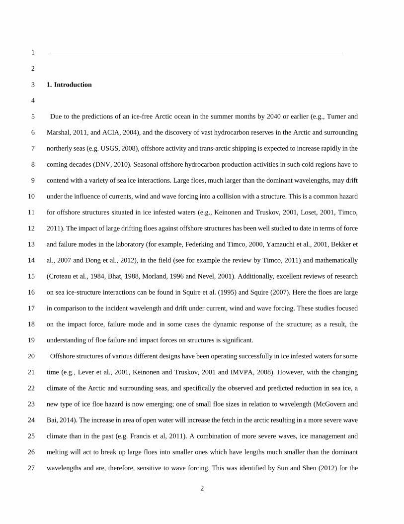
and positive throughout. Figure 10 shows the X-trace of the centre of gravity of a floe as a function of time in one 21
of the runs at λ/Lc = 15, H = 0.1 m in order to visualise this effect. Just after 1.5 mins the drift decreases sharply 22
to ~ 0. This is shown on Figure 10b where the period averaged Vd is plotted as a function of time. Vd remains at 23
~ 0 until about 2.5 mins by which time the floe has been laterally displaced off the centreline to be free of the 24
near-cylinder flow-field and its Vd reduction effect allowing Vd to increase and the floe to pass the cylinder. 25
26
Figure 10. The X displacement trace (a) and Vd (b) as a function of time respectively for the S20 model a run at λ/Lc = 15, H = 0.1 27

18
m. 1
2
At λ/Lc ≤ 8, this trapping in the lee of the cylinder was not observed. Floes would either impact the cylinder or 3
be deflected laterally with enough velocity and at a point far enough upstream to ensure that no impact was 4
possible by the time the floe drew level with the cylinder. In such cases Vd appeared unaffected. At λ/Lc = 6 no 5
impacts were observed either as the floes appeared much more susceptible to lateral motions and would be easily 6
deflected around the cylinder. 7
Generally it appeared that the shorter the λ the more likely the floe would impact, notwithstanding the results 8
for λ /Lc = 6. What became apparent when analysing these results, however, is that while the impact occurrence 9
may well be influenced by λ, the steepness of the wave H/λ must also be important. Considering that the Vd and 10
X/H of a floe in a given H will be greater the shorter the λ, as observed in the open water results in McGovern 11
and Bai (2014), a steeper wave would enable the floe to better overcome the retardation effect of the near-cylinder 12
flow field, resulting in a greater chance of impact. In order to investigate whether the influence of λ/Lc observed 13
above is dependent to the particular H/λ chosen (i.e., 0.033), two further tests were conducted in which for each 14
value of λ/Lc, three runs were recorded for H/λ = 0.043 and 0.053. In the interests of logistical brevity it was felt 15
that three runs each would suffice to indicate whether there was an influence. The results suggested the trend 16
indicated with H/λ = 0.033 of an increase in impacts with decreasing λ/Lc remains for these steeper waves. For 17
H/λ = 0.043 impacts were observed for λ/Lc = 9.4 (1 impact), 7 (5) and 4.6 (9) and for H/λ = 0.053 for λ/Lc = 11.2 18
(2), 9.4 (3), 7.5 (7), 5.6 (6) and 3.8 (10). 19
The results indicate that the longer the λ, the less able the floe is to overcome the near-cylinder flow field and 20
but that the greater H/λ the greater the impact occurrence regardless of λ. Using the average point for each λ/Lc at 21
which Vd reaches 0 or its lowest average value to be the closest the floe gets to the cylinder while still covering 22
the centreline, that influence can be investigated further. This was found to be a reasonable assumption as in all 23
the data, once Vd reached 0 the floe was subject to lateral motions that would eventually push it well off the 24
centreline, and for floes that impacted, Vd reduced to its lowest value just before impact. In Figure 11, closest x/D 25
position achieved by the floe defined in this way is plotted as a function of λ/Lc. 26
27

19
Figure 11. The mean value of normalised distance upstream from the cylinder x/D achieved by the floes in the three different H/λ 1
tested above as a function of λ/Lc. 2
3
It is difficult to draw concrete conclusions from Figure 11 due to the lack of sufficient data. Furthermore, the 4
data for H/λ =0.053 and 0.043 in particular are not averaged over a significant enough number of runs to give 5
any reasonable statistical credibility. However, it does loosely indicate that the lower the value of λ/Lc and the 6
greater the value of H/λ the closer the floe may get to the cylinder and therefore the greater the chance of an 7
impact occurring. Full parameterisation of this requires further detailed investigation including statistically 8
significant numbers of runs for each wave condition, as well as an investigation of the effect of different values 9
of D, which is not in the scope of the present study. 10
11
4. Irregular Waves 12
13
The wave driven floe-cylinder interaction is complex and we have sought in the above to elucidate the 14
similarities and difference in the kinematics in open water and near-cylinder, as well as the impact process. The 15
parametric influences on kinematic response in regular waves have been already well elucidated by McGovern 16
and Bai (2014) and have been shown to apply to the near-cylinder kinematics above. It, therefore, appeared that 17
to repeat such a study with the addition of a cylinder would not significantly add to that data. It would also result 18
in a lengthy experimental campaign to ensure that sufficient runs were made for each parameter set to provide 19
statistically meaningful results. With this in mind the best course of action was considered to progress the 20
parametric study using irregular waves. The conditions of the irregular waves are described in Section 2. 21
It is, however, useful to discuss the physical connection between regular and irregular wave floe kinematics and 22
impact occurrence. This connection can be made when it is considered that linear superposition of floe kinematic 23
response in linear, regular waves can accurately determine the motion response in irregular waves. Lever et al, 24
(1990a) discuss in detail the use of linear superposition of model iceberg RAO in regular waves to accurately 25
determine irregular wave response. They found significant motion responses in irregular waves matched well 26
with those calculated using linear superposition of regular wave response, even though large nonlinear model 27

20
response was commonly observed in regular waves. Comparisons with their regular wave model data and the 1
regular wave floe response data presented in McGovern and Bai (2014), showed floe kinematics to exhibit non-2
linear behaviour, but generally lesser magnitude and extent than iceberg kinematics. This was attributed to the 3
relatively flat, low draft geometry of floes in comparison to icebergs. As such, linear superposition of floe 4
response in regular waves ought to match well with those in irregular waves as well. It should be mentioned that 5
the following results are discussed at prototype scales. 6
7
4.1 Impact Behaviour in Irregular Waves 8
9
As a result of the relationship given by Eq. (5), the H/λ would be approximately 0.033. From the regular wave 10
results presented above, it appeared that S20 in irregular waves would not present many impacts. This was 11
confirmed when over 20 runs in Tp = 12 s, the S20 floe impacted only three times. Therefore, tests were run with 12
the S30 model in the view that this would present more impact events and therefore opportunity for analysis. 20 13
runs were recorded of S30 in irregular waves of Tp = 15.3 s and Hs = 12 m. Impacts occurred in 16 runs, including 14
5 double impacts. Table 5 presents the Vx, Vy (heave velocity) KEt and KEr of each impact converted to full scale 15
values. The mean values of Vx, Vy (0.71 and -0.17 m s-1) indicate a propensity for impacts to occur during foreword 16
and downward motion. However, there is a significant amount of scatter around these mean values, indicating 17
the impact behaviour is complex. A similar observation was made by Lever et al, (1990) in their study of iceberg 18
models impacting a floating semi-submersible. Following their analysis, a scatter plot which is not presented here 19
showed no correlation between Vx and Vy at impact suggesting they are independent random variables. From this 20
analysis and the observations of the RECAP data, it is clear that the impact occurred at random points in the wave 21
cycle. This is somewhat at odds with the regular wave data, which showed impacts to generally occur around the 22
middle point of the surge motion. However, it can be argued that the regular wave results therefore serve to 23
provide a conservative estimate of maximum impact velocity. 24
25
Table 5. The linear impact velocities and KE for each impact recorded of the S30 model in irregular waves of Hs = 12 m at 26
prototype scale. 27

21
1
The KE at impact is generally dominated by the translational portion, its mean is 0.74 MJ (Mega Joules) and 2
the standard deviation is 0.48 MJ. This indicates that impact KEt is reasonably consistent in this wave spectrum. 3
KEr has a smaller mean of 0.61 MJ, but a larger standard deviation of 1.22 MJ making it appear more variable. 4
The very large KEr values on impacts 4, 6, 13 and 15 are brought about by secondary impacts following a first, 5
more linear impact (numbers 3, 6, 12 and 14 respectively). In these cases the first impact, caused the floe to 6
rebound leeward and gain lateral displacement. In an analogous manner to the double hits described for regular 7
waves above, the floe eventually regains a net forward drift but is laterally displaced resulting in a second impact 8
off-centre with the floe exhibiting significant ω and yaw which caused the much higher KEr on the second impact. 9
Mean KEr not including the secondary impacts is 0.17 MJ which constitutes approximately 17 % of the mean 10
total KE. This implies rather like Lever et al (1990), who investigated iceberg impacts with a transparent semi-11
submersible, that impact KE is dominated by translational motions heave and surge. But in the case of single 12
slender cylinders, a first sufficiently off-centre impact may impart significant rotation on the floe and any 13
secondary impact will result in a significant amount of KEr that can be significantly greater than the KEt both for 14
the same impact, and generally when compared to approximately head-on impacts (for example, impacts 6, 13 15
and 15). The conclusion arrived at by Lever et al (1990) that KEr may be ignored in iceberg impact modelling 16
therefore only seems justifiable in the case of floes during first impacts. This data indicates that if the floe impacts 17
twice, it will likely do so on the second time with a significantly large KEr than before and therefore, KEr must 18
be taken into account. 19
Figure 12 shows a scatter plot of Vx and the |Vy| with KEt. The correlation between Vx and KEt appears strong 20
while Vy-KEt is rather more loosely correlated. This is not to say that heave motions do not contribute significantly 21
to the total KE, take for example impact 6 (Table 5), however, it appears that the overwhelming contribution is 22
from the surge motion, particularly in first, approximately head-on impacts. In steeper waves, it could be 23
hypothesised that heave contribution would increase, but this cannot be confirmed in the current data. 24
25
Figure 12. Plot of KE as a function of (a) Vx and (b) |Vy|. 26
27

22
4.2 The influence of Hs 1
2
To observe the influence of Hs on impact occurrence and KE, the S30 model was subject to 20 runs in irregular 3
waves of Hs = 10 m and 14 m (Table 1). In almost all runs the floe impacted at least once; for Hs = 14 m there 4
were 16 single impacts and one double, Hs = 12 m and 15 m single impacts and 3 doubles and Hs = 10 m there 5
were 13 single impacts and 5 doubles. Table 6 gives the key mean values for each Hs. There is a clear increase in 6
surge velocity between Hs = 10 m and 12 m as would be expected with increasing Hs though there is no change 7
between Hs = 12 m and 14 m. At first it appears that the same observation can be made for Vy, however, the mean 8
absolute values are approximately the same suggesting that the heave motion and its contribution to translational 9
velocity and KEt remains unaffected by Hs within the large values observed. While the data suggests broadly that 10
an increase in Hs will result in an increase in KE (along with the regular wave results above and in McGovern 11
and Bai (2014), which indicate larger H will result in larger velocities), KEt is the largest for Hs = 14 m due 12
mainly to the occurrence of several particularly heavy impacts. Apart from these, the remaining impacts have a 13
similar Vx and KEt to those in Hs = 12 m. This suggests that the inherent variability in irregular wave impacts is 14
significant and would require significantly more tests to elucidate the expected trends. 15
16
Table 6. The key mean values for the S30 model in 20 runs of Hs = 14, 12 and 10 m at prototype scale. 17
18
4.3 Influence of Lc 19
20
To investigate the influence of Lc the impact results of twenty runs with the S30 floe model were compared with 21
that of the S20 floe model in Hs = 12 m. Whereas S20 only impacted on three runs, the S30 model impacted a 22
total of 21 times including 3 doubles. Clearly the larger the cross section of S30 increases greatly the impact 23
occurrence with the S20 model appearing very sensitive to the near-cylinder flow field. As mean linear velocities 24
appeared quite similar (Table 7), this is likely due to its lower mass and, therefore, momentum than the S30 25
model. Visual observations and notes of each impact of S20 indicated that the impacts appeared to occur when 26
the floe was hit by one or more large wave when close to the cylinder. In impacts 1 and 2, a large wave resulted 27

23
in the floe being thrown against the cylinder, while in the third several larger waves enabled the floe to get very 1
close to the cylinder making an impact eventually inevitable. Many runs did not involve impacts but may well 2
have done had they received such a series of waves when close to the cylinder. It is difficult to draw conclusions 3
from so few impacts so it was decided to run additional tests with the S20 model in Hs = 14 m and 10 m, allowing 4
direct comparison with the S30 results in those Hs values. In total, 5 impacts were recorded for Hs = 14 m, 3 for 5
Hs = 12 m and 6 for Hs = 10 m. The mean surge and heave velocities and KE’s for the impacts of S20 and S30 6
are also given in Table 7. Clearly the mean values of the S20 impacts are subject to a greater degree of uncertainty 7
due to the significantly fewer impacts recorded. Such lack of impact data, though a function of the system, means 8
that there is not enough data to fully parameterise impact occurrence and KE with D/Lc. However, the main 9
conclusions drawn from this comparison are that the larger Lc and mass, the more likely the impact. 10
11
Table 7. The mean surge and heave velocities and KE’s for the S30 model in 20 runs of Hs = 14, 12 and 10 m at prototype scale. 12
13
4.4 Influence of Shape 14
15
To investigate the influence of floe shape on the impact characteristics, a series of twenty runs were repeated 16
for Hs = 12 m with a rectangle (R3020) and triangle (T30) floe. 20 runs were made for R3020 with its longest 17
side parallel to the incident waves (R3020p) and a further 20 runs with its longest side normal (R3020n). Table 18
8 presents the mean linear velocities and KE values. R3020p impacted 19 times in total, while R3020n impacted 19
only once. This is a significant difference for a change in floe upstream starting alignment. Regular wave open 20
water behaviour of rectangular floes of the same dimension (though with b = 0.05 m) showed heave response to 21
be dampened at lower λ but no indication of any reduction in surge (McGovern and Bai, 2014). As surge has 22
been defined above as the principle linear motion causing impacts, the difference in impact occurrence is not 23
likely to be due to the floe’s kinematic response but rather due to the near-cylinder flow field’s influence on the 24
floe. T30 impacted 4 times. During ten of the 20 runs, the floe was started orientated with one of its sided parallel 25
to the incident waves, while in the remaining ten runs it was orientated so its corner was streamlines to the incident 26
waves. In all tests, the floe rotated to a new position, but this was always with the side parallel to the incident 27

24
waves. It appeared that because the floe ended up approaching the cylinder with its corner-first, it was subject to 1
strong lateral displacements by the near-cylinder floe field and often missed. When it did impact, it was generally 2
quite light and off-centre, leading to the relatively low KE values observed in Table 8. The suggestion is, 3
therefore, cross sectional area is important both in terms of a larger area having more chance to hit, but also 4
because a smaller cross section will be more responsive to the reflected waves pushing it laterally than the large 5
one. 6
7
Table 8. The mean surge and heave velocities and KE’s for the R3020p, R3020n and Tri30 models in 20 runs of Hs = 12 m at 8
prototype scale. 9
10
5. Conclusions 11
12
This study builds upon a previous study by McGovern and Bai (2014) which detailed open water (i.e., with no 13
structure in the floes path) floe drift and oscillating velocities as well as the influence of shape, b, r, λ and H in 14
regular waves. The aim was to investigate using the same methodology the effect of a single slender cylinder on 15
the upstream, near-cylinder, impact and post impact kinematics and velocities of floes of various different shapes 16
in a variety of wave conditions. It was performed with a view to understanding the KE of the floe during an 17
impact event, as this has been shown by Timco (2011) to have a simple yet accurate functional relationship with 18
the impact force applied to a structure by an impacting floe. To achieve this, a series of scaled model tests were 19
carried out. The validation of scale ratios from McGovern and Bai (2014) was first discussed and applied to the 20
current tests. The scaled flume data may with caution be extrapolated to the equivalent prototype using Froude 21
scaling criteria. 22
By using HDPE floe models a comparison with the wax model open water results of McGovern and Bai (2014) 23
showed that the higher ρ HDPE kinematic behaviour as a function of λ/Lc was similar to the wax model while 24
experiencing resonances in heave response at longer λ. The results suggest the role of ρ would benefit from further 25
clarification in future investigations. 26

25
The upstream floe kinematics were analysed to identify what the effect of the cylinder was on the floe and where 1
this began. Upstream heave and surge motions appeared unaffected by the cylinder at distances of ~ ≥ 10D. At 2
x/D ≤ 10 the heave response showed a marginal increase, though no resonance was observed. This was 3
hypothesized to be due to one or both of reflected waves from the cylinder and the adverse pressure gradient that 4
forms along the lee-face of the cylinder increasing the heave motion slightly. Surge showed a marked reduction 5
at x/D ≤ 10 regardless of whether there was an impact, or whether the floe was deflected away from the structure 6
before an impact. This was clearly observed in the variation of Vd; for head-on floe approaches very low and 7
negative velocities were observed. 8
3D analysis of the impact process was employed to extract the full six-degree-of-freedom motion of the floe, its 9
linear velocity at the centre of gravity, and its angular velocities at the point of impact on the floe for each impact 10
observed in the test program. Broadly speaking, two main types of impact were observed; the first was relatively 11
head on and caused the floe to impact with a larger linear velocity, and hence KEt than impacts that occurred 12
when the floe had a relatively large angle of yaw. In which case, ω and KE were often more significant, and 13
particularly in the case of secondary impacts, notably larger than linear velocity and KEt. The impact behaviour 14
in irregular waves was found to be highly variable occurring at different points in the wave cycle. KEt was shown 15
to be the dominant portion of total KE for most cases. However, as observed in regular waves, secondary impacts 16
often exhibited very large KEr. 17
The influence of λ/Lc, H/λ and for irregular waves, Hs on impact occurrence and was investigated. H/λ did not 18
appear to have a significant effect on impact occurrence, with KE increasing linearly with increasing H. The 19
results also indicated that the lower the λ the closer the floe would get to the cylinder and hence the greater the 20
chance of impact. Even though extensive tests were run (10 runs for each change in wave parameter, and 20 for 21
each Hs) the variability in results, particularly in irregular waves indicated that further, statistically significant 22
work may be required to fully parameterise the effect of λ/Lc and H/λ in impact occurrence, as well as the effect 23
of D. 24
The influence of Lc and shape were investigated in irregular waves. The results indicated the larger Lc was, the 25
greater the impact occurrence and KE (in the case of floes with greater mass). With shape, a rectangle and triangle 26
were observed in different starting orientations. The results suggested that cross sectional area relative to the 27

26
cylinder was important; the larger its value the more likely it would impact. This was attributed to the lesser 1
influence of the near-cylinder floe field on a wider approaching floe. 2
3
6. References 4
5
[1] Allyn, N., Lima, S., Croasdale, K., Wright, B. and Jordaan, I.J. (2001). “Application of Offshore Codes to the Grand 6
Banks Region.” Proceedings, POAC 01, Ottawa, Canada, 1, 453-467. 7
[2] Arctic Climate Impact Assessment (ACIA), (2004). “Impacts of a Warming Arctic.” Cambridge University Press. 8
[3] Arunachalam, V. M., Murrray, J. J. and Muggeridge, D. B. (1987). “Short Term Motion Analysis of Icebergs in Linear 9
Waves.” Cold Reg. Sci. Tech. 13, 247 – 258. 10
[4] Bekker, A. T., Sabodash, O. A. and Shubin, O. A. (2007). “Generalized Mathematical Model of Extreme Ice Loads on 11
Offshore Engineering Structures in Frozen Seas.” Proc. 17th Int. Offshore and Polar Engineering Conf. 723-729. 12
[5] Bhat, B. U. (1988). “Analysis for Splitting of Ice floes during Summer Impact.” Cold Reg. Sci. Tech. 15, 53-63. 13
[6] Croteau, P., Rojansky, M. and Gerwick, B. C. (1984). “Summer Ice Floe Impacts Against Caisson-Type Exploratory and 14
Production Platforms.” J. Energy Res. Tech. 106, 169-175. 15
[7] DNV, (2010). “Shipping across the Arctic Ocean - A Feasible Option in 2030–2050 as a Result of Global Warming?” 16
Position Paper 04–2010. 17
[8] Dong, J., Li, Z., Lu, P., Jia, Q., Wang, G., and Li, G. (2012). “Design Ice Load for Piles Subjected to Ice Impact.” Cold 18
Reg. Sci. Tech. 71, 34-43. 19
[9] Federking, R. and Timco, G. (2000). “Sea Ice Floe Impacts – Large Scale Basin Experiments.” Proc. 10th Int. Conf. Port 20
and Ocean Engineering under Arctic Conditions. 1, 640-645. 21
[10] Francis, O.P., Panteleev, G.G. and Atkinson, D.E. (2011). “Ocean Wave Conditions in the Chukchi Sea from Satellite and 22
in Situ Observations.” Geophys Res. Let. 89, 8069–8079. 23
[11] Hughes, S. A. (1993). “Physical Models and Laboratory Techniques in Coastal Engineering.” Advanced Series on Ocean 24
Engineering. Vol. 7. World Scientific, Singapore. 25
[12] IMVPA, (2008). “Arctic Offshore Technology Assessment of Exploration and Production Options for Cold Regions of 26
the US Outer Continental Shelf.” Project No. C-0506-15. 27
[13] Isaacson, M. and McTaggart, K. A. (1990). “Modelling of Iceberg Drift Motions near a Large Offshore Structure.” Cold 28
Reg. Sci. Tech. 19, 47-58. 29
[14] Keinonen A. and Truskov, P. (2001). “Offshore Operations in Ice for Sakhalin 2, Phase 1.” Proc. 16th Int. Conf. Port and 30

27
Ocean Engineering under Arctic Conditions. 1
[15] Kwok, R. and Rothrock, D. A. (2009). “Decline in Arctic Sea Ice Thickness From Submarine and ICES at Records: 1958–2
2008.” Geophys. Res. Lett. 36, L15501. 3
[16] Kristensen, M., Squire, V. A. and Moore, S. C. (1982). “Tabular Icebergs in Ocean Waves.” Nature. 297, 669-671. 4
[17] Leblond, P. H., Calisal, S. M. and Isaacson, M. (1982). “Wave Spectra in Canadian Waters.” Can. Contract. Rep. Hydrogr. 5
Ocean Sci. 6:57, p + 134 p. Appendices. 6
[18] Lever, G. V., Kean, J. R. and Muggeridge, K. J. (2001). “Terra Nova FPSO on the Grand Banks of Canda.” Proc. 16th Int. 7
Conf. Port and Ocean Engineering under Arctic Conditions. 3-20. 8
[19] Lever, J. H. and Diemand, D. (1985). “Measurements of Instantaneous Motions of Ice Masses at Sea: 1984 Pilot Program.” 9
Proceedings of the 8th International Conference on Port and Ocean Engineering Under Arctic Conditions. 2, Narsarsuaq, 10
Greenland. 11
[20] Lever, J. H., Klein, K., Mitchell, D. and Diemand, D. (1991). “Wave-induced Iceberg Motion.” Cold Reg. Sci. Tech. 20, 12
11-23. 13
[21] Lever, J. H., Reimer, E. and Diemand, D. (1988). “A Model Study of the Wave-Induced Motion of Small Icebergs and 14
Bergy Bits.” J. Offshore Mech. Arct. Eng. 110, 101-107. 15
[22] Lever, J. H., Colbourne, B. and Mak, L. (1990). “Model Study of the Wave-Driven Impact of Bergy Bits with a Semi-16
Submersible Platform.” J. Offshore Mech. Arct. Eng. 112, 313 – 322. 17
[23] Lever, J. H., Sen, D. and Attwood, D. (1990a). “The Influence of Shape on Iceberg Wave-Induced Velocity Statistics.” J. 18
Offshore Mech. Arct. Eng. 112, 263 – 296. 19
[24] Loset, S. (2001). “Research Needs for the Development of the Barents Sea.” Proc. 16th Int. Conf. Port and Ocean 20
Engineering under Arctic Conditions. 21
[25] Masson, D. and LeBlond, P. H. (1989). “Spectral Evolution of Wind-Generated Surface Gravity Waves in a Dispersed Ice 22
Field.” J. Fluid Mech. 202, 43-81. 23
[26] McGovern, D. J. and Bai, W. (2014). “Experimental Study on Kinematics of Sea Ice Floes in Regular Waves.” Cold Reg. 24
Sci. Tech. 103, 15-30. 25
[27] Meylan, M. H. (2002). “Wave Response of an Ice Floe of Arbitrary Geometry.” J. Geophys. Res. 107 (C1), 3005. 26
[28] Meylan, M.H. and Squire, V.A., (1994). “The Response of Ice Floes to Ocean Waves.” J. Geophys. Res. 99 (C1), 899–27
900. 28
[29] Meylan, M.H. and Squire, V.A., (1996). “Response of a Circular Ice Floe to Ocean Waves.” J. Geophys. Res. 101 (C4), 29
8869–8884. 30
[30] Morland, L. W. (1996). “Dynamic Impact between a Viscoelastic Ice Floe and a Rigid Structure.” Cold Reg. Sci. Tech. 24, 31

28
7-28. 1
[31] Moslet, P. O. (2008). “Medium Scale Ice-Structure Interaction.” Cold Reg. Sci. Tech. 54, 143-152. 2
[32] Murray, J. J., Guy, G. B. and Muggeridge, D. B. (1983). “Response of Modelled Ice Masses to Regular Waves and 3
Regular Wave Groups.” Proceedings of the International Conference on Oceans, 2, San Fransisco, 1048 – 1052. 4
[33] Neu, H. J. A. (1982). “11-year Deep-Water Wave Climate of Canadian Atlantic Waters.” Canadian Technical Report of 5
Hydrography and Ocean Sciences 13. 6
[34] Nevel, D. (2001). “First Year Ice Ridge Acting on Conical Structures.” Proc. 16th Int. Conf. Port and Ocean Engineering 7
under Arctic Conditions. 369-374. 8
[35] Shirasawa, K., Eicken, H., Tateyama, K., Takatsuka and T., Kawamura, T. (2009). “Sea-Ice-Thickness Variability in the 9
Chukchi Sea, Spring and Summer 2002–2004.” Deep-Sea Res. II, 56, 1182-1200. 10
[36] Squire, V. A. (2007). “Of Ocean Waves and Sea-Ice Revisited.” Cold Reg. Sci. Tech. 49, 110-133. 11
[37] Squire, V.A. (1984). “A Theoretical, Laboratory, and Field Study of Ice-Coupled Waves.” J Geophy. Res. 89, 8069–8079. 12
[38] Squire, V.A., Dugan, J.P., Wadhams, P., Rottier, P.J. and Liu, A.K. (1995), “Of Ocean Waves and Sea-ice.” Ann. Rev. of 13
Fluid Mech. 27, 115-168. 14
[39] Sumer, B. M. and Fredsøe, J. (2006). “Hydrodynamics around Cylindrical Structures.” Advanced Series on Ocean 15
Engineering. Vol. 12. World Scientific, Singapore. 16
[40] Sun, S. and Shen, H. H. (2012). “Simulation of Pancake Ice Load on a Circular Cylinder in a Wave and Current Field.” 17
Cold Reg. Sci. Tech. 78, 31-39. 18
[41] Timco, G. W., (2011). “Isolated Floe Impacts.” Cold Reg. Sci. Tech. 68, 35-48. 19
[42] Timco, G. W. and Obrien, S. O. (1994). “Flexural Strength Equation for Sea Ice.” Cold Reg. Sci. Tech. 22, 285-298. 20
[43] Timco, G. W. and Federking, R. M. W. (1996). “A Review of Sea Ice Density.” Cold Reg. Sci. Tech. 24, 1-6. 21
[44] Turner, J. and Marshall, G. J. (2011). “Climate Change in the Polar Regions.” Cambridge University Press, Cambridge, 22
U.K. 23
[45] U.S. Geological Survey (USGS). (2008). “Circum-Arctic Resource Appraisal: Estimates of Undiscovered Oil and Gas 24
North of the Arctic Circle.” U.S. Geological Survey Fact Sheet 2008-3049. 25
[46] Wadhams, P., Kristensen, M. and Orheim, O. (1983). “The Response of Antarctic Icebergs to Ocean Waves.” J. Geohys. 26
Res. 88 (C), 6053-6065. 27
[47] Wang, C.D. and Meylan, M.H. (2004). “A Higher-Order-Coupled Boundary Element and Finite Element Method for the 28
Wave Forcing of a Floating Elastic Plate.” J. Fluid Stru. 19, 557-572. 29
[48] Williams, T.D. and Squire, V.A. (2006). “Scattering of Flexural–Gravity Waves at the Boundaries between Three Floating 30
Sheets with Applications.” J. Fluid Mech. 569, 113–140. 31

29
[49] Xie, H., Ackley, S. F., Yi, D., Zwally, H. J., Wagner, P., Weissling, B., Lewis, M. and Ye, K. (2011). “Sea-Ice Thickness 1
Distribution of the Bellingshausen Sea from Surface Measurements and ICESat Altimetry.” Deep-Sea Res. II. 58, 1039-2
1051. 3
[50] Yamauchi, Y. and Kamesaki, K. (2001). “First Year Ridge Acting on a Vertical Sided Structure Placed in Shallow Water.” 4
Proc. 16th Int. Conf. Port and Ocean Engineering under Arctic Conditions. 5

Figure - 1
Figure 1. Schematic diagram of the flume layout.

Figure - 2
Figure 2. A segment of time series from run in H = 0.14 m, T = 1.08 s showing the four LED traces experiencing an impact
event. The sharp change in the x and z traces is clearly observed at the point of impact (vertical dashed black line).
13125 13175 13225 13275 13325 13375-0.25
-0.2
-0.15
-0.1
-0.05
0
0.05
0.1
0.15
0.2
Time [s]
Dis
plac
emen
t [m
]
z trace
y trace
x trace
Impact frame

Figure - 3
Figure 3. Comparison between the heave (a) and surge (b) RAO as a function of λ/Lc for the S30 HDPE model and the
equivalent wax model used in McGovern and Bai (2013).
0 2 4 6 8 10 12
0.8
1
1.2
1.4
1.6
λ/Lc
Y/H
0 2 4 6 8 10 120.2
0.4
0.6
0.8
1
1.2
λ/Lc
X/H
HDPEWax (McGovernand Bai)
(a)
(b)

Figure - 4
Figure 4. The upstream heave (a) and surge (b) RAO averaged over x/D windows of 10D segments upstream of the cylinder.
0 2 4 6 8 100
0.5
1
λ /Lc
Y/H
0 2 4 6 8 100.5
1
1.5
2
λ /Lc
X/H
RAO x/D > 30RAO x/D 20 - 30RAO x/D 10 - 20RAO x/D 0 - 10
(b)

Figure - 5
Figure 5. The heave (a-b for S20 and S30 respectively) and surge (c-d for S20 and S30 respectively) RAO as a function of
x/D over ten runs in waves of H = 0.14 m and T = 1.3 s. The leading edge of the cylinder is located at x/D = 0. For runs that
result in impacts these occur at ~ 2D and 3D for the S20 and S30 models respectively.
0 10 20 30 400
0.5
1
x/D
Y/H
S20
run 1run 2run 3run 4run 5run 6run 7run 8run 9run 10
-10 0 10 20 30 400
0.5
1
x/D
Y/H
S30
0 10 20 30 400
0.5
1
1.5
x/D
X/H
-10 0 10 20 30 400
0.5
1
1.5
x/D
X/H
(c)
(a) (b)
(d)

Figure - 6
Figure 6. The Vd as a function of x/D over ten runs in waves of H = 0.14 m and T = 1.3 s for the S20 (a) and S30 (b) models.
The leading edge of the cylinder is located at x/D = 0.
-5 0 5 10 15 20 25 30 35 40-10
0
10
20
x/D
V d [cm
s-1
]
-5 0 5 10 15 20 25 30 35 40-20
-10
0
10
x/D
V d [cm
s-1
]
Run 1Run 2Run 3Run 4Run 5Run 6Run 7Run 8Run 9Run 10
(b)
(a)

Figure - 7
Figure 7. Plots showing the near head-on impact of S30 with the cylinder during run 2 in the (a) x-z plane, (b) x-y plane and
(c) three dimensions. The cylinder is represented as a bold black circle on (a), with the floe edge outline given as a square and
the displacement as a function of time of the floe’s centre of gravity is given as the black line. In (b) and (c) the cylinder is a
solid black line with a thickness equal to D while the floe outline is filled grey and in (b) the displacement as a function of
time of the floe’s centre of gravity is given as the black line.

Figure - 8
Figure 8. Plots showing the double impact of S30 with the cylinder during run 4 in the (a, d) x-z plane, (b, e) x-y plane and (c,
f) three dimensions. The cylinder is represented as a bold black circle on (a, d), with the floe edge outline given as a square
and the displacement as a function of time of the floe’s centre of gravity is given as the black line. In (b, e) and (c, f) the
cylinder is a solid black line with a thickness equal to D while the floe outline is filled grey and in (b, e) the displacement as a
function of time of the floe’s centre of gravity is given as the black line.

Figure - 9
Figure 9. (a) A histogram of the number of impacts recorded as a function of H/λ, and (b) KE as a function of H/λ.
0.08 0.06 0.04 0.020
1
2
3
4
5
6
7
8
9
10
H/λ
Num
ber o
f Im
pact
s O
ver T
en R
uns
0.02 0.03 0.04 0.05 0.06 0.07 0.080
2
4
6
8
10
12
H/λ
KE
[MJ]
Translational KERotational KE
(a) (b)
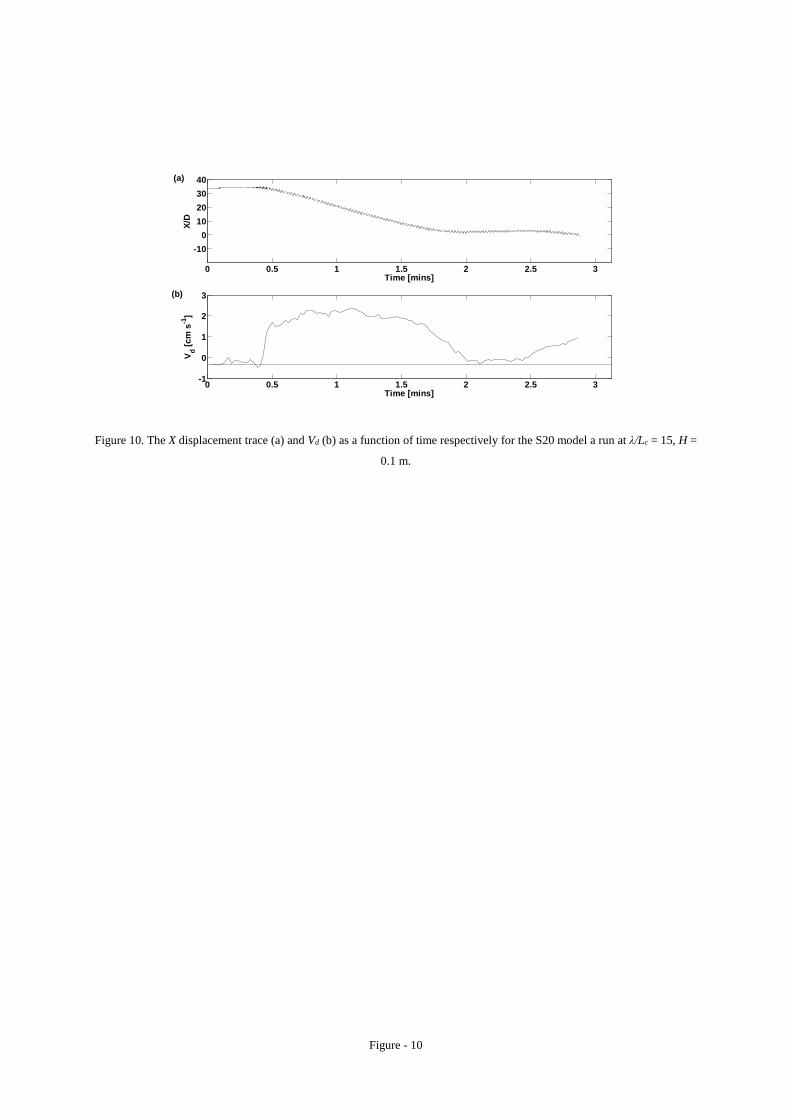
Figure - 10
Figure 10. The X displacement trace (a) and Vd (b) as a function of time respectively for the S20 model a run at λ/Lc = 15, H =
0.1 m.
0 0.5 1 1.5 2 2.5 3
-100
10203040
Time [mins]
X/D
0 0.5 1 1.5 2 2.5 3-1
0
1
2
3
Time [mins]
V d [cm
s-1
]
(b)
(a)

Figure - 11
Figure 11. The mean value of normalised distance upstream from the cylinder x/D achieved by the floes in the three different
H/λ tested above as a function of λ/Lc.
0 5 10 15 20 252
4
6
8
10
12
14
16
18
λ/Lc
x/D
H/λ = 0.033H/λ = 0.043H/λ = 0.053
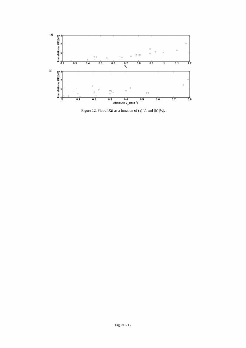
Figure - 12
Figure 12. Plot of KE as a function of (a) Vx and (b) |Vy|.
0.2 0.3 0.4 0.5 0.6 0.7 0.8 0.9 1 1.1 1.20
1
2
3
Vx
Tran
slat
iona
l KE
[MJ]
0 0.1 0.2 0.3 0.4 0.5 0.6 0.7 0.80
1
2
3
Absolute Vy [m s-1]
Tran
slat
iona
l KE
[MJ](b)
(a)