experimental study of the heat transfer in porous semitransparent heat-shield materials
TRANSCRIPT
EXPERIMENTAL STUDY OF THE HEAT TRANSFERIN POROUS SEMITRANSPARENT HEAT-SHIELD MATERIALS
L. Ya. Paderin,a P. V. Prosuntsov,b
S. V. Reznik,b and V. P. P. FishercUDC 629.7.018.3:536.24+536.33
Studies of the stationary heat transfer and effective heat conductivity of two materials in the temperaturerange T = 573–1473 K and the air-pressure range p = 1–105 Pa have been made. A comparative analysisof the heat transfer in them and other porous materials is given.
Introduction. The specificity and difficulty of investigation of the heat transfer in porous materials is that inthem all three kinds of heat transfer take place simultaneously: the contact-conductive heat transfer (qc) through thesolid phase forming the frame of the material and the radiation (qr) and molecular (qg) heat transfer through the gasphase in the gas–solid state system in pores. The contribution of each of the above kinds to the total heat transfer de-pends on their chemical composition, the physical structure of the material, the temperature levels and gradients in thematerial, and the pressure of the gaseous medium in which the material is used.
A large volume of various studies, both theoretical and experimental, devoted to the heat transfer in poroussemitransparent materials and the determination of their effective heat conductivity and its separate components havealready been made (see, e.g., 1–14]. Within the framework of calculation-theoretical studies one usually uses a gener-alized mathematical model representing a set of individual models describing each of the above kinds of combinedheat transfer in the materials being considered. In so doing, a large part of the above works pertains to investigationsof the radiation heat transfer, since at higher temperatures and in rarefied media its contribution to the total heat trans-fer is comparable to the conductive-molecular heat transfer is or even prevailing. Two approaches to the problem ofmathematical modeling of the radiation heat transfer — an electrodynamic and a thermodynamic approach — are note-worthy [1–4]. The first of them is based on the investigation of the interaction of electromagnetic waves with ensem-bles of fibers (particles) of the substance with the use of the equations of classical electrodynamics [1–3]. Thecooperative effects within the framework of this approach are described by the theory of multiple scattering of waves[13]. Within the framework of the second (thermodynamic) approach, the material being investigated is considered asa quasi-homogeneous macrosystem, and the radiation heat transfer is described by the equation of the radiation transferin an absorbing, a radiating, and a scattering medium or by the equation of the photon diffusion in an attenuating me-dium [3, 4]. Each approach uses its characteristics to describe the optical properties of materials.
Because of the complex structure of porous partially transparent materials and the insufficient knowledge ofthe physical phenomena being investigated, the works in the field of mathematical modeling of the radiation heattransfer are approximate and are carried out with the use of many simplifying assumptions. At the same time, theymake it possible to estimate the qualitative influence of the structure parameters, in particular, the diameter and orien-tation of fibers, on the radiation heat transfer and the growth of its role in the total heat transfer with increasing tem-perature in the investigated materials and determine the optimal diameters of fibers depending on the temperature andtheir orientation with respect to the direction of the heat flow in the material [5, 7, 10].
In analyzing the radiation heat transfer in absorbing and scattering media, it is customary to use the dimen-sionless parameter called the optical thickness of the layer, τ = L ⁄ lf. The case where τ >> 1 corresponds to the modelof an optically thick layer and the case where τ ≤ 1 — to that of an optically thin layer. The intermediate values ofthe parameter τ correspond to the model of the sliding radiation.
Journal of Engineering Physics and Thermophysics, Vol. 78, No. 1, 2005
aProf. N. E. Zhukovskii Central Aerohydrodynamics Institute, 1, Zhukovskii Str., Zhukovskii, 140160, MoscowRegion, Russia; email: [email protected]; bN. E′ . Bauman Moscow State Technical University; cEuropean AeronauticDefense and Space Company (EADS Company), Bremen, Germany. Translated from Inzhenerno-Fizicheskii Zhurnal,Vol. 78, No. 1, pp. 60–66, January–February, 2005. Original article submitted September 21, 2004.
1062-0125/05/7801-0060 2005 Springer Science+Business Media, Inc.60
In applied studies of the radiation heat transfer and the effective heat conductivity of dispersive materials, themodel of an optically thick layer is widely used. For this case, the following relations for the radiation heat-conduc-tivity coefficient λr within the framework of the electrodynamic and thermodynamic approaches have been obtained:
λr = 163
n
2
κσT
3 , (1)
λr = 163
σT3lf . (2)
Comparing relations (1) and (2) obtained by different methods, one must note, first of all, the cubic tempera-ture dependence of the values of λr. In both approaches, to determine the radiation heat-conductivity coefficients, it isnecessary to have the values of the attenuation coefficient κ and the refractive index n or the mean free path of pho-tons lf.
The problems of investigating the contact-conductive and gaseous components of the heat transfer in the ma-terials being considered and the corresponding components of their effective heat conductivity are just as difficult. Atthe present time, there are no adequate models that permit identifying the frames formed by fibers (particles) and thecontact thermal resistances between the fibers, which makes it impossible to estimate theoretically both the contact-conductive and the gaseous components, and, consequently, the total heat transfer in the material and its effective heat-conductivity coefficient. In this connection, in investigating and determining qc and qg in real dispersive heat-shieldmaterials, which, as is known, have an irregular structure of the solid phase, experimental studies and empirical ap-proaches based on them are used.
In view of the foregoing, it can be stated that the basic method for investigating heat transfer in porous semi-transparent materials consists of thermophysical experiments, and the calculation data obtained on the basis of modernmathematical models require experimental verification and determination of the field of their application.
In contemporary practice in project and engineering thermal calculations, the heat transfer in the structural ele-ments from such materials is estimated mainly by means of numerical calculations of the nonlinear heat-conductionequations with the use of the effective values of the heat conductivity coefficients of the materials, and, in so doing,all three components of the heat transfer are taken into account additively. The temperature and barometric depend-ences of the above coefficients are determined by experimental methods.
At the present time, to investigate the heat transfer and determine the effective heat-conductivity coefficientsof the materials under consideration, the method of a heated plate with a compensation of thermal leakages from themain heater and the flat samples being investigated is widely used [6, 8, 12]. In accordance with this method, in themeasuring device a one-dimensional heat flow is created in the samples being investigated between the heated and thecooled sides. The measuring device is placed in a thermal vacuum chamber with a controlled composition and pressureof the gaseous medium, which permits investigating its influence on the heat transfer in the material.
Method and Facility for Investigating the Heat Transfer and Determining the Effective Heat-Conductiv-ity Coefficients of Heat-Insulating Materials. We propose a new version of the method for investigating the heattransfer and the effective heat conductivity of porous heat-insulating materials. The experimental facility is schemati-cally represented in Fig. 1.
The main part of the facility is a vacuum chamber with a measuring device located in its working volume. Itincorporates a system of regulated flat ohmic main heaters — the central heater No. 1, the upper heater No. 2, andthe lower heater No. 5. These heaters provide the given mean temperature and temperature drops in identical investi-gated samples arranged one-dimensionally about heater No. 1 and the compensation side heater Nos. 3, 4, and 6 pro-viding, jointly with the side heat insulation, elimination of thermal leakages from the samples and heater No. 1 and asimultaneous heat flow in the samples. Between the main heaters and the samples, as well as between the heaters andthe insulation, metal plates prepared by thermocouples are placed. On each plate, from four to six thermocouples areinstalled. By the temperature measurement data of the plates the temperatures of the sample surfaces adjoining theplates are determined.
61

The investigated samples, heater Nos. 1, 2, and 5, and the metal plates placed between them are of size 0.15× 0.15 × h m3. The side heater Nos. 3, 4, and 6 and the metal plates adjoining them, as well as the heat insulationbetween them, are made in the form of square frames with internal sizes of 0.152 × 0.152 m2 and outer sizes of 0.27× 0.27 m2. The thickness of the side insulation is equal to the thickness of the investigated sample h = 0.001–0.06 m.Outside (on the side, lower, and upper surfaces), the system consisting of samples, heaters, metal plates, and heat in-sulation is additionally covered with a heat-insulating layer of thickness 0.04 m. If necessary, the sizes of the sampleand other elements of the device can be changed.
The above elements — samples, heaters, metal plates, and heat insulation — are placed on a frame equippedwith a spiral compressing device performing a double function. First, it stabilizes the contacts of metal plates with thesample and the heater. Second, in investigating deformable materials, e.g., cotton, it ensures the given density of thesample and its thickness in the above range of h.
The infrastructure of the facility includes the following systems:(a) a system of evacuation and controlled puffing of gases (air, nitrogen, carbon dioxide, inert gases) into the
chamber ensuring the given composition and pressure of the gaseous medium in the chamber in the 1–105-Pa range;(b) an electric power-supply system that ensures autonomous regulated operation of the six heaters under auto-
matic or manual control;(c) an information-measuring system incorporating means for measuring the temperature (up to 50 thermocou-
ples), the gas pressure in the chamber, and the power of the heaters, as well as a computer for experimental informa-tion processing and heater power control in the automatic regime.
In the process of test preparation, the assembled measuring device is placed in the vacuum chamber, then itis connected to the power-supply system and the systems for measuring the temperatures of the metal plates and theheater No. 1 power. Then the chamber is sealed and the given composition and gas pressure are created in it.
During tests, the energy supply to the heaters upon heating and reaching the steady-state regime is regulatedso as to maintain equality of temperatures of the metal plates and frames positioned in one plane, T1u = T3u, T1low =T3low, T2 = T4, T5 = T6, as well as the temperature difference in the samples ∆Tu,c = ∆T1c ≤ 100oC. In so doing, inthe chamber the given pressure of the gaseous medium is set and maintained. The regime is considered to be station-ary when the readings of all thermocouples are stabilized and the electric power N of the main heater No. 1 and thechamber pressure are held constant within the instrumental measurement errors. After that, the readings of all devicesare registered and a transition to the next regime is made.
Fig. 1. Schematical representation of the experimental facility for investigatingthe heat transfer in porous semitransparent materials: 1) sample being investi-gated; 2) metal plate; 3) insulation; 4) thermocouples; 5) heaters.
62
Since in real designs complete elimination of thermal leakages is impossible, the design of the measuring de-vice and the testing procedure and its information support make it possible to not only minimize and control thermalleakages from samples in heater No. 1, but, if necessary, estimate them. Two types of thermal leakages from the in-vestigated samples in heater No. 1 are possible: though the side insulation qleak1 and over the commutation wires con-necting the heater to the external power supply circuit qleak2. These leakages are estimated in each experiment andtaken into account in calculating the heat flows passing through the samples. Thus, the quanti ty qtot = N −qleak1 − qleak2. Analysis has shown that in view of the above estimates the contribution of thermal leakages to the totalerror of determining the thermal flow passing through the samples does not exceed 1.2%.
The heat-conductivity coefficient λeff of the samples being investigated in the stationary regime is determinedfrom the relation
λeff = qtoth ⁄ S (∆Tu,c + ∆T1c) .
Our facility can be used to investigate the heat transfer and heat conductivity of materials in the temperaturerange of T = 400–1000 K and in the range of pressures of an inert and an air gaseous medium of p = 1–105 Pa. Inthe air medium, investigations are carried out at temperatures up to T = 1500 K. The measurement errors for the ef-fective heat-conductivity coefficients of the investigated samples are 5–7%.
In the process of tests on the facility, replication in the samples of both stationary and dynamic regimes pro-viding variation of the space and time gradients (temperature drops in samples from 0 to 1500 K, heating rates from0 to 10 K/sec) is possible. This makes it possible to determine:
(a) the influence of the structural parameters, the thermophysical and radiative characteristics of the experi-mental samples, and the internal space and time gradients in them on the total heat transfer and its components, aswell as the effective heat conductivity of the materials of the samples;
(b) the contribution of the gaseous component to the total heat transfer in materials depending on the tempera-ture, composition, and pressure in the gaseous medium;
(c) the possibilities of using the temperature dependences of the effective heat-conductivity coefficients ob-tained by the stationary method for specific materials in the calculations of their nonstationary thermal regimes, and, ifnecessary, making corrections of the values of the effective heat-conductivity coefficients as applied to concrete dy-namic regimes;
(d) the degree of confidence of the results of the determination of the effective heat-conductivity coefficientsor individual components of these coefficients obtained with the use of new theoretical or empirical approaches forparticular materials.
Test Data. As examples, Fig. 2 shows the results of testing two fibrous flexible heat-insulating materials. Thesamples had the same thickness h = 0.02 m and density ρ = 120 kg/m3 and were made on the basis of fibers fromaluminum oxide with the addition of an insignificant amount of silicon oxide (material No. 1) and from pure silicon
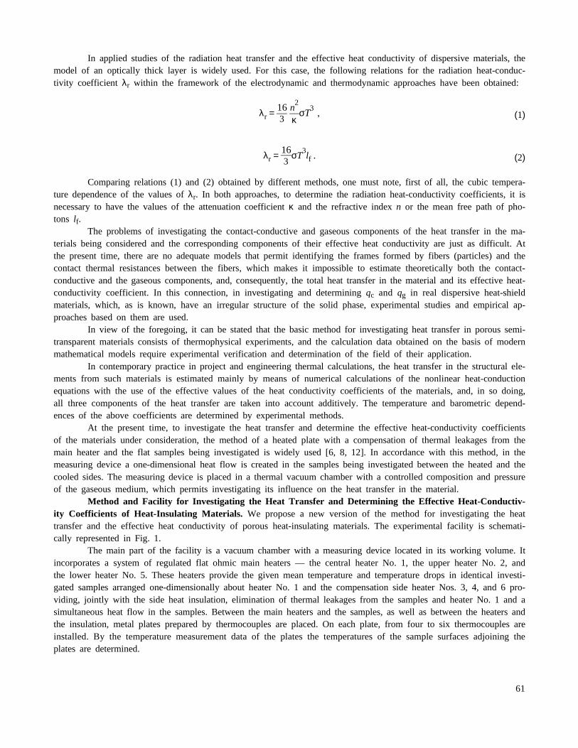
Fig. 2. Temperature (a) and barometric (b) dependences of the effective heat-conductivity coefficients: 1) material No. 1; 2) material No. 2.
63

oxide (material No. 2). Tests were carried out in vacuum and in an air medium at atmospheric and intermediate pres-sures.
Figure 2 gives the temperature dependences of the effective heat-conductivity coefficients λeff = f(T) in vac-uum and in an air medium at atmospheric pressure and the barometric dependences λeff = f(P) for the investigated ma-terials.
From the data presented, it follows that the value of λeff for both materials increases monotonically (as non-linear functions) with increasing temperature and air pressure in the chamber. In so doing, in the temperature range T= 573–1473 K the values of λeff of material No. 1 are higher than those of material No. 2 by a factor of 1.25–1.45in vacuum and by a factor of 1.2–1.25 at atmospheric pressure.
The increase in λeff with increasing temperature is explained mainly by the intensification of the radiation heattransfer and its gaseous component with increasing air pressure. In particular, in vacuum, in the investigated tempera-ture ranges, the λeff value for material No. 1 increases 11 times and for material No. 2 — 6.5 times, whereas at at-mospheric pressure it increases 4 and 3 times, respectively.
In considering the data presented in Fig. 2b, it is seen that the effective heat-conductivity coefficients of thematerials in the gaseous medium increase mainly in the pressure range p = 102–105 Pa, where the value of λeff in-creases 4.1 and 1.5 times for material No. 1 and 4.4 and 1.9 times for material No. 2 at temperatures T = 573 and1273 K, respectively. Consequently, the relative contribution of the gaseous component of the heat transfer in the in-vestigated material decreases with increasing temperature. Thus, as compared to vacuum, this part equals 0.75 and 0.35for material No. 1 and 0.77 and 0.48 for material No. 2 at temperatures T = 573 and 1273 K, respectively.
It should also be noted that if we take the value of λeff at atmospheric pressure as 1, then at pressures p =103 and 104 Pa it will be equal to 0.7 and 0.9 within the measurement errors at a temperature of T = 573 K, and atT = 1273 K it will be equal to 0.45 and 0.88, respectively.
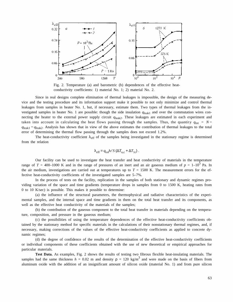
Results and Discussion. Along with the determination of concrete values of the effective heat conductivity, itis interesting to estimate the degree of correspondence of the data obtained for the investigated samples to the modelof the optically thick layer, as well to compare them with the analogous data obtained by other authors. Figure 3shows the experimental dependences λeff = f(T3) obtained for a series of heat-insulating materials in vacuum. This se-ries includes the above materials No. 1 and No. 2 (plots 2 and 1, respectively), as well as the Saffil material basedon aluminum oxide (Al2O3) fibers with different densities ρ = 96, 48, and 24 kg/m3 (plots 3, 6, 8, respectively), theQ-fiber felt material made from fibers based on silicon oxide (SiO2) with densities ρ = 96 and 48 kg/m3 (plots 4, 7,respectively), and the Cerachrome material made from a mixture of aluminum oxide and silicon oxide fibers with den-sities ρ = 192.96 kg/m3 (plots 5, 9) [8]. In considering the results presented, it can be noted that the dependencesλeff = f(T3) for all the samples presented are close to linear ones and, consequently, the radiation heat transfer in themcorresponds to the optically thick layer model.
The role of the contact-conductive heat transfer is more appreciable in the region of moderate and low tem-peratures (T > 600 K) and depends on the material density.
Fig. 3. Temperature dependences of the effective heat-conductivity coefficientsof fibrous materials to the third power.
64

It should be noted that for the regime of the optically thick layer to reach a steady state, it is necessary thatnot only the relation τ >> 1 be observed, but also the smallness of the temperature gradient in the sample at which thehypothesis on local thermodynamic equilibrium is fulfilled be ensured. The use of expressions (1) and (2) in the caseof high rates of heating or large temperature gradients is improper. Thus, Fig. 4 gives a comparison of the temperaturedependences of the heat-conductivity coefficient of material Nos. 1 and 2 obtained on the above-considered facility(curves 1 and 3) and the data determined from the solution of the two-dimensional inverse heat-conduction problem inprocessing the results of the experimental studies conducted on the "Uran-1" radiation heating device at the Heat andMass Transfer Institute of the NAS of Belarus (curves 2 and 4) (see, e.g., [14]). On this device the nonstationary re-gime of heating a sample with a high rate (40–50 K/sec) is realized. At such rates of heating, the thickness of thematerial heated to a high temperature is comparatively small and the radiation field in the sample is essentially inho-mogeneous; therefore, the regime of the optically thick layer does not reach the steady state. The results of mathemati-cal modeling of the process of radiation-conductive heat exchange for nonstationary processes point to a decrease inthe contribution of the radiation component to the total heat transfer compared to the stationary regime of heat ex-change. Precisely this fact explains the wide difference between the data on the effective heat-conductivity coefficient(especially in the region of high temperatures) obtained on different facilities. These results definitively point to thenecessity of determining the effective heat-conductivity coefficient under conditions made maximally realistic in termsof service conditions, in the first place, as to the temperature level, the rate of heating, and the characteristic dimen-sions of the sample.
Figure 5 shows the temperature dependences of the gaseous component (λg) for material Nos. 1 and 2 (plots3 and 6, respectively), the Saffil material with densities ρ = 24, 48, and 96 kg/m3 (plots 7, 2, and 1, respectively), theQ-fiber felt material with a density ρ = 48 kg/m3 (plot 5), the Cerachrome material with a density ρ = 96 kg/m3 (plot8), and the heat-conductivity coefficient of air (plot 4) at atmospheric pressure. The value of λg is equal to the differ-ence of the λeff values obtained for the corresponding material at atmospheric pressure of the gaseous medium and invacuum at equal temperatures. It is known [5, 7] that the value of λg depends on the heat conductivity of the gas, theaccommodation coefficient of the gas molecules with respect to the solid phase of the porous material, and the Knud-sen parameter, equal to the ratio of the mean free path of the gas molecules to the characteristic size of the pores inthe material. At the above densities of the materials the gas molecular flow can be considered as a continuous me-dium. If the accommodation coefficient is taken to be equal to 1, then the value of λg becomes close to the heat con-ductivity of the gas. In considering the data presented in Fig. 5, it can be seen that for most of the materials, inparticular, material Nos. 1 and 2, investigated in the present work, such an assumption is fulfilled.
The deviations of the values of λg from the heat-conductivity coefficients of air at equal temperatures arewithin the measurement errors of the effective heat-conductivity coefficients of the materials. The maximum deviations
Fig. 4. Temperature dependences of the effective heat-conductivity coefficientof fibrous materials obtained for the regimes of stationary (1, 3) and nonsta-tionary (2, 4) heat exchange.
Fig. 5. Gaseous component of the effective heat-conductivity coefficient of fi-brous materials in the air medium at atmospheric pressure.
65
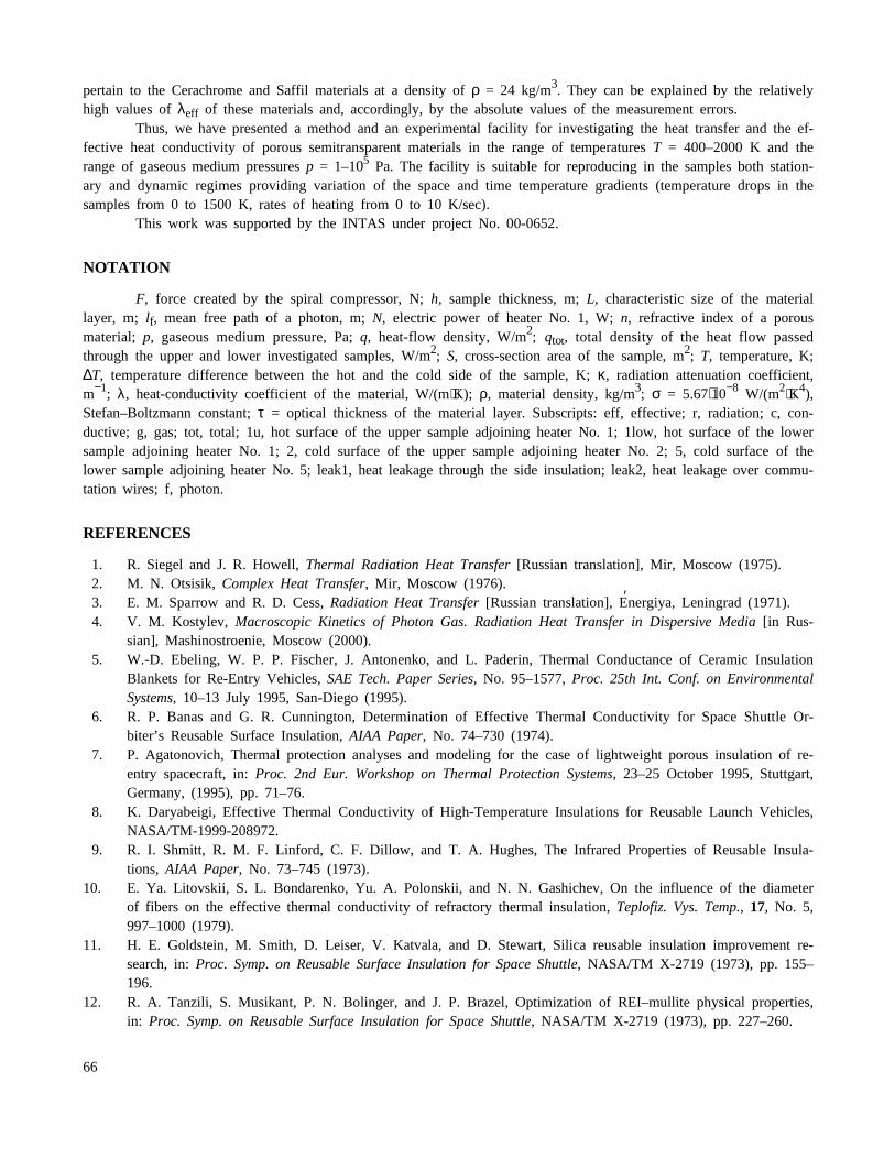
pertain to the Cerachrome and Saffil materials at a density of ρ = 24 kg/m3. They can be explained by the relativelyhigh values of λeff of these materials and, accordingly, by the absolute values of the measurement errors.
Thus, we have presented a method and an experimental facility for investigating the heat transfer and the ef-fective heat conductivity of porous semitransparent materials in the range of temperatures T = 400–2000 K and therange of gaseous medium pressures p = 1–105 Pa. The facility is suitable for reproducing in the samples both station-ary and dynamic regimes providing variation of the space and time temperature gradients (temperature drops in thesamples from 0 to 1500 K, rates of heating from 0 to 10 K/sec).
This work was supported by the INTAS under project No. 00-0652.
NOTATION
F, force created by the spiral compressor, N; h, sample thickness, m; L, characteristic size of the materiallayer, m; lf, mean free path of a photon, m; N, electric power of heater No. 1, W; n, refractive index of a porousmaterial; p, gaseous medium pressure, Pa; q, heat-flow density, W/m2; qtot, total density of the heat flow passedthrough the upper and lower investigated samples, W/m2; S, cross-section area of the sample, m2; T, temperature, K;∆T, temperature difference between the hot and the cold side of the sample, K; κ, radiation attenuation coefficient,m−1; λ, heat-conductivity coefficient of the material, W/(m⋅K); ρ, material density, kg/m3; σ = 5.67⋅10−8 W/(m2⋅K4),Stefan–Boltzmann constant; τ = optical thickness of the material layer. Subscripts: eff, effective; r, radiation; c, con-ductive; g, gas; tot, total; 1u, hot surface of the upper sample adjoining heater No. 1; 1low, hot surface of the lowersample adjoining heater No. 1; 2, cold surface of the upper sample adjoining heater No. 2; 5, cold surface of thelower sample adjoining heater No. 5; leak1, heat leakage through the side insulation; leak2, heat leakage over commu-tation wires; f, photon.
REFERENCES
1. R. Siegel and J. R. Howell, Thermal Radiation Heat Transfer [Russian translation], Mir, Moscow (1975).2. M. N. Otsisik, Complex Heat Transfer, Mir, Moscow (1976).3. E. M. Sparrow and R. D. Cess, Radiation Heat Transfer [Russian translation], E′nergiya, Leningrad (1971).4. V. M. Kostylev, Macroscopic Kinetics of Photon Gas. Radiation Heat Transfer in Dispersive Media [in Rus-
sian], Mashinostroenie, Moscow (2000).5. W.-D. Ebeling, W. P. P. Fischer, J. Antonenko, and L. Paderin, Thermal Conductance of Ceramic Insulation
Blankets for Re-Entry Vehicles, SAE Tech. Paper Series, No. 95–1577, Proc. 25th Int. Conf. on EnvironmentalSystems, 10–13 July 1995, San-Diego (1995).
6. R. P. Banas and G. R. Cunnington, Determination of Effective Thermal Conductivity for Space Shuttle Or-biter’s Reusable Surface Insulation, AIAA Paper, No. 74–730 (1974).
7. P. Agatonovich, Thermal protection analyses and modeling for the case of lightweight porous insulation of re-entry spacecraft, in: Proc. 2nd Eur. Workshop on Thermal Protection Systems, 23–25 October 1995, Stuttgart,Germany, (1995), pp. 71–76.
8. K. Daryabeigi, Effective Thermal Conductivity of High-Temperature Insulations for Reusable Launch Vehicles,NASA/TM-1999-208972.
9. R. I. Shmitt, R. M. F. Linford, C. F. Dillow, and T. A. Hughes, The Infrared Properties of Reusable Insula-tions, AIAA Paper, No. 73–745 (1973).
10. E. Ya. Litovskii, S. L. Bondarenko, Yu. A. Polonskii, and N. N. Gashichev, On the influence of the diameterof fibers on the effective thermal conductivity of refractory thermal insulation, Teplofiz. Vys. Temp., 17, No. 5,997–1000 (1979).
11. H. E. Goldstein, M. Smith, D. Leiser, V. Katvala, and D. Stewart, Silica reusable insulation improvement re-search, in: Proc. Symp. on Reusable Surface Insulation for Space Shuttle, NASA/TM X-2719 (1973), pp. 155–196.
12. R. A. Tanzili, S. Musikant, P. N. Bolinger, and J. P. Brazel, Optimization of REI–mullite physical properties,in: Proc. Symp. on Reusable Surface Insulation for Space Shuttle, NASA/TM X-2719 (1973), pp. 227–260.
66

13. A. P. Ivanov, V. A. Loiko, and V. P. Dik, Propagation of Light in Close-Packed Dispersive Media [in Rus-sian], Nauka i Tekhnika, Minsk (1988).
14. S. V. Reznik, P. V. Prosuntsov, V. P. P. Fisher, M. L. German, P. S. Grinchuk, A. M. Mikhalev, A. N. Ozno-bishin, N. V. Pavlyukevich, V. V. Toropov, M. S. Tret’yak, and A. V. Shulyakovskii, Study of the effectivethermal conductivity of heat-shield porous materials on the basis of solution of a two-dimensional inverse heat-conduction problem, in: Proc. IV Minsk Int. Forum "Heat and Mass Transfer–MIF-2004" [in Russian], Vol. 2,24–28 May 2004, Minsk (2004), pp. 244–245. (URL: http://www.itmo.by/forum/mif5/S07/7–36.PDF).
67