experimental study of rc building structures with ... study of rc building structures with...
TRANSCRIPT
ARTICLE IN PRESS
Engineering Structures( ) –www.elsevier.com/locate/engstruct
Experimental study of RC building structures with supplemental viscousdampers and lightly reinforced walls
Jenn-Shin Hwanga,b,∗, Chun-Hsiang Tsaic, Shiang-Jung Wangd, Yin-Nan Huange,b
aNational Taiwan University of Science and Technology, P.O.Box 90-130, Taipei, Taiwanb National Center for Research on Earthquake Engineering of Taiwan, Taiwan
c National Taiwan University of Science and Technology, Taiwand National Center for Research on Earthquake Engineering of Taiwan, 200, Section 3, Sin-Hai Road, Taipei, Taiwan
eDepartment of Civil, Structure and Environmental Engineering, State University of New York at Buffalo, Amherst, Buffalo, NY 14260, United States
Received 21 September 2005; received in revised form 3 March 2006; accepted 6 March 2006
Abstract
The paper presents the results of an experimental evaluation on the effectiveness of applying viscous dampers to reinforced concrete moment-resisting building structures. The unique feature of these moment-resisting concrete building structures, as is common practice in Taiwan, isthat lightly reinforced concrete exterior walls and interior partition walls are provided in construction but not considered for their contributionof stiffness and strength in the design process. With these additional walls it is suspected that, with the small relative story displacement andvelocity, the effectiveness of supplemental dampers will be very limited. However, the test results show that an efficient installation mechanism,the toggle-brace-damper system, is effective even with a small relative story drift in the seismic response control of the structure. In addition,on contrast to the usually assumed behavior, the slender wall system subjected to lateral seismic force reveals a double-curvature behavior ineach story rather than a cantilever behavior as a whole. Furthermore, for energy consideration, the “momentary input energy method” is found tobe more rational than the “absolute input energy method” to evaluate the damage potential to structures and to demonstrate the effectiveness ofsupplemental viscous dampers to structures.c© 2006 Elsevier Ltd. All rights reserved.
Keywords: Viscous dampers; Reinforced concrete; Toggle brace; Seismic response; Shaking table test; Passive control
1. Introduction
Reinforced concrete moment resisting structures accordingto their definition are normallywithout reinforced concretewalls. However, it is the common practice in Taiwan that agreat amount of reinforced concrete moment-resisting buildingsare constructed with 15 cm thick lightly reinforced concreteexterior walls together with 12 cm thick lightly reinforcedinterior partition walls. These reinforced concrete walls arenormally providedwith the minimum reinforcement requiredby the American Concrete Institute (ACI) building code [1],and are not considered for their contribution of stiffnessand strength to the structure during the design stage. As
∗ Corresponding author at: National Taiwan University of Science andTechnology, P.O.Box 90-130, Taipei, Taiwan.
E-mail address: [email protected](J.-S. Hwang).
a consequence, these reinforced concrete moment-resistingstructures are neither a pure moment resisting frame nor adual system. Therefore, no clear design guidelines are readilyavailable for the seismic design of this type of structure inthe current seismic design code [2–4]. However, it is notthe function of this study to investigate the inelastic seismicbehavior of these structures or to possibly develop rationalresponse modification factors for these structures. Instead, itis the goal to investigate the effectiveness of incorporatingsupplemental dampers into these structures. For incorporatingstructural dampers, it is recognized that with the additionalexterior and interior lightly reinforced concrete walls theeffectiveness of adding yielding type dampers will be verylimited. This is becausethe story drift is greatly reduced by theadditional walls such that the yielding type dampers can hardlybecome engaged into the energy dissipation under such a smallstory drift. Therefore, velocity type dampers, such as viscous
0141-0296/$ - see front matterc© 2006 Elsevier Ltd. All rights reserved.doi:10.1016/j.engstruct.2006.03.012

ARTICLE IN PRESS2 J.-S. Hwang et al. / Engineering Structures ( ) –
Fig. 1. Commonly used configurations for installation of viscous dampers: (a)diagonal-brace damper; (b) K-brace-damper; (c) upper toggle-brace-damper;(d) lower toggle-brace-damper.
dampers, rather than yielding type dampers have been appliedto this type of structure in Taiwan. However, with the smallstory drift, it is still not sufficiently clear how effectively thesupplemental viscous dampers will benefit this type of structurefor seismic protection. It is therefore one of the purposes ofthis study to experimentally investigate the effectiveness of aviscous damper installation scheme in reducing the seismicresponses of this type of structure.
For the installation of viscous dampers, there exist fourcommonly used configurations, the diagonal-brace damper, K-brace-damper, upper toggle-brace-damper and lower toggle-brace-damper, as shown inFig. 1 [5]. Among these installationconfigurations, the upper toggle-brace-damper system [6,7]possesses the largest amplification factor for the axial damperdisplacement corresponding toa lateral story drift of thestructure. Since it can be expected that the structure with“additional” lightly reinforced concrete walls will yield arelatively smaller lateral story drift, it is therefore decided inthis study to adopt the upper toggle-brace-damper system asthe energy dissipation system for a scaled-down three storyreinforced concrete model. Shaking table tests are conducted toinvestigate the effectiveness of the toggle-brace-damper systemby comparing the seismic responses and damage patterns oftwo test structures respectively with and without upper toggle-brace-dampers. In addition, the input energies are determinedbased on the absolute input energy [8] and the momentary inputenergy [9,10] respectively. The results are used to justify therationality of the two energy methods in evaluating the damagepotential of earthquake ground motions to structures.
2. Design formulas for structures with nonlinear toggle-brace-dampers
The force–velocity relationship of a viscous damper isdescribed by
Fd = Cd |u̇|αsgn(u̇) (1)
whereFd is the damper force,Cd is the damping coefficient,u̇ is the relative velocity between the two ends of the damper;α is the damping exponent; and sgn(u̇) = 1 whenu̇ ≥ 0 andsgn(u̇) = −1 whenu̇ < 0. The damper withα = 1 is called alinear viscous damper while the damper withα smaller than 1is called a nonlinearviscous damper.
Following the concept of equivalent damping ratio providedby Federal Emergency Management Agency [11,12] and theformulations given in research reports [5,13], the compositedamping ratio of a building structure with supplemental viscousdampers is determined based on the fundamental dynamicproperties of the first vibration mode in the form of
ξeff = ξ0 + ξd = ξ0 +
∑j
C jλ j T 2−α j ( f j φr j )1+α j Aα j −1
(2π)3−α j∑
imiφ
2i
(2)
where ξeff = the composite damping ratio of the structure;ξ0 = the inherent viscous damping ratio of the structure;ξd = the damping ratio contributed by the viscous dampersto the structure;C j = the damping coefficient of damper j ;α j = the damping exponent of damperj ; T = the naturalperiod of the first vibration mode;φi = the normalized modaldisplacement at thei th story corresponding to the first vibrationmode shape (the roof displacement is normalized to a unitvalue);A = the relative displacement of the roof to the ground;φr j = the relative modal displacement between the ends ofdamperj in the horizontal direction corresponding to the firstvibration mode shape;f j = the magnification factor of the axialdeformation of damperj to the corresponding horizontal storydrift; mi = the mass of thei th story.In practical applications,the same damping exponent is usually designed for all dampersto be installed to a building structure. The parameterλ j is thencalculated by
λ j = 22+α jΓ 2
(1 + α j
2
)Γ (2 + α j )
(3)
whereΓ is the gamma function. The magnification factors ofEq.(2) are defined by
ud = f u (4)
where ud = axial deformation of the damper andu = thehorizontal story drift; the magnification factors correspondingto the lower and upper toggle-brace-damper systems shown inFig. 1are respectively derived as [7]
fL = sinθ2 sin(θ1 + θ3)
cos(θ1 + θ2)(5)
and
fU = sinθ2
cos(θ1 + θ2)cos(θ4 − θ1) + sinθ4. (6)
Based on Eqs.(5) and(6), it can be easily understood that ifan appropriate geometric layout is selected the magnificationfactors of toggle-brace-damper systems can be much largerthan the diagonal-brace-damperand K-brace-damper systems.

ARTICLE IN PRESSJ.-S. Hwang et al. / Engineering Structures ( ) – 3
Fig. 2. Plan and elevation of test schedule with lightly reinforced concrete wall (unit: cm).
In addition, it has been demonstrated that the upper toggle-brace-damper system is more efficient than the lower toggle-brace-damper system in amplifying the axial deformation of thedamper corresponding to a prescribed story drift [7]. Therefore,the upper toggle-brace-damper system is adopted in this studyas the installation scheme of the dampers to the test structuresuch that the effectiveness of the dampers can be possiblyenhanced considering the small story drift of the test structurewith a lightly reinforced concrete wall.
3. Test structures
Two identical test structures were fabricated for shakingtable tests. One was equipped with the upper toggle-brace-damper while the other was without the dampers. The teststructure in the direction of shaking (X direction) is composedof three parallel three-story reinforced concrete frames, inwhich two exterior frames are moment resisting frames andone interior frame is a moment resisting frame with a lightlyreinforced concrete wall in one of the two bays, as shown inFig. 2. The elevation and plan dimensions of the test frameare also given inFig. 2. The teststructures are assumed tobe a 1/2.5 scaled down model. The column cross section is18 cm× 18 cm and the detailed reinforcements are shownin Fig. 3. The cross section dimensions of all girders are12 cm× 18 cm and some typical reinforcement details are
given in Fig. 3. The thickness of the concrete wall of the testmodel is 4 cm, and the reinforcement is 10 cm× 10 cmsteel welded wire mesh with a wire diameter of 4 mm, asshown inFig. 3. The horizontal reinforcement ratio is about0.3% in agreement with the common construction practicein Taiwan with a reinforcement ratio of 0.25%∼0.4% whichsatisfies the minimum requirement of ACI [1] on thehorizontalreinforcement ratio of a reinforced concrete wall. In order toenhance the workability for the casting of the 4 cm thickreinforced concrete wall, ready-mixed self compacting concreteis used. The height to width ratio(hw/ lw) of the wall isequal to 4.0 such that it is categorized as a slender wall forwhich a flexural failure mode is assumed. The average concretestrengths for the first, second and third stories are respectively2940 N/cm2, 4900 N/cm2 and 4212 N/cm2. The average testedyielding stresses for #2 (stirrups of beams and columns, andmain reinforcements of floor slabs), #3 (main reinforcementsof beams and columns), #4 (main reinforcements of footing),and 4 mm diameter wire (main reinforcements of walls) arerespectively equal to 53.6 kN/cm2, 37.4 kN/cm2, 37.1 kN/cm2
and 78.0 kN/cm2. The seismic reactive weights in the secondfloor, third floor and roof are estimated to be respectively equalto 155 kN, 155 kN and 129 kN simulated by added lead blockstogether with the reinforced concrete slabs and girders. Thedesign base shear force is determined to be equal to 0.11 W
ARTICLE IN PRESS4 J.-S. Hwang et al. / Engineering Structures ( ) –
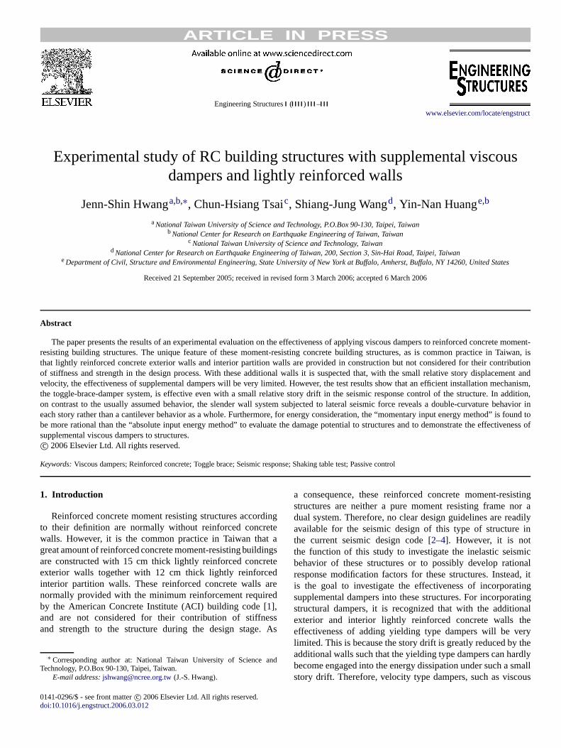
Fig. 3. Member dimensions and details of test structure.
Fig. 4. Elevation of frame B of test structure with upper toggle-brace-dampers.
according to the seismic design code of building structures ofTaiwan [4], whereW is the total seismic reactive weight of thetest structure. It should be noted that the contribution by thelightly reinforced concrete wall to the stiffness and strength ofthe test structure is not considered during the design, accordingto current practice in Taiwan. Inother words, the test structure isdesigned assuming it is a pure moment resisting structure ratherthan adual system.
The viscous dampers are installed to the interior framewith an upper toggle brace mechanism, as shown inFig. 4,to enhance the energy dissipation capability considering thepresence of the additional lightly reinforced concrete wallwhich will limit the story drift during earthquake excitation.The dynamic cyclic loading tests of the dampers have beenperformed to determine the damping coefficient and dampingexponent of the nonlinear viscous damper installed at each
Fig. 5. Typical hysteretic curves from cyclic loading tests of viscous dampers.
story. The damping exponentsα j of the viscous dampers at thefirst, second and third floors are respectively equal to 0.5, 0.4,and 0.4 while the damping coefficients,C j , are correspondinglyequal to 1.204 kN (s/mm)0.5, 2.117 kN (s/mm)0.4 and2.027 kN(s/mm)0.4. The results of typical cyclic loading testsof the viscous dampers are shown inFig. 5. A trial whitenoise shaking table test of the structure without dampers wasconducted first to identify the fundamental properties of thetest structure so that the damping contribution of the damperscan be estimated. The first mode natural period was 0.24 sand the corresponding modal displacements at first, second andthird story were 1.0, 0.73 and 0.38, respectively. Substitutingthese preliminary test results, the damper properties and theparameters given in the installation layout ofFig. 4 into Eqs.(2) and(6), the theoretical added damping ratio of the toggle-brace-dampers is illustrated inFig. 6. From the figure, it isobvious that the damping ratio contributed by the supplementaldampers is dependent on the roofdisplacement of the structure.However, it is worth noting that the fundamental dynamicproperties such as natural period and mode shape may beslightly changed after the dampers are added to the structure [7].

ARTICLE IN PRESSJ.-S. Hwang et al. / Engineering Structures ( ) – 5
Table 1Test program
Test name Ground motions Nominal PGA(cm/s2)
WN1 White noise 20100% TCU078EW EW component TCU078 station, 1999 Chi-Chi 439200% TCU078EW EW component TCU078 station, 1999 Chi-Chi 879300% TCU078EW EW component TCU078 station, 1999 Chi-Chi 1319WN2 White noise 20
Table 2Summary of maximum responses of test structure under various intensities of excitation
Excitation Frame type Max relative displacement at roof (mm) Max absolute acceleration at roof(g)
100% TCU078EWWithout dampers 15.14 0.83With dampers 9.29 0.74
200% TCU078EWWithout dampers 32.24 1.37With dampers 17.15 1.09
300% TCU078EWWithout dampers 45.85 1.60With dampers 25.66 1.29
Fig. 6. Calculated added damping ratio contributed by viscous dampers.
Therefore, the added damping ratio may not be exactly thesame aswhatFig. 6predicts. Nevertheless,Fig. 6has provideda useful reference for the preliminary design of the dampers inan iteration process.
4. Test program and test results
The two test structures, one with dampers and the otherwithout dampers are subjected to a series of white noise testsand earthquake tests, as shown inTable 1. All the groundmotions are subjected to a time scale of 1/
√2.5 corresponding
to the assumption of the test structure as a 0.4 scaled downmodel. The white noise test of the structure without addeddamper has shown a first mode damping ratio of about 7.6%.The white noise tests conducted between each two consecutiveearthquake tests are to identify the changes on the naturalfrequencies and mode shapes of the test structures. A typicalexample at the very beginning of the tests is shown inFig. 7 from which it is seen that the structure with toggle-brace-damper system has a slightly higher frequency than thestructure without a damper. It is due to the fact that thegaps existing in theswivel joints of the dampers may slip
Fig. 7. Comparison of transfer functions of test structures with and withoutdampers subjected to 0.02g PGA white noiseexcitation.
during the structure shaking such that the dampers are visco-elastic-like rather than purely viscous [7]. Another reason maybe because the connecting steel braces are insufficiently stiffcomparing with the story stiffness such that the toggle-brace-damper systems reveal a slight visco-elastic behavior ratherthan a purely viscous behavior [14].
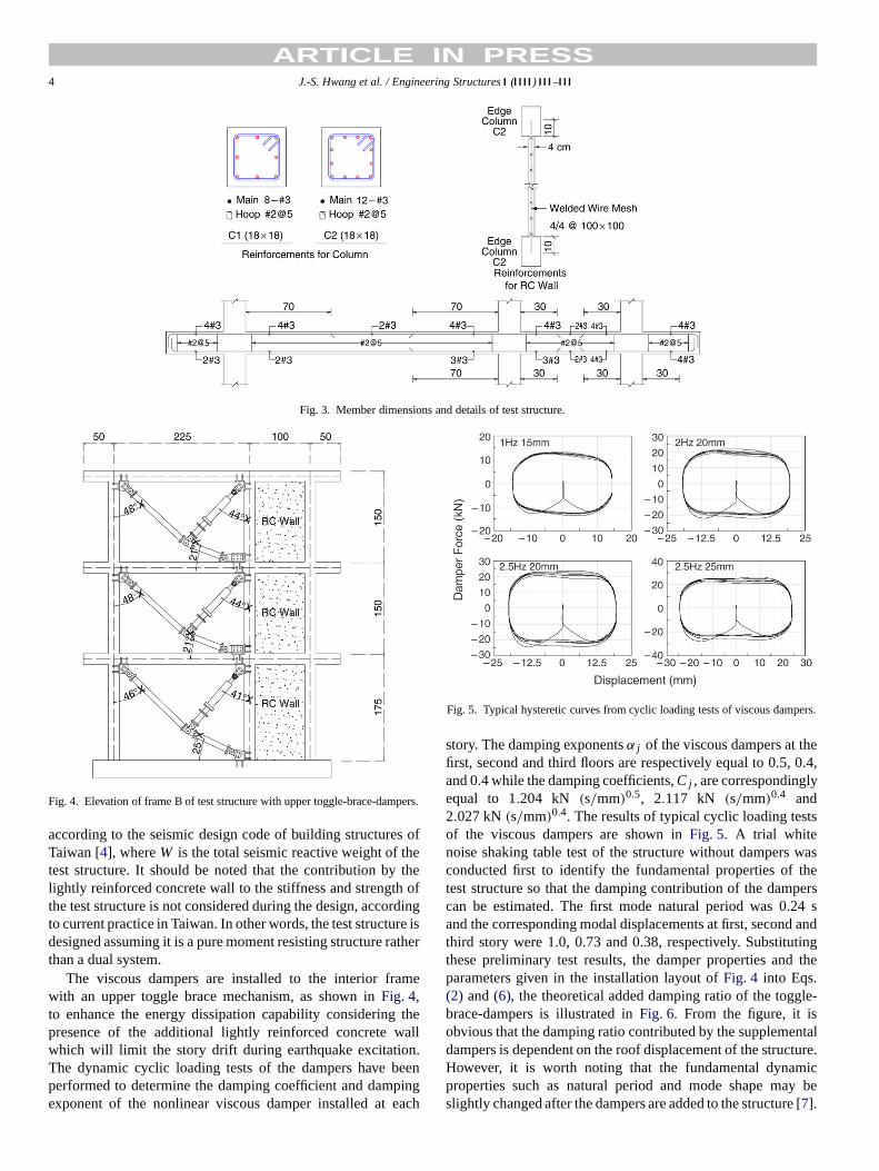
The maximum responses measured at the roof of thetwo test structures under various intensities of excitation aresummarized inTable 2from which it is seen that the dampersare effective in reducing the seismic responses of the teststructure. However, the control on the displacement responsesis more efficient than the control on the acceleration responses.Among those, for the test with the excitation of the 300% E–Wcomponent of the TCU078 station of the 1999 Taiwan Chi-Chiearthquake (denoted as TCU078EW), the damage patterns ofthe two test structures are summarized inFig. 8 from whichit can be realized that the toggle-brace-dampers can help thestructure to minimize the structural damage even though thestory drift of the test structure is very small due to the existenceof the lightly reinforced concrete wall. In addition, from thedamage pattern of the wall of the test structure without dampers,it is seen that the slender wall of the teststructure does notdeform in a cantilever shape as a whole. Instead, the wall
ARTICLE IN PRESS6 J.-S. Hwang et al. / Engineering Structures ( ) –
(a) w/o dampers.
(b) With dampers.
Fig. 8. Damage patterns of test structures subjected to 300% TCU078EW earthquake (a) without toggle-brace-damper system; (b) with toggle-brace-damper system.
elements in each story deform in a double-curvature mannerwhich is different than what has been assumed or impliedin most seismic design codes. The “clamping” effect of theconcrete slab of each story on the wall has to be consideredin the wall behavior in resisting the lateral seismic force. Alsoshown in Fig. 8, as other evidence for the double-curvaturedeformation of the wall element in each story, the damagepattern of the wall in the first story of the test structure withoutdampers under 300% TCU078EW earthquake shows that theupper part of the wall has suffered more severe damage thanthat of the lower part of the wall. This is because the wall isdeformed in a double-curvature mode, and the concrete waspoured from the top of the wall such that more aggregates werelocated in the lower part of the wall. Thus, the strength at theupper part of the wall in the first story is lower than the strengthat the lower part of the wall.
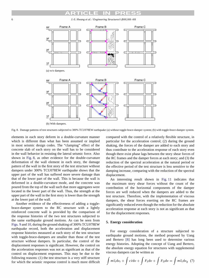
Another evidence of the effectiveness of adding a toggle-brace-damper system to the RC structure with a lightlyreinforced concretewall is provided by the comparison ofthe response histories of the two test structures subjected tothe same earthquake ground motions. As can be seen fromFigs. 9and10, during the ground shaking of 300% TCU078EWearthquake record, both the acceleration and displacementresponse histories measured at each story of the test structurewith toggle-brace-dampers are smaller than those of the teststructure without dampers. In particular, the control of thedisplacement responses is significant. However, the control onthe acceleration responses was not as significant as that of thecontrol on displacement responses. This may be due to thefollowing reasons: (1) the test structureis a very stiff structurefor which the seismic response control is much more difficult
compared with the control of a relatively flexible structure, inparticular for the acceleration control; (2) during the groundshaking, the forces of the damper are added to each story andthus contribute to the acceleration response of each story eventhough there exist phase lags between the story shear forces ofthe RC frames and the damper forces at each story; and (3) thereduction of the spectral acceleration at the natural period orthe effective period of the test structure is less sensitive to thedamping increase, comparing with the reduction of the spectraldisplacement.
An interesting result shown inFig. 11 indicates thatthe maximum story shear forces without the count of thecontribution of the horizontal components of the damperforces are well reduced when the dampers are added to thetest structure. Therefore, with the implementation of viscousdampers, the shear forces exerting on the RC frames aresignificantly reduced even though the reduction for the absoluteacceleration response at each story is not as significant as thatfor the displacement responses.
5. Energy consideration
For energy consideration of a structure subjected toearthquake ground motions, the method proposed by Uangand Bertero [8] has long been used to determine variousenergy histories. Adopting the concept of Uang and Bertero,the absolute energy equation for structures with supplementalviscous dampers can be written as∫
mv̈tdvt +∫
cv̇dv +∫
FSdv +∫
FDdv =∫
mv̈t dvg (7)
ARTICLE IN PRESSJ.-S. Hwang et al. / Engineering Structures ( ) – 7
Fig. 9. Comparison of time histories of absolute acceleration of test structureswith and without dampers subjected to 300% TCU078EW earthquake.
where the system parameters are denoted asm = mass;c = viscous damping coefficient;̈vt = absolute acceleration;vt = absolute displacement;̇v = relative velocity; v =relative displacement;vg = ground displacement;FS =restoring force; andFD = viscous damper force. The energyterms defined in Eq.(7) are respectively the kinetic energy,the inherent system damping energy, the absorbed energycomposed of recoverable elastic strain energy and irrecoverablehysteretic energy, the viscous damping energy attributed tosupplemental viscous dampers and the input energy by theearthquake ground motion.
The input energy histories of the 300% TCU078EWearthquake to the two test structures with and without addedviscous dampers are calculated inFig. 12. From the figure it isinteresting to note that the total input energies determined at theend of ground shaking are approximately the same for both teststructures. In addition, the input energy histories are somewhatsimilar for both test structures. These results are considered tobe not reasonable since the test structure with supplementalviscous dampers has been subjected to less damage than thetest structure without dampers, and thus the test structure withdampers should be subjected to less total energy input (orenergy demand) than that to the test structure without viscousdampers. Some other irrational results can also be found in the
Fig. 10. Comparison of time histories of relative displacement of test structureswith and without dampers subjected to 300% TCU078EW earthquake.
Fig. 11. Comparison of peak response of test structures with and withoutdampers subjected to 300% TCU078EW earthquake.
study of Seleemah and Constantinou [13] in which the structurewith added viscous dampers was subjected to the larger totalinput energy than the structure without viscous dampers. Basedon these studies, it is considered that employing the absoluteenergy equation proposed by Uang and Bertero to determinethe total energy input to the structure with supplemental viscousdampers may not be adequate. Therefore, in the following,the momentary input energy proposed by Hori et al. [9,10]

ARTICLE IN PRESS8 J.-S. Hwang et al. / Engineering Structures ( ) –
Fig. 12. Time histories of total input energy of test structures subjected to 300%TCU078EW earthquake (a) with toggle-brace-damper system; (b) withouttoggle-brace-damper system.
is employed to evaluate the energy demand on the two teststructures.
Rewriting Eq.(7) as∫mv̈t v̇t dt +
∫cv̇v̇dt +
∫kvv̇dt +
∫FDvv̇dt
=∫
mv̈t v̇gdt (8)
and taking the time derivative of Eq.(8), it is obtained
mv̈t v̇t + cv̇v̇ + kvv̇ + FD v̇ = mv̈t v̇g (9)
which is the equilibrium equation of power at any instant of theground shaking. The termmv̈t v̇g of Eq.(9) represents the inputpower to the structure by the earthquake. Instead of using theinput power, Hori et al. has proposed the concept of momentaryinput energy as an index to represent the damage potential of anearthquake ground motion to a structure. For doing so, Eq.(9)is integrated with respect to the time within a time interval of[t, t + �t]∫ t+�t
tmv̈tdvt +
∫ t+�t
tcv̇t dv +
∫ t+�t
tkvdv
+∫ t+�t
tFDdv =
∫ t+�t
tmv̈t dvg (10)
wheret and t + �t are two consecutive instants with a zeroabsolute velocity response of a structure during the groundshaking. According to the definition of the kinetic energy inEq. (7), the kinetic energy will then be equal to zero at thesetwo consecutive instants. The momentary input energy is thendefined as
�E =∫ t+�t
tmv̈t dvg (11)
Fig. 13. Sketch of energy terms.
which is illustrated inFig. 13. According to Eq.(11), themomentary input energy histories of the two test structuressubjected to 300% TCU078EW are shown inFig. 14. Theareaenclosed in each rectangle is the momentary input energy inthe corresponding time interval[t, t + �t]. From thefigure itcan be seen that the momentary input energy divided by�t tothe test structure with added dampers has been greatly reduced.Comparing the damage patterns of the two test structures, thisresult has demonstrated that the momentary energy methodis more rational than the absolute input energy method inevaluating the damage potential of an earthquake to structures.ComparingFigs. 9, 10and14, it can also be seen that the largerstructural responses always occur around the instants withlarger input momentary energies. This result further shows theappropriateness of using the momentary input energy insteadof the absolute input energy as an indication of the damagepotential of earthquake ground motions to the structures. Inaddition, the momentary input energy history also indicateswhen the structure may possibly be subjected to damage duringthe process of ground shaking.
6. Conclusions
The construction of reinforced concrete moment-resistingbuilding structures in Taiwan is commonly done with lightlyreinforced exterior walls and interior partition walls whosecontribution to the strength and stiffness of the structure areneglected in the design process. This study has disclosed thatthe toggle-brace-damper system isstill effective in controllingthe seismic responses of this type of structures even thoughtheir story drift (or relative story velocity) is relatively smallerthan the pure moment-resisting buildings without the lightlyreinforced concrete walls. Besides, the slender wall in a lowrise shear type building such as the test structure of this studydoes not deform in a cantilever mode as a whole, rather itdeforms in a double-curvature mode in each story. In addition,the momentary input energy method is proved to be superiorto the absolute input energy method in demonstrating theeffectiveness of adding viscous dampers to control the seismicresponses of structures. The momentary input energy can also

ARTICLE IN PRESSJ.-S. Hwang et al. / Engineering Structures ( ) – 9
Fig. 14. Time histories of momentary input energy of test structures subjected to 300% TCU078EW earthquake (a) without toggle-brace-damper system;(b) withtoggle-brace-damper system.
be used to identify the instants when the structures are subjectedto larger energy demand during the ground shaking.
Acknowledgement
The study was supported by the National Science Councilof Taiwan under Grant No. 92-2625-Z-011-002. This support isacknowledged.
References
[1] American Concrete Institute. Building code requirements for structuralconcrete. ACI 318; 2002.
[2] International Building Code. International Conference of BuildingOfficials. Whittier California.
[3] FEMA 368. NEHRP recommended provisions for seismic regulations fornew buildings and other structures. Washington (DC): Building SeismicSafety Council, Federal Emergency management Agency; 2001.
[4] Seismic Design Code of Building Structures. Taiwan: Department ofInterior; 2000.
[5] Hwang JS, Ho SY. Modification on design formulas of structures withviscous dampers. Report no. NCREE-04-009. Taipei (Taiwan): NationalCenter for Research on Earthquake Engineering of Taiwan; 2004.
[6] Constantinou MC, Tsopelas P, Hammel W, Sigaher AN. Togglebrace damper seismic energy dissipation systems. Journal of StructuralEngineering, ASCE 2001;127(2):105–12.
[7] Hwang JS, Huang YN, Hung YH. Analytical and experimental study oftoggle-brace-damper systems. Journal of Structural Engineering, ASCE2005;131(7):1035–43.
[8] Uang CM, Bertero VV. Use of energy as design criterion in earthquakeresistant design. Report no. EERC-88/18. Berkeley (CA): EarthquakeEngineering Research Center, University of California; 1988.
[9] Hori N, Iwasaki T, Inoue A. Damaging properties of ground motions andresponse behavior of structures based on momentary energy response.In: Twelfth world conference on earthquake engineering. Paper no. 0839;2000.
[10] Hori N, Inoue A. Damaging properties of ground motions and predictionof maximum responses of structures based on momentary energyresponse. Earthquake Engineering and Structural Dynamics 2002;32(9):1657–79.
[11] FEMA 273/274. NEHRP guidelines for the seismic rehabilitation ofbuildings. Washington (DC): Building Seismic Safety Council, FederalEmergency management Agency; 1997.
[12] FEMA 356. Prestandard and commentary for the seismic rehabilitationof buildings. Washington (DC): Building Seismic Safety Council, FederalEmergency Management Agency; 2000.
[13] Seleemah AA, Constantinou MC. Investigation of seismic response ofbuildings with linear and nonlinear fluid viscous dampers. Report no.NCEER-97-0004. New York: National Center for Earthquake EngineeringResearch, State University of New York at Buffalo; 1997.
[14] Fu Y, Kasai K. Comparative studyof frames using viscoelastic andviscous dampers. Journal of Structural Engineering, ASCE 1998;124(5):513–22.