experimental study of natural convection...
TRANSCRIPT
EXPERIMENTAL STUDY OF NATURAL CONVECTION HEAT TRANSFER IN A VERTICAL INTERNALLY FINNED TUBE
NOOR AFEEZA BINTI MOHAMAD SAZALI
Thesis submitted in fulfilment of the requirements for the award of the degree of
Bachelor of Mechanical Engineering with Automotive Engineering
Faculty of Mechanical EngineeringUNIVERSITY MALAYSIA PAHANG
November 2009

II
SUPERVISOR’S DECLARATION
I hereby declare that I have checked this project and in my opinion, this project is
adequate in terms of scope and quality for the award of the degree of Bachelor of
Mechanical Engineering with Automotive Engineering.
Signature
Name of Supervisor:
Position:
Date:
III
STUDENT’S DECLARATION
I hereby declare that the work in this project is my own except for quotations and
summaries which have been duly acknowledged. The project has not been accepted for
any degree and is not concurrently submitted for award of other degree.
Signature
Name: NOOR AFEEZA BINTI MOHAMAD SAZALI
ID Number: MH06018
Date:

IV
“To my beloved mother, father, my sister, family, and my beloved friends who give me support towards this study”
V
ACKNOWLEDGEMENT
اهللا الرحمن الرحیمبسم
I would like to express my gratefulness to Allah S.W.T for giving me strength and wisdom in my research work. In preparing this thesis, I was in contact with many people, researchers, academicians, technicians and practitioners. They all have contributed to my understanding and valuable thoughts during my research. First and foremost, I would like to express my special thanks to my supervisor, Prof.Dr.Rosli Bin Abu Bakar on also to my co-supervisor Mr.Khalaf Hamidi for their encouragement, guidance, ideas which enlighten my curiosity, suggestion, advice and friendship. I am gratefully expressing my thanks to my whole family who understand me and gave me the spirit and continuing support to finish this study. Owing to thanks to Mr.Lee Giok Chui which gives idea, guide and support me to finish up my task. Other than that Mr.Wan Azmi Bin Wan Hamzah also give hand on this project. I am grateful to my fellow collogues who also should be recognized for their moral support. Their view and tips are useful indeed, but it is not possible to list them all in this limited space.
VI
ABSTRACT
This paper present an experimental study of a vertical internally finned tubesubjected to natural convection heat transfer. All the main parameters that can significantly influence the heat transfer performance of finned tube have been examined. An experimental set-up was designed to study the heat transfer performance in the entrance region as well as in the fully-developed region. I using material called mild steel and its fins are assembly with the body of the cylinder tube internally. The length of tube was 100mm. The inner diameter of tube was 80mm and the outer diameter was 90mm. The tube contains four radial, straight, and equally distributed around the circumference of the tube. The height of the fins are 100mm and the length of the fins are 25mm. Air was used as a working fluid in the experiment. It is found that, unlike expected, the value of Nu for vertical cylinder under variables time varies with the temperature is increasing. Also it is found that the value of Nu increases as the time increases. In this experiment we I using a mild steel as a material for cylinder tube and fins. When mild steel are used and under the conditions of the current experiment no improvement were introduced by using mild steel material. To be conclusive on this result a further experimentations are needed by using aluminum for the cylinder tube material and different length of cylinder tube or its diameter and also using different variables length of fins.

VII
ABSTRAK
Projek ini menjalankan eksperimen perolakan semula jadi peminadahan haba bagi kedudukan menegak untuk tiub yang mempunyai sirip di dalam nya. Kesemua parameterutama mempengaruhi perlaksanaan pemindahan haba yang amat nyata sekali telah di selidik. Eksperimen telah di bentuk untuk mengkaji perlaksaan pemindahan haba. Saya telah menggunakan bahan jenis aloi keras untuk tiub sirip. Tiub dan sirp digabungkan bersama iaitu di dalam tiub. Panjang tiub adalah 100mm. Diameter dalam adalah 80mm dan diameter luar adalah 100mm. Tiub mengandungi empat sirip yang radial, sejajar dan dibahagikan sama sepanjang lilitan tiub. Tinggi sirip adalah 100mm dan panjang adalah 25mm. Udara digunakan sebagai bendalir dalam eksperimen ini Didapati, tidak seperti yang di jangka, nilai Nu untuk silinder tiub yang menegak di bawah pemboleh ubah masa berubah dengan suhu semakin meningkat. Didapati nilai Nu meningkat dengan kenaikan masa. Dalam eksperimen ini saya menggunakan alaoi keras untuk tiub dan sirip. Apabila menggunakan aloi keras untuk eksperimen ini tiada peningkatan diperkenalkan. Secara kesimpulan, untuk keputusan eksperimen yang akan datang memerlukan menggunakan aluminum sebagai bahan untuk tiub dan sirip. Dan juga panjang yang berlainan untuk tiub silinder atau berlainan diameter. Juga menggunakan panjang sirip yang berlainan sebagai pemboleh ubah.
VIII
TABLE OF CONTENTS
Page
SUPERVISOR’S DECLARATION II
STUDENT’S DECLARATION III
ACKNOWLEDGEMENTS V
ABSTRACT VI
ABSTRAK VII
TABLE OF CONTENTS VIII
LIST OF TABLES XI
LIST OF FIGURES XII
CHAPTER 1 INTRODUCTION
1.1 Introduction 1
1.2 Project Background 4
1.3 Problem Statement 5
1.4 Objective 5
1.5 Project Scope 6
CHAPTER 2 LITERATURE REVIEWS
2.1 Introduction 7
2.2 Natural Convection from Embedded Vertical Cylinder 7
2.3 Natural Convection from Embedded Horizontal Cylinder 9
2.4 Hydraulic and Heat Transfer Performance Internally Finned Tube 10
2.5 Convection Heat Transfer from a Cylinder without Fins 17
2.6 Laminar and Turbulent Flow 17
2.7 Internally Finned Tube 18

IX
CHAPTER 3 METHODOLOGY
3.1 Introduction 20
3.2 Flow Chart3.2.1 Flow Chart Fyp1 213.2.2 Flow Chart Fyp2 223.2.3 Flow Chart Design and Fabricate Specimen 233.2.4 Flow Chart Experiment 24
3.3 Apparatus 25
3.4 Material 25
3.5 Schematic Diagram 26
3.6 Experiment Setup and Procedure 27
CHAPTER 4 RESULTS AND DISCUSIONS
4.1 Introduction 31
4.2 Results
4.2.1 Analysis Result 314.2.2 Analysis Result by Suhil 34
4.3 Discussions4.3.1 Discussion for This Project 364.3.2 Discussion from Experiment by Suhil 38
4.3.2.1 Heat Transfer from Vertical Cylinder without PorousMaterial 39
4.3.2.2 Heat Transfer from Vertical Cylinder with Porous Fins 48
CHAPTER 5 CONCLUSION AND RECOMMENDATION
5.1 Introduction 52
5.2 Conclusion 52
5.3 Recommendation
5.3.1 Material 53
5.3.2 Experiment Setup and Apparatus 54
REFERENCES 56

X
APPENDIXES:
A Measurement of Finned Tube 62
B Finned Tube Cylinder 63
C Way to Measure Temperature 64
D Gantt Chart 65

XI
LIST OF TABLE
TABLE TITLE PAGE
Table 3.1 Apparatus and Descriptions 25
Table 3.2 The Characteristics of the Porous Material used 30
Table 4.2.1 Data for Cylinder Tube without Fins 32
Table 4.2.2 Data for Cylinder Tube with Fins 32
Table 4.2.3 Nusselt Number and Rayleigh Number for Cylinder Tube without fins 33
Table 4.2.4 Nusselt Number and Rayleigh Number for Cylinder Tube with fins 33
Table 4.2.5 Coefficient for Cylinder Tube with fins 33

XII
LIST OF FIGURES:
FIGURE TITLE PAGE
Figure 1.1 Natural Convection Scenarios 2
Figure 1.2 Dimension of Internally Finned Tube 5
Figure 2.1 Number of Fin Effect on Fraction Factor 12
Figure 2.2 Effect of Number of Fin on Friction for Shorter Fins 13
Figure 2.3 Effect of Fin Height on Friction Factor 14
Figure 2.4 Inter-fin Region Effect on Friction Factors 15
Figure 2.5 Inverse Effect of Fin Height on Nusselt Number 16
Figure 3.1 Dimensions of Material 25
Figure 3.2 Schematic Diagram 26
Figure 3.3 Experimental Determination of K and F 29
Figure 4.1 Graph Nusselt Number Vs Rayleigh Number for Cylinder Tube without fins 37
Figure 4.2 Graph Nusselt Number Vs Rayleigh Number forCylinder Tube with fins 38
Figure 4.3 Variation of Local Heat Transfer Coefficient along the Cylinder for Selected Heat Fluxes 39
Figure 4.4 Variation of Nusselt Number along the Cylinderwith the Variation of the Modified Ra at Different Locations 40
Figure 4.5 Variation of the Local Nusselt Number with the Variationof the Modified Ra in the Turbulent Region 41
Figure 4.6 Variation of the Local Nusselt Number with the Variation of the Modified Ra for all Heat Fluxes 42
Figure 4.7 Variation of Nusselt Number along the Cylinderwith the Variation of the Modified Ra at Different Locations 43
XIII
Figure 4.8 Variation of the Local Nusselt Number with theVariation of the Modified Ra in the Turbulent Region at Different Locations along the Cylinder 44
Figure 4.9 Variation of the Local Nusselt Number with the Variation of the Modified Ra at all Tested Locations along the Cylinder and for all Heat Fluxes 45
Figure 4.10 Variation of the Local Nusselt Number with the Variation of the Modified Ra in the Laminar Region at Selected Locations along the Cylinder 46
Figure 4.11 Variation of the Averaged Nu with the Variation ofRa*L for Two Cylinders 47
Figure 4.12 Comparisons between the Variations of the Nux with the Variation of Ra*x for the 80 mm Cylinder for Different Porous Layers (Porous B) 48
Figure 4.13 Variation of Surface Effectiveness with the Variation of Ra*L for the 80 mm Cylinder for Different Porous Layers Thicknesses (Porous B) 49
Figure 4.14 Fin Efficiencies for the Porous Layers Covering the 80 mm Vertical Cylinder 50
Figure 4.15 Variation of the Local Nusselt Number with the Variation of the modified Ra at all Locations for Single Short Fin 51
CHAPTER 1
INTRODUCTION
1.1 INTRODUCTION
Natural mode of heat transfer employed in many applications as a higher
pressure drop penalty. The pitch was seen to play an important role in the entrance
region. The-core region insert was shown to enhance the heat transfer much more than
the wall region insert, contrary to the earlier assumption that the core may not play as
important a role. However, the combined effect of the two regions could be different
from the individual influence of each region. The need for compact and efficient heat
transfer convection heat transfer is important equipment has stimulated research efforts
in the area of heat transfer augmentation. In order to enhance the rate of heat transfer,
finned surfaces have been applied to cooling devices for electronic equipment and
compact heat exchangers for many years.
Convection involves the transfer of heat by the motion and mixing of
“macroscopic” portions of a fluid (that is, the flow of a fluid past a solid boundary). The
term forced convection is used if this motion and mixing is caused by an outside force,
such a pump. The transfer of heat from a hot water radiator to a room is an example of
heat transfer by natural convection. The transfer of heat from the surface of a heat
exchanger is an example of forced convection.
Natural or “Buoyant” or “Free” convection is a very important mechanism that is
operative in a variety of environments from cooling electronic circuit boards in
computers to causing large scale circulation in the atmosphere as well as in lakes and
2
oceans that influences the weather. It is caused by the action of density gradients in
conjunction with a gravitational field. This is a brief introduction that will help you
understand the qualitative features of a variety of situations you might encounter.
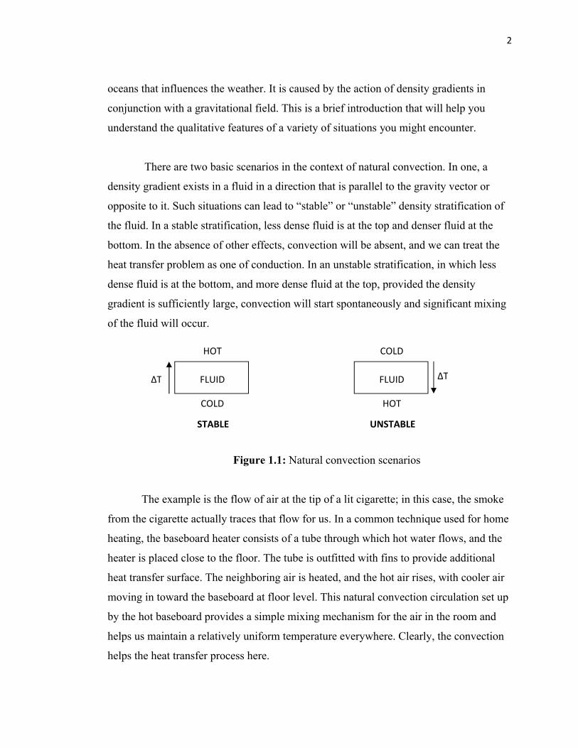
There are two basic scenarios in the context of natural convection. In one, a
density gradient exists in a fluid in a direction that is parallel to the gravity vector or
opposite to it. Such situations can lead to “stable” or “unstable” density stratification of
the fluid. In a stable stratification, less dense fluid is at the top and denser fluid at the
bottom. In the absence of other effects, convection will be absent, and we can treat the
heat transfer problem as one of conduction. In an unstable stratification, in which less
dense fluid is at the bottom, and more dense fluid at the top, provided the density
gradient is sufficiently large, convection will start spontaneously and significant mixing
of the fluid will occur.
Figure 1.1: Natural convection scenarios
The example is the flow of air at the tip of a lit cigarette; in this case, the smoke
from the cigarette actually traces that flow for us. In a common technique used for home
heating, the baseboard heater consists of a tube through which hot water flows, and the
heater is placed close to the floor. The tube is outfitted with fins to provide additional
heat transfer surface. The neighboring air is heated, and the hot air rises, with cooler air
moving in toward the baseboard at floor level. This natural convection circulation set up
by the hot baseboard provides a simple mixing mechanism for the air in the room and
helps us maintain a relatively uniform temperature everywhere. Clearly, the convection
helps the heat transfer process here.
HOT
COLD
FLUIDΔT
COLD
HOT
FLUID ΔT
UNSTABLESTABLE
3
The used of heat transfer enhancement has become widespread during the last 50
years. The goal of heat transfer enhancement is to reduce the size and cost of heat
exchanger equipment, or increase the heat duty for a give size heat exchanger. This goal
can be achieve in two ways: active and passive enhancement. Of the two, active
enhancement is less common because it requires addition of external power (e.g., an
electromagnetic field) to cause a desired flow modification. On the other hand, passive
enhancement consists of alteration to the heat transfer surface or in corporation of a
device whose presence results in a flow field modification. The most popular
enhancement is the fin.
Heat transfer by convection is more difficult to analyze than heat transfer by
conduction because no single property of the heat transfer medium, such as thermal
conductivity, can be defined to describe the mechanism. Heat transfer by convection
varies from situation to situation (upon the fluid flow conductions), and it is frequently
coupled with the mode of fluid flow. In practice, analysis of heat transfer by convection
is treated empirically (by direct observation).
Convection heat transfer is treated empirically because of the factors that affect
the stagnant film thickness:
Fluid velocity
Fluid viscosity
Heat flux
Surface roughness
Type of flow (single-phase/two-phase)
4
1.2 PROJECT BACKGROUND
Internally finned tubes have received considerable attention because of the fact
that they have been used widely in industrial applications. Internally finned tube has
found extensive use in heat exchangers. When improvement in the process of heating or
cooling is required, then better design of fin compactness and spatial geometry is very
essential. Several studies have been conducted to investigate the effect of fin
characteristics on heat transfer. Most of the relevant previous works have focused on
limited cases of the number and length of the internal fin.
The apparent advantages of fins are that they increase the heat transfer rate by
providing additional surface area. However, fins placed in a tube cause complex flow
patterns and increase flow resistance. As the number or the height of fins increases,
flow friction increases, thus requiring greater pumping power to sustain a given mass
flow rate. Therefore, to design a compact heat exchanger with internally finned tubes,
we should optimize the fin geometry by accounting for both flow friction and heat flux.
The present study was undertaken to develop new experimental data on Nusselt
number and heat transfer during laminar flow an air as a medium in internally finned
tube with vertical position. Even though there have been several numerical studies on
fluid flow and heat transfer performance of internally finned tubes, the experimental data
for thermally developing flow in internally tubes has been scarce. Therefore, the new
data expected to provide very valuable and timely addition to the finned tube.
The analysis is base on the vertical internally finned tube. During the experiment
the data taken was temperature at the surface, fins, and inside the tube.

5
1.3 PROBLEM STATEMENT
The problem to be considered is that of Natural Convection heat transfer for fully
developed flow in an internally finned tube. The fins are radial, straight and equally
distributed around the circumference of the tube as shown in Figure 1.2. The length of
the fin is fixed. The flow is subjected to a uniform heat input flux unit axial length.
Because of the symmetry the calculation domain is performed over a half sector (the
complete sector is the area between the two consecutive fins).
Figure 1.2: The dimension of internally finned tube
1.4 OBJECTIVES
The objectives of the project are to determine the effect of flow in the tube with
fins. Besides, in this project I also have to determine the heat transfer from surrounding
in the vertical position of the cylinder tube. Then I also need to find the value of the
coefficient with the given formula:
= . .
= 80= 90
a = 25
t = 3
L = 100
6
Where, I need to find ad calculate the coefficient of , .1.5 PROJECT SCOPES
i. Used air as a medium
ii. Used laminar flow
iii. Measure the temperature
iv. Measure the time to show the behavior surface temperature with time.
v. Calculate the heat transfer, Nusselt number and find the coefficient.

7
CHAPTER 2
LITERATURE REVIEW
2.1 INTRODUCTION
Internally longitudinal finned tubes are widely used in many engineering fields to
enhance heat transfer, such as power plants, chemical process and petroleum industries.
Many researchers have investigated the problem of optimizing the shape of the finned
surfaces in order to reduce the weight and the size of heat exchangers and increase heat
transfer.
2.2 NATURAL CONVECTION FROM EMBEDDED VERTICAL
CYLINDERS
Minkowycz and Cheng [1] gave an approximate solution for heat transfer in the
case of vertical cylinders embedded in porous media. The following equations describe
the problem of steady natural convection about a vertical cylinder of radius R embedded
in a saturated porous medium with a prescribed wall temperature.
( ) + ( ) = 0 (1)
= + (2)
= − (3)
8
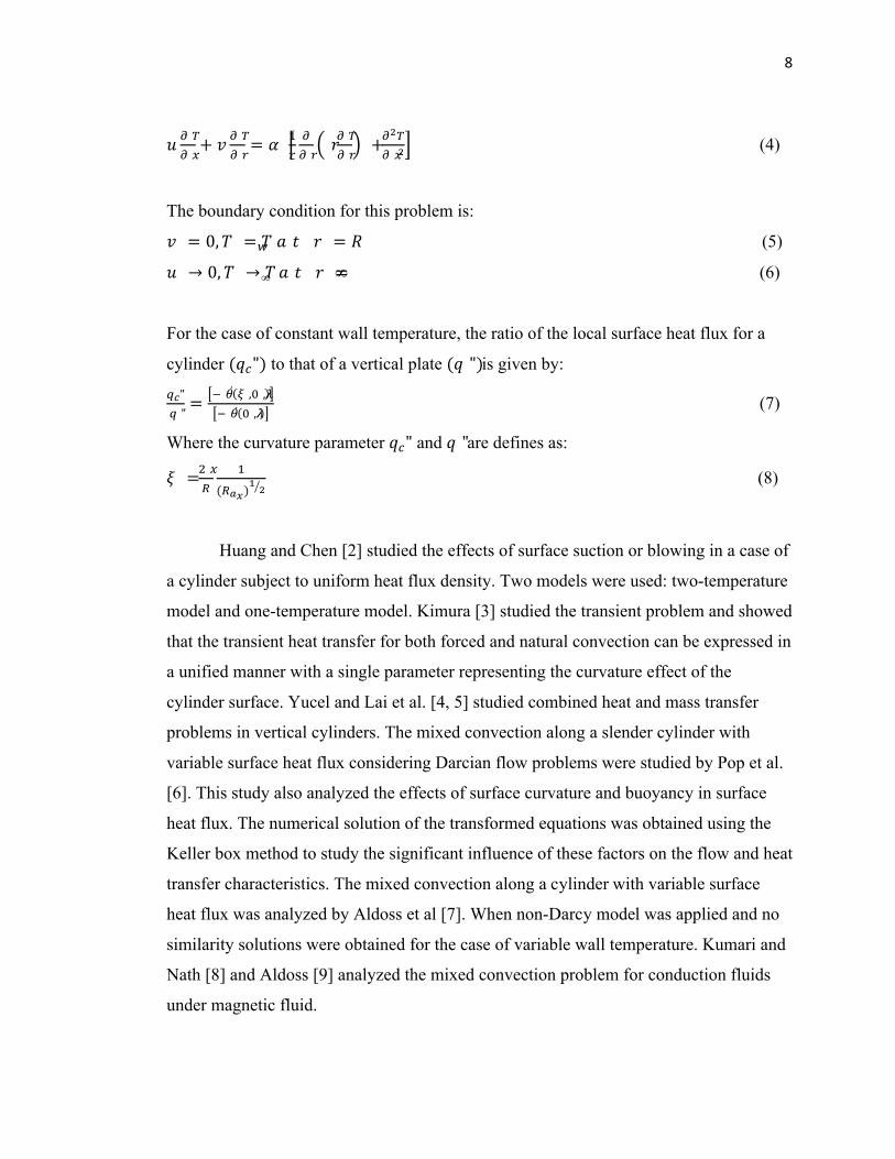
+ = + (4)
The boundary condition for this problem is:
= 0, = = (5)
→ 0, →∞ =∞ (6)
For the case of constant wall temperature, the ratio of the local surface heat flux for a
cylinder ( ") to that of a vertical plate ( ")is given by:
"" = ′( , ,)
′( , ) (7)
Where the curvature parameter " and "are defines as:
= ( ) (8)
Huang and Chen [2] studied the effects of surface suction or blowing in a case of
a cylinder subject to uniform heat flux density. Two models were used: two-temperature
model and one-temperature model. Kimura [3] studied the transient problem and showed
that the transient heat transfer for both forced and natural convection can be expressed in
a unified manner with a single parameter representing the curvature effect of the
cylinder surface. Yucel and Lai et al. [4, 5] studied combined heat and mass transfer
problems in vertical cylinders. The mixed convection along a slender cylinder with
variable surface heat flux considering Darcian flow problems were studied by Pop et al.
[6]. This study also analyzed the effects of surface curvature and buoyancy in surface
heat flux. The numerical solution of the transformed equations was obtained using the
Keller box method to study the significant influence of these factors on the flow and heat
transfer characteristics. The mixed convection along a cylinder with variable surface
heat flux was analyzed by Aldoss et al [7]. When non-Darcy model was applied and no
similarity solutions were obtained for the case of variable wall temperature. Kumari and
Nath [8] and Aldoss [9] analyzed the mixed convection problem for conduction fluids
under magnetic fluid.

9
2.3 NATURAL CONVECTION FOR EMBEDDED HORIZONTAL
CYLINDERS
Merkin [10] studied the problem of a horizontal cylinder embedded in porous
media. This is a special case of a general two-dimensional heated object that he
analyzed. For the large Rayleigh number, the heat transfer coefficient can by calculated
using:
= 0.565 (9)
Where:
== ( ∞)
= thermal diffusivity for porous media
h = average heat transfer coefficient
The results were later generalized by Chen and Chen [11] for fluids with non-
Newtonian viscosities. They extended it to power law fluids. Fand et al. [12] studied
heat transfer problems and conducted experiments in porous media packed with random
glass spheres using different fluids. This study suggested the following relationships for
different ranges of Reynolds numbers:
For 0.001 < == . = 0.618 . + 8.54 × 10 ℎ for 0.001 < 3 (10)
= . = 0.766 . ( ) . for 3 < ≤ 100 (11)
Where:
==
and are constants.
10
The problem of horizontal cylinders embedded in a semi-infinite porous media
was analyzed by Farouk and Shayer [13]. The heat transfer experiments of this problem
were done by Fernandez and Schrock [14]. Cheng [15] studied the problem of mixed
convection about a horizontal cylinder. Others, like Sano [16], Ingham et al. [17], Pop et
al. [18, 19], Tyvand [20], Sundfor and Tyvand [21] and Bradean et al. [22] used detailed
analytical and numerical analysis of transient natural convection from embedded
horizontal cylinders.
2.4 HYDRAULIC AND HEAT TRANSFER PERFORMANCE IN
INTERNALLY FINNED TUBE
The earliest works on straight internally finned tubes were experimentally done
by Vasil’chenko and Barbaritskaya [23,24]. Transformer oil was used as the test fluid
with operating conditions of 200 < < 10,000and 70 < < 140. Both laminar
and turbulent heat transfer were observed in this region. Transition Reynolds number for
tubes with different number of fins of fin height were different. Five finned tubes with
fin geometries of 4 ≤ ≤ 8and 0.26 ≤ ≤ 0.63 were included in this study which
showed 30 to 70% increases in heat transfer with the use of finned tubes compared to
smooth tubes done by Xiaoyue [25].
Watkinson et al [26, 27] tested 18 finned tubes; five had straight fins and 13 had
spiral fins. Water and air were used as test fluids with tube geometry of 6 ≤ ≤ 50,0.05 ≤ ≤ 0.30and 0° ≤ ≤ 15° with 1000 ≤ ≤ 100,000and 1.0 ≤ ≤ 3.4for water and with 10,000 ≤ ≤ 100,000and = 0.71for air. At = 50,000the
experimental results indicated that a 17 to 95% heat transfer enhancement (Nusselt
number increase) over the smooth tube for air and 15 to 85% was gained for water,
depending on different fin geometries. Spirally finned tubes showed better heat transfer
enhancement performance than straight finned tubes. Analysis confirmed that fin
efficiencies were close to 100%. Correlations developed for friction factor and Nusselt
11
numbers were strongly dependent on specific fin geometries and fluid properties used in
their experiments’ and limited to rather small helix angles.
Obot et al [26] and Obot [28,29] also has developed a method to correlate
pressure drop and heat transfer in smooth and rough passages (including finned tubes)
through the use of the critical Reynolds number for transition. Smooth tube correlations
gave results satisfactory for design calculations when the usual Reynolds number was
replaced by a reduced Reynolds number. The critical parameters at the onset transition
to turbulent flow are required to calculate this number, so a priori knowledge of
transition is needed to estimate performance using this approach. The transition
Reynolds number is another global flow characteristic variable, similar to the friction
factor, dominated by the particular tube geometries, which is connected closely with the
mechanism of turbulent flow. Therefore, it may be as difficult to predict as friction
factor itself.
More recently, Vlakanic [30] tested fifteen spirally finned tubes for obtaining the
pressure drop and heat transfer performance. The fin geometries covered 8 ≤ ≤ 54,0.015 ≤ ≤ 0.17and 0° ≤ ≤ 15°. Friction factors and Nusselt numbers were
measured in the range of 7,000 ≤ ≤ 70,000, 0.62 ≤ ≤ 1.35 and 3.5 ≤ ≤5.0 for both heating and cooling conditions. According to the experimental data obtained
with water, it was concluded that the heat transfer performance was augmented by about
20 to 200% compared to a smooth tube depending on the specific fin geometry. The
corresponding pressure drop penalty increase ranged from 40% to about 170%.
Compared with previous studies on internally finned tubes, Vlakancic’s data may
be the largest and most complete database in overall friction factors and heat transfer
performance. Because varieties of fin geometries and wide range of Reynolds numbers
were covered in the experiments, the effect of fin heights, fin width and helix angle were
extensively investigated including both “tall fins” and “micro-fins”.