experimental shear behavior of stone masonry joints
TRANSCRIPT
Structural Analysis of Historic Construction – D’Ayala & Fodde (eds)© 2008 Taylor & Francis Group, London, ISBN 978-0-415-46872-5
Experimental shear behavior of stone masonry joints
G. Vasconcelos, P.B. Lourenço & D. OliveiraIsise, Department of Civil Engineering, University of Minho, Guimarães, Portugal
ABSTRACT: The mechanical characterization of the shear strength properties takes a major role on the evalu-ation of the lateral strength of masonry shear walls by means of simplified methods or when numerical analysisbased on micromodelling approach is to be followed. Thus, the present paper presents an overview of the resultsobtained from direct shear tests of different types of masonry joints: dry and mortar masonry joints. Besides theshear strength parameters, a good insight was achieved in the evaluation of the complete shear stress-shear loaddisplacement diagrams.
1 INTRODUCTION
As reported in literature (Hamid & Drysdale 1980,Samarasinghe & Hendry 1980), the orientation of themortar joints to the applied stresses takes a major rolein the ultimate strength and failure modes of masonryunder in-plane stress state. The influence of mortarjoints acting as a plan of weakness on the compos-ite behavior of masonry is even more relevant in caseof strong unit-weak mortar joint combinations, whichare characteristic of ancient stone masonry. Two basicfailure modes can occur at the level of the unit-mortarinterface: tensile failure (mode I) associated to stressesacting normal to joints and leading to the separation ofthe interface, and shear failure (mode II) correspond-ing to a sliding mechanism of the units or shear failureof the mortar joint.
Although several experimental studies have beencarried out in the characterization of the bond shearstrength of unit-mortar interfaces (Atkinson Amadio& Rajgelj 1991, Binda et al. 1997), lesser research isavailable on the shear behavior of dry stacked masonryjoints, even if recent studies have been carried out onthe behavior of dry masonry joints submitted to cyclicloading (Lourenço & Ramos 2004). On the other hand,the features of rock joints under shear behavior canbe partly extended to dry masonry joints. The shearbehavior of rock joints has been played an impor-tant role in the scope of rock mechanics research. Inparticular, several experimental and numerical studiespointed out the role of the surface roughness on thecyclic shear behavior of natural rock joints (Lee et al.2001, Huang et al. 2002).
The relation between normal and shear stresses hasa major role in the shear behavior of masonry joints,governing its failure mode (Hamid & Drysdale 1980).
For pre-compression stresses above a certain level,the shear strength decreases and a combined shear-splitting failure or splitting of the units occur. In caseof shear failure along the joint by slipping of the unitsalong the joint, an increase of the compression normalto bed joint leads to an increase of the shear strength.As has been widely reported (Atkinson et al. 1989,Riddington & Ghazali, 1990), the shear strength ofmasonry under moderate normal stresses, for whichthe nonlinear behavior of mortar is negligible and thefriction resistance takes the central role, can be givenby the Coulomb criterion:
where c is the shear strength at zero vertical load stress(usually denoted by cohesion) and µ is the frictioncoefficient. For dry joints the cohesion is assumedto be zero. It should be kept in mind that the failureenvelop given by eq.1 describes only a local failureand can not be directly related to the shear failure ofmasonry walls submitted to in-plane horizontal loads(Mann & Müller 1982, Atkinson et al. 1989, Calviet al.1996).
In addition to the knowledge of the mechanicalproperties from masonry components, namely unitsand mortar, the analysis of masonry behavior underin-plane loading is only possible if information aboutthe local composite behavior and the interactionbetween units and mortar is available.
Therefore, the present work deals with the mechan-ical characterization of the shear behavior of dry andmortar masonry joints (cohesion, friction angle anddilatancy). In order to attain such goal, an experimen-tal program was defined, including direct shear testsconducted on dry and mortar masonry joints. Besides
771
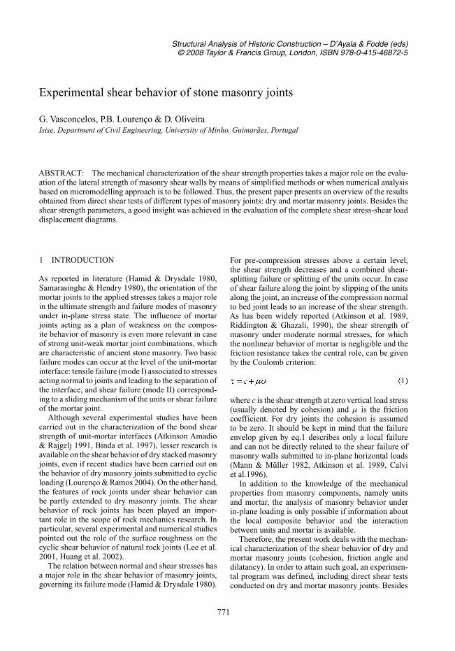
(a) (b)
Figure 1. Masonry specimens; (a) dry joints; (b) mortarjoints.
ensuring mechanical properties for numerical simula-tions of the in-plane behavior of stone masonry wallstructures, the adopted testing program provides alsothe fundamental information about the shear behaviorof two different masonry joints.
2 EXPERIMENTAL DETAILS
2.1 Test specimens and procedure
Although triplet tests have been adopted as the Euro-pean standard method (EN1052-3 2002) to performshear tests in mortar joints, the shear strength proper-ties of dry and mortar joints were obtained by meansof direct shear tests conducted on couplet specimens,see Figure 1 (Vasconcelos 2005). In fact, in the triplettest, the two joints do not fail at the same time and theanalysis of the experimental results is rather complex,Lourenço et al. (2004).
The shear tests were carried out in a servocontrolleduniversal testing machine CS7400S. This equipmentis composed by two independent hydraulic actua-tors used to transmit normal and shear loads, ableto operate under force or displacement control. Thefeatures of the testing equipment and the existingloading platens imply that the most suitable testingsample is composed by two units with geometry anddimensions indicated in Figure 1 and a single dry ormortar joint, similarly to Pluijm (1999) and Hansenet al. (1998). The surface of the dry masonry unitsadopted here is smooth resulting from sawing thespecimens, whereas the joint surface of the units ofthe mortar assemblages presents enough roughnessto achieve appropriate adherence conditions and thusmore realistic masonry can be simulated. The detailedexperimental characterization of this type of granitecan be seen inVasconcelos et al. (2007).The specimenswere placed between two thick steel plates and attachedto the steel platens by steel bolts, so that shear forcecould be transmitted. Thin steel sheets were attachedto the steel plates to concentrate the shear load as closeas possible in the bed joint, aiming at preventing bend-ing moments and provide a more uniform shear stressdistribution.
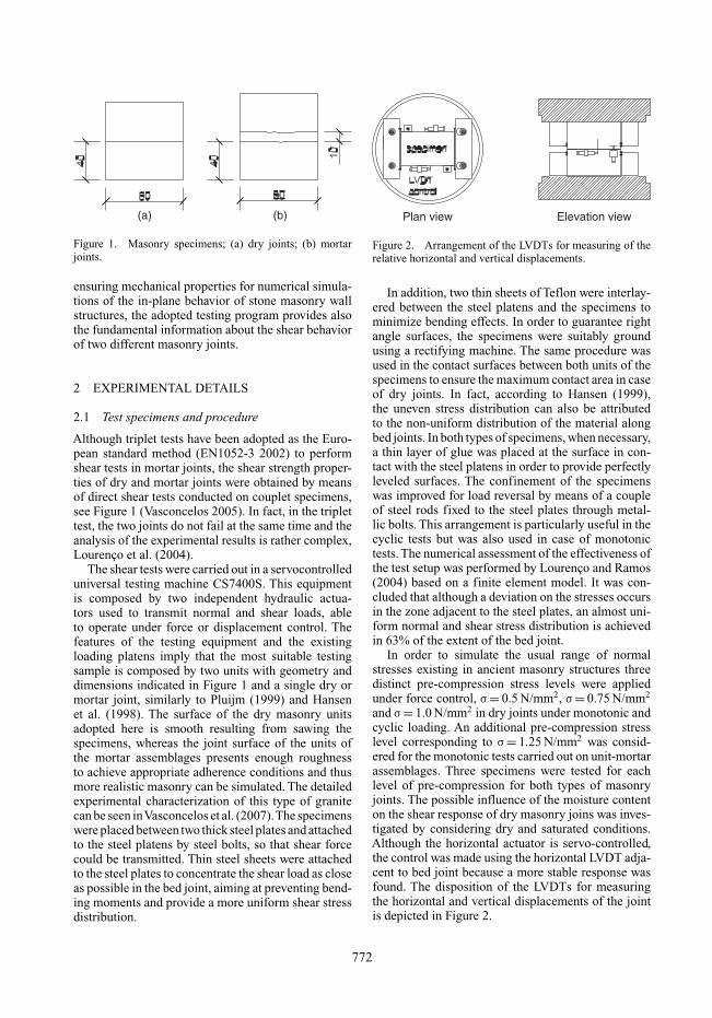
Plan view Elevation view
Figure 2. Arrangement of the LVDTs for measuring of therelative horizontal and vertical displacements.
In addition, two thin sheets of Teflon were interlay-ered between the steel platens and the specimens tominimize bending effects. In order to guarantee rightangle surfaces, the specimens were suitably groundusing a rectifying machine. The same procedure wasused in the contact surfaces between both units of thespecimens to ensure the maximum contact area in caseof dry joints. In fact, according to Hansen (1999),the uneven stress distribution can also be attributedto the non-uniform distribution of the material alongbed joints. In both types of specimens, when necessary,a thin layer of glue was placed at the surface in con-tact with the steel platens in order to provide perfectlyleveled surfaces. The confinement of the specimenswas improved for load reversal by means of a coupleof steel rods fixed to the steel plates through metal-lic bolts. This arrangement is particularly useful in thecyclic tests but was also used in case of monotonictests. The numerical assessment of the effectiveness ofthe test setup was performed by Lourenço and Ramos(2004) based on a finite element model. It was con-cluded that although a deviation on the stresses occursin the zone adjacent to the steel plates, an almost uni-form normal and shear stress distribution is achievedin 63% of the extent of the bed joint.
In order to simulate the usual range of normalstresses existing in ancient masonry structures threedistinct pre-compression stress levels were appliedunder force control, σ = 0.5 N/mm2, σ = 0.75 N/mm2
and σ = 1.0 N/mm2 in dry joints under monotonic andcyclic loading. An additional pre-compression stresslevel corresponding to σ = 1.25 N/mm2 was consid-ered for the monotonic tests carried out on unit-mortarassemblages. Three specimens were tested for eachlevel of pre-compression for both types of masonryjoints. The possible influence of the moisture contenton the shear response of dry masonry joins was inves-tigated by considering dry and saturated conditions.Although the horizontal actuator is servo-controlled,the control was made using the horizontal LVDT adja-cent to bed joint because a more stable response wasfound. The disposition of the LVDTs for measuringthe horizontal and vertical displacements of the jointis depicted in Figure 2.
772
The relative horizontal displacement of the joint wasmeasured by the horizontal LVDTs placed at each sideof the specimen. Although the LVDTs were fixed tothe unit through the supports that were glued to it,the influence of the shear deformation of the unitsshould be marginal in the measured final deformation(Hansen 1999). The vertical displacements of the jointwere measured by the LVDTs placed at the oppositecorners of the specimen. The relative vertical dis-placements were monitored in case of dry joints forassessing the possible dilatant behavior of the joints.Nevertheless, technical problems did not allow to mea-sure relative vertical displacements in mortar joints, astests were conducted in a subsequent phase. Both shearand normal stresses were measured and recorded bythe horizontal and vertical load cells of 22 kN capacity.
3 ANALYSIS OF RESULTS
3.1 Monotonic behavior of dry joints
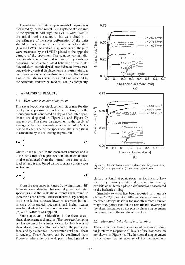
The shear load-shear displacement diagrams for dis-tinct pre-compression stress levels resulting from themonotonic tests conducted on dry and saturated spec-imens are displayed in Figure 3a and Figure 3brespectively. The shear displacement is the result ofaveraging the measurements recorded by both LVDTsplaced at each side of the specimen. The shear stressis calculated by the following expression:
where H is the load in the horizontal actuator and Ais the cross area of the joint section. The normal stressis also calculated from the normal pre-compressionload, N , and is also based on the total area of the crosssection as:
From the responses in Figure 3, no significant dif-ferences were detected between dry and saturatedspecimens and the peak shear strength was found toincrease as the normal stresses increase. By compar-ing the peak shear stresses, lower values were obtainedin case of saturated specimens and higher scatterwas found when the maximum pre-compression level(σ0 = 1.0 N/mm2) was applied.
Four stages can be identified in the shear stress-shear displacement diagrams. The pre-peak behavioris characterized by a linear extent for low levels ofshear stress, associated to the contact of the joint inter-face, and by a clear non-linear stretch until peak shearis reached. These features can be confirmed fromFigure 3, where the pre-peak part is highlighted. A
(a)
(b)
Figure 3. Shear stress-shear displacement diagrams in dryjoints; (a) dry specimens; (b) saturated specimens.
plateau is found at peak stress, as the shear behav-ior of dry masonry joints under monotonic loadingexhibits considerable plastic deformations associatedto the inelastic sliding.
Similarly to what has been reported in literature(Misra 2002, Huang et al. 2002) no shear softening wasrecorded after peak stress for smooth surfaces, unlikerough rock joints that exhibit remarkable lowering ofthe shear resistance as the plastic shear displacementincreases due to the roughness fracture.
3.2 Monotonic behavior of mortar joints
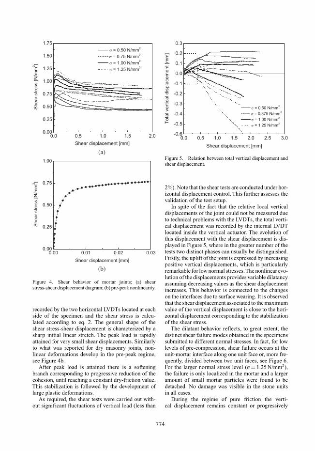
The shear stress-shear displacement diagrams of mor-tar joints with respect to all levels of pre-compressionare shown in Figure 4a. The horizontal displacementis considered as the average of the displacements
773
(a)
(b)
Figure 4. Shear behavior of mortar joints; (a) shearstress-shear displacement diagram; (b) pre-peak nonlinearity.
recorded by the two horizontal LVDTs located at eachside of the specimen and the shear stress is calcu-lated according to eq. 2. The general shape of theshear stress-shear displacement is characterized by asharp initial linear stretch. The peak load is rapidlyattained for very small shear displacements. Similarlyto what was reported for dry masonry joints, non-linear deformations develop in the pre-peak regime,see Figure 4b.
After peak load is attained there is a softeningbranch corresponding to progressive reduction of thecohesion, until reaching a constant dry-friction value.This stabilization is followed by the development oflarge plastic deformations.
As required, the shear tests were carried out with-out significant fluctuations of vertical load (less than
Figure 5. Relation between total vertical displacement andshear displacement.
2%). Note that the shear tests are conducted under hor-izontal displacement control. This further assesses thevalidation of the test setup.
In spite of the fact that the relative local verticaldisplacements of the joint could not be measured dueto technical problems with the LVDTs, the total verti-cal displacement was recorded by the internal LVDTlocated inside the vertical actuator. The evolution ofthis displacement with the shear displacement is dis-played in Figure 5, where in the greater number of thetests two distinct phases can usually be distinguished.Firstly, the uplift of the joint is expressed by increasingpositive vertical displacements, which is particularlyremarkable for low normal stresses.The nonlinear evo-lution of the displacements provides variable dilatancyassuming decreasing values as the shear displacementincreases. This behavior is connected to the changeson the interfaces due to surface wearing. It is observedthat the shear displacement associated to the maximumvalue of the vertical displacement is close to the hori-zontal displacement corresponding to the stabilizationof the shear stress.
The dilatant behavior reflects, to great extent, thedistinct shear failure modes obtained in the specimenssubmitted to different normal stresses. In fact, for lowlevels of pre-compression, shear failure occurs at theunit-mortar interface along one unit face or, more fre-quently, divided between two unit faces, see Figue 6.For the larger normal stress level (σ = 1.25 N/mm2),the failure is only localized in the mortar and a largeramount of small mortar particles were found to bedetached. No damage was visible in the stone unitsin all cases.
During the regime of pure friction the verti-cal displacement remains constant or progressively
774
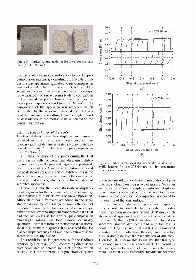
Figure 6. Typical Failure mode for the lower compressionlevel (σ= 0.5 N/mm2).
decreases, which is more significant as the level of pre-compression increases, exhibiting even negative val-ues in some specimens submitted to pre-compressionlevels of σ = 0.75 N/mm2 and σ = 1.00 N/mm2. Thisseems to indicate that as the pure shear develops,the wearing of the surface joints leads to compactionin the case of the porous lime mortar used. For thelarger pre-compression level (σ = 1.25 N/mm2), onlycompaction of the specimen was recorded, whichis revealed by the negative values of the total ver-tical displacements, resulting from the higher levelof degradation of the mortar joint associated to thecontinuous friction.
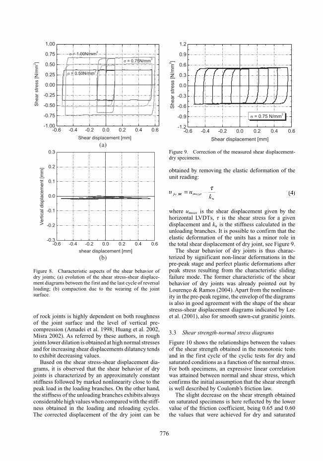
3.2.1 Cyclic behavior of dry jointsThe typical shear stress-shear displacement diagramsobtained in direct cyclic shear tests conducted inmasonry joints of dry and saturated specimens are dis-played in Figure 7 for the level of pre-compressionσ = 0.75 N/mm2.
The shear behavior of dry joints during the firstcycle agrees with the monotonic diagrams exhibit-ing nonlinearity in the pre-peak regime and post-peakplastic deformations. Apart from the distinct values ofthe peak shear stress, no significant differences in theshape of the diagrams can be found in the range of thetested normal stresses, which is valid for both dry andsaturated specimens.
Figure 8 shows the shear stress-shear displace-ment diagrams for the first and last cycles of loadingcorresponding to distinct levels of pre-compression.Although minor differences are found in the shearstrength during the reversal cycles among the distinctpre-compression levels, there seems to be a more sys-tematic tendency for a slight increase between the firstand the last cycles as the vertical pre-compressiontakes higher values. This effect is more clear in dryspecimens. Note that from the monotonic shear stress-shear displacement diagrams, it is observed that fora shear displacement of 0.1 mm, the maximum shearforces were already reached.
This result is also in agreement with the findingsreported by Lee et al. (2001) concerning direct sheartests conducted on smooth joints of granite, whichreferred that the preferential degradation of quartz
(a)
(b)
Figure 7. Shear stress-shear displacement diagrams undercyclic loading for σ= 0.75 N/mm2; (a) dry specimens;(b) saturated specimens.
grains against other rock-forming minerals could pro-vide the stick-slip on the surface of granite. When ananalysis of the normal displacement-shear displace-ment diagrams is carried out, it is possible to observea more visible tendency for compaction associated tothe wearing of the joint surface.
From the normal-shear displacement diagrams,it is possible to conclude that the values of dila-tion/compaction are not greater than ±0.06 mm, whichshows good agreement with the values reported byLourenço & Ramos (2004) for dilation obtained onsandstone smooth dry joints and with the resultspointed out by Homand et al. (2001) for hammeredgranitic joints. In both cases, the degradation mecha-nism is dominant over the phenomenon of dilatancy.Therefore, it is reasonable to assume that this typeof smooth rock joints is non-dilatant. This result isalso enlarged to the shear behavior of saturated speci-mens. In fact, it is well known that the dilatant behavior
775
(a)
(b)
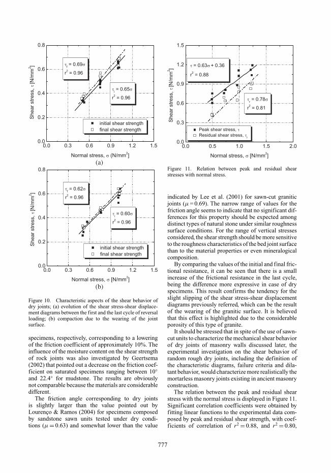
Figure 8. Characteristic aspects of the shear behavior ofdry joints; (a) evolution of the shear stress-shear displace-ment diagrams between the first and the last cycle of reversalloading; (b) compaction due to the wearing of the jointsurface.
of rock joints is highly dependent on both roughnessof the joint surface and the level of vertical pre-compression (Amadei et al. 1998; Huang et al. 2002,Misra 2002). As referred by these authors, in roughjoints lower dilation is obtained at high normal stressesand for increasing shear displacements dilatancy tendsto exhibit decreasing values.
Based on the shear stress-shear displacement dia-grams, it is observed that the shear behavior of dryjoints is characterized by an approximately constantstiffness followed by marked nonlinearity close to thepeak load in the loading branches. On the other hand,the stiffness of the unloading branches exhibits alwaysconsiderable high values when compared with the stiff-ness obtained in the loading and reloading cycles.The corrected displacement of the dry joint can be
Figure 9. Correction of the measured shear displacement-dry specimens.
obtained by removing the elastic deformation of theunit reading:
where umeas is the shear displacement given by thehorizontal LVDTs, τ is the shear stress for a givendisplacement and ku is the stiffness calculated in theunloading branches. It is possible to confirm that theelastic deformation of the units has a minor role inthe total shear displacement of dry joint, see Figure 9.
The shear behavior of dry joints is thus charac-terized by significant non-linear deformations in thepre-peak stage and perfect plastic deformations afterpeak stress resulting from the characteristic slidingfailure mode. The former characteristic of the shearbehavior of dry joints was already pointed out byLourenço & Ramos (2004). Apart from the nonlinear-ity in the pre-peak regime, the envelop of the diagramsis also in good agreement with the shape of the shearstress-shear displacement diagrams indicated by Leeet al. (2001), also for smooth sawn-cut granitic joints.
3.3 Shear strength-normal stress diagrams
Figure 10 shows the relationships between the valuesof the shear strength obtained in the monotonic testsand in the first cycle of the cyclic tests for dry andsaturated conditions as a function of the normal stress.For both specimens, an expressive linear correlationwas attained between normal and shear stress, whichconfirms the initial assumption that the shear strengthis well described by Coulomb’s friction law.
The slight decrease on the shear strength obtainedon saturated specimens is here reflected by the lowervalue of the friction coefficient, being 0.65 and 0.60the values that were achieved for dry and saturated
776
(a)
(b)
Figure 10. Characteristic aspects of the shear behavior ofdry joints; (a) evolution of the shear stress-shear displace-ment diagrams between the first and the last cycle of reversalloading; (b) compaction due to the wearing of the jointsurface.
specimens, respectively, corresponding to a loweringof the friction coefficient of approximately 10%. Theinfluence of the moisture content on the shear strengthof rock joints was also investigated by Geertsema(2002) that pointed out a decrease on the friction coef-ficient on saturated specimens ranging between 10◦and 22.4◦ for mudstone. The results are obviouslynot comparable because the materials are considerabledifferent.
The friction angle corresponding to dry jointsis slightly larger than the value pointed out byLourenço & Ramos (2004) for specimens composedby sandstone sawn units tested under dry condi-tions (µ = 0.63) and somewhat lower than the value
Figure 11. Relation between peak and residual shearstresses with normal stress.
indicated by Lee et al. (2001) for sawn-cut graniticjoints (µ = 0.69). The narrow range of values for thefriction angle seems to indicate that no significant dif-ferences for this property should be expected amongdistinct types of natural stone under similar roughnesssurface conditions. For the range of vertical stressesconsidered, the shear strength should be more sensitiveto the roughness characteristics of the bed joint surfacethan to the material properties or even mineralogicalcomposition.
By comparing the values of the initial and final fric-tional resistance, it can be seen that there is a smallincrease of the frictional resistance in the last cycle,being the difference more expressive in case of dryspecimens. This result confirms the tendency for theslight slipping of the shear stress-shear displacementdiagrams previously referred, which can be the resultof the wearing of the granitic surface. It is believedthat this effect is highlighted due to the considerableporosity of this type of granite.
It should be stressed that in spite of the use of sawn-cut units to characterize the mechanical shear behaviorof dry joints of masonry walls discussed later, theexperimental investigation on the shear behavior ofrandom rough dry joints, including the definition ofthe characteristic diagrams, failure criteria and dila-tant behavior, would characterize more realistically themortarless masonry joints existing in ancient masonryconstruction.
The relation between the peak and residual shearstress with the normal stress is displayed in Figure 11.Significant correlation coefficients were obtained byfitting linear functions to the experimental data com-posed by peak and residual shear strength, with coef-ficients of correlation of r2 = 0.88, and r2 = 0.80,
777
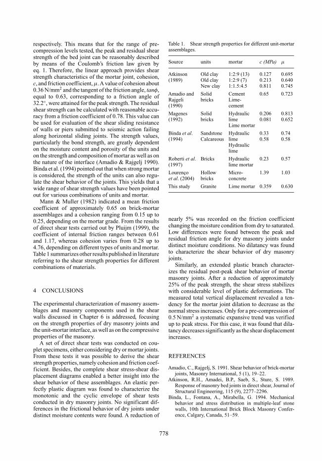
respectively. This means that for the range of pre-compression levels tested, the peak and residual shearstrength of the bed joint can be reasonably describedby means of the Coulomb’s friction law given byeq. 1. Therefore, the linear approach provides shearstrength characteristics of the mortar joint, cohesion,c, and friction coefficient, µ.A value of cohesion about0.36 N/mm2 and the tangent of the friction angle, tanφ,equal to 0.63, corresponding to a friction angle of32.2◦, were attained for the peak strength. The residualshear strength can be calculated with reasonable accu-racy from a friction coefficient of 0.78. This value canbe used for evaluation of the shear sliding resistanceof walls or piers submitted to seismic action failingalong horizontal sliding joints. The strength values,particularly the bond strength, are greatly dependenton the moisture content and porosity of the units andon the strength and composition of mortar as well as onthe nature of the interface (Amadio & Rajgelj 1990).Binda et al. (1994) pointed out that when strong mortaris considered, the strength of the units can also regu-late the shear behavior of the joints. This yields that awide range of shear strength values have been pointedout for various combinations of units and mortar.
Mann & Muller (1982) indicated a mean frictioncoefficient of approximately 0.65 on brick-mortarassemblages and a cohesion ranging from 0.15 up to0.25, depending on the mortar grade. From the resultsof direct shear tests carried out by Pluijm (1999), thecoefficient of internal friction ranges between 0.61and 1.17, whereas cohesion varies from 0.28 up to4.76, depending on different types of units and mortar.Table 1 summarizes other results published in literaturereferring to the shear strength properties for differentcombinations of materials.
4 CONCLUSIONS
The experimental characterization of masonry assem-blages and masonry components used in the shearwalls discussed in Chapter 6 is addressed, focusingon the strength properties of dry masonry joints andthe unit-mortar interface, as well as on the compressiveproperties of the masonry.
A set of direct shear tests was conducted on cou-plet specimens, either considering dry or mortar joints.From these tests it was possible to derive the shearstrength properties, namely cohesion and friction coef-ficient. Besides, the complete shear stress-shear dis-placement diagrams enabled a better insight into theshear behavior of these assemblages. An elastic per-fectly plastic diagram was found to characterize themonotonic and the cyclic envelope of shear testsconducted in dry masonry joints. No significant dif-ferences in the frictional behavior of dry joints underdistinct moisture contents were found. A reduction of
Table 1. Shear strength properties for different unit-mortarassemblages.
Source units mortar c (MPa) µ
Atkinson Old clay 1:2:9 (13) 0.127 0.695(1989) Old clay 1:2:9 (7) 0.213 0.640
New clay 1:1.5:4.5 0.811 0.745
Amadio and Solid Cement 0.65 0.723Rajgeli bricks Lime-(1990) cement
Magenes Solid Hydraulic 0.206 0.813(1992) bricks lime 0.081 0.652
Lime mortar
Binda et al. Sandstone Hydraulic 0.33 0.74(1994) Calcareous lime 0.58 0.58
Hydrauliclime
Roberti et al. Bricks Hydraulic 0.23 0.57(1997) lime mortar
Lourenço Hollow Micro- 1.39 1.03et al. (2004) bricks concrete
This study Granite Lime mortar 0.359 0.630
nearly 5% was recorded on the friction coefficientchanging the moisture condition from dry to saturated.Low differences were found between the peak andresidual friction angle for dry masonry joints underdistinct moisture conditions. No dilatancy was foundto characterize the shear behavior of dry masonryjoints.
Similarly, an extended plastic branch character-izes the residual post-peak shear behavior of mortarmasonry joints. After a reduction of approximately25% of the peak strength, the shear stress stabilizeswith considerable level of plastic deformations. Themeasured total vertical displacement revealed a ten-dency for the mortar joint dilation to decrease as thenormal stress increases. Only for a pre-compression of0.5 N/mm2 a systematic expansive trend was verifiedup to peak stress. For this case, it was found that dila-tancy decreases significantly as the shear displacementincreases.
REFERENCES
Amadio, C., Rajgelj, S. 1991. Shear behavior of brick-mortarjoints, Masonry International, 5 (1), 19–22.
Atkinson, R.H., Amadei, B.P., Saeb, S., Sture, S. 1989.Response of masonry bed joints in direct shear, Journal ofStructural Engineering, 115 (9), 2277–2296.
Binda, L., Fontana, A., Mirabella, G. 1994. Mechanicalbehavior and stress distribution in multiple-leaf stonewalls, 10th International Brick Block Masonry Confer-ence, Calgary, Canada, 51–59.
778
Calvi, G.M., Kingsley, G.R., Magenes, G. – Testing masonrystructures for seismic assessment, Earthquake Spectra,Journal of Earthquake Engineering Research Institute,12(1), 145–162, 1996.
EN 1052-3, Methods of test for masonry: Part 3 – Determi-nation of initial shear strength, 2002.
Geerstsema, A.J. 2002. The shear strength of planar joints inmudstone, International Journal of Rock Mechanics andMining Sciences, 39, 1045–1049.
Hamid, A.A., Drysdale, R.G. 1980. Behavior of brickmasonry under combined shear and compression loading,Proc. 2nd Canadian Masonry Conference, 314–320.
Hansen, K.F. 1999. Bending and shear tests with masonry,SBI Bulletin 123, Danish Building Research Insti-tute, p. 36.
Hansen, K.F., Nykänen, E., Gottfredsen, F.R. 1998. Shearbehavior of bed joints at different levels of precompres-sion, Masonry International, 12 (2), 70–78.
Homand, F., Belem, T., Souley, M. 2001. Friction and degra-dation of rock joint surfaces under shear loads, Interna-tional Journal for Numerical and Analytical Methods inGeomechanics, 25, 973–999.
Huang, T.H., Chang, C.S., Chao, C.Y. 2002. Experimentaland mathematical modeling for fracture of rock joint withregular asperities, Engineering Fracture Mechanics, 69,1977–1996.
Lee, H.S., Park, Y.J., Cho, T.F., You, K.H. 2001. Influenceof asperity degradation on the mechanical behavior ofrough rock joints under cyclic shear loading, InternationalJournal of Rock Mechanics and Mining Sciences, 38,967–980.
Lourenço, P.B., Barros, J.O., Oliveira, J.T. 2004. Shear test-ing of stack bonded masonry, Construction and BuildingMaterials, 18, 125–132.
Lourenço, P.B., Ramos, L.F. 2004. Characterization of cyclicbehavior of dry masonry joints, Journal of StructuralEngineering, 130 (5), 779–786.
Mann, W., Müller, H. 1982. Failure shear-stressed masonry– an enlarged theory, tests and application to shear walls,Proc. British Ceramic Society, 30, 223–235.
Misra,A. 2002. Effect of the asperity damage on shear behav-ior of single fracture, Engineering Fracture Mechanics, 69,1997–2014.
Pluijm, R.V.D.1999. Out-of-Plane bending of masonry,behavior and strength, PhD thesis, Eindhoven Universityof Technology. ISBN 90-6814-099-X.
Riddington, J.R., Ghazali, M.Z. 1990. Hypothesis for shearfailure in masonry joints, Proc. Instn. Civ. Engrs, 89,89–102.
Samarasinghe, W., Hendry, A.W. 1980. The tensile of brick-work under biaxial tensile and compressive stress, Proc.7th International Symposium on Load Bearing Brickwork,London, 129–139.
Vasconcelos, G. 2005. Experimental investigations on themechanics of stone masonry: characterization of granitesand behavior of stone masonry shear walls, PhD thesis,University of Minho, Portugal.
Vasconcelos, G., Lourenço, P.B., Alves, C.A.S, Pamplona, J.2007. Prediction of the mechanical properties of gran-ites by ultrasonic pulse velocity and Schmidt hammerhardness, 10th North American Masonry Conference, (inpress).
779