experimental modal analysis on flexible plate...
TRANSCRIPT
i
EXPERIMENTAL MODAL ANALYSIS ON
FLEXIBLE PLATE STRUCTURE USING
FORCED VIBRATION METHOD
AHMAD SYAFIQ BIN BAHARIN
This Report Is Submitted In
Partial Fullfillment of Requirements For the
Barchelor Degree of Mechanical Engineering (Structural & Material)
Fakulti Kejuruteraan Mekanikal
Universiti Teknikal Malaysia Melaka
APRIL 2009
ii
VERIFICATION
“I hereby declare that I have read this thesis and in my opinion this thesis is
sufficient in terms of scope and quality for the award of degree of Bachelor
Mechanical Engineering (Structure & Material)”
Signature :…………………………………
Supervisor’s Name : Puan Rainah Ismail
Date : ………………………………...

iii
SPECIALLY DEDICATED TO MY FATHER, MOTHER AND OTHER
FAMILY MEMBERS….

iv
DECLARATION
I hereby declare that this project report entitled
EXPERIMENTAL MODAL ANALYSIS ON FLEXIBLE PLATE STRUCTURE
USING FORCED VIBRATION METHOD
is written by me and is my own effort except the ideas and summaries which I have
clarified their sources.
Signature :…………………………………
Author : Ahmad Syafiq Baharin
Date : ………………………………...

v
ACKNOWLEGEMENT
Thanks to Allah, for giving me permission to complete this project. In here I
would like to record my graceful thank to all the support, encouragement and
inspirations that I have received during completing this project.
I also would like to express greatest thankfulness and appreciation to my
supervising lecturer, Pn. Rainah Ismail of which we had a good working relationship,
and who had offered me a wonderful help and encouragement. She also gives me full
of support and advice.
All the Lecturers and Technicians of Faculty of Mechanical Engineering, I
would like to acknowledge and express my gratitude for giving me their cooperation
and help in order to complete this project. Last but not least to my family and all my
fellow friends, for their concern, encouragement and understanding.

vi
ABSTRACT
Aircraft structure using the flexible structure as their main part of the body.
The body must be safe to maintain their stiffness and increase the safety. This is very
important because aircraft deal with human life. The study of experimental modal
analysis is to get the modal parameter like frequency, damping and mode shape. The
modal parameter will be analyzed to know the dynamic characteristic of structure. It
very significant to know the dynamic characteristics of the structure because
dynamic loads acting on an aircraft during flight will be encourages the onset of the
structural damage such as fatigue crack. This structural damage is often the major
cause of failure in aircraft system. This paper will discuss about the experimental
modal analysis on flexible rectangular plate structure using forced vibration method.
The forced vibration will apply at a flexible plate using the impact hammer. Then the
data obtain will be compared with the finite element model that have be done by
other researcher.
vii
ABSTRAK
Kebiasaannya, struktur pesawat menggunakan struktur yang fleksibel sebagai
rangka utama di dalam penghasilan rangka pesawat. Rangka pesawat hendaklah
selamat untuk mengekalkan kekukuhan dan juga meningkatkan tahap keselamatan
pesawat. Ini adalah amat penting kerana pesawat terlibat dengan keselamatan nyawa
manusia. Tujuan eksperimen analisis modal adalah untuk mendapatkan parameter
modal seperti frekuansi, redaman dan bentuk ragam. Parameter modal akan dianalisis
untuk mengetahui cirri-ciri dinamik sesuatu struktur. Adalah amat penting untuk
mengetahui ciri-ciri dinamik sesuatu struktur kerana daya dinamik yang bertindak ke
atas pesawat akan menghasilkan kerosakkan keatas struktur badan pesawat seperti
keretakkan. Kajian ini akan membincangkan tentang eksperimen analisis modal
keatas struktur fleksibel dengan menggunakan kaedah getaran paksa. Kaedah getaran
paksa dilakukan dengan mengenakan daya paksaan pada struktur fleksibel
menggunakan tukul impak. Data yang diperolehi akan dibezakan dengan data dari
finite element model yang telah dilakukan oleh pengkaji yang lain.

viii
CONTENTS
CHAPTER ITEM PAGE
VERIFICATION ii
DEDICATION iii
DECLARATION iv
ACKNOWLEDGMENT v
ABSTRACT vi
ABSTRAK vii
TABLE OF CONTENTS viii
LIST OF TABLE xii
LIST OF FIGURES xiii
LIST OF NOTATIONS xv
LIST OF APPENDICES xvii
CHAPTER 1 INTRODUCTION
1.1 Research Background 1
1.2 Problem Statement 2
1.3 Objective 2
1.4 Research Scope 2
1.5 Research Methodology 3

ix
CHAPTER 2 LITERATURE REVIEW
2.1 Introduction 4
2.2 Basic Vibration Theory 5
2.2.1 Vibration Theory 6
2.2.2 Equation of Motion 6
2.2.2.1 Single Degree 7
of Freedom (SDOF)
2.2.2.2 Multiple Degree 9
of Freedom (MDOF)
2.2.3 Modes of Vibration 11
2.3 Modal Analysis 12
2.3.1 Historical Background 13
Of Modal Analysis
2.3.2 Fundamental of Modal 15
Analysis
2.3.2.1 Modal Analysis Technique 17
2.3.2.2 Free and Forced Vibration 18
2.3.2.3 Frequency Response Function 19
2.3.3 Signal Processing for Modal Analysis 20
2.3.3.1 Fourier Analysis 20
2.3.3.2 Single Input Single Output 21
(SISO)
2.3.3.3 Multi Input Multi Output 22
(MIMO)
2.3.3.4 Curve Fitting 22
2.4 Forced and Ambient Method 23
2.5 Flexible Plate Structure 25
2.5.1 The Classical Dynamic 28

x
Equation of a Plate
2.5.2 Boundary Condition for 33
Clamped Rectangular Plate
CHAPTER 3 METHODOLOGY
3.1 Introduction 35
3.2 Experimental Modal Analysis 35
3.2.1 Material and Equipment 37
3.2.2 Experiment Setup 38
3.3 Initial Preparation 39
3.3.1 Setup Geometric Dimension 39
3.3.2 Software Setup 41
3.4 Experiment Procedure 45
CHAPTER 4 RESULT AND DISCUSSION
4.1 Introduction 47
4.2 Result 47
4.2.1 FFT Graph 48
4.3 Discussion 50
4.3.1 FFT Analyzer 50
4.3.2 Experimental Assumptions 51
4.3.3 Frequency Analysis 52
4.3.4 Analysis of Test Result 52
4.3.4.1 Comparison Data between 52
Experiment and True Value
4.3.4.2 Comparison Data between 58
Experiment and Simulation

xi
4.4 Experimental Error 66
CHAPTER 5 CONCLUSIONS AND RECOMMANDATIONS
5.1 Introduction 67
5.2 Conclusion 67
5.3 Recommendation for Further Study 68
REFERENCES 69 BIBLIOGRAPHY 74
APPENDICES Appendix A 75
xii
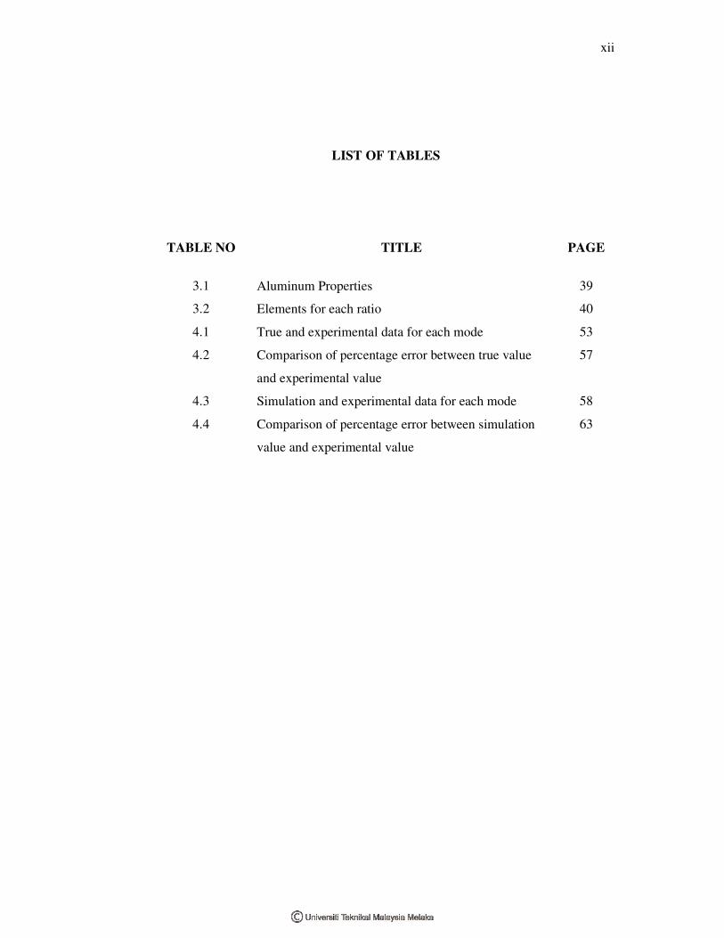
LIST OF TABLES
TABLE NO TITLE PAGE
3.1 Aluminum Properties 39
3.2 Elements for each ratio 40
4.1 True and experimental data for each mode 53
4.2 Comparison of percentage error between true value
and experimental value
57
4.3 Simulation and experimental data for each mode 58
4.4 Comparison of percentage error between simulation
value and experimental value
63

xiii
LIST OF FIGURES
FIGURE NO TITLE PAGE
1.1 Methodology Flowchart 3
2.1 SDOF discrete parameter model 7
2.2 SDOF impulse response/ free decay 8
2.3 MDOF discrete parameter model 9
2.4 MDOF impulse response/ free decay 9
2.5 MDOF frequency response 10
2.6 SDOF modal contributions 10
2.7 Mode Shape 12
2.8 A System with single input and output 19
2.9 A rectangular plate with moments 28
2.10 A rectangular plate with shear forces 29
2.11 Clamped plate for a=b 33
2.12 Clamped Plate for b=2a 34
3.1 Impact hammer 37
3.2 Accelerometer 37
3.3 Amplifier 38
3.4 Experiment setup 38
3.5 The configuration of experimental modal analysis 38
3.6 Geometric Model 40
3.7 New setup 41
3.8 Channel 2 setup 41
3.9 Channel 3 setup 42
3.10 Setup window for channel 2 and 3 42
3.11 Overwrite window 42
3.12 Option window 43
xiv
FIGURE NO TITLE PAGE
3.13 Analyze data window 43
3.14 Control properties window 44
4.1 Graph FFT for ratio a/b 0.2 49
4.2 Graph FFT for ratio a/b 0.5 49
4.3 Graph FFT for ratio a/b 0.9 50
4.4 Histogram shows the different between true and
experiment value for ratio a/b 0.2
53
4.5 Histogram shows the different between true and
experiment value for ratio a/b 0.5
54
4.6 Histogram shows the different between true and
experiment value for ratio a/b 0.9
55
4.7 Histogram shows the different between
experiment and simulation value for ratio a/b 0.2
59
4.8 Histogram shows the different between
experiment and simulation value for ratio a/b 0.5
60
4.9 Histogram shows the different between
experiment and simulation value for ratio a/b 0.9
61
4.10 Graph for frequency vs. mode for each ratio for
experiment value
64
4.11 Graph for frequency vs. mode for each ratio for
simulation value
64
4.12 Graph for frequency vs. mode for each ratio for
true value
65
xv
LIST OF NOTATIONS
m - mass system
c - damping
k - stiffness
x - displacement
x�
- velocity
x��
- acceleration
nω - natural frequency
ξ - damping ratio
[ ]m - structural mass matrix
[ ]c - structural damping matrix
[ ]k - structural stiffness matrix
{ }X - the node displacement vector
{ }X�
- the node velocity vector
{ }f(t) - the time function
( )H ω - input force function
( )Y ω - response function
f - frequency
T , t - time
ρ - pressure
h - volume density
,x yQ Q - dynamic shear force per unit length
,x yM M - moments per unit length
xyM - twisting moment per unit length

xvi
E - modulus of elasticity
� - Poisson ratio
G - shear modulus
D - flexural rigidity

xvii
LIST OF APPENDIX
Appendix
Title Page
A Setting up the FFT Analyzer for Modal Analysis
73

1
CHAPTER 1
INTRODUCTION
1.1 Research Background
Modal analysis has become a major technology in the request for
determining, improving and optimizing dynamic characteristics of engineering
structure. Modal analysis has been used in mechanical and aeronautical engineering.
Now days, modal analysis widely used in fundamental application for civil and
building structure, biomechanical problems, space structure, acoustical instruments,
transportation and nuclear plant. Contemporary design of complex mechanical,
aeronautical or civil structure required them to become increasingly lighter, more
flexible and strong. For example, the car manufactures have to achieve microscopic
reductions of product body weight. Aerospace structure such as satellite antennas
must have weight reduction of every possible gram to minimize their internal
property during operation in space.
Another relevant fact in modern life is the increasing demands of safety and
reliability upon contemporary structure defined by government regulations or by
consumer. The demands have created the challenge to the scientific understanding of
engineering structures. When the vibration of the structure being concern, the
understanding lies on better understanding on its dynamic properties using analytical,
numerical or experimental. The significance of the dynamic behavior of engineering
structure becomes important to design with proper consideration of the dynamics
characteristics.
2
1.2 Problem Statement
The current trends of space aircraft design are to use the large, thin and
lightweight structures. This is due to the many factors such as cost, safety and
mechanical parts. The vibrations are caused by the excitations. The excitations can
come from external sources such as cross wind or foundation vibration, sources
internal to the structure such as moving loads and engines. Heavy structure has small
frequency than the lighter ones. The lightweight structure will produce higher
frequency and this can lead to higher vibration. The higher vibration can cause crack,
fatigue and failure of the structure. In this study, the frequency will be determine and
analyzed.
1.3 Objective
The objectives of this study is to obtain frequency data for first three
dominant modes by using forced vibration and to verify the results with the
analytical finite element model that has been done by other researcher.
1.4 Research Scope
The scope of this study is:
1) To determine the frequency by using experimental modal analysis.
The frequency is obtained from the Fast Fourier Transform (FFT) that will be
computed by Dewesoft software used in this experiment. The flexible structure used
in this study is Al-7001 that widely used in aircraft manufacturing.
2) To compare the experimental results with the simulation data
(Nastran Patran software) and true value (Claseen and Thorne (1960)) data from
other researcher. The data will be analyzed from error aspect such as experimental
errors.

3
1.5 Research Methodology
Methodology of this study is summarized in the Figure 1.1 below
Problem Identification
Figure 1.1: Methodology Flowchart
Background Studies
Literature review on dynamic in aircraft structure
Literature review on modal analysis
Modal Testing
Modal testing on rectangular plate structure
Post-processing of measured experimental data
Comparison between theoretical and experimental result
Discussion
Conclusion and Recommendation

4
CHAPTER 2
LITERATURE REVIEW
2.1 Introduction
The term vibration describes repetitive motion that can be measured and
observed in a structure. Unwanted vibration can cause fatigue or degrade the
performance of the structure. Therefore it is desirable to eliminate or reduce the
effects of vibration. In other cases, vibration is unavoidable or even desirable. In this
case, the goal may be to understand the effect on the structure, or to control or
modify the vibration, or to isolate it from the structure and minimize structural
response.
Modal analysis is the process of determining the inherent dynamic
characteristic of a system in forms of natural frequencies, damping ratio and mode
shapes. The formulated mathematical model is referred to the modal model of the
system and the information for the characteristic is known as its modal data. Modal
analysis is based on the fact that the vibration response of a linear time-invariant
dynamic system can be expressed as the linear combination of a set of a simple
harmonic motions called the natural modes of vibrations. Modal analysis embraces
both theoretical and experimental technique.
5
2.2 Basic Vibration Theory
Vibration is the motion that repeats itself. The theory of vibration deals with
the study of oscillatory motion of bodies and associated force. The phenomenon of
vibrating involves an alternating interchange of potential energy to kinetic energy
and vice-versa. Therefore any vibrating system must have a component that stores
potential energy and a component that store kinetic energy. The components storing
potential and kinetic energy are called a spring or elastic element and a mass or
inertia element. In each cycle of motion the elastic element store potential energy and
gives it up to the inertia element as kinetic energy and vice-versa.
Vibration also consider as the transfer between the kinetic energy and
potential energy. It means the vibration systems has the storing and release both
energy. Hartog and Den (1985) argued that vibration refers to mechanical
oscillations about an equilibrium point. The oscillations may be periodic such as the
motion of a pendulum or random such as the movement of a tire on a gravel road.
Vibration is occasionally "desirable". For example the motion of a tuning fork, the
reed in a woodwind instrument or harmonica, or the cone of a loudspeaker is
desirable vibration, necessary for the correct functioning of the various devices.

6
2.2.1 Vibration Types
Vibrations can be classified into following type (Rao, 2004).
1. Undamped and Damped vibration
If there is no less or dissipation of energy due to friction or other resistance
during vibration of a system, the system said to be undamped. If there is a energy
loss to the presence of damping, the system is called damped. Although system
analysis is simpler when neglect damping, a consideration of damping become
extremely important if a system operates near resonans.
2. Free and Forced vibrations
If a system vibrations due to an initial disturbance (with no external force
applied after time zero), the system said to undergo free vibrations. On other
hand if the system vibrates due to the applications of external force, the system
said to be under forced vibrations.
3. Linear and nonlinear vibrations
If all the basic components of a vibrating system (i.e. the mass, the spring and
the damper) behave linearly, the resulting vibrating is called linear vibration.
However, if any of the basic components at a vibrating system behave
nonlinearly, the resulting vibration is called nonlinear vibration.
2.2.2 Equation of Motion
A basic understanding of structural dynamic is necessary for successful
modal testing. It is important to have a good grasp of the relationship between
frequency response function and modal parameter. Knowing of the various forms
and trends of frequency response functions will lead to more accuracy during
measurement phase. During the analysis phase, knowing how equations relate to
frequency response leads to more accurate estimation of modal parameters.

7
2.2.2.1 Single Degree of Freedom (SDOF)
Figure 2.1: SDOF discrete parameter model
Although most physical structure is continuous, their behavior can usually
represent by a discrete parameter model as illustrated in Figure 2.1. The idealization
elements are called mass, spring, damper and excitation. The first three elements are
described the physical system. Energy is stored by the system in the mass and the
spring in the form of kinetic and potential energy. Energy enters the system through
excitation and dissipated through damping.
( )m x c x kx f t+ + =�� �
2, 2 ,
2nn
k c c
m m k mξ ω ξω = = = (2.1)
The idealized elements of the physical system can be described by the equation of
motion shown in (2.1). This equation relates the effect of the mass, stiffness and
damping in a way that leads to the calculation of natural frequency and damping
factors of the system.
This computation is often facilitated by the use of definition shown in (2.1)
that leads directly to the natural frequency and damping factors. The natural
frequency, ω, is in unit of radians per second (rad/s). The typical units displayed on a
digital analyzer however are in Hertz (Hz). The damping factor can also represent as