experimental methods for mobility and surface...
TRANSCRIPT
Experimental Methods for Mobility and SurfaceOperations of Microgravity Robots
Benjamin Hockman1, Robert G. Reid2, Issa A. D. Nesnas2, and Marco Pavone1
1 Dept. of Aeronautics and Astronautics, Stanford University, Stanford, CA. 94305{bhockman, pavone}@stanford.edu
2 Jet Propulsion Laboratory, California Institute of Technology, Pasadena, CA. 91109{rgreid, nesnas}@jpl.nasa.gov
Abstract We propose an experimental method for studying mobilityand surface operations of microgravity robots on zero-gravity parabolicflights—a test bed traditionally used for experiments requiring strictlyzero gravity. By strategically exploiting turbulence-induced “gravity fluc-tuations,” our technique enables a new experimental approach for testingsurface interactions of robotic systems in micro- to milli-gravity environ-ments. This strategy is used to evaluate the performance of internally-actuated hopping rovers designed for controlled surface mobility on smallSolar System bodies. In experiments, these rovers demonstrated a rangeof maneuvers on various surfaces, including both rigid and granular. Res-ults are compared with analytical predictions and numerical simulations,yielding new insights into the dynamics and control of hopping rovers.
1 Introduction
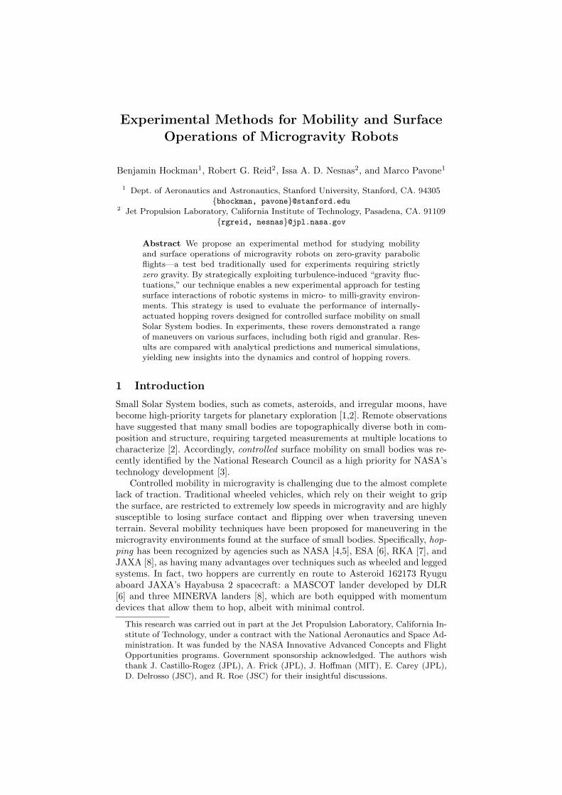
Small Solar System bodies, such as comets, asteroids, and irregular moons, havebecome high-priority targets for planetary exploration [1,2]. Remote observationshave suggested that many small bodies are topographically diverse both in com-position and structure, requiring targeted measurements at multiple locations tocharacterize [2]. Accordingly, controlled surface mobility on small bodies was re-cently identified by the National Research Council as a high priority for NASA’stechnology development [3].
Controlled mobility in microgravity is challenging due to the almost completelack of traction. Traditional wheeled vehicles, which rely on their weight to gripthe surface, are restricted to extremely low speeds in microgravity and are highlysusceptible to losing surface contact and flipping over when traversing uneventerrain. Several mobility techniques have been proposed for maneuvering in themicrogravity environments found at the surface of small bodies. Specifically, hop-ping has been recognized by agencies such as NASA [4,5], ESA [6], RKA [7], andJAXA [8], as having many advantages over techniques such as wheeled and leggedsystems. In fact, two hoppers are currently en route to Asteroid 162173 Ryuguaboard JAXA’s Hayabusa 2 spacecraft: a MASCOT lander developed by DLR[6] and three MINERVA landers [8], which are both equipped with momentumdevices that allow them to hop, albeit with minimal control.
This research was carried out in part at the Jet Propulsion Laboratory, California In-stitute of Technology, under a contract with the National Aeronautics and Space Ad-ministration. It was funded by the NASA Innovative Advanced Concepts and FlightOpportunities programs. Government sponsorship acknowledged. The authors wishthank J. Castillo-Rogez (JPL), A. Frick (JPL), J. Hoffman (MIT), E. Carey (JPL),D. Delrosso (JSC), and R. Roe (JSC) for their insightful discussions.

2 B. Hockman et al.
1.1 Hedgehog Hopping Rover
This paper considers, as a case study, a hopping rover developed by the au-thors called “Hedgehog,” which utilizes internal actuation (via three mutually-orthogonal flywheels) to generate controlled directional hops in microgravity (seeFig. 1, left). Specifically, by applying an internal torque on the flywheels viamotors and mechanical brakes, the chassis rotates and induces external reac-tion forces on the surface, producing ballistic hops (see Fig. 1, right). This mo-bility technique, as investigated in [9,10,11], offers a simple, yet uniquely cap-able, architecture for targeted mobility on small bodies (see overview video at:http://youtu.be/bDmoqjNQAu8). Specifically, [11] derives flywheel control lawsfor a variety of “motion primitives” (e.g., hopping, tumbling, and twisting) thathave demonstrated a previously unobtained level of precision in simulations andground-based experiments.
Figure 1. Left: Hopping rover prototype shown without avionics, covers, or solar pan-els. The cubic chassis encloses three orthogonal flywheels and is surrounded by eightcompliant spikes on its corners. Right: By accelerating internal flywheels, surface reac-tion forces cause the rover to tumble or hop.
1.2 Experiments in Microgravity
One of the most challenging tasks when developing robotic systems for micro-gravity is testing in relevant environments. Here, and throughout this paper,“microgravity” refers to the small, but importantly, non-zero gravity (roughly10−5 to 10−2 g’s) exerted by a small body. At these scales, surface reaction forcesare small and motion is slow, so it is not practical or comparable to test micro-gravity systems in 1 g environments (as can be done, for example, with Martianrovers). This is an issue for mobility systems as well as other surface operationssuch as excavation or anchoring devices. Instead, there have been various methodsproposed for emulating reduced gravity on Earth, which can be roughly dividedinto two classes: (1) free-fall test beds, such as drop towers and parabolic flights,and (2) gravity-offloading test beds that aim to “counteract” the force of gravity.
Various gravity-offloading approaches have been demonstrated, including buoy-ancy tanks, air-bearing tables [9], passive counterweight mechanisms [9,10], andactively controlled tracking systems [11,12,13,14]. Gravity-offloading test bedsgenerally allow for longer duration and less expensive tests than free fall cham-bers, but they typically introduce undesirable exogenous dynamics and/or restrictthe system’s range of motion. For the Hedgehog rover presented in Sect. 1.1, Hock-man et al. developed a first-of-a-kind test bed at Stanford University, uniquelycapable of tracking the Hedgehog’s motion in 6 degrees of freedom (DoF) underdynamic force inputs [11]. It consists of an actively-controlled overhead 3-axis

Experimental Methods for Microgravity Robots 3
gantry crane that tracks the translational motion of the Hedgehog at an effect-ive 0.0005 - 0.005 g’s, and a passive gimbal that allows the Hedgehog to freelyrotate about all three axes (see Fig. 2). While this test bed has demonstratedeffective tracking performance for some types of maneuvers such as small hopsand tumbles, it has three inherent limitations: (1) it cannot track fast maneuverssuch as more aggressive hops, (2) the added mass and inertia of the gimbal pre-vent accurate tracking of rotations about non-symmetric axes, and (3) it cannotoffload the surface regolith’s mass, which, especially for loose granular materials,can behave quite differently in microgravity.
Figure 2. The Stanford6 DoF microgravity test.The powered gantrytracks the translationalmotion of the Hedgehog,while allowing for free fallat sub-milli-g levels. Thegimbal frame allows theHedgehog to rotate in allthree axes.
Statement of Contributions: The contributions of this paper are twofold:first, we propose a novel experimental method that utilizes zero-g parabolicflights—a test bed traditionally used for experiments requiring strictly zero gravity— for testing microgravity surface operations (Sect. 2). Our approach exploitsthe “gravity fluctuations” induced by turbulence on the aircraft to trigger exper-iments during windows of acceptable conditions. The proposed technique avoidsmany of the limitations observed in gravity-offloading test beds, and thus offersa complementary approach to testing robotic systems, such as Hedgehog, thatare designed for microgravity environments. Second, we use this experimentalprocedure to evaluate the controllability of two Hedgehog prototypes perform-ing various maneuvers on several rigid and granular surfaces. The results largelyagree with predictions based on analytical and numerical models (Sect. 3). Tothe best of the authors’ knowledge, these experiments constitute some of the firstdemonstrations of controlled hopping on a zero gravity aircraft.
2 Parabolic Flight Experiments
Parabolic flights offer a unique environment to conduct experiments in effect-ively reduced gravity, but they pose significant challenges for systems that re-quire smooth and stable accelerations. During each parabola, disturbances causedby turbulence and control errors induce “gravity fluctuations” on the order of±0.03 g’s. Figure 3 shows a representative example of time-series accelerationdata collected on NASA’s C9 aircraft. Brief periods of negative g’s are particu-larly problematic for unrestrained robots that need to remain in contact with asurface (such as our Hedgehog), since they will inadvertently float away.
One solution is to “positively bias” the effective gravity such that it nevergoes negative. Typically, this can only be afforded for a small fraction of para-bolas since multiple experimental payloads are flown on each flight, and most

4 B. Hockman et al.
require net-zero gravity. During zero-g parabolas, however, gravity fluctuationsoften produce brief periods with slightly positive gravity conditions that can beutilized for microgravity experiments. With this in mind, we propose an experi-mental method that systematically exploits these fluctuations to enable surface-interaction experiments with microgravity robotic systems.
0 5 10 15 20 250.02
0.01
0.00
0.01
0.02
0.03
0.04
0.05
0.06
Acc
ele
rati
on (
g)
Magnitude
Fore/aft (Gx)
Lateral (Gy)Vertical (Gz)
0 5 10 15 20 25Time (seconds)
020406080
100120140160180
Slo
pe (
deg
rees)
Effective Slope
Figure 3. Example time-series acceleration data from C9 reduced gravity aircraft duringa parabola. Top: Accelerations of the aircraft in the aircraft reference frame. Bottom:Effective slope of the experimental payload; 0◦ is horizontal, while 90◦ is sideways.
Our experimental setup is as follows (see Fig. 4): the Hedgehog prototype sitson the test surface and is restrained by a retractable arm that applies a gentledownwards force. An accelerometer, rigidly mounted to the floor of the aircraft,measures the transient accelerations and is used to automatically retract the armand initiate each experiment when the resulting gravity conditions are deemedacceptable. An array of small cameras fixed inside the payload container trackthe Hedgehog’s motion (position and attitude) with millimeter precision and highframe rates (240 Hz) via body-mounted fiducial markers. Some cameras were alsofocused on the surface to observe contact interactions.
Figure 4. Experimental setup. Left: The Hedgehog (A) is held in place on the testsurface (C) by an actuated arm (B). An array of five cameras (D) capture its motion asit hops within the container. Right: Photo of our experiments on NASA’s C9 aircraft.
“Acceptable” gravity conditions for triggering an experiment should be tailoredfor the particular system being tested. Since Hedgehog actuates while in contact
Experimental Methods for Microgravity Robots 5
with the surface, for example, we defined the triggering condition as the firstpoint at which (1) the total acceleration magnitude is less than 0.02 g’s (with alow-pass filter) and (2) the effective slope is less than 30◦ relative to the surfacenormal (to avoid sliding or tipping before actuation). The shaded region in Fig. 3shows the time at which an experiment was triggered for that particular parabola.Historical acceleration data for the particular aircraft should be analyzed to val-idate the desired triggering condition and to predict the percentage of parabolasthat would allow successful triggering. Thus, for experiments with flexible gravityrequirements, there is an inherent trade between the acceptable parabola qualityand probability of a trigger occurring.
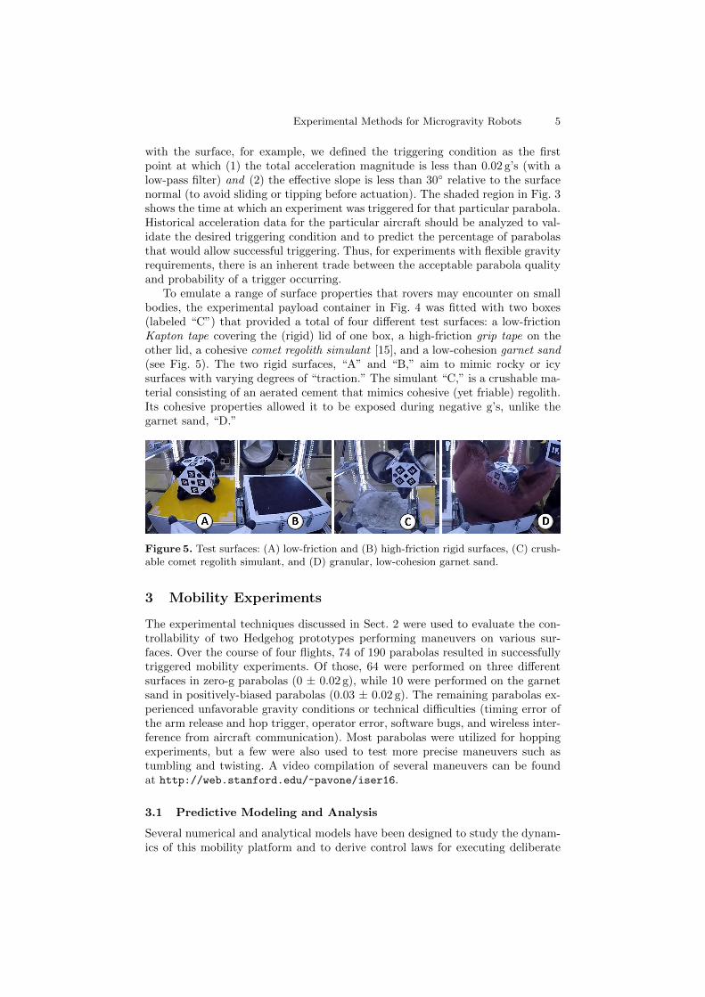
To emulate a range of surface properties that rovers may encounter on smallbodies, the experimental payload container in Fig. 4 was fitted with two boxes(labeled “C”) that provided a total of four different test surfaces: a low-frictionKapton tape covering the (rigid) lid of one box, a high-friction grip tape on theother lid, a cohesive comet regolith simulant [15], and a low-cohesion garnet sand(see Fig. 5). The two rigid surfaces, “A” and “B,” aim to mimic rocky or icysurfaces with varying degrees of “traction.” The simulant “C,” is a crushable ma-terial consisting of an aerated cement that mimics cohesive (yet friable) regolith.Its cohesive properties allowed it to be exposed during negative g’s, unlike thegarnet sand, “D.”
Figure 5. Test surfaces: (A) low-friction and (B) high-friction rigid surfaces, (C) crush-able comet regolith simulant, and (D) granular, low-cohesion garnet sand.
3 Mobility Experiments
The experimental techniques discussed in Sect. 2 were used to evaluate the con-trollability of two Hedgehog prototypes performing maneuvers on various sur-faces. Over the course of four flights, 74 of 190 parabolas resulted in successfullytriggered mobility experiments. Of those, 64 were performed on three differentsurfaces in zero-g parabolas (0 ± 0.02 g), while 10 were performed on the garnetsand in positively-biased parabolas (0.03 ± 0.02 g). The remaining parabolas ex-perienced unfavorable gravity conditions or technical difficulties (timing error ofthe arm release and hop trigger, operator error, software bugs, and wireless inter-ference from aircraft communication). Most parabolas were utilized for hoppingexperiments, but a few were also used to test more precise maneuvers such astumbling and twisting. A video compilation of several maneuvers can be foundat http://web.stanford.edu/~pavone/iser16.
3.1 Predictive Modeling and Analysis
Several numerical and analytical models have been designed to study the dynam-ics of this mobility platform and to derive control laws for executing deliberate

6 B. Hockman et al.
maneuvers (see [11] for details). By simplifying the rover’s geometry, and assum-ing instantaneous momentum transfer with no slipping during contact, the twomodels in Fig. 6 A and B allow control laws to be derived analytically from rigidbody dynamics and angular momentum arguments. These control laws dependon the rover’s geometric and inertial properties, as well as its resting pose on thesurface. For hopping with high-torque brakes, these control laws map a desiredtakeoff velocity vector to the prerequisite angular speeds of the flywheels.
Figure 6. Dynamic Models. A: 2D model used to derive control laws for single-axis hops[11]. B: Hedgehog is modeled as a cube pivoting on one of its corners, which is usedto derive control laws for directional hops [11]. C: A numerical contact model assumesCoulomb friction and arbitrary penetrating force function.
To study more realistic dynamics, a penetrating contact model was designedto allow slip and surface deformation that is numerically integrated to solvefor the Hedgehog’s trajectory (see Fig. 6C). By varying the friction coefficients(µs, µk) and the penetration force function (F ) this “elastic sliding block” modelcan approximate a wide variety of surface properties. For most rigid (or near-rigid) surfaces, a damped elastic model works well (i.e. F = kl + bl), but morecomplex nonlinear models can also be devised to capture surface deformation ef-fects. While a numerical approach does not yield analytical control insights, it isuseful for understanding motion on irregular surfaces and the response in sub-sequent surface collisions. These models can now serve as a basis for comparisonwith data collected on microgravity experiments.
3.2 Hopping Experiments
Since the dynamics of a hopping rover in ballistic flight are deterministic (foran airless body with known spin and gravity model), we can characterize theresulting trajectory with three parameters describing its initial launch velocityvector: speed (vh), elevation angle (θh), and azimuth angle (φh). These parametersare extracted from the visual tracking data by fitting a parabola to the time-seriesposition measurements of the Hedgehog’s mass center for the first 20 cm of itstrajectory after takeoff. The observed hop vectors can then be compared withpredictions obtained by inputting the observed flywheel speeds into our models.
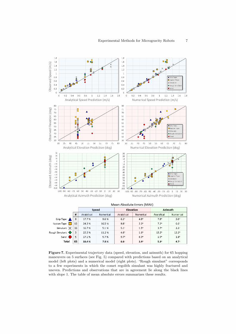
The results in Fig. 7 show predicted values on the horizontal axis and meas-ured trajectory data on the vertical axis. Each data point represents a trajectoryresulting from a particular set of flywheel speeds. The analytical model used forcomparison in the left plots is shown in Fig. 6B, and the numerical model forthe right plots, in Fig. 6C. Overall, there was strong agreement between the ex-perimental and model-generated data with mean absolute errors of about 10%for speed, and 5◦ for elevation and azimuth angles. It is important to note thatHedgehog experienced slight drift before actuation on many of these maneuvers,such that its initial state was not exactly grounded and stationary, as assumed
Experimental Methods for Microgravity Robots 7
Figure 7. Experimental trajectory data (speed, elevation, and azimuth) for 65 hoppingmaneuvers on 5 surfaces (see Fig. 5) compared with predictions based on an analyticalmodel (left plots) and a numerical model (right plots). “Rough simulant” correspondsto a few experiments in which the comet regolith simulant was highly fractured anduneven. Predictions and observations that are in agreement lie along the black lineswith slope 1. The table of mean absolute errors summarizes these results.

8 B. Hockman et al.
by the analytical model. Therefore, it is not surprising that the numerical model,which is simulated from the actual measured initial states and accounts for thevarying surface properties, exhibits stronger agreement with the data than theless-informed analytical model.
Examining systematic bias in the data can help to identify unmodeled ef-fects and make improvements. For example, the clustering of analytical elevationpredictions at 45◦ reflects the no-slip and instantaneous momentum transfer as-sumptions for single-axis hops, which are not realizable for lower friction surfacesand brakes with limited torque. If, however, information about the surface frictionis known a priori, the control law can be adjusted to reflect the higher expectedelevation (θh ≈ cot−1 µ). Also, contact interactions with loose granular regolith,which is essentially “fluidized” by microgravity, does not adhere well to eitherthe pin-jointed spike contact assumption or the numerical contact model (suchas overestimated hop elevation on sand in Fig. 7); it will be the subject of futurework. Finally, it is suspected that the high-speed outliers can be attributed to atemporary hardware issue with one of the prototype’s braking mechanisms.
3.3 Tumbling Experiments
Tumbling is simply a less energetic form of hopping, whereby the Hedgehog rotatesabout a pair of spikes without losing ground contact, nominally rotating 90◦ andtranslating one body length. For this single-flywheel maneuver, an upper andlower bound on the control input are derived in [11], which correspond to thespeed at which the Hedgehog would rotate too fast and lose surface contact andthe speed at which it would just barely tip over, respectively.
ωmax =
√g cosβ
η2l cosα, ωmin =
√2mpgl(1− cos(α+ β))
ηIf. (1)
These bounds are functions of the Hedgehog’s inertial and geometric properties(mp, If, η, α, l), its initial pose (β), and gravity (g) (see [11] for details). However,due to the need to maintain continuous ground contact over a longer time period,tumbling maneuvers could not exploit brief gravity transients and were thereforerestricted to positively-biased parabolas. Table 1 summarizes data for the twotumbles performed.
Trial Surface Inclination* ωmin (rpm) ωmax (rpm) ω (rpm) Success?
1 sand −10.7◦ 1451 2937 1968 Yes2 sand −22.7◦ 255 837 274 Yes
Table 1. Data from two successful tumbling experiments on sand at about 0.035 g’s.Note that the measured flywheel speed (ω) is indeed between the predicted minimumand maximum bounds (see Eq. 1). *Negative inclination indicates a “downhill” tumble.
While the data is sparse, a few insightful observations were made. For one, onloose granular media, the leading spikes tend to sink into the surface, which shiftsthe pivoting axis inward and effectively shortens the modeled spike length (l).Also, faster tumbles have a higher chance of producing undesirable rebounds uponimpact. However, both of these incidental effects can be mitigated by operatingin the lower speed range (e.g. 10% higher than ωmin).

Experimental Methods for Microgravity Robots 9
4 Main Experimental Insights
Despite the negative gravity fluctuations, accelerometer data indicates that ap-proximately 40% of parabolas in NASA’s C-9 aircraft yield acceptable conditionsfor brief microgravity mobility experiments, proving that parabolic flights canbe a viable test bed for microgravity robotic systems. Moreover, for other short-duration microgravity experiments that can be executed in quick succession, someparabolas may offer multiple opportunities to collect data. This was not possiblewith our Hedgehog prototypes, as they require time to accelerate the flywheels.
An intuitive way of understanding the hopping uncertainty is by consideringthe transfer of angular momentum from the flywheel to the Hedgehog, which isassumed to be conserved about the pivoting spike(s) in the control analysis. In-deed, among the hops that did not experience initial drift, the momentum sawa mean loss of only 7%. Importantly, however, this angular momentum can bedecomposed into the sum of linear (r × p) and rotational (I · ω) components,which can be thought of as the “speed” and “spin” of the Hedgehog. Since weare primarily concerned with the translational trajectory, it is important to un-derstand what portion of the flywheel momentum is converted to linear motionof the mass center. In theory, for the pin-jointed contact model in Fig. 6A, linearand rotational momentum should be in fixed proportions, ml2 ∝ I, respectively,where m is the mass, l is the spike length, and I is the centroidal inertia. However,there are certain conditions for which these proportions can be distorted. Contactelasticity, for example, can induce a recoil effect as the spikes push against thesurface, which reduces the forward spin and increases the speed of the hop. In ex-treme cases, this may even induce a counter-rotation, and thus, much faster hops.Although elasticity generally yields more efficient hops, it is also less predictable,suggesting that more damping/shock-absorbing spikes may be favorable.
Surface slip, on the other hand, has the opposite effect: on low-friction surfaces,the planted spikes tend to slip, or “sweep” under the hopper and incur fasterspinning, yet slower hops (which also increases the hop elevation to θh ≈ cot−1 µ).That said, a smooth Coulomb friction model is likely a gross oversimplificationfor the deformable and irregular surfaces likely to be found on small bodies.For example, the comet regolith simulant described in Sect. 2 is smooth to thetouch but often crushed under the pressure of the spikes during a hop, creatinga secure foothold that prevents slip. Thus, future work will consider alternativespike designs that include small features to penetrate and grip the surface.
In addition to hopping and tumbling, twisting maneuvers were also testedwhereby the Hedgehog spins about its vertical axis. This can be leveraged ina controlled way to rotate by some small angle, as discussed in detail in [11].This was only tested once on sand in 0.03 g’s, which produced a small angularshift as expected. While not directly useful for controlled mobility, aggressivetwisting maneuvers (e.g. twists that result in more than one full revolution) couldbe utilized to energetically escape when embedded in loose regolith. One suchmaneuver was executed while the Hedgehog was partially embedded in the garnetsand; it ejected all sand within its swept radius and the Hedgehog was launchedvertically.
The various ways in which surface properties can affect mobility performanceraises an interesting question for further research: the inverse problem—that is—given some known control input and corresponding force on the surface, howcan information about physical properties of the surface be extracted from the

10 B. Hockman et al.
dynamic response. Even constraining bulk properties, such as regolith density,depth, and cohesion, would provide useful information for mission designers andplanetary scientists alike.
In the broader context of motion planning and navigation on small bodies, theultimate goal is to reach designated targets, and the controllability of hopping,demonstrated in this paper, is simply one factor that enables this. The dynam-ics of subsequent bouncing and the physical and topographical properties of theenvironment also play a critical role. Thus, it is perhaps more important to char-acterize the uncertainty of a hop than it is to further refine its accuracy with morecomplex control regimes. The experiments enabled by our method for strategicmicrogravity testing—and the improved models they inspire—offer unique insighttowards achieving this goal.
References
1. “Decadal Survey Vision and Voyages for Planetary Science in the Decade 2013–2022,” National Research Council, Tech. Rep., 2011.
2. J. C. Castillo Rogez, M. Pavone, I. A. D. Nesnas, and J. A. Hoffman, “ExpectedScience Return of Spatially-Extended In-situ Exploration at Small Solar SystemBodies,” in IEEE Aerospace Conference, Big Sky, MT, Mar. 2012, pp. 1–15.
3. “NASA Space Technology Roadmaps and Priorities: Restoring NASA’s Technolo-gical Edge and Paving the Way for a New Era in Space,” National Research Council,Tech. Rep., 2012.
4. R. Jones, “The MUSES–CN rover and asteroid exploration mission,” in 22nd Inter-national Symposium on Space Technology and Science, 2000, pp. 2403–2410.
5. P. Fiorini and J. Burdick, “The Development of Hopping Capabilities for SmallRobots,” Autonomous Robots, vol. 14, no. 2, pp. 239–254, 2003.
6. C. Dietze, S. Herrmann, F. Kuß, C. Lange, M. Scharringhausen, L. Witte, T. vanZoest, and H. Yano, “Landing and mobility concept for the small asteroid landerMASCOT on asteroid 1999 JU3,” in International Astronautical Congress, 2010.
7. R. Z. Sagdeev and A. V. Zakharov, “Brief History of the Phobos Mission,” Nature,vol. 341, no. 6243, pp. 581–585, Oct. 1989.
8. “JAXA Hayabusa mission,” JAXA, Tech. Rep., 2011, available at http://hayabusa.jaxa.jp/e/index.html.
9. R. Allen, M. Pavone, C. McQuin, I. A. D. Nesnas, J. C. Castillo Rogez, T.-N.Nguyen, and J. A. Hoffman, “Internally-Actuated Rovers for All-Access SurfaceMobility: Theory and Experimentation,” in Proc. IEEE Conf. on Robotics and Auto-mation, Karlsruhe, Germany, May 2013, pp. 5481–5488.
10. R. G. Reid, L. Roveda, I. A. D. Nesnas, and M. Pavone, “Contact Dynamics ofInternally-Actuated Platforms for the Exploration of Small Solar System Bodies,”in i-SAIRAS, Montreal, Canada, Jun. 2014, pp. 1–9.
11. B. Hockman, A. Frick, I. A. D. Nesnas, and M. Pavone, “Design, Control, andExperimentation of Internally-Actuated Rovers for the Exploration of Low-GravityPlanetary Bodies,” in Conf. on Field and Service Robotics, Toronto, Canada, 2015.
12. M. Chacin and K. Yoshida, “A Microgravity Emulation Testbed for Asteroid Ex-ploration Robots,” in Proc. i-SAIRAS, 2008.
13. B. H. Wilcox, “ATHLETE: A limbed vehicle for solar system exploration,” inAerospace Conference, 2012 IEEE. IEEE, 2012, pp. 1–9.
14. P. Valle, L. Dungan, T. Cunningham, A. Lieberman, and D. Poncia, “Active Re-sponse Gravity Offload System,” 2011.
15. E. M. Carey, G. H. Peters, L. Chu, Y. M. Zhou, B. Cohen, L. Panossian, M. Chouk-roun, J. R. Green, P. Backes, S. Moreland, and L. R. Shiraishi, “Development andcharacteristics of mechanical porous ambient comet simulants as comet surface ana-logs,” in Lunar and Planetary Science Conference, 2016.