experimental investigations and ageing studies on...
TRANSCRIPT

International Journal on Electrical Engineering and Informatics ‐ Volume 6, Number 1, March 2014
Experimental Investigations and Ageing Studies on Effects of Insulating Barriers in Transformer Oil during High Frequency High Voltage
Transients in Inhomogeneous Field
S. Venkatesh and M. Balasubramanian
Department of Electrical and Electronics Engineering, School of Electrical and Electronics Engineering, SASTRA University, Thanjavur- 613 401, India. [email protected] , [email protected]
Abstract: Insulating barriers utilized in complex high voltage insulation systems has been exploited widely by manufacturers of power apparatus. Barriers have found utility in a variety of power apparatus for protection against direct lightning strokes, as an interface at the boundaries of composite insulation materials etc. Though investigations have been carried out by researchers on the breakdown characteristics, barrier position in the gap, influence of space charge etc these characteristics have been analyzed based on aspects pertinent to classical testing procedures only. Advent of high speed switching devices in power systems provides avenues to investigate the effect of insulation performance due to High Frequency High Voltage (HFHV) also. Further, uncharacteristic failures in oil filled distribution transformers have been reported indicated fast transients as the major cause for failures which was not revealed during classical laboratory testing. This research focuses on the influence and effects of solid insulating barriers placed in transformer oil due to HFHV in inhomogeneous fields. Test cell arrangement has been fabricated for carrying out experimental investigations to adhere international standards. Exhaustive experimentation has been performed to infer the influence of the position of barrier, nature of field and breakdown voltage, erosion characteristics of the barrier at an appropriate range of frequencies. A detailed comparison between HFHV and classical power frequency voltage has been carried out. The nature of ionization at the barrier interface and the subsequent increase in the breakdown voltage as explained by Double Electric Layer (DEL) theory has been cross validated. In addition, a study has also been carried out to assess and characterize the ageing of oil based on Dissolved Gas Analysis (DGA) analysis using Weibull distribution. Keywords: High Frequency High Voltage- HFHV; Double Electric Layer- DEL; Barrier; Dissolved Gas Analysis – DGA
1. Introduction The concept of introducing a dielectric barrier in insulation system of high voltage power equipment has been exploited widely since it has been substantiated during experimental studies and detailed analysis that the withstand voltage strength of the insulation system considerably increases. Insulating barriers have found utility in a wide variety of critical equipments of power system such as spacers in transformers, as end rings (shield rings) for lightning protection against lightning strokes in transformers, as nano-dielectrics for enhanced voltage withstand capability of composite insulation system etc. Researchers have carried out substantial studies utilizing barriers to analyze the characteristics and performance of the composite insulation system such as withstand voltage, role of barrier location in the gap, ratio of permittivity of the insulating barrier and the primary dielectric, influence of the space charge etc. However, most of these studies have been confined to analysis based on classical voltage test procedures (power frequency, impulse voltages- switching and lightning).
Received: October 24th, 2013. Accepted: January 20th, 2014
13

However, in recent times, investigations on the effect of insulation performance due to high frequency high voltages have gained attention and focus among researchers, since it has relevance in applications related to high speed switching circuits such as IGBT, GTO, converter transformers switches, etc. Also unpredicted failures in oil-filled distribution transformers have been reported [1] in the recent years which have been attributed to fast transients (high frequencies) which have not been disclosed during classical/ standard tests (a.c power frequency withstand test and impulse test– lightning and switching) conducted in laboratory. Studies and analysis by a group of researchers [1] clearly indicated an increase in voltage stresses due to high frequencies and unconventional wave shapes which was attributed to major cause for such failures and in a number of studies related to the internal resonance. The scientific and research community has ever since embarked on providing comprehensive solutions to comprehend this obscure aspect by formulating a working group, IEEE C57.142 [2] as a part of the IEEE Transformer Committee with the principal focus on creating a testing procedure that would include methodologies related to transient (high frequency) voltages induced by resonant, switching etc. The goal of this research is to infer on the nature and position of barrier in transformer oil in an inhomogeneous field due to HFHV transients. Detailed studies and analysis is carried out on solid barrier (Kraft paper) due to HFHV transients in an inhomogeneous field placed in transformer oil. Studies related to the role of voltage withstand strength due to classical and HFHV tests are taken up to ascertain the role played by the position of the barrier, nature of inhomogenity in electric field and erosion characteristics during breakdown of barrier. In addition degradation in oil samples is also characterized utilizing the two parameter and three parameter Weibull distribution based on dissolved gas analysis. 2. Basic Concepts of HFHV and Barrier Effect Studies by researchers have revealed that primarily five unique ranges of frequencies are obtained which are related to the frequency dependence of breakdown voltage and have different characteristics with specific physical processes [3]. Figure 1 shows a plot indicating breakdown voltage for the five distinct ranges of frequencies.
Figure 1. Plot of Breakdown Voltage and Frequency
During measurements up to a frequency called the ‘critical frequency (fcr), breakdown voltage independent of frequency and it is governed by elementary breakdown processes such as ionization, streamer mechanism etc. At a frequency beyond the critical value decrease in breakdown voltage is observed with increase in frequency. This is usually attributed by the role played by volumetric charges. This aspect is due to the less rapid frequency whereby the ions produced in a half period have enough time to reach the electrodes during this period while and in next half period the process starts in the absence of volume charge. However, as the frequency increases further, a small part of the ions (usually the positive ions due to its mass as
S. Venkatesh, et al.
14

compared to the electrons) do not acquire sufficient time to reach the electrodes. Hence, the quantum of ions left over in the gap between the electrodes keeps increasing which reduces the breakdown voltage. This aspect explains the reason for lesser values of breakdown voltage in range 2 of Figure 1 shown. However, at frequency ‘f2’, there is a possibility of further decrease in the breakdown voltage. The half period duration of voltage is seemingly lesser than the time duration taken by electrons to travel the spacing in between the electrode configurations. Thus, a segment of negative charges (electrons) remain in space and participates in the ionization process thus leading to a further reduction in breakdown voltage value. At very high frequencies (Range 5), increase of breakdown voltage is observed which may be ascribed to very drastic reduction in the half period which becomes insufficient to initiate the process of ionization. Further field enhancement and hence additional applied voltage would be essential to breakdown the insulation system. The effect of barrier [4] in HV (High Voltage) engineering essentially relates to an increase in the breakdown strength (enhancement of withstand voltage of the insulation system) because of the usage of many additional layers of insulation which are located in the primary insulation. The effect is widely applied in HV equipment design with a standard needle-plane electrode configuration to enhance the breakdown strength. Preliminary studies by Marx and Rozer reported the role of enhanced withstand strength due to barriers during the discharge studies in air gaps irrespective of the dielectric medium's phase (liquid, gaseous, or solid), voltage type (DC, AC power frequency or Lightning Impulse (LI) and Switching Impulse (SI)) [5], configuration of electrode (needle-plane or plane-plane configuration) and inter-electrode distance of air gap (short, medium and long gaps). Though many experimental studies [6] have been carried out to address this problem, the barrier effect mechanism is yet to be completely understood comprehensively. In the rudimentary models, the effect of barrier in gaseous dielectrics was related with realization of redistribution of the electric field in the air gap due to space charge the formation due to impact ionization near the tip of the needle and the accumulation on the barrier surface. Since this model representation may not be completely construed to be appropriate for liquids (supposes in a broader sense as a compressed gas and hence the role of mean free path, mobility etc may be applicable) and solid dielectric systems, further studies to substantiate the effect of aspects such as role of space charge, charge carriers related to mobility etc would be essential. Hence, the main aim of this research is to ensure the influence of the barrier on many parameters such as position and barrier dimensions with respect to the electrode, polarity (positive and negative) and the applied voltage profiles (50Hz AC Power frequency, lightning impulse (LI) voltage and switching impulse (SI) voltage) surface condition of the barrier, aspects pertaining to electrostriction, etc. Though a few research works [7-10] related to HFHV transients in transformer oil has been carried out with moderate success, analysis and comprehensive studies on the role of barrier for such non-classical voltages still continue to present difficulties. 3. Basic Aspects on Selection of Range of Frequency during HFHV Testing The selected range of high frequencies for the experiment varies from 5– 90 kHz. This range has been selected based on the studies carried out by a group of researchers [11] utilizing HFHV on oil filled distribution transformers since there has been reported incidence of failures in such frequency ranges (20kHz, 40kHz and 60kHz) in transformers. Air core inductor coil (Tesla coil) has been used along with suitable combination of various capacitors to form a resonating circuit of the selected/ chosen test frequencies. A Tesla Coil which has been used for generating high frequency oscillations at various frequencies has been developed with tappings at various points of the coil for obtaining an appropriate choice of inductance and for providing various choices of resonance frequencies. Figure 2 depicts a snapshot of the coil developed for experimentation.
Experimental Investigations and Ageing Studies on Effects of Insulating
15

Figure 2 4. Test C The teThe planeangle of transformspacing obarrier. Fi
Figu
5. Labora
HV TestTransform
2. Snapshot of
ell Arrangemest cell comprise electrode is f45°. The test
mer oil with barof 2mm is adoigure 3 shows
ure 3. Test Cell
atory Test Arr
tmer
Tesla Coil (He
ent and Experses a point-pla
fabricated with cell containe
rrier to a retainopted during tthe test cell arr
l Arrangement
rangement- C
Current Limiting
Figure 4. A.
elical – Vertica
rimental Test ane electrode co
a diameter of r is fabricatedn a volume of the studies andrangement use
comprising Tr
Classical and H
Resistor
Electrode Syst
Barrier
C. Power Freq
al and Flat-plan
Setup onfiguration fa25 mm and the
d with acrylic f 0.56 litres (10d Kraft paper d in this study.
ransformer Oil
HFHV Setup
tem
quency Test Set
ne coils for HF
abricated from e point electrosheets to ens
0 x 7 x 8 cm3)is utilized as
.
l with Insulatin
Measurement C
Volta
geDi
vider
tup
FHV Testing)
stainless steel.de has an apexsure testing of). An electrode
the insulating
ng Barrier
able
DSO
. x f e g
O
S. Venkatesh, et al.
16

The laboratory test setup comprises a high voltage transformer source which can provide a voltage of 100kV (r.m.s). In addition, several components such as power diodes, wave-shaping circuit components essential for developing a Marx Impulse Voltage circuit etc are appropriately devised in High Voltage Laboratory, SASTRA University for carrying out the studies. Figure 4 shows the layout for carrying out testing of transformer oil with barrier with an a.c. power frequency test setup. Figure 5 depicts the generic layout of the Marx impulse voltage generator used for conducting studies related to the other major classical testing studies. The wave-shaping components are so chosen such that the standard lightning and switching wave shapes are obtained.
Figure 5. LI and SI Voltage Test Setup
Figure 6. High Frequency High Voltage Test Setup
The experimental setup for High Frequency High Voltage (HFHV) testing consists of two capacitors C1 and C2 in parallel with an inductor L resonating to generate a HVHF signals; the sphere gap behaves like a closed switch before the event of discharge through the test object. During the discharge through the test specimen the capacitor voltage reduces and the discharge through the sphere gap ceases and isolates the capacitors C1 and C2. With the reduction in voltage across C2 the discharge in the test specimen also ceases. This can be observed experimentally in the wave shapes obtained from the DSO, as two distinct frequencies of
Experimental Investigations and Ageing Studies on Effects of Insulating
17

oscillation before and after the occurrence of discharge through the test specimen. Figure 6 shows the layout of the test facility developed in the laboratory. Figure 7 depicts a snapshot of the arrangement implemented for developing HFHV for carrying our studies on transformer oil with insulating barriers.
Figure 7. Snapshot of Test Setup of HFHV Layout Implemented for Composite Insulation
Studies
6. Observations, Analysis and Inferences A. Nature of Electric Field and Ionization Process Double Electric Layer (DEL) comprises of a dense part is which is formed by adsorption of dissolved ions and the polar molecules neighboring to the electrode. The diffused part extend deep into the gap to a depth which is based on the Maxwell’s Dielectric Relaxation Period τ. Under the influence of electric field, the accumulation of ions near the electrodes with appropriate signs changes the contact potential difference. With increase in voltage, due to undischarged ions (space charge) the interface potential also increases leading to a higher breakdown voltage as compared to the main dielectric medium (oil). This concept is shown in Figure 8.
Figure 8. Ionization Model at the interface between the media (with different permittivity)
The concept of Double Electric Layers (DEL) is exhibited in the case of barrier with oil as a composite dielectric material. This explains the reason for the enhancement in the dielectric withstand strength of the oil-barrier composite after the instance of breakdown leading to erosion in the barrier. B. Theory of Stressed Oil Volume Based on the physical configuration of electrodes and its profile the role of the stressed volume of oil during a pinhole in the barrier is observed. This theory called the stressed oil volume theory which also reiterates the claim made by the DEL whereby there is an increase in the breakdown voltage of the oil-paper composite dielectric.
S. Venkatesh, et al.
18

Figure 9. Formation of Pinhole in Barrier Insulation due to Erosion Mechanism C. Position of Barrier It is observed in this research and also further reiterated by several other researchers that the barrier influence is maximum when the dielectric barrier is at about 25% of the gap from the HV electrode in an inhomogeneous field. Our experimental results indicate an increased breakdown voltage characteristic for HFHV oscillations irrespective of the values of frequencies for barrier position near the HV electrode. It is also evident from sample studies that the breakdown strength is not influenced to a large extent if the barrier is positioned near the LV electrode. D. Erosion Characteristics It is observed that initial breakdown leads to a pinhole that initiates carbonization and thus leading to erosion. Hence the breakdown voltage value at first breakdown during a pinhole subsequently reduces the breakdown voltage during periodic oscillatory HFHV applied. However, it is observed that the barrier at the end of erosion process brings down the breakdown value to almost the breakdown value of oil (i.e.) the main dielectric. Figure 9 indicates the formation of pin-hole during the studies.
Experimental Investigations and Ageing Studies on Effects of Insulating
19

E. Comparison & Analysis of the Influence of Solid Insulating Barriers Table 1 shows the comparative values of breakdown with and without interface (Kraft paper as barrier). The barrier is positioned such that it is about 25% of the gap from the HV electrode. The gap distance between the point and the plane electrode is 2 mm as stipulated by ASTM D3300-2000 Standards and IEC 156.
Table 1. Comparison of Breakdown Voltage- With and Without Barrier
Frequency Oil Alone/ Oil with Barrier
100% Maximum Withstand
Voltage kVp
Minimum Breakdown
Voltage kVp
Corona Inception Voltage and Breakdown Voltage
Power Frequency Withstand Voltage immediately after
breakdown (tested with barrier)
kVrms
Power Frequency Withstand Voltage
after 30 mins duration time (with barrier)
kVrms
Power Frequency Withstand Voltage
on Pure Oil kVrms
8.2 kHz Oil Alone 71 72 Audible Corona 17.2 14.0 19.0
Visible Corona 20.2 20.0 21.0
Oil with Barrier 87 88 Breakdown Voltage 25.0 27.0 30.5
13.9 kHz Oil Alone 87 88 Audible Corona 17.3 18.0 19.0
Visible Corona 18.3 21.0 21.0 Oil with Barrier 95 96 Breakdown Voltage 22.0 25.0 30.5
27.16 kHz Oil Alone 75 76 Audible Corona 17.0 17.0 19.0
Visible Corona 20.5 21.0 21.0 Oil with Barrier 91 92 Breakdown Voltage 25.0 27.0 30.5
59.8 kHz Oil Alone 103 104 Audible Corona 16.0 16.0 19.0
Visible Corona 21.0 21.0 21.0 Oil with Barrier 127 128 Breakdown Voltage 25.5 25.5 30.5
89.7 kHz Oil Alone 99 100 Audible Corona 15.0 18.0 19.0
Visible Corona 21.0 21.0 21.0 Oil with Barrier 116 117 Breakdown Voltage 27.0 28.0 30.5
Lightning Impulse (LI) Voltage Test
Oil Alone 136 137.3 Audible Corona 16.5 18.0 19.0
Visible Corona 21.0 21.0 21.0 Oil with Barrier 86 87 Breakdown Voltage 28.0 30.0 30.5
Switching Impulse (SI) Voltage Test
Oil Alone 55 56 Audible Corona 16.0 14.0 19.0
Visible Corona 20.5 21.0 21.0 Oil with Barrier 79 80 Breakdown Voltage 25.0 26.0 30.5
1 min. Power Frequency Test
on Pure Oil
Oil Alone
-
-
Audible Corona -
-
19.0
Visible Corona 21.0 Breakdown Voltage 30.5
S. Venkatesh, et al.
20

Typicbreakdow
al waveforms wn is indicated
Fig
acquired durin Figure 10 an
gure 10. Withst
ing studies pend Figure 11.
tand Voltage (7
ertaining to H
71 kV) at 8.2 k
HFHV during
kHz -Oil
withstand and
d
Experimental Investigations and Ageing Studies on Effects of Insulating
21

Figurre 11. Breakdo
own Voltage (1100 kV) at 89.77 kHz- Oil
S. Venkatesh, et al.
22

Wavehole break
Figure
forms obtainedkdown are sho
e 12. Breakdow
d during studiewn in Figure 1
wn Voltage afte
es pertaining t12 and Figure 1
er formation of
to oil with barr13.
f Pinhole at 89.
rier during for
.7 kHz of Oil w
rmation of pin-
with Barrier
-
Experimental Investigations and Ageing Studies on Effects of Insulating
23

S. Venkatesh, et al.
24

Fig
F. Interpr LiteraconcentraTransformobjective conditionprocedureto gas con
gure 13. LI and
retation and Anature studies ations in oil hmers in operati
of DGA is tons. Since reliae it is appropriantent on a regu
d SI Breakdown
nalysis of Dissoclearly indicahave been ution invariably g
o provide a meable and meaate that DGA a
ular basis. It is p
n Voltage WavOil with Bar
olved Gas Anaate that severilized by resegenerate gasesechanism to dianingful resultas a tool provipertinent to no
veforms after forrier
alysis (DGA) ofral methods earchers for as due to proloniscriminate bets are a pre-rdes a mechani
ote that the key
formation of Pin
f Oil- Barrier Sto interpret
analysis of oinged use and thtween normal requisite of asm for obtainin
y to analysis is
nhole of
Samples excessive gasil degradation.he fundamental
and abnormalany diagnosticng data relatedbased more on
s . l l c d n
Experimental Investigations and Ageing Studies on Effects of Insulating
25

the gas concentration rather than the evaluating the quantum of gas. However, no general rule exists to characterize ‘normal’ gas concentrations since each transformer is unique to a particular design, age and operation duty cycle which becomes critical factors to be taken into consideration when deciding whether gases in a transformer changes significantly. Interpretation is usually carried out by skilled personnel since it is imperative that details related to prior experience based on various case studies serve as the appropriate mechanism to analyze DGA data. Insulating oils under abnormal electrical or thermal stress breakdown invariably liberate small quantum of gases. Since the composition of these gases is related to the type of fault it provides a possibility to distinguish fault such as partial discharge (corona), overheating, and arcing in a wide variety of oil filled power equipment. There are many methods in DGA of which two of the more commonly used methods namely the Roger ratio method and IEC ratio method are taken up for studies in this research. The latter is similar to the first method except for leaving out the computation of the ratio of C2H6/CH4 since it has been observed during studies by researchers [12] that only a limited change in the temperature during decomposition was evinced. IEC ratio codes shown in Table 2 indicates the categories/ classification of faults.
Table 2. Classification based on IEC Ratio Method L i k Diagnosis 0 0 0 Normal Ageing * 1 0 Partial Discharge of Low Energy Density 1 1 0 Partial Discharge of High Energy Density
1-2 0 1-2 Discharge of Low Energy (Continuous Sparking) 1 0 2 Discharge of High Energy (Arc with power follow through) 0 0 1 Thermal Fault <1500C 0 2 0 Thermal Fault 1500C - 3000C 0 2 1 Thermal Fault 3000C - 7000C 0 2 2 Thermal Fault >7000C
Based on the methodology indicated in both methods three oil samples have been taken up for DGA analysis. The samples pertain to a total of 50, 70 and 100 HFHV pulses at 89.7 kHz in oil with barrier. The details given in Table 3 indicate the various gas concentrations observed during studies carried during laboratory.
Table 3. Concentration of Gases during DGA Analysis Details of Oil Hydrogen Methane Ethane Ethylene Acetylene Carbon
dioxide Sample 1 88 111 17 403 3709.29 2096 Sample 2 113 170 28 665 5905.69 1421 Sample 3 145 336 68 1299 8501.05 916
Table 4 and Table 5 present the calculated ratios of the third sample taken up for analysis and classification of codes as described by Roger’s ratio method.
Table 4. Roger’s Ratio Method for Oil Sample 3 Gas Ratios Ratio Code Ratios Range Code
CH4/H2 i 336/145 = 2.32 ≥1.0,<3.0 1 C2H6/CH4 j 68/336 = 0.21 <1.0 0 C2H4/C2H6 k 1299/68 = 19.11 ≥3.0 2 C2H2/C2H4 l 8501.05/1299 = 6.54 ≥3.0 2
S. Venkatesh, et al.
26

Table 5. IEC Ratio Method for Oil Sample 3
From the gas ratios obtained from Table 5 following are the inferences. 1. The nature of breakdown is diagnosed to be either discharge of low energy (continuous
sparking) or thermal fault at high temperatures. This cross validates the observations and analysis made during experimental studies wherein the former type of fault i.e. discharge of low energy (continuous sparking) was observed.
2. This also reiterates the claim on the the increased values of acetylene that led to faults which usually occurs at relatively higher temperatures.
G. Reliability Analysis of Oil-Barrier Composite using Weibull++: Weibull distribution is one of the most widely used lifetime distributions in reliability. It is a substantially robust distribution that can take on the characteristics of other types of distributions, based on the value of the shape parameter ‘β’. A three parameter Weibull
function is represented by ββ
ηγ
ηγ
ηβ ⎟
⎠⎞⎜
⎝⎛ −
−−
⎟⎟⎠
⎞⎜⎜⎝
⎛ −=
T
eTTf1
)( where η is the scale parameter, β is
shape parameter (or slope), and γ is the location parameter. The one-parameter Weibull probability density function (pdf) is obtained by setting γ = 0 and assuming β = C = constant. The formulation of the one-parameter Weibull can be done by assuming that the shape parameter β is known a priori from past experience on identical or similar occurrences. The
two-parameter Weibull pdf is obtained by setting γ = 0 and is given by ββ
η
ηηβ ⎟
⎠⎞⎜
⎝⎛
−−
⎟⎟⎠
⎞⎜⎜⎝
⎛=
T
eTTf1
)(
Based on DGA studies, 2 & 3 parameter Weibull functions have been plotted using Weibull++® software with simulated values of no. of HFHV pulses as shown in Table 6. Corresponding Weibull plots of unreliability of gas ratios corresponding to the no. of HFHV pulses simulated are shown in Figure 14. Table 6 depicts the various gas ratios obtained for oil samples taken up for studies.
Table 6. Details of Oil Sample Ratios, Gas Values (in ppm) and HFHV Impulse shots
Gas Ratios Ratio Code Ratios Range Code C2H2/C2H4 l 8501.05/1299 = 6.54 >3.0 2 CH4/H2 i 336/145 = 2.32 1.0-3.0 2 C2H4/C2H6 k 1299/68 = 19.11 >3.0 2
Details C2H2/C2H4 CH4/H2 C2H4/C2H6 No. of HFHV Shots Normal Sample 5/12 = 0.42 60/70 = 0.86 12/15 = 0.8 1 Sample 3 : 100 pulses HFHV – 89.7 kHz – Oil + Barrier
8501.05/1299 = 6.54 336/145 = 2.32 1299/68 = 19.11 100
Experimental Investigations and Ageing Studies on Effects of Insulating
27

F.1 T BFigu
Two Paramter WeiBased on the studieure 16 and Figure 1
ibull Distribution Aes carried out on o7.
Fi
Analysis of Transfooil samples the unr
gure 14. Two Para
rmer Oil Sample reliability estimate
mter Weibull Plot
es of the various g
for C2H2/C2H4 Rat
as ratios obtained
tio of IEC Method
d is inidcated in Fiigure 14, Figure 155,
S. Venkatesh, et al.
28

Figure 15. WWeibull Plot for CHH4/H2 Ratio of IECC Method
Experimental Investigations and Ageing Studies on Effects of Insulating
29

Figure 16. Weeibull Plot for C2HH4/ C2H6 Ratio of IEEC Method
S. Venkatesh, et al.
30

F.2 TThree Parameter WWeibull Distribution
Figure 17. We
n Distribution for T
eibull Plot for Num
Transformer Oil Sa
mber of HFHV Imp
ample
pulse Shots
Experimental Investigations and Ageing Studies on Effects of Insulating
31

SFigu
Similar studies werure 19, Figure 20 an
re on the studies cand Figure 21.
Fig
arried out on oil sa
gure 18: Three Para
amples the unreliab
amter Weibull Plot
bility estimates of t
t for C2H2/C2H4 Ra
the various gas rat
atio of IEC Method
tios obtained is iniddcated in Figure 188,
S. Venkatesh, et al.
32
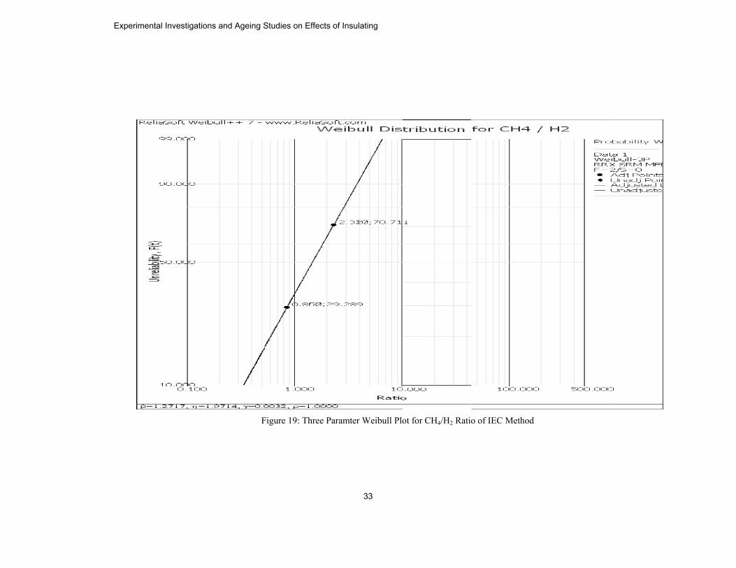
FFigure 19: Three Paaramter Weibull Plo
ot for CH4/H2 Ratioo of IEC Method
Experimental Investigations and Ageing Studies on Effects of Insulating
33

Figgure 20. Three Paraamter Weibull Plott for C2H4/C2H6 Rattio of IEC Method
S. Venkatesh, et al.
34

Figure 21. We
eibull Plot for Num mber of HFHV Imppulse Shots
Experimental Investigations and Ageing Studies on Effects of Insulating
35

Table 7 indicates the analysis describing the unreliability percentages for various gases for increasing number of HFHV shots carried out during studies.
Table 7. Analysis of Two Parameter Weibull Distribution for Oil - Normal and Sample - 3
Table 8. Analysis of Three Parameter Weibull Distribution for Oil- Normal & Sample-3
It is inferred from the reliability studies carried out using Weibull distribution characterization that the transformer oil degradation starts substantially after five pulses of HFHV at 89.7 kHz. If it is assumed that the simulated high frequency overvoltages are rare in occurrence (since they are usually internal faults such as ferroresonance) it may be construed that two HFHV pulses are likely to occur in a month. Thus the ageing of the transformer oil under study indicates safe use for about 3 months. 7. Conclusions The following salient aspects are observed and inferred during the detailed studies: 1. The influence of stressed volume theory explains the increase in breakdown voltage at the
instant of breakdown of barrier which created a pinhole. This theory is also explained in terms of Double Electric Layer mechanism. The experimental results substantiate this interaction of interface with oil.
2. The barrier influence is maximum when the barrier is at about 25% of the gap from the HV electrode in an inhomogeneous field.
3. Experimental results indicate an increased breakdown voltage characteristic for HFHV oscillations irrespective of the values of frequencies for barrier position near the HV electrode.
4. It is also evident from sample studies that the breakdown strength is not influenced to a large extent if the barrier is positioned near the LV electrode.
No. of shots Unreliability in % C2H2/C2H4 CH4/H2 C2H4/C2H6 1 29.289 0.42 0.86 0.80 3 38 0.85 1.2 1.8 5 42 1.2 1.3 2.4
20 55 2.6 1.7 6.5 40 62 4 1.9 11 60 67 5.5 2.2 17 80 69 6 2.25 18
100 70.711 6.54 2.32 19.11 120 72 7.5 2.5 22 140 74 7.8 2.7 24
No. of Shots Unreliability in % C2H2/C2H4 CH4/H2 C2H4/C2H6 1 29.289 0.42 0.86 0.80 3 38 0.85 1.2 1.8 5 42 1.2 1.3 2.4
20 55 2.6 1.7 6.5 40 62 4 1.9 11 60 67 5.5 2.2 17 80 69 6 2.25 18
100 70.711 6.54 2.32 19.11 120 72 7.5 2.5 22 140 74 7.8 2.7 24
S. Venkatesh, et al.
36

5. It is evident from the case studies based on Roger’s Ratio and IEC Ratio methods that barriers with small airgaps in oil led to breakdown voltages at high temperatures with subsequent to continuous arcing. Indications of high temperature arcing were substantiated by increased values of acetylene.
6. It is also pertinent to note that dissolved content of carbon dioxide was not substantial since the degradation of oil-barrier composite occurred at high temperatures. This fact is diagnosed and cross verifies the claim made by researchers who have carried out diagnosis on insulation condition of transformer oil [16] Thus it can be concluded that arcing faults at high temperatures lead to thermal degradation of oil without participation of degradation of cellulose.
7. It is also inferred from the reliability studies carried out using Weibull distribution characterization that the transformer oil degradation starts substantially after five pulses of HFHV at 89.7 kHz. If it is assumed that the simulated high frequency overvoltages are rare in occurrence (since they are usually internal faults such as ferroresonance) it may be construed that two HFHV pulses are likely to occur in a month. Thus the ageing of the transformer oil under study indicates safe use for about 3 months.
Acknowledgement The authors of this work are extremely grateful to Prof. R.Sethuraman, Vice- Chancellor, SASTRA University, Dr. S. Vaidhyasubramaniam, Dean - Planning and Development, SASTRA University and Dr. S. Swaminathan, Dean - Sponsored Research and Director - CeNTAB, SASTRA University for the support and motivation extended to them during the course of the research. The authors are also grateful to Dr. B. Viswanathan, Dean/SEEE, SASTRA University for many useful suggestions, discussion and motivation. References [1] Van Craenenbroeck T, De Herdt H, De Ceuster J, Marly J P, Van Dommelen D, Belmans
R, “Detailed Study of Fast Transient Phenomena in Transformers and Substations Leading to an Improved System Design”, Proceedings of 15th CIRED, 1.12, pp. 1-6, 1999.
[2] C57.142-2010, "IEEE Guide to Describe the Occurrence and Mitigation of Switching Transients Induced by Transformers, Switching Device, and System Interaction", 2010.
[3] Chaurasia, M P, "High Voltage Engineering", Khanna Publishers, 2nd edition, 2000. [4] Lebedev S M, Gefle O S, “On the Barrier Effect Mechanism in Inhomogeneous
Dielectrics”, International Conference on Solid Dielectrics, Toulouse, France, 2004. [5] Kara A, Onal E, Kalenderli O, Mardikyan K, “The Effect of Insulating Barriers on AC
Breakdown Voltage in Inhomogeneous Field”, IEEE MELECON, May 16 – 19, Benalmadena (Malaga), Spain, 2006.
[6] Nakao, Y.; Naruse, M.; Suzuki, Y.; Itoh, H.; Sakai, Y.; Tagashira, H., "Influence of sort and thickness of insulating barriers on the positive impulse creepage discharge in transformer oil", 12th International Conference on Conduction and Breakdown in Dielectric Liquids, Vol.15 Issue 19, 316-319, 1996.
[7] Nagel, M.; Leibfried, T., "Investigation on the high frequency, high voltage insulation properties of mineral transformer-oil", IEEE Conference on Electrical Insulation and Dielectric Phenomena, Vol.15 Issue 18, 226-228, 2006.
[8] Sarathi, R. Karri, C.S., 1997, "Effect of barrier in short air gaps under oscillatory impulse voltages", IEEE Conference on Electrical Insulation and Dielectric Phenomena, Vol.2, 731-734.
[9] Nakao, Y.; Naruse, M.; Suzuki, Y.; Itoh, H.; Sakai, Y.; Tagashira, H., "Influence of insulating barrier on the creepage discharge in transformer oil", IEEE Transactions on Dielectrics and Electrical Insulation, Vol. 4 No.6, pp. 775-779, 1997.
Experimental Investigations and Ageing Studies on Effects of Insulating
37

[10] VenTunDiel
[11] VanDomDist
[12] C57Tran
Assistant ElectricalpublicatiosuccessfuHe is alsoinclude PRecognitiInsulation
of IEEE a
nkatesh S, Rajed Circuit Applectric Materia
n Craenenbroemmelen D, “Extribution Trans.104.1991, I.,
nsformer”, 199
S. VeEnginTechnLater EnginPatternAlstomManag
Professor in l and Electronons to his crully completed o a reviewer inPartial Discharion and Artifin Society and S
M. BElectrMasteresearVoltagAgeinfacultyEngin
and IEEE Powe
esh R, Karthiproach”, 8th Intals, pp. 380 – 3ck T, De Cexperimental anformers”, Proc“IEEE Guide
92, The Institute
enkatesh obtaineering from Anology-High V
he received hneering specialn Recognitionm Limited, Sysger- Engineerthe Departmenics Engineerinedit in Interna Research &
n leading Internrge, Substationcial Intelligen
Smart Grid Com
Balasubramanronics Engineerer Degree in Prch interest incge Testing Tec
ng Characterizay and researeering, SASTRer & Energy So
keyan B, Saraternational Co83, 2006 .
euster J, Marlnd Numerical c. IEEE/PES Wfor Interpreta
e of Electrical
ined his BachAnnamalai UnivVoltage Enginehis Ph.D. fromlizing in the fin Using Modulstems Group-Inring & Qualitnt of Electricang, SASTRA Unational Journ
Modernizationnational Journn Engineeringce. He is an mmunity.
nian received ring from Bha
Power Systemscludes Conditiochniques, Highation of Electrrch scholar iRA University,ociety.
avanan S, “Dinference on Pr
ly J P, De HAnalysis of F
Winter Meetingation of Gases
and Electronic
helor Degree inversity, India ineering from SAm SASTRA U
field of Multiplar Neural Netndia, T & D Prty Assurance. al and ElectronUniversity, Indals and Confn Fund (R & M
nal publishers. g & EHV Traactive membe
his Bachelorarathidasan Unis from SASTRon Assessmen
h Voltage Tranrical Insulationin School of, Thanjavur, In
ielectric Integrroperties and a
Herdt H, BrouFast Transient g, Singapore, 20
Generated in c Engineers.
n Electrical ann 1994 and MaASTRA UniveUniversity in ple Source Partworks. He warojects Divisio
He is presenics Engineeridia. He has seferences of reMF) project in His specific aransmission syer of IEEE, IE
r Degree in iversity in the RA University
nt of Power Apnsients in Powen System. Pref Electrical &ndia. He is an a
rity Test - Aapplications of
uwers B, VanPhenomena in000. Oil-Immersed
nd Electronicsaster Degree inersity in 2004High Voltage
rtial Dischargeas earlier with
on, as Assistantently a Senioring, School ofeveral researchepute. He hasthe year 2011
reas of intereststems, Pattern
EEE Dielectric
Electrical andyear 2002 and
y in 2006. Hispparatus, Higher Systems andsently, he is a& Electronicsactive member
A f
n n
d
s n . e e h t r f h s . t n c
d d s h d a s r
S. Venkatesh, et al.
38