experimental investigation of polymer flooding with low ...hths carbonate reservoir cores. materials...
TRANSCRIPT

Vol.:(0123456789)1 3
Journal of Petroleum Exploration and Production Technology (2019) 9:1517–1530 https://doi.org/10.1007/s13202-018-0563-z
ORIGINAL PAPER - PRODUCTION ENGINEERING
Experimental investigation of polymer flooding with low-salinity preconditioning of high temperature–high-salinity carbonate reservoir
Umar Alfazazi1 · Waleed AlAmeri1 · Muhammad R. Hashmet2
Received: 10 May 2018 / Accepted: 5 October 2018 / Published online: 12 October 2018 © The Author(s) 2018
AbstractApplication of polymer flooding in high temperature–high salinity (HTHS) carbonate reservoirs is challenging due to lack of polymers that can withstand such harsh reservoir conditions. The traditional polymers are usually sensitive to high salin-ity, especially at high temperature. However, injection of low-salinity make-up brines may precondition high-salinity res-ervoirs before initiating polymer flooding which may reduce chemical degradation of polymer. This study aims to evaluate the effectiveness of a partially hydrolyzed polyacrylamide base polymer for mobility control application in a low-salinity preconditioned carbonate reservoir and hence on the improvement of oil recovery at HTHS carbonate reservoir. Core flood-ing experiments using unsteady-state technique were conducted on reservoir cores with permeability range of 10–100 mD. During each experiments, salinity of the make-up brines were changed to study the effect of preflush salinity and polymer flooding in HTHS reservoir. Oil production from water flooding for all the cases was found to be between 49 and 65%. Polymer helped to reduce the mobility ratio from 4.1 to less than 1 and additional 7–11% of oil was recovered from the remaining oil saturation after water flooding. Comparisons were also made between oil recovery results based on volumetric production and in situ saturation monitoring (ISSM) data, which were found to be matching. Additionally, the ISSM helped to understand the performances of fluids injected during oil recovery stages and captured front movement of the fluids at all time. Also, high capillary end effect was confirmed from the ISSM which may lead to underestimation of the oil recovery from water flooding in the absence of ISSM. Resistance factor and residual resistance factor were also calculated during all core flooding experiments and were found to be 7.0, 2.4, 36 and 3.7, 1.4, 8.9, respectively.
Keywords Polymer flooding · HPAM · IOR · X-ray scanning · In situ saturation monitoring · Carbonate reservoir · HTHS · Low salinity water flooding
AbbreviationsATBS Acrylamido-tert-butyl-sulfonateBP Back pressureCc Cubic centimeterExp. ExperimentFW Formation waterHTHS High temperature high salinityHPAM Partially hydrolyzed polyacrylamideIOR Improved oil recoveryISSM In situ saturation monitoring
k Permeability (mD)kabs Absolute permeabilityL Length (cm)Mw Molecular weightmD MiliDarcyNVP n-vinyl-pyrrolidoneOOIP Original oil in placePV Pore volume (cc)Q Flow rate (cc/min)RF Resistance factorRRF Residual resistance factorSW SeawaterSwi Initial water saturation (%)Sor Residual oil saturationVp Volume produced (cc)0.5*SW 2 times diluted seawater0.25*SW 4 times diluted seawater
* Muhammad R. Hashmet [email protected]
1 Khalifa University of Science and Technology, P.O. Box 2533, Abu Dhabi, United Arab Emirates
2 Nazarbayev University, Astana, Kazakhstan

1518 Journal of Petroleum Exploration and Production Technology (2019) 9:1517–1530
1 3
µ Viscosity (cP)ΔP Differential pressure (psi)ρ Density (g/cc)
Introduction
Polymer flooding is considered as one of the most successful IOR techniques with over 40 years of application, both in lab and field scale. The main objective of polymer flooding is to increase the viscosity of injection water to improve mobility ratio of oil and water (Samanta et al. 2010). This is achieved by addition of water soluble polymers to the injection water (Gaillard et al. 2014; Salmo et al. 2017). In most cases, an unfavorable mobility ratio exists in the reservoir during water flooding due to the high viscosity of oil compared to water. This results in high water production (Khorsandi et al. 2016) whereas a significant portion of the oil is left within the pores (Zhang et al. 2011). Previous studies (Algharaib et al. 2014) have shown that polymer flooding technique can improve oil recovery by 10–15% from remaining oil satura-tion after water flooding.
Most of the field applications where polymer flooding is practiced are sandstone reservoirs. The temperature of such reservoirs usually does not exceed 65 °C (Delaplace et al. 2013; Wang et al. 2008). Hence, its application beyond this temperature becomes difficult (Gao 2013) due to the unavailability of polymers that withstands such conditions. This complexity increases especially in carbonate reser-voirs. Although, polymer flooding is believed to have the potential to improve oil recovery from carbonate reservoirs based on the current ongoing research (Bennetzen et al. 2014; Gaillard et al. 2014; Quadri et al. 2015; Vermolen et al. 2011). The complex nature of carbonate reservoirs as well as their high formation water salinity and high tempera-ture (~ 170,000 ppm and ~ 120 °C), especially in the Middle Eastern region, makes it difficult to find suitable polymer candidates to implement this IOR technique. In addition, performance of polymer flooding is majorly dependent on reservoir heterogeneity, salinity, temperature, permeability and its compatibility with other chemicals use for oil recov-ery (Almansour et al. 2017; Hashmet et al. 2017a; Sheng 2017).
There are mainly two types of polymers used for oil recovery purposes: synthetic partially hydrolyzed poly-acrylamide HPAM (and its derivatives) and biopolymer such as Xanthan (Sheng et al. 2015). HPAMs are the most widely used polymers for IOR applications compared to the biopolymers (Samanta et al. 2010; Sorbie 2013). However, these polymers tends to degrade or hydrolyze under harsh conditions especially in the presence of high salinity (Green and Willhite 1998). On the other hand, Xanthan biopoly-mer is capable of resisting very high salinity conditions
(Cannella et al. 1988; Sheng et al. 2015). The main prob-lems associated with this polymer is poor injectivity and biodegradation which makes the HPAMs more preferable for IOR applications (Hashmet et al. 2017a; Seright et al. 2011; Unsal et al. 2018; Zaitoun et al. 2012). Although, the viscosifying properties of all HPAM base polymers strongly depend on brine salinity given their polyelectrolyte character (Khorsandi et al. 2017; Nasr-El-Din and Taylor 1996). In severe conditions, especially in the cases of carbonate res-ervoirs, use of more robust polymers are necessary to ensure the stability of the polymers in reservoirs for a long period (Gaillard et al. 2015; Han et al. 2012).
In recent years, efforts have been made by researchers to discover new types of polymers that can withstand HTHS (Bennetzen et al. 2014; Gaillard et al. 2015; Leblanc et al. 2015; Levitt et al. 2013). This development was achieved by the incorporation of some specific monomers such as acrylamido-tert-butyl-sulfonate (ATBS) or N-vinyl-pyrro-lidone (NVP) to the backbone chain of the polymers thereby, adding more stability (by limiting hydrolysis) and robustness to the polymer especially at high temperature (Vermolen et al. 2011). Depending on the level of these monomers at the polymer backbone chain, such polymers can withstand very high salinity and high temperature (Gaillard et al. 2014; Vermolen et al. 2011).
The effectiveness of these types of polymers can be fur-ther enhanced by preconditioning the reservoir through injection of low-salinity brines (preflush) before polymer flooding, thus reducing chemical degradation. In addi-tion, viscosity of HPAM base polymers always increases as the salinity of the water is lowered which is caused by the polymer expansion and electrostatic repulsion (Unsal et al. 2018; Vermolen et al. 2014; Wever et al. 2011). This also means that lower concentration of polymer would be required to reach a target viscosity compared to when the polymer is prepared in high salinity brine (Algharaib et al. 2014; Vermolen et al. 2014). Also, injection of low-salinity brines before polymer flooding could also lead to additional oil recovery by changing the rock wettability to a more water-wet condition (Almansour et al. 2017; RezaeiDoust et al. 2011; Shaker and Skauge 2013), although, its suc-cess strongly depends on rock mineralogy as well as fluid properties.
Algharaib et al. (2014) investigated the effect of poly-mer concentration on the performance of polymer flood-ing in high salinity reservoirs. They reported that there are limits of concentration above which polymer performance decreases. They also studied the effect of polymer slug size on oil recovery which they concluded that for each forma-tion or reservoir conditions, there is an optimum slug size and concentration required for polymer flooding. In addition, they found out that at high salinity, the performance of the polymer reduces. Similar experiments were also conducted

1519Journal of Petroleum Exploration and Production Technology (2019) 9:1517–1530
1 3
to study polymers for chemical flooding in carbonate reser-voirs characterized with high salinity and high temperature. The target of the study was a representative carbonate reser-voir in the Middle East. Finally, they reported that an addi-tional oil recovery by polymer flooding was about 11% with a 3000 ppm sulfonated polyacrylamide which was injected at the tertiary recovery stage and under reservoir conditions (Han et al. 2014).
In this study, an NVP-HPAM base polymer (SAV10) was used to conduct oil recovery experiments. It is a terpolymer made of N-vinyl-pyrrolidone (NVP) which gives it ability to resist high temperature and salinity. In addition, oil recovery studies were carried out on a linear X-ray core flood system which helps in monitoring the in situ fluids saturation in addition to the pressure and volumetric production data. The linear X-ray data were automatically recorded by the system in terms of counts along the core length and later converted to saturations. This is an advanced technology that gives bet-ter understanding of fluids performances as well as level of capillary end effect. Core flood experiments were also con-ducted by Hashmet et al. (2017b) to study the effectiveness of a HPAM base polymer on oil recovery in HTHS carbonate reservoirs. Results of the experiments showed that the poly-mer was effective in enhancing the mobility ratio and was able to produce more oil (Hashmet et al. 2017b). The experi-ments were conducted with the aid of a linear X-ray core flood system to record the ISSM data. They concluded that the ISSM data helped in understanding the fluids efficiency, as well as fluid distribution along the core. In this study, the impact of low-salinity polymer flooding is investigated on HTHS carbonate reservoir cores.
Materials and methods
Materials used in this study include four synthetic brines, high viscosity lab oil (Primol 352), crude oil, 1-iododecane, SAV10 polymer, and three carbonate reservoir cores sam-ples from a Middle Eastern field. The brines were prepared in the lab by mixing exact amount of salts with deionized water. They include formation water (FW), seawater (SW), 2 times diluted seawater (0.5*SW), and 4 times diluted sea-water (0.25*SW). FW of 167,000 ppm salinity was prepared based on the composition of the target reservoir. While SW with salinity of 39,000 ppm was prepared based on the sea-water salt composition. Finally, 0.5*SW (19,500 ppm) and 0.25*SW (9750 ppm) were prepared by simple dilution of SW with deionized water twice and four times respectively. Table 1 provides the composition of brines used in this study. Due to the presence of water molecules in CaCl2 and MgCl2, a calculated amount of the same salts was added to the brines to compensate for the water molecules.
High viscosity lab oil was used to reach reservoir rep-resentative initial water saturation, Swi before switching to crude oil. The crude oil was initially filtered with a filter paper (0.45 μL) to remove asphaltenes and unwanted solid deposits before usage. SAV10 which is HPAM base polymer was used for conducting this study and was provided by SNF FLOERGER in powder form. The molecular weight (Mw) of the polymer was reported to be 2–4 million Daltons. In addition, the polymer solutions were prepared in accordance with the API standards for polymer preparation (API R 63 1990). All solutions were prepared in the glove box so as to maintain minimum oxygen level (0.5 ppm) in the solu-tions. Initially, the prepared brines were transferred into the glove box and stirred for 30 min to get rid of oxygen in the brines. Then, the brines were stirred on a magnetic stirrer at high speed of 300 rpm with the vortex extending to about 70%. The polymer powder was then sprinkled gently on the shoulder of the vortex to avoid agglomeration of polymer. The speed of the stirrer was reduced to 100 rpm after 10 min of fast stirring to avoid mechanical degradation. Finally, the solutions were left overnight on the stirrer to completely homogenize.
Three reservoir core samples with diameter of 3.8 cm each were used to conduct core flood experiments. Core plugs were first cleaned thoroughly with multiple solvents to remove reservoir crude oil and unwanted chemicals before usage. Then, basic routine core analysis which includes dry weight, porosity, permeability, and wet (saturated) weight measurements were conducted. Even though, the cores were all from the same field and similar depth, the permeabilities
Table 1 Composition of synthetic brines
Salts Formation water (FW) (g/L)
Seawater (SW) (g/L)
0.5*SW (g/L)
0.25*SW (g/L)
NaCl 134.61 24.80 12.40 6.20KCl 1.42 0.80 0.40 0.20CaCl2.2H2O 33.93 2.11 1.06 0.53MgCl2.6H2O 12.10 25.17 12.59 6.29
Table 2 Petrophysical properties of core samples used for oil recov-ery studies
Core ID Exp. 1 Exp. 2 Exp. 3
Length (cm) 7.34 6.96 7.06Porosity (%) 27.73 27.14 27.94Pore volume (cc) 23.45 22.69 22.72Air permeability (mD) 35.26 130.14 15.29Absolute permeability (mD) 27.00 94.00 10.00

1520 Journal of Petroleum Exploration and Production Technology (2019) 9:1517–1530
1 3
varies. Table 2 presents the petrophysical properties of core samples used in this study.
Core flooding experiments
Three sets of unsteady state core flood experiments were conducted to evaluate the impact of water flood and poly-mer on oil recovery at reservoir condition (high temperature, pressure, and salinity). In addition to the pressure and volu-metric production data, the core flood equipment (shown in Fig. 1) is also coupled with linear X-ray which helps in monitoring the in situ saturation profiles in real time. The system automatically records its data in counts and can be converted to real-time in situ saturations with the aid of a simple formula (Eq. 1). The core flood system consists mainly of a core holder, three fluid accumulators, injection pumps, and pressure transducers. In addition, a computer is also connected to the equipment and is used for monitoring and recording parameters such as temperature, flow rates, pressures, and counts.
It is important to note that, one of the injected fluids is required to be doped (this could be either brine or oil) to dif-ferentiate the fluids calibrations in the linear X-ray data. As such, the doped fluid shows lesser counts while the undoped fluid shows higher counts. However, without doping one of the phases, the fluids show the same trend and hence it becomes difficult to understand the performance of each
(1)Saturation =log(selected scan) − log(100% oil)
log(100% water) − log(100% oil)
fluid during the injection process. In this study, crude oil was doped by adding 10% of 1-iododecane to the crude oil. To capture the complete saturation profile during both drainage and imbibition, it is necessary to follow certain procedure.
First, a clean-dry core plug is 100% saturated (by vacuum) with the doped crude oil and later flooded in the core flood system at reservoir temperature and pressure. Several X-ray scans are recorded to represent 100% oil saturation. The core is then re-cleaned with solvents and dried by following the standard procedure. The core is then saturated with FW to determine brine absolute permeability and scan to represent 100% water saturation. Absolute permeability is determined by injecting formation brine at different flow rates. Based on the differential pressures at each flow rate, absolute permeability is calculated from Darcy’s law as shown in (Eq. 2). Drainage experiment is then initiated to reach initial water saturation Swi. Similarly, several scans are recorded, the last scan is consid-ered as the Swi. To reach Swi, Primol followed by crude oil are injected at different flow rates until water production from the core is negligible and steady state conditions are achieved. Swi is calculated with the help of (Eq. 3). The core is then aged for 1 month to restore reservoir conditions and wettability (Shaker and Skauge 2013). Oil effective permeability is re-calculated after ageing and to account for any change in Swi. Imbibition is then initiated afterwards by injecting brine(s) followed by polymer (in accordance with the injection scenarios). In the process, X-ray scan is constantly monitoring the fluids satura-tions as fluids injection and displacement is taking place. It is important to state that, the above steps and experiments are all conducted at 120 °C and back pressure (BP) of 750 psi to mimic the reservoir conditions. To summarize the procedures
Fig. 1 Schematic of linear X-ray core flood equipment (LXRCF) used for conducting core flood experiments

1521Journal of Petroleum Exploration and Production Technology (2019) 9:1517–1530
1 3
described above, each core flooding experiment is made up of six phases and these are shown in Fig. 2.
The following injection scenarios were followed during the core flood experiments: seawater was initially injected in all the three core floods until steady state conditions were achieved during water flooding. Then, in 1st core flooding (Exp. 1), polymer flooding was initiated immediately after SW flooding and was followed by SW postflush. In the 2nd experiment (Exp. 2), 0.5*SW was injected after SW flood-ing and prior to polymer flooding to evaluate the effect of low-salinity water flooding preflush on oil recovery. While in the 3rd core flooding experiment (Exp. 3), 0.25*SW was injected after SW flooding, later followed by polymer flood-ing and post flush. During polymer flooding and postflush, major parameters such as resistance factor (RF) and residual resistance factor (RRF), are calculated from the following equations respectively
(2)kabs =14700 ∗ � ∗ Q ∗ L
A ∗ ΔP
(3)Swi =
(
1 −Vp
PV
)
× 100%
(4)RF =
(
k
�
)
brine(
k
�
)
polymer
=ΔPpolymer
ΔPbrine
Results and discussions
Fluids properties
Viscosity and density measurements of fluids were done with the aid of viscometer and densitometer. Table 3 enlists the properties of the fluids used at different tem-peratures. As for the polymer solutions, three solutions were prepared based on the injection scenarios. In the 1st core flood, the polymer was prepared in SW because the same brine was used during preflush. Likewise, in the 2nd and 3rd core flood experiment, the polymers were prepared in 0.5*SW and 0.25*SW, respectively.
Polymer concentration was considered during polymer preparation to control the viscosity at the experimental condition. The condition was that; the polymer solutions should have viscosity close to the oil viscosity (1.2 cP) at 120 °C from the rheometer. Based on the series of rhe-ological tests carried out, 3000 ppm was selected as the optimum concentration for the core flooding. The rheology measurements were conducted with the aid of a stress con-trolled shear rheometer HR-3 (by Anton Paar). In addition,
(5)RRF =
(
k
�
)
brine preflush(
k
�
)
brine post flush
=ΔPbrine postflush
ΔPbrine preflush
Fig. 2 Core flood procedure for oil recovery studies Oil Flooding
•X-ray scan representing 100% oil saturation
Water Flooding•Measure Abs. Perm. and X-ray scan at 100% water saturation
Oil Flooding•To reach Swi + X-ray scan representing Swi
Water Flooding (Preflush)•To reach Sor + monitor saturation at each flow rate
Polymer Flooding•To improve mobillity ratio
Water flood (postflush)•Calculate permeability reduction factor
Table 3 Density and viscosity measurements of fluids at different temperatures
Brines Density, ρ (g/cc) Viscosity, µ (cP)
T = 20 °C T = 60 °C T = 120 °C T = 20 °C T = 60 °C T = 120 °C
FW 1.11 1.09 1.01 1.69 0.82 0.45SW 1.02 1.01 0.84 1.12 0.72 0.400.5*SW 1.01 0.99 0.82 1.10 0.72 0.380.25*SW 1.01 0.99 0.79 1.04 0.70 0.37Doped primol 0.88 0.87 0.83 62.05 19.14 4.58Doped crude oil 0.87 0.85 0.81 5.99 2.94 1.20

1522 Journal of Petroleum Exploration and Production Technology (2019) 9:1517–1530
1 3
measurements were conducted at a constant shear rate of 10 s− 1 and temperature ramp from 25 to 120 °C. At 120 °C, the viscosity of the polymer in SW, 0.5*SW, and 0.25*SW brines were measured as 0.95, 1.09, 1.10 cP, respectively.
Core flooding results
Core flooding experiment 1 (Exp. 1)
As mentioned previously, the core was initially saturated with crude oil to get the 100% oil scan. The average X-ray counts recorded along the length of the core for complete oil satu-rated core was 33,876. After re-cleaning the core, absolute permeability was measured by injecting FW at different flow rates and was calculated as 27 mD. The average counts from X-ray along the length of core for 100% water-saturated core was 62,828. Drainage was then initiated and Swi was calcu-lated as 11.71%. Also, the average counts from the X-ray at Swi was 36,507.
Seawater flooding was then initiated for 23 h at different flow rates (with 0.2 cc/min set as the base flow rate) until steady state conditions were achieved and oil production was negligible. The oil production was continuously monitored throughout seawater flooding. Interestingly, an early water breakthrough occurred after 14.5% production of OOIP (exactly after 15 min of SW flooding at 0.2 cc/min). This process was fully captured with the help of the ISSM. The early water breakthrough could be as a result of high mobil-ity ratio (calculated as 3.66) which was caused by the large difference in viscosity between the two phase fluids. Also, high permeability channels are expected to have contributed in the early breakthrough, where the injected water follows the easiest paths. Both these factors are common features of carbonate reservoirs.
At the end of seawater flooding, the total oil recovery was calculated to be 51%. Polymer flooding was then initiated afterwards. The viscosity of the polymer solution was 1.2
cP (from bulk rheology) at 120 °C. Polymer was injected for 16 h repeating the same flow rates used during water flood-ing. Polymer flooding helped to improve the mobility ratio to 0.56 and recovered 11% additional oil from the remain-ing oil saturation after water flood. However, no additional recovery was recorded during postflush. Figure 3 shows the differential pressure and production (based on volumetric data) from both seawater and polymer flooding.
Based on the differential pressure recorded during polymer flooding and at the end of postflush, resistance factor RF and residual resistance factor RRF were calculated respectively. It can be seen that due to relatively high viscosity of polymer compared to the seawater and also the retention property of polymers on rocks (Agi et al. 2018), the pressure during poly-mer flooding is high resulting in high resistance factor values (3.72). Figure 4 shows resistance RF and residual resistance factor RRF data as function of flow rates. It was observed that the Resistance factor increases with increasing flow rate, as well as in situ shear rates during polymer flood. The resist-ance factor at flow rates of 0.2, 0.5, 1.0, and 2.0 (which cor-responds with apparent shear rates of 5, 12, 24, and 47 1/s) were calculated as 1.8, 2.2, 4.5, and 7.0 respectively. In addi-tion, the effective in situ viscosity during polymer flooding was calculated and was found to be increasing with increas-ing flow rates (thus, shear thickening behavior). Such behav-ior is expected above certain critical shear rate as reported by (Seright et al. 2011). This behavior is known as a shear thick-ening or viscoelastic behavior which is encountered during the injection of HPAM base polymers in porous media (Wei et al. 2014). Research have shown that the elastic properties of such polymers may also reduce the residual oil saturation (Sheng et al. 2015; Vermolen et al. 2011; Wang et al. 2008; Wei et al. 2014). However, this study is out of our scope. As for the residual resistance factor, it was observed that there was a slight decrease with increasing flow rates which can be attrib-uted to decrease in the mechanical entrapment as flow rate is increased during postflush water flooding (AlSofi et al. 2017).
Fig. 3 Oil recovery factor (%) and differential pressure as a function of PV injected during oil recovery of Exp.1

1523Journal of Petroleum Exploration and Production Technology (2019) 9:1517–1530
1 3
The apparent shear rate and in situ polymer viscosity were calculated based on the method suggested by (Zaitoun and Kohler 1988). Table 4 summarizes the key results from Exp. 1.
Based on the ISSM data from the X-ray scans, Fig. 5 shows the complete change in saturation profiles during oil recovery. It showed that water breakthrough has occurred relatively early (the average water saturation at the time
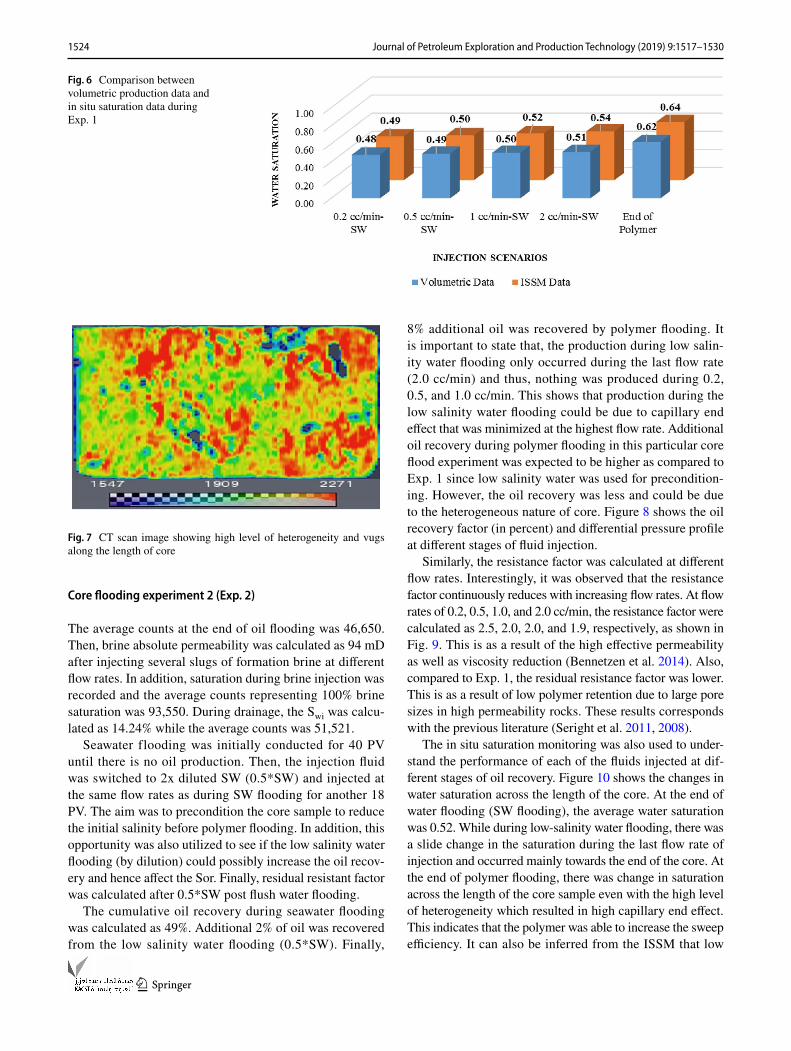
of breakthrough was 0.19) which corresponds with the volumetric production data. It also shows that during poly-mer flooding, the polymer was able to control the mobility ratio and hence increased the sweep efficiency along the length of core. The polymer is promising even with the level of heterogeneity that exist in the core. Comparison was also made between the volumetric production data and the ISSM data to quantify the accuracy of both results. The values appears to be close with difference less than 5% as shown in Fig. 6. The cumulative oil recovery from volu-metric production and in situ saturation was 62% and 64%, respectively. This margin error is expected from the labo-ratory data and could be as a result of inaccuracy when taking manual readings (Hashmet et al. 2017b).
The core plug was later CT scanned at residual oil satu-ration to see the amount of oil left in the core. Figure 7 is the image from the CT scanning. The color variation represents CT numbers in which red color indicates high density which include remaining oil and the rock. Less CT number is representing the water.
Fig. 4 RF and RRF data as function of flow rates in cc/min during Exp.1
Table 4 Summary of major results from first core flooding experi-ment
Core ID Exp.1
Mobility ratio during WF 3.66Mobility ratio during PF 0.56Resistance factor RF at 2.0 cc/min 7.02Residual resistance factor RRF at 2.0 cc/min 3.72Water flooding oil recovery (%) 51Additional oil recovery due to polymer (%) 11Total oil recovery (%) 62
Fig. 5 ISSM profile with respect to fluid injected along the core length during Exp.1
1524 Journal of Petroleum Exploration and Production Technology (2019) 9:1517–1530
1 3
Core flooding experiment 2 (Exp. 2)
The average counts at the end of oil flooding was 46,650. Then, brine absolute permeability was calculated as 94 mD after injecting several slugs of formation brine at different flow rates. In addition, saturation during brine injection was recorded and the average counts representing 100% brine saturation was 93,550. During drainage, the Swi was calcu-lated as 14.24% while the average counts was 51,521.
Seawater flooding was initially conducted for 40 PV until there is no oil production. Then, the injection fluid was switched to 2x diluted SW (0.5*SW) and injected at the same flow rates as during SW flooding for another 18 PV. The aim was to precondition the core sample to reduce the initial salinity before polymer flooding. In addition, this opportunity was also utilized to see if the low salinity water flooding (by dilution) could possibly increase the oil recov-ery and hence affect the Sor. Finally, residual resistant factor was calculated after 0.5*SW post flush water flooding.
The cumulative oil recovery during seawater flooding was calculated as 49%. Additional 2% of oil was recovered from the low salinity water flooding (0.5*SW). Finally,
8% additional oil was recovered by polymer flooding. It is important to state that, the production during low salin-ity water flooding only occurred during the last flow rate (2.0 cc/min) and thus, nothing was produced during 0.2, 0.5, and 1.0 cc/min. This shows that production during the low salinity water flooding could be due to capillary end effect that was minimized at the highest flow rate. Additional oil recovery during polymer flooding in this particular core flood experiment was expected to be higher as compared to Exp. 1 since low salinity water was used for precondition-ing. However, the oil recovery was less and could be due to the heterogeneous nature of core. Figure 8 shows the oil recovery factor (in percent) and differential pressure profile at different stages of fluid injection.
Similarly, the resistance factor was calculated at different flow rates. Interestingly, it was observed that the resistance factor continuously reduces with increasing flow rates. At flow rates of 0.2, 0.5, 1.0, and 2.0 cc/min, the resistance factor were calculated as 2.5, 2.0, 2.0, and 1.9, respectively, as shown in Fig. 9. This is as a result of the high effective permeability as well as viscosity reduction (Bennetzen et al. 2014). Also, compared to Exp. 1, the residual resistance factor was lower. This is as a result of low polymer retention due to large pore sizes in high permeability rocks. These results corresponds with the previous literature (Seright et al. 2011, 2008).
The in situ saturation monitoring was also used to under-stand the performance of each of the fluids injected at dif-ferent stages of oil recovery. Figure 10 shows the changes in water saturation across the length of the core. At the end of water flooding (SW flooding), the average water saturation was 0.52. While during low-salinity water flooding, there was a slide change in the saturation during the last flow rate of injection and occurred mainly towards the end of the core. At the end of polymer flooding, there was change in saturation across the length of the core sample even with the high level of heterogeneity which resulted in high capillary end effect. This indicates that the polymer was able to increase the sweep efficiency. It can also be inferred from the ISSM that low
Fig. 6 Comparison between volumetric production data and in situ saturation data during Exp. 1
Fig. 7 CT scan image showing high level of heterogeneity and vugs along the length of core

1525Journal of Petroleum Exploration and Production Technology (2019) 9:1517–1530
1 3
Fig. 8 Oil recovery factor (%) and differential pressure vs PV injected during oil recovery of Exp. 2
Fig. 9 RF and RRF data as a function of flow rates in cc/min during Exp. 2
Fig. 10 ISSM profile across the core length showing the changes in water saturation during oil recovery of Exp. 2

1526 Journal of Petroleum Exploration and Production Technology (2019) 9:1517–1530
1 3
salinity water flooding only minimized the capillary end effect as a result of the high flow rate. The in situ saturation moni-toring profiles correlates with the volumetric production data as well as CT image (Fig. 12) which shows poor oil displace-ment along the core length due to high heterogeneity as well as vugs. Thus, lack of additional oil recovery during polymer flooding compared to Exp. 1 could be due to the heterogeneity and vugs in the core plug. Comparison between volumetric production data and ISSM was done and is shown in Fig. 11.
Table 5 summarizes the results from Exp. 2 experiment. Similarly, the core was CT scanned to have a clear image at residual oil saturation. As expected, significant amount of oil was left unswept in the core due to poor oil sweep and can be seen from Fig. 12.
Core flooding experiment 3 (Exp. 3)
The average counts at 100% oil saturation was 42,400. Brine absolute permeability and thus 100% water saturation scan was measured. The average counts at 100% brine saturation was 74,845. Finally, the scans representing Swi were taken
after ageing and was 45,630 and initial water saturation was calculated to be 12.31%.
Oil recovery was initiated after measuring oil effective permeability at post ageing stage. Initially, seawater was injected into the core for 20 h until no more oil production. Then, 0.25*SW was injected for about 7 h to precondition the core sample and to see if low salinity water flooding could recover more oil. Finally, 3,000 ppm of polymer in 0.25*SW was injected for another 7 h before switching to postflush water flooding.
With SW flooding, the cumulative oil recovery was 65%. After seawater was injected at different flow rates (from 0.2 to 2.0 cc/min), the fluid was switched to low salinity brine and additional 1.3% was recovered. The same flow rates were repeated during low salinity water flooding. Similarly, there was no production at the initial flow rates of 0.2, 0.5, and 1.0 cc/min. Thus, oil recovery from low salinity water flooding was produced during the 2.0 cc/min alone as shown in Fig. 13. These results are in accordance with the previ-ous literature who found that low-salinity water flooding could not recover additional oil after seawater flooding in strong water-wet cores (Shaker and Skauge 2013). Then, 9% additional oil was recovered during polymer flooding. Because of the low permeability, polymer was only injected at 0.2 cc/min to avoid core damage. High resistance factor
Fig. 11 Comparison between volumetric production data and in situ saturation monitoring during Exp. 2
Fig. 12 CT image showing the SOR, heterogeneity, and vugs in the core plug used for Exp. 2. High CT number indicating high density
Table 5 Summary of major parameters from the second core flooding experiment
Core ID Exp. 2
Mobility ratio during WF 2.21Mobility ration during PF 1.75Resistance factor RF at 2.0 cc/min 1.99Residual resistance factor at 2.0 cc/min 1.40Water flooding oil recovery (%) 51Additional oil recovery due to polymer (%) 8Total oil recovery (%) 59
1527Journal of Petroleum Exploration and Production Technology (2019) 9:1517–1530
1 3
(36.7 at 0.2 cc/min) and residual resistance factor (8.91) were observed during polymer flooding and postflush. This is as a result of the low permeability that might cause pore plugging due to the small pore size in the low permeability sample (Hashmet et al. 2017a). However, mechanical deg-radation of polymer was not observed based on the rheology analysis of the core flood effluents.
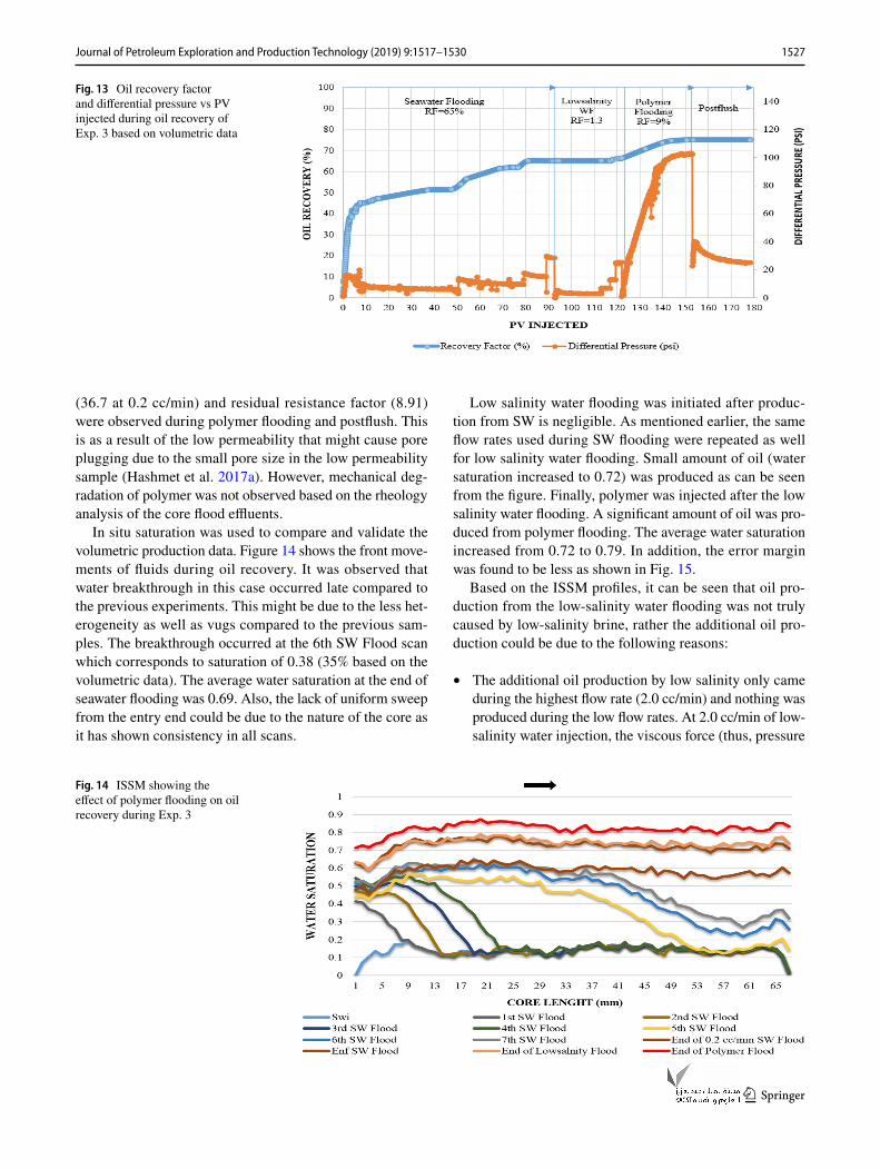
In situ saturation was used to compare and validate the volumetric production data. Figure 14 shows the front move-ments of fluids during oil recovery. It was observed that water breakthrough in this case occurred late compared to the previous experiments. This might be due to the less het-erogeneity as well as vugs compared to the previous sam-ples. The breakthrough occurred at the 6th SW Flood scan which corresponds to saturation of 0.38 (35% based on the volumetric data). The average water saturation at the end of seawater flooding was 0.69. Also, the lack of uniform sweep from the entry end could be due to the nature of the core as it has shown consistency in all scans.
Low salinity water flooding was initiated after produc-tion from SW is negligible. As mentioned earlier, the same flow rates used during SW flooding were repeated as well for low salinity water flooding. Small amount of oil (water saturation increased to 0.72) was produced as can be seen from the figure. Finally, polymer was injected after the low salinity water flooding. A significant amount of oil was pro-duced from polymer flooding. The average water saturation increased from 0.72 to 0.79. In addition, the error margin was found to be less as shown in Fig. 15.
Based on the ISSM profiles, it can be seen that oil pro-duction from the low-salinity water flooding was not truly caused by low-salinity brine, rather the additional oil pro-duction could be due to the following reasons:
• The additional oil production by low salinity only came during the highest flow rate (2.0 cc/min) and nothing was produced during the low flow rates. At 2.0 cc/min of low-salinity water injection, the viscous force (thus, pressure
Fig. 13 Oil recovery factor and differential pressure vs PV injected during oil recovery of Exp. 3 based on volumetric data
Fig. 14 ISSM showing the effect of polymer flooding on oil recovery during Exp. 3

1528 Journal of Petroleum Exploration and Production Technology (2019) 9:1517–1530
1 3
drop) is almost equal to that of SW injection at the same flow rate.
• It can be seen that the saturation profile during low-salin-ity water flooding only slightly changed in end part of the core (from 45 mm to end of the core). This also indicates that the production was due to capillary end effect that was minimized because of the high flow rate used at that particular time of injection.
• Polymer increased the oil recovery across the whole length of the core which means that the polymer was able to increase the sweep efficiency. The polymer was only injected at 0.2 cc/min because of high pressure drop due to low permeability of the core and retention occurrence
In summary, even as only 0.2 cc/min was during polymer flooding, an additional 9% of oil was recovered which was more as compared to the previous core floods. Hence, more oil could have been recovered at higher bump rates. The effectiveness of the polymer flooding was due to low salin-ity water preconditioning which resulted in higher solution viscosity and thus better mobility ratio reduction. Moreover, there was better oil sweep as compared to Exp. 2 as a result of less heterogeneity in the core plug. This was confirmed from both in situ saturation profiles and the CT image. CT scan image showed that the core is less vuggy compared to previous cores (Exp.1 and Exp.2) as can be seen from Fig. 16. Table 6 summarizes the main parameters and results from Exp. 3. As a result, there was better sweep of oil com-pared to previous experiments.
Conclusions
• Difficulties in the application of polymer flooding on HTHS reservoir can be overcome by injecting slugs of low-salinity brines before initiation of polymer flooding to precondition the high salinity.
• The polymer used in this study was successful in improv-ing the mobility ratio resulting in better sweep efficiency and hence producing more oil.
• It was found that, there was no significant oil production during low-salinity water flooding. The little production was due to capillary end effect that was minimized by the high flow rates. This was confirmed from the in situ saturation profiles. However, low salinity water flooding
Fig. 15 Comparison between volumetric production data and in situ saturation monitoring data during Exp. 3
Fig. 16 Scanned image of Exp. 3 at SOR showing heterogeneity and vugs along the core. The red color in the image represents high CT number and hence high density
Table 6 Summary of major results from third core flooding experi-ment
Core ID Exp. 3
Mobility ratio during WF 3.28Mobility ratio during PF 0.06Absolute brine permeability (md) 10Resistance factor at 0.2 cc/min 36Residual resistance factor 8.9Water flooding oil recovery (%) 66.3Additional oil recovery due to polymer (%) 9

1529Journal of Petroleum Exploration and Production Technology (2019) 9:1517–1530
1 3
resulted in the injection of polymer solutions with higher viscosities through preconditioning of the high-salinity formation.
• ISSM data from the linear X-ray confirmed the accuracy of the result during oil recovery. The difference between the volumetric production data and the ISSM is within 5%.
• ISSM data helped in identifying the heterogeneity level in the cores, as well as capillary end effect.
• Resistance factor and residual resistance factor were found to be lower in high permeability core compared to the tight cores. The resistance factor was decreasing with increase in flow rates in high permeability core and increasing with increase flow rates in tight cores.
• The effective in situ viscosity was also found to be dependent on permeability. Shear thinning behavior was observed in high permeability sample while a shear thickening behavior was seen in low permeability core.
Acknowledgements The authors acknowledge The Petroleum Institute, a part of Khalifa University of Science and Technology for financing this research and ADNOC for providing core samples and formation water composition. The authors also would like to thank SNF for pro-viding the polymer sample.
Open Access This article is distributed under the terms of the Crea-tive Commons Attribution 4.0 International License (http://creat iveco mmons .org/licen ses/by/4.0/), which permits unrestricted use, distribu-tion, and reproduction in any medium, provided you give appropriate credit to the original author(s) and the source, provide a link to the Creative Commons license, and indicate if changes were made.
References
Agi A, Junin R, Gbonhinbor J, Onyekonwu M (2018) Natural polymer flow behaviour in porous media for enhanced oil recovery applica-tions: a review. J Pet Explor Prod Technol. https ://doi.org/10.1007/s1320 2-018-0434-7
Algharaib M, Alajmi A, Gharbi R (2014) Improving polymer flood per-formance in high salinity reservoirs. J Petrol Sci Eng 115:17–23
Almansour AO, AlQuraishi AA, AlHussinan SN, AlYami HQ (2017) Efficiency of enhanced oil recovery using polymer-augmented low salinity flooding. J Pet Explor Prod Technol 7:1149–1158
AlSofi AM, Wang J, Leng Z, Abbad M, Kaidar ZF (2017) Assessment of polymer interactions with carbonate rocks and implications for EOR applications. In: SPE Kingdom of Saudi Arabia annual technical symposium and exhibition, SPE 188086-MS. Society of Petroleum Engineers
API R 63 (1990) Recommended practices for evaluation of polymers used in enhanced oil recovery operations. API, Washington, DC
Bennetzen MV, Gilani SFH, Mogensen K, Ghozali M, Bounoua N (2014) Successful polymer flooding of low-permeability, oil-wet, carbonate reservoir cores. In: Abu Dhabi international petroleum exhibition and conference, Society of Petroleum Engineers
Cannella W, Huh C, Seright R (1988) Prediction of xanthan rheology in porous media. In: SPE annual technical conference and exhibition. Society of Petroleum Engineers
Delaplace P, Delamaide E, Roggero F, Renard G (2013) History match-ing of a successful polymer flood pilot in the Pelican Lake heavy oil field (Canada). In: SPE annual technical conference and exhibi-tion, Society of Petroleum Engineers
Gaillard N, Giovannetti B, Favero C, Caritey J-P, Dupuis G, Zaitoun A (2014) New water soluble anionic NVP acrylamide terpolymers for use in harsh EOR conditions. In: SPE improved oil recovery symposium, Society of Petroleum Engineers, Society of Petro-leum Engineers
Gaillard N, Giovannetti B, Leblanc T, Thomas A, Braun O, Favero C (2015) Selection of customized polymers to enhance oil recovery from high temperature reservoirs. In: SPE Latin American and Caribbean petroleum engineering conference. Society of Petro-leum Engineers
Gao C (2013) Viscosity of partially hydrolyzed polyacrylamide under shearing and heat. J Pet Explor Prod Technol 3:203–206
Green DW, Willhite GP (1998) Enhanced oil recovery, vol 6. Henry L. Doherty Memorial Fund of AIME, Society of Petroleum Engi-neers, Richardson
Han M, Zhou X, Fuseni AB, Al-Zahrani BH, AlSofi AM (2012) Labo-ratory investigation of the injectivity of sulfonated polyacrylamide solutions into carbonate reservoir rocks. In: SPE EOR conference at oil and gas West Asia, Society of Petroleum Engineers
Han M, Fuseni A, Zahrani B, Wang J (2014) Laboratory study on poly-mers for chemical flooding in carbonate reservoirs. In: SPE EOR Conference at Oil and Gas West Asia, 2014. Society of Petroleum Engineers
Hashmet MR, AlSumaiti AM, Qaiser Y, AlAmeri SW (2017a) Labora-tory investigation and simulation modeling of polymer flooding in high-temperature, high-salinity carbonate reservoirs. Energy Fuels 31:13454–13465
Hashmet MR, Qaiser Y, Mathew ES, AlAmeri W, AlSumaiti AM (2017b) Injection of polymer for improved sweep efficiency in high temperature high salinity carbonate reservoirs: linear X-ray aided flood front monitoring. In: SPE Kingdom of Saudi Arabia Annual Technical Symposium and Exhibition, Society of Petro-leum Engineers
Khorsandi S, Qiao C, Johns RT (2016) Displacement efficiency for low salinity polymer flooding including wettability alteration. In: SPE improved oil recovery conference, Society of Petroleum Engineers
Khorsandi S, Qiao C, Johns RT (2017) Displacement efficiency for low-salinity polymer flooding including wettability alteration. SPE J 22:417–430
Leblanc T, Braun O, Thomas A, Divers T, Gaillard N, Favero C (2015) Rheological properties of stimuli-responsive polymers in solution to improve the salinity and temperature performances of polymer-based chemical enhanced oil recovery technologies. In: SPE Asia Pacific enhanced oil recovery conference, Society of Petroleum Engineers
Levitt D, Klimenko A, Jouenne S, Chamerois M, Bourrel M (2013) Overcoming design challenges of chemical EOR in high-temper-ature, high salinity carbonates. In: SPE Middle East oil and gas show and conference, 2013. Society of Petroleum Engineers
Nasr-El-Din H, Taylor K (1996) Rheology of water-soluble poly-mers used for improved oil recovery. In: Cheremisinoff NP (ed) Advances in engineering fluid mechanics: multiphase reactor and polymerization system hydrodynamics. Elsevier, Amsterdam, pp 615–668
Quadri SMR, Shoaib M, AlSumaiti AM, Alhassan SM (2015) Screen-ing of polymers for EOR in high temperature, high salinity and carbonate reservoir conditions. In: International petroleum tech-nology conference

1530 Journal of Petroleum Exploration and Production Technology (2019) 9:1517–1530
1 3
RezaeiDoust A, Puntervold T, Austad T (2011) Chemical verification of the EOR mechanism by using low saline/smart water in sand-stone. Energy Fuels 25:2151–2162
Salmo IC, Pettersen Ø, Skauge A (2017) Polymer flooding at an adverse mobility ratio: acceleration of oil production by crossflow into water channels. Energy Fuels 31:5948–5958
Samanta A, Bera A, Ojha K, Mandal A (2010) Effects of alkali, salts, and surfactant on rheological behavior of partially hydrolyzed polyacrylamide solutions. J Chem Eng Data 55:4315–4322
Seright RS, Seheult JM, Talashek T (2008) Injectivity characteristics of EOR polymers. In: SPE annual technical conference and exhibi-tion. Society of Petroleum Engineers
Seright RS, Fan T, Wavrik K, Balaban RDC (2011) New insights into polymer rheology in porous media. SPE J 16:35–42
Shaker B, Skauge A (2013) Enhanced oil recovery (EOR) by combined low salinity water/polymer flooding. Energy Fuels 27:1223–1235
Sheng JJ (2017) Critical review of alkaline-polymer flooding. J Pet Explor Prod Technol 7:147–153
Sheng JJ, Leonhardt B, Azri N (2015) Status of polymer-flooding tech-nology. J Can Pet Technol 54:116–126
Sorbie KS (2013) Polymer-improved oil recovery. Springer, BerlinUnsal E, Ten Berge ABGM, Wever DAZ (2018) Low salinity polymer
flooding: lower polymer retention and improved injectivity. J Pet Sci Eng 163:671–682
Vermolen E, Van Haasterecht MJ, Masalmeh SK, Faber MJ, Boersma DM, Gruenenfelder MA (2011) Pushing the envelope for polymer flooding towards high-temperature and high-salinity reservoirs with polyacrylamide based ter-polymers. In: SPE Middle East oil and gas show and conference, Society of Petroleum Engineers
Vermolen EC, Pingo-Almada M, Wassing BM, Ligthelm DJ, Masalmeh SK (2014) Low-salinity polymer flooding: improving polymer flooding technical feasibility and economics by using low-salinity make-up brine. In: IPTC 2014: international petroleum technol-ogy conference
Wang D, Han P, Shao Z, Hou W, Seright RS (2008) Sweep-improve-ment options for the Daqing oil field. SPE Reserv Eval Eng 11:18–26
Wei B, Romero-Zerón L, Rodrigue D (2014) Oil displacement mecha-nisms of viscoelastic polymers in enhanced oil recovery (EOR): a review. J Pet Explor Prod Technol 4:113–121
Wever D, Picchioni F, Broekhuis A (2011) Polymers for enhanced oil recovery: a paradigm for structure–property relationship in aque-ous solution. Prog Polym Sci 36:1558–1628
Zaitoun A, Kohler N (1988) Two-phase flow through porous media: effect of an adsorbed polymer layer. In: SPE annual technical con-ference and exhibition, Society of Petroleum Engineers
Zaitoun A, Makakou P, Blin N, Al-Maamari RS, Al-Hashmi A-AR, Abdel-Goad M (2012) Shear stability of EOR polymers. Spe J 17:335–339
Zhang S, She Y, Gu Y (2011) Evaluation of polymers as direct thickeners for CO2 enhanced oil recovery. J Chem Eng Data 56:1069–1079
Publisher’s Note Springer Nature remains neutral with regard to jurisdictional claims in published maps and institutional affiliations.