experimental investigation and retrofit of steel pile...
TRANSCRIPT

ISSN 1520-295X
Experimental Investigation and Retrofit ofSteel Pile Foundations and Pile Bents
Under Cyclic Lateral Loadings
by
A.A. Shama, J.B. Mander, B.B. Blabac and S.S. ChenUniversity at Buffalo, State University of New York
Department of Civil, Structural and Environmental EngineeringKetter Hall
Buffalo, NY 14260
Technical Report MCEER-01-0006
December 31, 2001
This research was conducted at the University at Buffalo, State University of New York and wassupported by the Federal Highway Administration under contract number DTFH61-92-C-00106.

NOTICEThis report was prepared by the University at Buffalo, State University of NewYork as a result of research sponsored by the Multidisciplinary Center for Earth-quake Engineering Research (MCEER) through a contract from the Federal High-way Administration. Neither MCEER, associates of MCEER, its sponsors, the Uni-versity at Buffalo, State University of New York, nor any person acting on theirbehalf:
a. makes any warranty, express or implied, with respect to the use of any infor-mation, apparatus, method, or process disclosed in this report or that such usemay not infringe upon privately owned rights; or
b. assumes any liabilities of whatsoever kind with respect to the use of, or thedamage resulting from the use of, any information, apparatus, method, or pro-cess disclosed in this report.
Any opinions, findings, and conclusions or recommendations expressed in thispublication are those of the author(s) and do not necessarily reflect the views ofMCEER or the Federal Highway Administration.

Experimental Investigation and Retrofit of Steel PileFoundations and Pile Bents Under Cyclic
Lateral Loading
by
Ayman A. Shama1, John B. Mander2, Blaise B. Blabac3 and Stuart S. Chen4
Publication Date: December 31, 2001Submittal Date: March 30, 2000
Technical Report MCEER-01-0006
Task Number 106-E-5.4
FHWA Contract Number DTFH61-92-C-00106
1 Structural Engineer, Parsons Transportation Group Inc., New York; Former Gradu-ate Research Assistant, Department of Civil, Structural and Environmental Engineer-ing, University at Buffalo, State University of New York
2 Professor and Chair of Structural Engineering, University of Canterbury, NewZealand; former Associate Professor, Department of Civil, Structural and Environ-mental Engineering, University at Buffalo, State University of New York
3 Former Graduate Research Assistant, Department of Civil, Structural and Environ-mental Engineering, University at Buffalo, State University of New York
4 Associate Professor, Department of Civil, Structural and Environmental Engineer-ing, University at Buffalo, State University of New York
MULTIDISCIPLINARY CENTER FOR EARTHQUAKE ENGINEERING RESEARCHUniversity at Buffalo, State University of New YorkRed Jacket Quadrangle, Buffalo, NY 14261


Preface
The Multidisciplinary Center for Earthquake Engineering Research (MCEER) is a national centerof excellence in advanced technology applications that is dedicated to the reduction of earthquakelosses nationwide. Headquartered at the University at Buffalo, State University of New York, theCenter was originally established by the National Science Foundation in 1986, as the NationalCenter for Earthquake Engineering Research (NCEER).
Comprising a consortium of researchers from numerous disciplines and institutions throughoutthe United States, the Center’s mission is to reduce earthquake losses through research and theapplication of advanced technologies that improve engineering, pre-earthquake planning andpost-earthquake recovery strategies. Toward this end, the Center coordinates a nationwideprogram of multidisciplinary team research, education and outreach activities.
MCEER’s research is conducted under the sponsorship of two major federal agencies, theNational Science Foundation (NSF) and the Federal Highway Administration (FHWA), and theState of New York. Significant support is also derived from the Federal Emergency ManagementAgency (FEMA), other state governments, academic institutions, foreign governments andprivate industry.
The Center’s FHWA-sponsored Highway Project develops retrofit and evaluation methodologiesfor existing bridges and other highway structures (including tunnels, retaining structures, slopes,culverts, and pavements), and improved seismic design criteria and procedures for bridges andother highway structures. Specifically, tasks are being conducted to:• assess the vulnerability of highway systems, structures and components;• develop concepts for retrofitting vulnerable highway structures and components;• develop improved design and analysis methodologies for bridges, tunnels, and retaining
structures, which include consideration of soil-structure interaction mechanisms and theirinfluence on structural response;
• review and recommend improved seismic design and performance criteria for new highwaysystems and structures.
Highway Project research focuses on two distinct areas: the development of improved design criteria andphilosophies for new or future highway construction, and the development of improved analysis andretrofitting methodologies for existing highway systems and structures. The research discussed in thisreport is a result of work conducted under the existing highway structures project, and was performedwithin Task 106-E-5.4, “Dependable Strength and Ductility of Steel Pile Bents” of that project as shownin the flowchart on the following page.
This research investigated the performance and retrofit of bridge pile-to-cap connections that arerepresentative of construction in the eastern and central United States. Simplified theoreticalconcepts were developed to predict the connection behavior under different lateral and axial loadpatterns. These concepts were then compared to rigorous finite element analysis that validatedthe simplified limit theories. On the basis of these theories, design guidelines and retrofit strategiesfor these connections were proposed.
iii

TASK A: PROJECT ADMINISTRATION & HIGHWAY SEISMIC RESEARCH COUNCIL
State-of-the-artReview
TASK B
Perfor-manceCriteria
TASK D
BridgeRetrofit
Guidelines(Interim)
TASK C
VulnerabilityAssessment:
Seismic Hazard,Ground Motion,Spatial Variation
TASKSE1, E2
VulnerabilityAssessment:
Soils &Foundations,Components,
Structures,Systems
TASKSE3 to E7
RetrofitTechnologies:
Soils &Foundations,Components,
Structures,Systems
TASKSF1 to F4
SpecialStudies
TASKF5
TASK H: COST IMPACT STUDIES
TASK I: TECHNOLOGY TRANSFER
SEISMIC VULNERABILITY OF EXISTING HIGHWAY CONSTRUCTIONFHWA Contract DTFH61-92-C-00106
DemonstrationProjects
TASK F6
Retrofit Manuals
Vol I Seismic Vulnerability Assessment of Highway SystemsVol II Retrofitting Manual for Highway BridgesVol III Retrofitting Manual for Highway Tunnels, Retaining
Structures, Embankments, Culverts, and Pavements
TASK G
iiv

v
ABSTRACT
This research is concerned with the seismic performance of pile-to-pile cap
connections. Two perspectives are considered. The first is the seismic vulnerability of
existing pile cap connections, where the embedment depth of the pile inside the cap beam
is small. Secondly, is the seismic design requirements for strong cap beam-to-pile
connections for new construction and retrofit of existing structures.
To achieve these perspectives, two theories were developed. The first theory is
based on the ultimate capacity of the concrete cap beam and is used to predict the
performance of as-built connections. The second theory, which is a cracked elastic theory
assumes a linear distribution for stresses along the connection embedment depth, and
hence is applicable for the seismic design requirements of new and/or retrofitted
connections. Three-dimensional finite element models were developed, to validate the
predictions of the cracked elastic theory.
The initial experimental program consisted of testing seven as-built specimens
under different loading conditions to evaluate the seismic vulnerability of existing
connections. The results of the experiments agreed with the predictions of the post-
ultimate theory. A second experimental program was conducted to evaluate the
performance of specimens retrofitted in accordance with the theoretical models
developed in this study. The results of the second series of experiments validated the
proposed retrofit strategy.
The results of analytical approach, which is based on fiber element analysis, for
predicting the performance of these specimens under lateral load was compared favorably
to the experimental results. Finally, a fatigue-life model based on a simplified approach
was developed and showed satisfactory agreement with the available experimental
results.


vii
ACKNOWLEDGEMENTS
This research was carried out in the Department of Civil, Structural and
Environmental Engineering at the State University of New York at Buffalo. The first
author conducted the experimental study on the as-built and retrofitted pile foundation
specimens, as well as the weak axis and retrofitted pile bent specimens, the
computational and fatigue modeling as part of his Ph.D. studies under the supervision of
the second author. The third author conducted the strong axis experiments on the pile
bents and developed part of the ultimate strength theory, under the supervision of the
fourth and second authors, respectively.
Financial support is gratefully acknowledged from the Multidisciplinary Center
for Earthquake Engineering Research through contract with the Federal Highway
Adminstration
The assistance of the technicians Messrs Cizdziel, Pitman, Salehi and Walch of
the Department of Civil Engineering Seismic Research Laboratory are gratefully
acknowledged. Former graduate student Doug Shaffer is thanked for his help in the
construction of the pile foundation specimens and also for his assistance in the
construction of its retrofit. Mrs. Debra Kinda is thanked for typing the manuscript.


ix
TABLE OF CONTENTS
Section Title Page
1 INTRODUCTION 1
1.1 Background 1
1.2 Overview of Related Previous Work 3
1.3 What is Then Particularly New in This Study 6
1.4 Scope and Objectives 6
1.5 Organization 7
2 THEORETICAL CAPACITY OF PILE -TO-CAP CONNNECTIONS 9
2.1 Introduction 9
2.2 Global Plastic Mechanisms for Piles and Pile Bents 9
2.3 Pile-Soil Interaction Representation 12
2.3.1 Cohesionless Soil 13
2.3.2 Cohesive Soil 25
2.4 Pile-to-Cap Connection Efficiency-Elastic Behavior for Capacity Design 29
2.4.1 Predamaged Efficiency Based on Cracked Elastic Theory 30
2.4.2 Design Requirements with the Cracked Elastic Theory 34
2.5 A Theoretical Validation of the Cracked Elastic Design Assumption 34
2.5.1 Finite Element Modeling of Pile-to-Cap Connection 34
2.5.2 Model Description 36
2.5.3 Types of Elements 37
2.5.4 Material Constitutive Models 40
2.5.4.1 Steel Pile Model 40
2.5.4.2 Concrete Beam Model 40
2.5.5 Non-linear Analysis Algorithm 44

x
TABLE OF CONTENTS (Cont'd)
Section Title Page
2.5.6 Comparison of Results with the Cracked Elastic Theory 44
2.6 Pile Cap Connection Efficiency-Inelastic Behavior for Seismic
Vulnerability Analysis 47
2.7 Retrofit Requirements and Design Philosophy 61
2.7.1 Retrofitting Needs 61
2.7.2 Retrofit Methodology Based on Plastic Theory 62
2.7.3 Joint Shears and Direct Tensions 67
2.8 Expected Performance of the Substructure 69
2.8.1 Moment Curvature Analysis 71
2.9 Theoretical Fatigue Model 80
2.9.1 Low-Cycle Fatigue Capacity Evaluation Algorithm 83
2.9.2 Suggested Simplified Cyclic Based Fatigue Relationship 83
2.10 Closure 85
3 EXPERIMENTAL SYSTEM 87
3.1 Introduction 87
3.2 Test Specimens Design 87
3.3 Axial Load Accommodation 90
3.4 Material Tests 95
3.5 Construction of Test Specimens 99
3.5.1 Strong Axis Bending Specimens 99
3.5.2 Pile Bents Tested Along Weak Axis Bending 103
3.5.3 Pile Foundation Specimens 106
3.6 Experimental Setups 109
3.6.1 Pile Bent Experiments 109
3.6.2 Pile Foundation Experiments 113

xi
TABLE OF CONTENTS (Cont'd)
Section Title Page
3.7 Instrumentation Data Acquisition and Processing 120
3.7.1 Instrumentation 120
3.7.2 Data Acquisition and Analysis 123
3.8 Closure 128
4 EXPERIMENTAL RESULTS FOR AS-BUILT SPECIMENS 129
4.1 Scope of The Experimental Program 129
4.2 General Observations 131
4.3 Force-Displacement Results 132
4.3.1 Specimen S1 132
4.3.2 Specimen S2 134
4.3.3 Specimen S3 136
4.3.4 Specimen W1 139
4.3.5 Specimen W2 142
4.3.6 Specimen PS 149
4.3.7 Specimen PW 151
4.4 Discussion of Experimental Results 154
4.5 Closure 159
5 EXPERIMENTAL RESULTS FOR RETROFITTED PILE-TO-CAP
CONNECTIONS 161
5.1 Introduction 161
5.2 Construction of Retrofit 162
5.2.1 Strong Axis Bending Pile Bents 162

xii
TABLE OF CONTENTS (Cont'd)
Section Title Page
5.2.2 Pile-Pile Cap Specimens 168
5.3 Scope of Experimental Program 172
5.4 General Observations 174
5.5 Force Deformation Behavior 174
5.5.1 Specimen ReS1 174
5.5.2 Specimen Res2 175
5.5.3 Specimen Res3 178
5.5.4 Specimen RePW 183
5.5.5 Specimen RePS 186
5.6 Closure 188
6 MODELING OF THE EXPERIMENTAL RESULTS 191
6.1 Introduction 191
6.2 Strength Degradation and Energy Absorption Characteristics of Bridge Piled
Substructures 191
6.2.1 Energy Absorption Characteristics of As-Built Structures 191
6.2.1.1 Pile Bents Strong Axes Bending 191
6.2.1.2 Pile Bents Weak Axes Bending 193
6.2.1.3 Pile Foundations Strong and Weak Axes Bending 193
6.2.2 Energy Absorption Characteristics of Retrofitted Structures 196
6.2.2.1 Pile Bent Specimens 196
6.2.2.2 Piled Foundation Specimens 196
6.3 Pushover Modeling of As-Built Connections 199
6.4 Pushover Modeling of Retrofitted Connections 199
6.5 Fatigue Modeling 206

xiii
TABLE OF CONTENTS (Cont'd)
Section Title Page
6.5.1 Comparison of the Theoretical with the Experimental Results 206
6.5.1.1 Determination of Equivalent Cycling 206
6.5.1.2 Comparison of Results 207
6.6 Closure 209
7 CONCLUSIONS 211
7.1 Excutive Summary 211
7.2 Concluding Remarks 212
7.3 Recommendations For Future Research 213
8 REFERENCES 215


xv
LIST OF FIGURES
Figure Title Page
Section 1
1-1 Damage Occurred to Two Bridges During Alaska Earthquake 1964 2
1-2 Critical Locations in a Bridge Substructure Where Plastic Hinges
Can Take Place 4
Section 2
2-1 Potential Plastic Mechanism for Pile Bents 10
2-2 Soil Structure Interaction Representation in Plastic Mechanism
of Pile Foundations 14
2-3 Evaluation of the Minimum Value of the Shear Carried by Pile and
the Corresponding Value of the Distance Between Plastic Hinges 18
2-4 Charts Illustrating the Number of Cases used to Determine an Average
Value for H/dp 19
2-5 Lognormal Distribution of the Distance Between Plastic Hinges For
Different Pile-Soil Conditions 20
2-6 Relationship Between The Pile Cap Embedment Depth and the
Effective Length 22
2-7 Soil Structure-Interaction Representation in Plastic Mechanism of Pile Bents 24
2-8 Effect of Soil Parameters on the Effective Length of Pile Specimens 27
2-9 Sress Distribution for Cracked Elastic Theory 32
2-10 Pre-Damaged Efficiency for Different Compressive Strength 35
2-11 FEM Model 1 Short Exterior Pile 38
2-12 FEM Model 2 Long Interior Pile (Weak Axis) 39
2-13 Pressure-Clearance Relationship for Contact Elements 41
2-14 Uniaxial Behavior of Plain Concrete 43

xvi
LIST OF FIGURES (Cont'd)
Figure Title Page
2-15 Yield and Failure Surfaces in PlaneStress 43
2-16 Compresive Stress Contours in Mpa for Model 1 46
2-17 Compressive Stress Contours in Mpa for Model 2 48
2-18 FEM Distribution of Compressive Stresses Along the embedment Depth 49
2-19 Mechanisms and Stress Distribution for Plastic Theory 51
2-30 Relationship Between the Post-Ultimate Efficiency and the
Concrete Stress Block Factors 56
2-21 Effect of Effiective Length on the Post-Ultimate Connection Efficiency for
As-Built Specimens 58
2-22 Connection Efficiency Stress Block Factors Relationship 59
2-23 Post-Ultimate Connection Efficiency for Different Axial Load Levels 60
2-24 Retrofit of Steel Pile Bents with Link Beams 63
2-25 Additional Steel Required for the Retrofit of Pile Bent-to-Cap Connection 66
2-26 Steel Required for Edge Piles 68
2-27 Assumed Distribution of Moment and Curvatures 70
2-28 Integration Scheme for Moment Curvature Analysis 73
2-29 Idealization of the Plastic Portion of the Moment Curvature Curve
as a Polynomial 77
2-30 Moment Curvature Relationship for the HP10X42 Section 79
Section 3
3-1 Physical Modeling Rationale for Pile Bents 88
3-2 Physical Modeling Rationale for Pile Foundations 89
3-3 Gravity Load Accommodation in Laboratory 91
3-4 Axial Load Accommodation for Exterior Piles 92

xvii
LIST OF FIGURES (Cont'd)
Figure Title Page 3-5 Photograph Showing Coupon Specimen Under Tension Test 97
3-6 Coupon Test Results 98
3-7 Geometry and Reinforcement for Strong Axis Pile Bent Specimens 101
3-8 Construction Photos for Strong Axis Specimens 102
3-9 Reinforcement and Geometry of Weak Axis Experiment Specimen 104
3-10 Photos of Weak Axis Specimens During Construction 105
3-11 Bridge Prototype and Rationale used for Devising the Model 107
3-12 Geometry and Reinforcement of Pile Foundation as Built Specimens 108
3-13 Photographs of the Construction of the Pile Foundation Specimen 110
3-14 Test Rig for Pile Bent Specimens 111
3-15 Photographs Showing the Pinned Connection of the Lateral Actuator to
The Pile Bent Specimens 112
3-16 Test Rig Employed for As-Built Pile Foundation Specimens 114
3-17 Photographs of the Test Rig of the As-Built Pile Foundation Specimens 115
3-18 Test Rig Employed for Retrofitted Pile Foundation Specimens 117
3-19 Photographs of the Test Rig of the Retrofitted Pile Foundation Specimens 118
3-20 The Prestressing Process for the Reaction Frame 119
3-21 Instrumentation Configuration 121
3-22 Photographs of Instrumentation 122
3-23 Illustrating Bilinear Representation of Cyclic Loops and Derivation of Effective
Stiffness 127
Section 4
4-1 Pile Specimen S1: Lateral Load-Displacement Relationship 133
4-2 Connection S1 after Being Tested 133
xviii
LIST OF FIGURES (Cont'd)
Figure Title Page
4-3 Pile Specimen S2; Lateral Load-Displacement Relationship 135
4-4 Connection S2 after Being Tested 137
4-5 Photo of Specimen S3 under Test Along its Strong Axis 138
4-6 Pile Specimen S3: Lateral Load-Displacement Relationship 140
4-7 Experimental and Theoretical Lateral Load-Axial Load Interaction
Diagram for Specimen S3 140
4-8 Photo showing Connection S3 After Being Tested 141
4-9 Photos of Specimen W1 and W2 under Test Along Their Weak Axes 143
4-10 Pile Specimen W1: Lateral Load-Displacement Relationship 144
4-11 Photographs showing Connection W1 after Being Tested 144
4-12 Photographs showing Specimen W2 Under 7.5% Drift During Testing 146
4-13 Pile Specimen W2:Lateral Load-Displacement Relationship 147
4-14 Experimental and Theoretical Lateral Load-Axial Load
Interaction Diagram For Specimen W2 147
4-15 Photographs Showing the Damage Occurred to Connection W2
After Test 148
4-16 Photographs of Specimen PS and PW Under Test Along their
Strong and Weak Axes 150
4-17 Pile Specimen PS Lateral Load-Displacement Relationship 152
4-18 Experimental and and Theoretical Lateral Load-Axial Load
Interaction Diagram For Specimen PS 152
4-19 Photographs showing the Damage occurred to Connection PS
After Being Tested 153
4-20 Pile Specimen PW: Lateral Load-Displacement Relationship 155
4-21 Experimental and Theoretical Lateral Load-Axial Load
Interaction Diagram For Specimen PW 155

xix
LIST OF FIGURES (Cont'd)
Figure Title Page
4-22 Photographs showing the Damage occurred to Connection PW
After Being Tested 156
4-23 Comparison of Theoretical Efficiency with Experimental Results 158
Section 5
5.1 Photographs of the Wire rope used for Joint Confinement Specimen # S3 163
5.2 Reinforcement Details for Connections Res1, Res2 and Res3 165
5.3 Photographs Showing Construction of Specimen Retrofit 166
5.4 Geometry and Reinforcement for Strong Axis Pile Bent Retrofitted Specimen 167
5.5 Geometry and Reinforcement for Pile Foundation Retrofit Specimen 170
5.6 Photographs of the Retrofit Construction of Pile Foundation Specimen 171
5.7 Performance of Specimen Res1 after Retrofit: Horizontal Force-
Displacement Relationship 176
5.8 Photographs of Specimen Res1 after Test 177
5.9 Performance of Specimen ReS2 after Retrofit: Horizontal Force-
Displacement Relationship 179
5.10 Photographs Showing Specimen Res2 after Test 180
5.11 Performance of Specimen ReS3 after Retrofit: Horizontal Force-
Displacement Relationship 181
5.12 Experimental and Theoretical Lateral Load Axial Load Interaction
Diagram for Specimen ReS3 after Test 181
5.13 Photograph of Specimen Res3 after Testing 182
5.14 Performance of Specimen RePW after Retrofit: Horizontal Force-
Displacement Relationship 184

xx
LIST OF FIGURES (Cont'd)
Figure Title Page
5.15 Experimental and Theoretical Lateral Load Axial Load Interaction
Diagram for Specimen ReS3 after Test 184
5.16 Photograph of Specimen RePW after Testing 185
5.17 Performance of Specimen RePS after Retrofit: Horizontal Force-
Displacement Relationship 187
5.18 Experimental and Theoretical Lateral Load Axial Load Interaction
Diagram for Specimen ReS3 after Test 187
5.19 Photographs of Specimen RePS after Test 189
Section 6
6.1 Energy Dissipation Characteristics of Pile Bents Tested Along its Strong Axis 192
6.2 Energy Dissipation Characteristics of Pile Bents Tested Along its Weak Axis 194
6.3 Energy Dissipation Characteristics of Piled Foundatins Tested Along its
Strong and Weak Axes 195
6.4 Energy Dissipation Characteristics of Retrofitted Pile Bents 197
6.5 Energy Dissipation Characteristics of Retrofitted Piled Foundations 198
6.6 Comparison of The Theoretical Approach with Experimental Results for
Strong Axis As-Built Pile Bent Specimens 200
6.7 Comparison of The Theoretical Approach with Experimental Results for
Weak Axis As-Built Pile Bent Specimens 201
6.8 Comparison of The Theoretical Approach with Experimental Results for
As-Built Piled Foundation Specimens 202
6.9 Comparison of The Theoretical Approach with Experimental Results for
Strong Axis Retrofitted Pile Bent Specimens 203

xxi
LIST OF FIGURES (Cont'd)
Figure Title Page
6.10 Comparison of The Theoretical Approach with Experimental Results for
Retrofitted Piled Foundation Specimens 204
6.11 Illustrating the Importance of The Embedment Depth in Predicting the
Theoretical Performance of Pile-to-Cap Connections 205
6.12 Connection Plastic Rotation vs. Fatigue Life (Proposed Relationship) 208


xxiii
LIST OF TABLES
Table Title Page
3-1 Results of Flange Steel Coupon Tests 96
3-2 Results of 150mmx300mm Cylinder Tests 100
4-1 Characteristics of As-Built Test Specimens 130
5-1 Test Program for Retrofitted Specimens 173
6-1 Comparison of the Proposed Fatigue Models to the Experimental Results 207

1
Section 1
Introduction
1.1 BACKGROUND
As a result of the disastrous consequences of earthquakes in the last several decades,
there has been an increased perception not only about the performance of different structures
during an earthquake but also about how to control the damage to these structures during seismic
events. Bridges are very important structures that are required to be serviceable after an
earthquake to provide access to other critical services such as fire stations and hospitals.
Many bridges in the country were designed and constructed before the development of
modern seismic design codes and standards. They were designed to sustain static and wind loads
only. Accordingly, some of these bridges may be vulnerable to damage during earthquakes. This
certainty was revealed by the indigent performance of some bridges during the 1964 Alaska
earthquake (Kachadoorian 1968). During that earthquake, 69% of the bridges located in south
central Alaska were severely damaged or destroyed. The substructures of most of these bridges
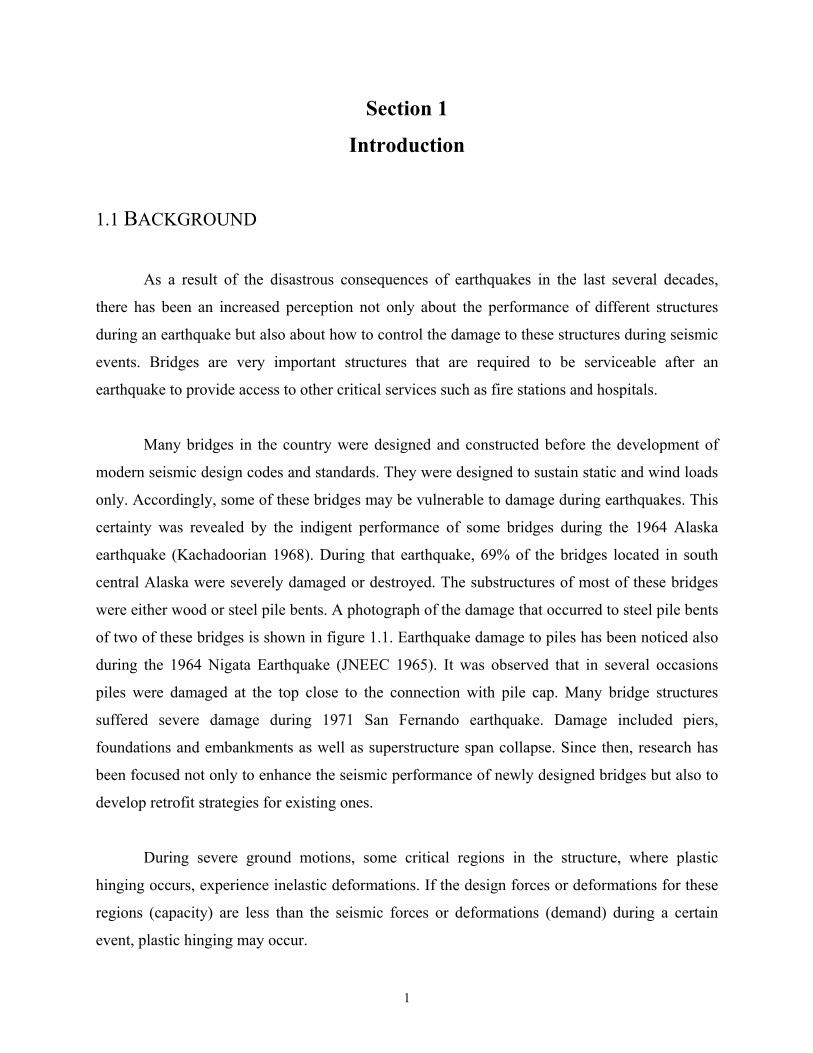
were either wood or steel pile bents. A photograph of the damage that occurred to steel pile bents
of two of these bridges is shown in figure 1.1. Earthquake damage to piles has been noticed also
during the 1964 Nigata Earthquake (JNEEC 1965). It was observed that in several occasions
piles were damaged at the top close to the connection with pile cap. Many bridge structures
suffered severe damage during 1971 San Fernando earthquake. Damage included piers,
foundations and embankments as well as superstructure span collapse. Since then, research has
been focused not only to enhance the seismic performance of newly designed bridges but also to
develop retrofit strategies for existing ones.
During severe ground motions, some critical regions in the structure, where plastic
hinging occurs, experience inelastic deformations. If the design forces or deformations for these
regions (capacity) are less than the seismic forces or deformations (demand) during a certain
event, plastic hinging may occur.

2
Figure 1.1 Damage occurred to two bridges during Alaska Earthquake 1964
(a) Damage Occurred to Steel Pile Bent on Scott Glacier Bridge
(b) Collapsed Bent and Deck of Copper River Bridge

3
Basic plasticity principles dictate that these plastic hinges mostly occur at the connections
between different elements within the structure. Figure 1.2 shows two locations in a bridge
structure where these plastic hinges can take place. The first one is a typical pile bent, where the
steel H-piles extend out of the soil directly to the pier cap. They are embedded approximately
300 mm into the reinforced concrete cap beam. In this form of construction, the plastic hinge is
anticipated to occur at the connection between the steel H-pile and the cap beam. In the second
form of construction, which is a pile supported foundation, the plastic hinge can take place at
the connection between the steel pile and the concrete pile cap. In both situations the local
performance of the connection has a major effect on the overall performance of the structure.
Therefore it is imperative to appraise the performance of these connections under cyclic loading
through a comprehensive experimental program and to develop methods for its retrofit assessed
by experiments to maintain its ductility during large cyclic drifts. The work presented herein is
an effort to contribute towards both goals.
1.2 OVERVIEW OF RELATED PREVIOUS WORK
Early research on single piles was directed mainly towards estimating their static load
carrying capacity. Other parameters such as geometrical and mechanical pile and soil properties,
type of piles, type of loading, and soil-pile-structure interaction were also investigated. However,
little effort has been devoted towards the evaluation of the ultimate lateral resistance of laterally
loaded piles or to assess the pile-to-pile cap connection performance under seismic or cyclic
lateral load. Broms (1964) presented methods for the calculation of the ultimate lateral resistance of
piles in cohesionless and cohesive soils. Satisfactory agreement was found between his work and
available test data at that time. The effect of cyclic loading on the lateral performances of piles was
investigated by Matlock et al (1978) and by Poulos (1982) who suggested that, for design purposes,
the effects of cyclic lateral loading can be taken into account by modification of the static analysis
of the pile. A common characteristic of all these studies, that they were localized on the behavior of
the pile and pile-soil interaction rather than the pile-to-pile cap connection. Shafer and Williams
(1947) investigated this connection. However, they tested the piles only under uniaxial compression

4
WALL PIER
PILE CAP
CAP BEAMCONNECTION UNDER CONSIDERATION
CONNECTION UNDER CONSIDERATION
STEEL PILESTEEL PILE BENT
Figure 1.2 Critical Locations in a Bridge Substructure where Plastic Hinges can take Place

5
Load. Therefore their findings are not relevant to the study of cyclic lateral loading for which the
behavior of the connection is dominated by the induced shear and bending moments.
A series of cyclic tests was conducted in New Zealand on prestressed concrete pile-to-cap
connections (Joen and Park 1990). The results showed that well detailed prestressed concrete piles
and pile-to-cap connections are capable of undergoing large post-elastic deformations without
significant loss in strength when subjected to severe seismic loading.
Another significant study concerning pile-to-cap connection has been done in British
Columbia, Canada (Steunenberg et al 1998) where a convenient design, for this connection, favored
by the Ministry of Transportation and Highways of British Columbia has been successfully tested.
This design consists of a steel anchorage plate embedded in the concrete pile cap. The plate is then
welded to the pile top after placement in the field. The design is different than what is followed in
the United States but it gives some insight for future design of this connection.
Chai and Hutchinson (1999) conducted an experimental program for bridge structures
supported on single extended reinforced concrete pile shafts, considering the pile-soil interaction in
their experiments. Four full scale 400mm diameter concrete piles with details representative of
current Caltrans design. Their study showed that the depth to the plastic hinge within the soil
decreases with an increase in the soil density and an increase in the above ground height.
A series of tests has been conducted at the University of Southern California (Xiao et al
1999) as a part of FHWA-MCEER Highway project, in order to investigate seismic behavior of
bridge steel pile-to-pile cap connections representative of construction in California. Five full-scale
H-shaped steel pile-to-cap connection subassemblies were tested during this experimental study.
Two of the full-scale subassembly specimens were subjected to vertical cyclic load simulating axial
forces in pile due to footing overturning during a seismic ground motion. Two other were loaded
with cyclic lateral force and constant vertical load. It was found that the pile to-cap connection can
sustain significant amount of moment.

6
Other relevant studies were devoted to strengthen structural steel connections embedded in
precast concrete by additional reinforcement or by providing holes in the steel web for the concrete
to enter (Rath, 1974). However, typical bridge pier piles do not employ these kinds of strength
enhancements and must rely entirely on the bond and adhesion developed between the steel and
concrete in the embedded region to resist the applied moments. The capacity of steel shapes used as
brackets (Mattock and Gaafar, 1982) and coupling beams (Harries et al., 1993) was also
investigated. The primary contribution of these articles has been in the use of the stress block
approach in the embedded region to develop expressions for the theoretical resistance of the
connections (Marcakis and Mitchell, 1980).
1.3 WHAT THEN IS PARTICULARLY NEW IN THIS STUDY?
This research is devoted to study the seismic performance of bridge pile-to-cap connections
that is representative of construction in the eastern and central United States. This problem was not
tackled previously. Simplified limit state theories are developed to predict the connection
performance under lateral loading. Based on these theories, design guidelines are suggested for
these connections. Such an approach has not been formally proposed previously for seismic design
of new bridge structures.
The conceptual elastic cap/elasto-plastic steel pile retrofit strategy proposed in this study is
a new approach that was not addressed before. Moreover, employing wire rope for confining the
plastic hinge zone within the concrete is a new and successful approach. The fatigue-life model
proposed in the present study, for retrofitted connections, which is a function of the pile section
dimensions is a new approach that can be used in future studies to predict the design fatigue-life
of these connections under cyclic loading .
1.4 SCOPE AND OBJECTIVES The behavior and capacity of cyclically loaded, H-pile-concrete pile cap connections has
received very little research. Retrofit strategies for these connections are still not assessed. Primarily

7
designed for vertical loading, these structures may be susceptible to damage from cyclic lateral
loading that would arise during seismic events.
The present work has three main objectives: (1) to explore and understand the performance
of the pile-to-cap connection under cyclic loading; (2) to develop simple procedures for the retrofit
of these connections and examine the validity of these procedures; (3) to provide the design
engineer with sufficiently accurate theoretical principles, yet simple enough to be used in practice
for predicting the behavior of these connections under different loading conditions.
In order to achieve these objectives, a theory is developed, based on bond and energy
considerations, capable of predicting the expected moment capacity of the pile-to-pile cap
connection. Theoretical predictions were assessed by experiments conducted on full-scale
specimens designed to focus on the pile-to-cap connection in both strong and weak axis directions.
Pile specimens were tested to failure under vertical loads using quasi-static reversed lateral cyclic
loading to assess the effect of axial load-moment interaction on both interior (vertical) and exterior
(battered) piles. In view of the performance of these specimens, a retrofit strategy was developed
and applied to the specimens that performed faulty during the experiments. The retrofitted
specimens were tested again to assess the developed retrofit procedure. On the basis of the
experimental study, a seismic damage assessment criterion is proposed for bridge structures
supported by piled foundations.
1.5 ORGANIZATION The organization of this report: following this introductory section, the remaining sections
are organized as follows. Section 2 presents an analysis of the potential plastic mechanism for pile
bents and pile foundations, taking into account the effect of pile-soil interaction. Theories are
developed for predicting the strength of the pile-to-pile cap connections based on elastic and
inelastic concrete assumptions. The connection efficiency was determined in view of the developed
theories. Section 3 describes the steps involved in the construction of the test specimens followed by
the experimental setup that was developed to undertake full-scale tests on the pile-to-cap
connections. This section also outlines the different methods that can be employed to accommodate

8
the axial load variation for this kind of experiments. Section 4 presents results for the seven
experiments performed to evaluate the seismic vulnerability of existing pile-to-cap connections.
Section 5 presents the steps involved in the retrofit strategy proposed in this study and outlines the
results of the experiments on the retrofitted specimens that performed poorly in the first series of
experiments. Section 6 validates the theories developed in Sections 2 and 3 for predicting the lateral
force displacement relationship and ductility ratio by comparing the experimental results with the
results obtained utilizing these theories for different pile-to-cap connections. A fatigue theory is then
developed in this section for the low cycle fatigue behavior of the specimens that failed in such
failure mode. Section 7 presents a summary of the work reported herein, conclusions drawn from
the theoretical and experimental aspects of this work, and recommendations for future research are
given.

9
SECTION 2
THEORETICAL CAPACITY OF PILE-TO-CAP
CONNECTIONS
2.1 INTRODUCTION
In this section, theories are developed to predict the capacity of pile-to-cap connections.
The problem is treated first from a global point of view, where potential plastic mechanisms for
pile bents and pile foundations are outlined. Admissible plastic mechanisms are postulated that
include the effect of pile-soil interaction. This is followed by development of simplified
theoretical concepts that look closely at the connection itself and predict its local behavior under
different lateral and axial load patterns. The theory is then utilized to provide design guidelines
and retrofit strategies for these connections. Finally, a comparison is made between the
simplified limit theories with a rigorous finite element analysis.
2.2 GLOBAL PLASTIC MECHANISMS FOR PILES AND PILE BENTS
Figure 2.1 presents a steel pile bent and a postulated collapse mechanism for lateral
(earthquake) loading. It is assumed that plastic hinges will take place somewhere within the
embedded length of the pile. Determination of this location will be discussed in detail in the next
subsection. If it is assumed here that any potential settlement for the pile group due to the
working vertical loads has already taken place before reaching the state of this mechanism, then
the vertical reaction of the piles do not perform any work. The external work done (EWD) by the
lateral loading for a virtual (horizontal) displacement ∆ (drift) can be expressed as:
HWCWCFEWD cC θ=∆=∆= (2.1)

10
Figure 2.1 Potential Plastic Mechanism for Pile Bents
(b) Potential Collapse Mechanism
(a) Typical Geometry of Steel Pile Bent
ρMp
−γF
Mp
F=Cc W
MpMp Mp
ρMp
∆
ρMp
θ
ρMp
F=Cc W
W=4P
γF
H

11
where F = the total lateral force on pile bent; W= the seismic weight of the superstructure; CC =
seismic base shear capacity coefficient; θ =rotation angle, and H = equivalent height of the pile
between plastic hinges.
The internal work done (IWD) can be quantified as:
)1(nMIWD P +ρθ=
in which n = number of piles in the bent; PM = plastic moment capacity of the pile section; and
ρ = pile connection efficiency, expressed as the ratio of the nominal moment capacity of the
concrete cap beam at the hinge location to the plastic moment capacity of the pile steel section.
Note that for a hinge condition ρ = 0 and for a fully fixed condition ρ ≥ 1.
Equating the external work done (2.1) with the internal work done (2.2), an expression
for the base shear capacity of the bent can be evaluated as:
t
Pc WH
)1(nMC
+ρ=
If it is assumed that the superstructure seismic weight is shared equally between the
number of piles such that each of them carries an axial load eP , the superstructure seismic
weight can be expressed as:
et PnW =
Substituting equation (2.4) in (2.3) gives:
e
pc PH
)1(MC
+ρ=
(2.2)
(2.4)
(2.3)
(2.5)

12
It should also be noted that, due to the additional axial thrust at piles, their plastic
moment capacity is reduced. The following well-known moment-axial load interaction
expressions for PM according to ASCE 1971 can be utilized:
Strong axis bending:
For YP15.0P0 ≤≤
PPC MM =
For YY PPP15.0 ≤≤
PY
PC M)PP1(18.1M −=
Weak axis bending: Neglecting the contribution of the web to the plastic capacity it can be
shown that for weak axis bending:
P
2
YPC M
PP1M
−=
Where PCM = plastic moment capacity of piles including axial load effects.
2.3 PILE-SOIL INTERACTION REPRESENTATION
From equation (2.5) it is evident that the base shear capacity of the pile bent is dependent
on the length between the hinges (H). The lower hinges in the bent are beneath the ground
surface by some depth. In this subsection, it is the primary objective of studying the pile-soil
interaction under ultimate load to estimate the distance between the two plastic hinges. The
effective length is taken as the clear distance from the inflection point at the pile to the point of
the connection between the steel pile and the concrete cap beam. For the purpose of investigating
the soil-structure interaction, a single interior pile is examined, and the connection efficiency will
be set to unity for simplicity. Two cases are considered: Case (1) where a pile is totally
embedded in soil (pile foundation); and Case (2) where a pile extends above the soil (pile bent).
(2.6)
(2.7)
(2.8)

13
2.3.1Cohesionless soil
The following assumptions are made using the well-known approach adopted by Broms (1964b):
1. The active earth pressure acting on the back of the pile is neglected.
2. The distribution of passive pressure along the front of the pile is equal to three times the
Rankine passive pressure.
3. The shape of the pile section has no influence on the distribution of the ultimate soil
pressure or the ultimate lateral resistance.
4. The full lateral resistance is mobilized at the movement considered.
5. The piles are relatively long and hence, the ultimate lateral resistance will be governed by
the plastic moment capacity of the pile section.
Brom's simplified assumption of ultimate soil resistance being equal to three times the
Rankine passive pressure is based on limited empirical evidence from comparisons between
predicted and observed ultimate loads. These comparisons suggest that the assumed factors of 3
may in some cases be conservative, as the average ratio of predicted to measured ultimate loads
is about two thirds.
Case (1): Pile Foundation:
According to the aforementioned assumptions one is able to apply the theory of virtual
work to the pile mechanism with soil reactions figure 2.2a and b. It is assumed, for simplicity,
that the pile is embedded in a uniform homogeneous layer of soil. The external work done on one
pile is:
θ= FHEWD
Where F = the lateral load acting on pile, H = the distance between the two plastic hinges. The
internal work done on the pile and soil is:
θγ+θγ+θ= P3
PP02
Pp dHK5.0dHHK23M2IWD
(2.9)
(2.10)

14
Figu
re 2
.2 S
oil S
truc
ture
-Int
erac
tion
Rep
rese
ntat
ion
in P
last
ic
Mec
hani
sm o
f Pile
Fou
ndat
ions

15
in which 0H = The embedded depth of the cap beam; Pd = the depth of the steel pile section; θ =
the plastic rotation of the pile; γ= the unit weight of the soil considered; and PK = Rankine
coefficient of passive earth pressure evaluated as:
( )( )φ−
φ+=sin1sin1K P
where φ= the angle of internal friction for the cohesionless soil.
Equating the external work done equation (2.9) to the internal work done equation (2.10), a value
for the shear carried by one pile can be obtained as follows:
2PP0PP
P HdK5.0HHdK5.1HM2
V γ+γ+=
According to the upper bound theorem of collapse, the minimum value of V is required to obtain
the correct mechanism. Minimizing equation (2.12) with respect to H as follows:
HdKHdK5.1HM2
0dHdV
pp0pp2p γ+γ+−==
Upon rearrangement of equation (2.13) this gives:
3
pp2
0ppp HdKHHdK5.1M2 γ+γ=
Dividing equation (2.14) by 4pd and rearranging gives the following dimensionless expression:
3
p
2
pp
0
p4p
p
dH
dH
dH
5.1Kd
M2
+
=
γ
Further simplification of equation (2.15) leads to the following expression for the normalized
distance between plastic hinges pd/H :
(2.11)
(2.13)
(2.15)
(2.12)
(2.14)

16
31
p
p
0
4pp
p
p
dH
dH5.1
1
dKM2
dH
+
γ=
Now defining the shear span aspect ratio as p
p
p VdM
dL = one obtains:
22pp0
2pp
pp
p
p
p
p HdK5.0HHdK5.1H
dM2
MVdM
dL
γ+γ+==
Further simplification of equation (2.17) gives:
+
γ+
=
p
p
03
pp
4pp
p
p
dH
dH
31dH
M2dk
2
dH
dL
Equation (2.18) can be used in conjunction with equation (2.12) to obtain the effective
length L. This is illustrated through the following numerical example.
Example Consider a pile-to-cap connection with an embedded depth for the cap equals 2.5 m. It
is assumed that the pile is driven in loose silty sand (unit weight = 15.5 kN/ 3m , angle of internal
friction = 020 ). The HP (10x42), a section extensively used in pile foundation construction, is
(2.17)
(2.18)
(2.16)

17
considered. Equation (2.12) was then employed to evaluate the shear carried by the pile V for a
wide range of H values and the relationship is plotted in figure 2.3, where H was normalized by
dividing by pd . A minimum value of V = 289.3 kN is obtained from this relationship with a
corresponding value of pd/H = 12. The value of pd/H was then substituted in equation (2.18)
to obtain the normalized effective length pd/L . For the soil properties and pile steel section
assigned, the effective length was determined as 864mm.
The above procedure was employed to determine the normalized distance between the
plastic hinges pd/H corresponding to the minimum value of V. Two HP steel sections, HP
10x42, and HP 12x63, usually used in practice were utilized for this study. Some cases
representing different probable pile-soil conditions were considered for each section. The charts
shown in figure 2.4 illustrate these cases. The distribution of the 72 values of pd/H obtained
from this analysis is portrayed in figure 2.5. As can be seen the distribution is approximately
lognormal with median and coefficient of variation of 13 and 0.32, respectively. The median
value was implemented in equation (2.16) and a simplified expression for the normalized
distance between plastic hinges can be obtained as:
31
p
0
4pp
p
pd
H12.01
dKM2
dH
+
γ=
If equation (2.19) is substituted in equation (2.18), a general equation for pd/L can be obtained
as:
(2.19)

18
Figure 2.3 Evaluation of the Minimum Value of the Shear Carried by Pile and the Corresponding Value of the Distance between Plastic Hinges
0
500
1000
1500
2000
2500
0 10 20 30 40
H/dp
V (k
N)
HP 10X 42H0 = 2.5 mγ = 15.5 kN/m3
φ = 20

19
γ =
15kN
/m3
φ =
20φ
= 30
φ =
40
H =
14
mH
= 1
m4
H =
1m
4
12 C
ases
12 C
ases4
φ =
40
γ =
18 k
N/m
φ =
30
H =
1m
4 =
1H
φ =
50
m =
1H
4m
3
12 C
ases4
φ =
20
γ =
10 k
N/m
φ =
10
H =
1m
4 =
1H
φ =
30
m =
1H
4m
3
Figu
re 2
.4 C
hart
s illu
stra
ting
the
Num
ber
of C
ases
use
d to
det
erm
ine
an A
vera
ge V
alue
for
H/d
p

20
Figure 2.5 Lognormal Distribution of the Distance between Plastic Hinges for Different Pile-Soil Conditions
0
0.25
0.5
0.75
1
0 5 10 15 20 25H/dp
CU
MU
LA
TIV
E P
RO
BA
BIL
ITY
MEDIAN = 13COV = 0.32

21
γ
+
+
++
+
γ=
−
31
4pp
p
p
0
p
0
32
p
03
1
p
0
31
4pp
p
p
dKM2
dH12.01
dH
31
dH12.01d
H12.012
dKM2
31
dL
31
Further simplification of equation (2.20) leads to:
31
4pp
pburied
p dKM2
3K
dL
γ=
where for non-buried foundations 1K buried = , and for buried foundations
γ
++
+
+
=3
1
4pP
p
p
0
p
0
p
0
32
p
0
buried
dKM2
dH12.01
dH31d
H08.01
dH12.01
K
The effect of the cap embedment depth on the effective pile length is illustrated for two
HP sections in figure (2.6). The exact values for pd/L are plotted as well as the values obtained
using the simplified equation (2.21). It is shown that the pile effective length decreases with
increasing the cap embedment depth. Also, there is a satisfactory agreement between the exact
solution and equation (2.21)
Using the above procedure, the relationship of pd
L versus the internal angle of friction
for various types of soils is plotted in figure (2.8a). These values represent shales, silty sand, and
sandy gravel. The geometrical as well as the material properties of the 10X42 HP steel piles
(2.22)
(2.20)
(2.21)

22
Figure 2.6 Relationship between the Pile Cap Embedment Depth and the Effective Length
0
1
2
3
4
5
6
0 5 10 15 20
NORMALIZED EMBEDMENT DEPTH OF PILE CAP (H0/dp)
NO
RM
ALI
ZED
EFF
ECTI
VE
LEN
GTH
(L/d
p)
HP 10X42 Exact Method
HP 10X42 Approx. Eq.
HP 12X63 Exact Method
HP 12X63 Approx. Eq.

23
was used in the development of these curves. A value of 2.5 m was assumed for 0H . Note from
the figure that value of pd
L for pile foundations in cohesionless soils can range from 2 pd to 5 pd .
It can also be observed, that the effective length of piles increases with decreasing the internal
angle of friction of soil.
Case (2): Pile bent:
The pile bent is a special case of the general pile foundation structure. According to
figure 2.7, it will be assumed that the point of inflection lies in the middle distance between the
two plastic hinges i.e. L=0.5H. Therefore, the goal is to determine the distance Z, defined as the
depth within the soil to the plastic hinge. Applying the theory of virtual work for the mechanism
shown in figure (2.7a), and (2.7b), the internal work done on the pile and soil is:
θγ+θ= 3PPp ZdK
21M2IWD
and the external work done taken same as equation (2.9) with H = h+Z:
θ+= )Zh(FEWD
Equating the external work done equation (2.9) to the internal work done equation (2.24)
therefore:
( )ZhZdK5.0M2
F3
ppp
+γ+
=
The minimum value of P is required for an upper bound collapse. Therefore, minimize P with
respect to Z, therefore:
( )( )( )
( )( )2
2pp
2
3pp
2pp
2p
Zh
h5.1ZZdK
Zh
ZdK5.0ZhZdK5.1
Zh
M2
+
+γ=
+
γ−+γ=
+
(2.23)
(2.24)
(2.25)
(2.26)

24
Figu
re 2
.7
Soil
Stru
ctur
e-In
tera
ctio
n R
epre
sent
atio
n in
Pla
stic
M
echa
nism
of P
ile B
ents

25
Further simplification of equation (2.26) gives:
0dK
M2hZ5.1Z
pp
p23 =γ
−+
Therefore the normalized depth to maximum moment can be evaluated as:
31
2
pp4pp
p
p dZ
dh5.1
dKM2
dZ
−
γ=
Equation (2.28) can be solved by fixed point iteration.
2.3.2 Cohesive soil:
According to Broms(1964a), it has been assumed that the lateral soil reaction is equal to
zero to a depth of 1.5 pile depth and equal to 9.0 PUdC below this depth, where UC is defined as
the cohesion of the soil considered, determined from undrained triaxial, direct shear or vane
tests. The piles are relatively long and hence, the yielding of the pile section rather than failure of
the surrounding soil governs the failure.
Case (1) Pile foundation:
Consider the plastic mechanism of the pile foundation shown with soil reactions
in figure (2.2a) and (2.2c) and applying the theory of virtual work for this mechanism, therefore
the external work done on the pile is taken same as equation (2.9). The internal work done on the
pile and soil can be expressed as:
θ+θ= 2PUp HdC
29M2IWD
Equating the external work done (2.9) to the internal work done (2.29), the shear carried by one
pile is determined as:
(2.27)
(2.28)
(2.29)

26
H2HdC9M4
V2
PUP +=
According to the upper bound theorem of collapse, the minimum value of V is required to obtain
the correct mechanism. Consequently, minimizing equation (2.30) with respect to H, therefore an
expression for the normalized distance between the plastic hinges can be obtained as:
21
3pU
p
p dCM
32
dH
=
Defining the shear span as V
ML p= one obtains:
+
==HdC
29
HM2
MV
ML
pUp
pp
Further simplification in terms of pile diameter pd therefore:
21
3pU
p
p dCM
61
dL
=
(2.30)
(2.31)
(2.33)
(2.32)

27
(a) Cohesionless Soil
0
1
2
3
4
5
6
7
0 10 20 30 40 50 60ANGLE OF INTERNAL FRICTION OF SOIL
NO
RM
ALI
ZED
EFF
ECTI
VE L
ENG
TH O
FPI
LE (L
/dp)
SHALES
SILTY SAND
GRAVELLY SAND
0
2
4
6
0 20 40 60 80
SOIL COHESION (kN/m2)
NORM
ALIZ
ED E
FFEC
TIVE
LEN
GTH
OF
PILE
(L/d
p)
(b) Cohesive soils
Figure 2.8 Effect of Soil Parameters on the Effective Length of Pile specimens

28
The relationship between the cohesion of soil and the normalized effective length of the pile was
evaluated using equation (2.33). The relationship is plotted in figure 2.8b. It can be concluded
from that figure that the normalized effective length of the pile specimen (L/ pd ) can vary from a
value of 2 pd to 6 pd depending on the soil parameters used.
Case (2) Pile Bent:
The principle of virtual work for the plastic mechanism shown in figure (2.7a) with soil
reactions in (2.7c) is adopted:
θ++= )efh(PEWD
in which, h= the clear distance from the plastic hinge at pile-to-cap connection to the soil surface,
e= soil depth where the lateral soil reaction equals zero, and f = the embedded depth to the
second plastic hinge excluding e. The internal work done on the pile and soil can be expressed
as:
θ+θ= 2PUp fdC
29M2IWD
Equating the external work done equation (2.34) to the internal work done equation (2.35) gives:
)efh(fdC5.4M2
P2
PUP
+++
=
Minimizing this expression with respect to f gives:
( ) 0M2ehfdC9fdC5.4 ppU2
pU =−++
Solving equation (2.37) for f and adding e, an expression for Z can be obtained as:
( )( )
e1ehdC
M44.01ehZ 2
PU
P +
−
+++=
(2.37)
(2.38)
(2.34)
(2.36)
(2.35)

29
Results of the analyses of pile bents in cohesionless and cohesive soils suggests that a typical
depth to maximum moment lies in the range 3 Pd to 9 Pd , depending on the soil properties used
in the calculation. As an approximation a value of 5 Pd is used in the present study.
2.4 PILE-TO-CAP CONNECTION EFFICIENCY-ELASTIC BEHAVIOR FOR
CAPACITY DESIGN
An objective of the present study is to determine the strength and ductility of pile-to-cap
connection under highly plastic drifts, and hence provide retrofit methodologies for improving
the seismic performance of this connection. The plastic crushing moment capacity of the
concrete cap beam as well as the plastic moment capacity of the steel pile control the
performance of the connection under high drifts. As steel is more ductile than concrete, failure of
the connection under severe seismic drifts is expected to occur when the concrete stress reaches
its crushing capacity, while the steel pile section is still capable to absorb more energy.
Consequently, connection efficiency is defined as:
P
j
MM
=ρ
where jM = moment capacity of the concrete-pile connection (joint); and pyp ZfM = = nominal
moment capacity of the pile. If ρ > 1 then plastification in the pile is expected, whereas if ρ < 1
damage to the connection is expected.
In what follows, using basic principles, it will be focused on developing two theories for
the evaluation of the connection efficiency. The theories are developed for strong axis bending
direction and the same approach can be used for the weak axis direction.
(2.39)
30
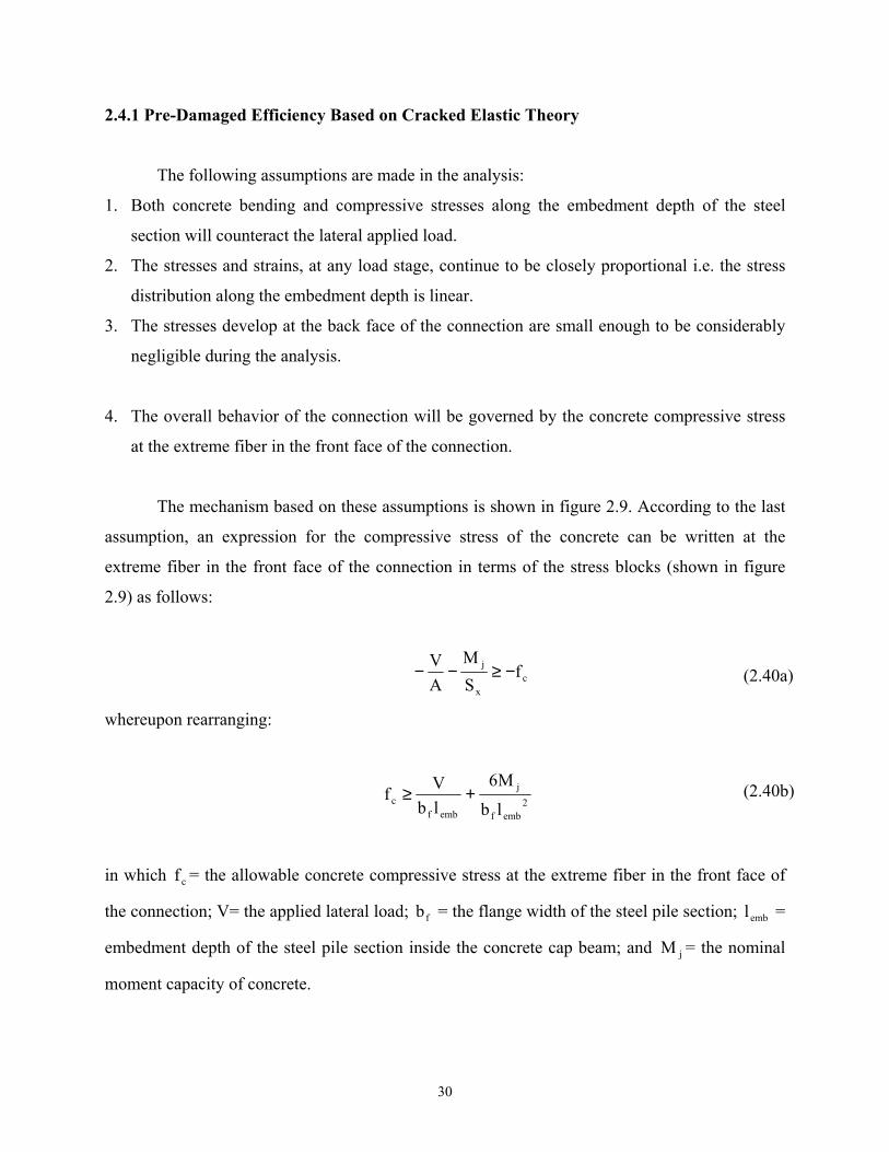
2.4.1 Pre-Damaged Efficiency Based on Cracked Elastic Theory
The following assumptions are made in the analysis:
1. Both concrete bending and compressive stresses along the embedment depth of the steel
section will counteract the lateral applied load.
2. The stresses and strains, at any load stage, continue to be closely proportional i.e. the stress
distribution along the embedment depth is linear.
3. The stresses develop at the back face of the connection are small enough to be considerably
negligible during the analysis.
4. The overall behavior of the connection will be governed by the concrete compressive stress
at the extreme fiber in the front face of the connection.
The mechanism based on these assumptions is shown in figure 2.9. According to the last
assumption, an expression for the compressive stress of the concrete can be written at the
extreme fiber in the front face of the connection in terms of the stress blocks (shown in figure
2.9) as follows:
cx
j fSM
AV −≥−−
whereupon rearranging:
2embf
j
embfc lb
M6lbVf +≥
in which cf = the allowable concrete compressive stress at the extreme fiber in the front face of
the connection; V= the applied lateral load; fb = the flange width of the steel pile section; embl =
embedment depth of the steel pile section inside the concrete cap beam; and jM = the nominal
moment capacity of concrete.
(2.40b)
(2.40a)

31
The applied lateral load can be expressed as:
*j
LM
V =
where *L = the distance from the point of application of the lateral load to the neutral axis of the
joint. Substituting equation (2.41) in (2.40) gives:
+≥ 2
embfembf*jc lb
6lbL
1Mf
Solving for the joint moment gives:
+
≤
*emb
emb2
fcj
Ll
6
lbfM
Introducing the connection efficiency ρ as defined in equation (2.39), therefore:
)L
l6(Zf
lbf
*emb
Py
2embfc
+=ρ
Where, yf = the yield stress of the steel pile section, pZ = the plastic modulus of the steel pile
section approximately can be expressed as:
pffp dbtZ ≈
in which ft = the pile steel section flange thickness; and Pd = the pile steel section depth.
(2.43)
(2.41)
(2.42)
(2.44)
(2.45)

32
Figure 2.9 Stress Distribution for Cracked Elastic Theory
L*L
lemb
V
-V/A - M/Sx -fc

33
Therefore the connection efficiency can be quantified as:
+
=ρ
*emb
2
P
emb
f
P
y
c
Ll
6
dl
td
ff
*emb L/l can range from 0.1, for the case of pile bents, to 0.5 for pile foundations. Taking an
average value of 0.3 and substitute in equation (2.46) an expression for the elastic (pre-crushing)
efficiency is obtained:
2
p
emb
f
p
y
c
dl
td
ff
16.0
=ρ
By inverting equation (2.47) one can obtain a design expression for determining the required
embedment length
ρ=
p
f
c
y
p
emb
dt
ff
16.0dl
At section overstrength ysu ff ρ= with 6.1=ρ . Adopting a value of 'cc f85.0f = and substituting
into the above equation gives:
=
p
f'c
y
p
emb
dt
ff
4.3dl
(2.46)
(2.47)
(2.48)
(2.49)

34
2.4.2 Design Requirements with the Cracked Elastic Theory
It is of great interest for practicing engineers to use simple and transparent approaches to
achieve their design objectives. This concept can be applicable for the future designs and design
code provisions for pile-to cap connections under lateral loads, using the theories presented in
this study. The cracked elastic theory, a conservative theory for design, can be used as an upper
bound. Developed for high strain levels, the post ultimate plastic theory, described in the next
subsection, can be used as a lower bound for estimating the embedment depth for these
connections due to horizontal loads.
The cracked elastic efficiency is governed by the compressive stress at the extreme fiber
of the front face of the connection. Therefore, design requires determination of the stress level at
the concrete surface, after selecting the appropriate embedment depth. Figure 2.10 presents
relationships between the normalized embedment depth and the pre-damaged efficiency, for an
allowable stress of 'cc f85.0f = . Using this stress ensures that premature concrete crushing will
not occur. If an efficiency of ρ = 1.6 is adopted for design, (this value allows for connection
overstrength) then the required embedment depth can be found.
2.5 A THEORETICAL VALIDATION OF THE CRACKED ELASTIC DESIGN
ASSUMPTIONS
2.5.1 Finite Element Modeling of Pile-to-Cap Connection
During the last four decades the finite element method has been developed and improved
to become applicable for most of the civil and structural mechanics problems, and also extended
to cover different areas such as mechanical and aerospace engineering. The evolution in the last
two decades of computer hardware capabilities conferred this method more popularity among the
engineering community. Basically, the finite element analysis of a continuum consists of three
steps:

35
Figure 2.10 Pre-Damaged Efficiency for Different Compressive Strength
0
1
2
3
0 1 2 3 4lemb / dp
PRE-
DAM
GED
EFF
ICIE
NC
Y
f'c= 20 MPa
f'c= 30 MPa
f'c= 40 MPa
concrete& steel damage
mostly concrete damage
ideal design range
mostly steel damage

36
Structural idealization, whereby the continuum is idealized as an assemblage of a number of
discrete elements connected at the nodes only
(i) Specifying the relation between the internal displacements of each element and its nodal
displacements. This is done by using a displacement function to specify the pattern in
which the element is to deform. On the basis of this displacement function, one can
derive the element stiffness matrix which relates the element nodal forces to the element
nodal displacements.
(ii) The structural analysis of the idealized assemblage of discrete elements. This analysis is
carried out by the standard matrix stiffness procedure.
Although, classified as an approximate method for structural analysis, the finite element
method proved its efficiency in idealizing different physical problems with satisfactory
convergence. In the following pages, the cracked elastic theory developed earlier in this section
will be validated by comparing its results to the finite element method.
2.5.2 Model Description
Two models were developed for comparison with the cracked elastic theory developed
herein. The first model, denoted here as model 1, represents a short exterior pile with a 300 mm
embedment depth in a concrete pile cap. The dimensions of the pile and pile cap are same as
those of pile specimen P1 which will be described in detail in section 4. Therefore the length,
width and height of the pile cap were taken as 1450 mm, 1000 mm, and 900 mm respectively.
Fixed boundary conditions were assigned to all the nodes at the interior edge surface to be
consistent with the experimental setup, where that edge was anchored to the laboratory strong
floor by means of an anchoring beam. The lever arm for that model was taken as 785mm from
the concrete surface to conform to the experiment. The direction of the lateral load for this model
was set so that the bending be along its strong axis.
The second model denoted as model 2 represents a long interior pile loaded along its
weak axis bending. Geometry and boundary conditions of that model are consistent with pile
specimen W1 (details of this test specimen is given in section 4). The length of the concrete

37
beam (2400mm) was taken equal to the distance where the concrete specimen was anchored to
the laboratory strong floor. Fixed boundary conditions were assigned to all the nodes at the edge
surfaces in both ends where it was anchored to the floor. The width and the depth were taken as
700mm and 600 mm respectively. The lever arm for this model was taken as 2616mm. The
geometrical properties of the steel section were taken as HP10X42, for the two models.
2.5.3 Types of Elements
Finite element meshes for the two models were generated using the FE analysis package
PATRAN version 7.6 (PDA Engineering), and the finite element analyses were performed using
the ABAQUS code version 5.7 (Hibbitt, Karlsson, and Sorensen, Inc.). An 8-node linear brick
element of the type C3D8 was used to limit the computational time to a reasonable extent.
82.5X82.5X80 mm brick elements were used for the concrete cap beam in model 1. The same
dimensions, except for the thickness were assigned to the steel section. 18270 nodes and 13260
elements were used for model one. In the region surrounding the steel section and extending 623
mm from both sides, 45X45X60 mm brick elements were used to model the concrete cap beam
in model 2. The length of the element, however, was increased to 144.25 mm for the regions
beyond 623mm from both sides. 7856 nodes and 5989 elements were used for model two.
Typical FE meshes of model one, and two are shown in figures 2.11, and 2.12.
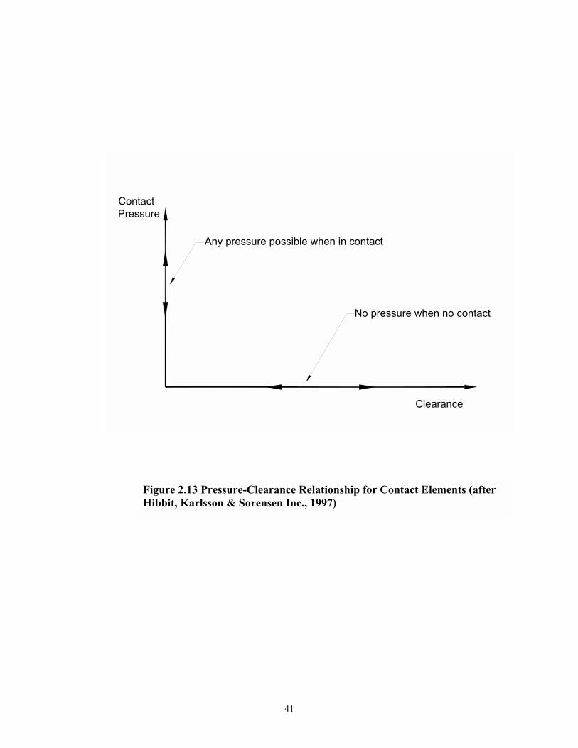
Contact gap elements of the type GAPUNI were used to model the steel-concrete
interaction during loading. These contact elements were necessary to transfer the lateral forces
properly from the steel pile to the concrete beam during loading, and hence leading to the
appropriate distribution of stresses along the embedment depth. Each gap element allows for
contact between two nodes. One node is located on the steel section and the other one is located
in the same location on the concrete beam. Therefore, each gap element was defined by
specifying the two nodes forming the gap and providing geometric data defining the initial state
of the gap. In the present study the initial state of the gap was set to zero, that is the surfaces are
initially bonded. The contact pressure-clearance relationship used in the present study is shown
in figure 2.13. When the two nodes of one element are in contact, any contact pressure can be
transmitted between them. The nodes separate if the contact pressure reduces to zero. Separated

38
Figure 2.11 FEM Model 1 Short Exterior Pile

39
Figure 2.12 FEM Model 2 Long Interior Pile (Weak Axis)

40
nodes come into contact when the clearance between them reduces to zero. A friction property is
associated with each gap element. This friction property controls the slipping of the surfaces, in
contact, relative to each other. In the present study the basic Coulomb friction model was used to
represent the friction between the interacting surfaces. On the basis of this model, the two
contacting nodes can carry shear stresses up to a certain magnitude across their interface before
they start sliding relative to one another. The Coulomb friction model defines this critical shear
stress at which sliding of the surfaces starts as fraction of the contact pressure between the
surfaces. The user specifies this fraction known as the coefficient of friction. Several values for
the coefficient of friction were tried in the present study. It was observed that increasing the
coefficient of friction results in a slight decrease of the compressive stresses of concrete along
the embedment depth. Consequently, a value of 0.6 was used in this study for the coefficient of
friction. A total number of 180 gap elements was used to represent the contact between the steel
section and the concrete beam for model one. This number was 330, and 234 for model two and
three respectively.
2.5.4 Material Constitutive Models
2.5.4.1 Steel Pile Model
The material properties used for the steel material in the elastic phase are as follows: modulus of
elasticity = 200000 MPa, Poisson ratio = 0.28 and yield stress = 315 MPa. Those values are
equal to those obtained from the coupon test of the HP 10X42 steel section. The results of this
test are discussed in detail in section 3. The plastic behavior of the steel material was modeled
using the classical metal plasticity mode in ABAQUS. This model uses Mises yield surface with
associated plastic flow and isotropic hardening.
2.5.4.2 Concrete Beam Model
The material properties used for concrete are as follows: compressive strength after 28 days = 40
MPa, plastic strain at failure = 0.002, and Poisson ratio = 0.18. The Modulus of elasticity of
41
Figure 2.13 Pressure-Clearance Relationship for Contact Elements (after Hibbit, Karlsson & Sorensen Inc., 1997)
Any pressure possible when in contact
No pressure when no contact
Clearance
ContactPressure

42
concrete was determined according to the following equation (ACI-318):
MPaf4700E 'cc =
in which cE = Modulus of elasticity of concrete, and 'cf = concrete compressive strength. For
the present study, a concrete strength of 'cf = 40 MPa was assumed.
The compressive and cracking response of concrete that are incorporated in the
ABAQUS concrete model are illustrated in figures 2.14, and 2.15. When concrete is loaded in
compression, it initially exhibits elastic response. As the stress is increased, some irrecoverable
inelastic straining occurs and the response of the material softens. The failure domain in
compression is completed when an ultimate stress is reached whose analytical formulation is
written in terms of the equivalent pressure stress and the Von Mises equivalent deviatoric stress.
Cracking is assumed to occur when the stress reaches a failure surface that is called the crack
detection surface. The model is characterized by tension stiffening post-failure behavior to
represent the post-cracking softening of concrete.
For the present study, the concrete cap beams are characterized by little reinforcement.
Therefore, the tension stiffening was defined in terms of a maximum displacement at which a
linear loss of strength after cracking gives zero stress. The determination of this maximum
displacement was based on an energy approach in which the concrete's brittle behavior is
characterized by a stress-displacement response rather than a stress-strain response. One can
refer to the ABAQUS 5.7 theory manual for more details about this formulation. For the present
study, this maximum displacement was taken as 0.5 mm. This value is well above the default
value used in ABAQUS (0.1mm). However, it was adequate to avoid early divergence problems
of the nonlinear algorithm that may prevent the progress of the solution at early stages.
Defined as small tensile strength material, concrete has a residual capability of transmitting
shear forces in the presence of cracking. This is the effect of a rough crack configuration due to
(2.50)

43
σ1
σ2
biaxial compression
biaxial tensionuniaxial tension
uniaxial compression
crack detection surface
compression surface
Start of inelastic behavior
Cracking failureSoftening
Failure point in compression(peak stress)
Strain
Stress
Figure 2.14 Uniaxial Behavior of plain Concrete (after Hibbit, Karlsson & Sorensen Inc., 1997)
Figure 2.15 Yield and Failure Surfaces in Plane Stress (after Hibbit, Karlsson & Sorensen Inc., 1997)

44
aggregate interlock. From a computational point of view, this phenomenon is taken into account
in ABAQUS by means of the so-called shear retention option, which specify the reduction in the
shear modulus as a function of the opening strain across the crack. In the present study full shear
retention was assumed, as the overall response is not strongly dependent on the amount of shear
retention.
Two more values needed to be specified for the concrete model to define the shape of the
failure surface. These values are the ratio of the ultimate biaxial compressive stress to the
uniaxial compressive ultimate stress, and the ratio of the uniaxial tensile stress to the uniaxial
compressive stress at failure. These values were taken as 1.16 and 0.1 respectively.
2.5.5 Nonlinear Analysis Algorithm
Although from first appearances the models look simple, but they are considered highly
nonlinear problems. Nonlinearities in such models arise from the nonlinear material concrete in
addition to the boundary nonlinearities i.e. contact and friction. In fact, accompanying both the
friction and the concrete material model usually causes some divergence problems specially
when cracks start to take place. In order to avoid premature reductions of the time increments,
the number of equilibrium iterations for a residual check and the number of equilibrium iteration
for a logarithmic rate of convergence check were set to 50 and 70 respectively. It is
recommended for severely discontinuous problems to increase these two parameters on the
CONTROLS option. The line search algorithm was used to avoid divergence of the solution in
the early iterations. The analysis was conducted in load control. For such problems, it is
preferable to use a direct user-specified fixed time incrementation with very small time
increments rather than using the automatic time incrementation by ABAQUS.
2.5.6 Comparison of Results with the Cracked Elastic Theory
Comparisons between the FEM models with the cracked elastic theory are in terms of
the compressive stress at the concrete surface and the distribution of stresses along the steel-
concrete interface. Equation (2.43) can be rearranged and written in the following form:

45
2embf
*emb
0
c lbL
l6M
f
+
≥
in which 0M = the applied moment by the lateral load. Equation (2.51) is compared to the two
FEM models in terms of the compressive stresses at the concrete surface, and the distribution of
stresses along the embedment depth.
Model 1 was analyzed under a 120 kN lateral load. Taking into consideration that the
lever arm of this specimen was taken as 785mm. Therefore the applied moment can be quantified
as 94.2 kNm. Substituting this value in equation (2.51), therefore the compressive stress at the
concrete beam surface can be obtained as 26 MPa. Contour plots, from the ABAQUS program,
of the compressive stresses for this model are shown in figure 2.16. One can observe that the
distribution of stresses along the flange width is not uniform. Consequently, the comparison is
made in terms of the average stresses along the flange width. The distribution of the compressive
stresses along the flange width ranged from 6 MPa at the flange edge to 36 MPa at the center.
An average value of 20 MPa can be taken for the compressive stress at the concrete surface. This
value agrees reasonably with the theoretical formula proposed in this study.
Figure 2.17 illustrates the distribution of stresses for model 2 under 10 kN lateral loading.
As mentioned earlier the lever arm of this case was taken as 2616 mm, which results in 26.2
kNm applied moment at the connection. Again the distribution of stresses along the steel pile
depth is not uniform. Note that a major part of the section depth had a 9 MPa stress. Equation
(2.51) is used, after replacing fb with pd in the denominator to estimate the theoretical
compressive stress at the interface. The theoretical compressive stress was quantified as 7 MPa.
This value compares favorably with the values obtained from the finite element analysis.
(2.51)

46
Sec A-A
(a)
(b)
Figure 2.16 Compressive Stress Contours in MPa for Model 1 (a) Stress Contours along the flange width, and (b) Stress Contours along the embedment depth section A-A

47
On the basis of the stress contours along the steel-concrete interface, the distribution of the
compressive stresses is plotted for the two models in figure (2.18). The two figures agree with
the linear of stress assumption for the cracked elastic theory. The figures indicate also that the
stresses generated at the back face of the connection are very diminutive compared to the linear
stresses along the front face, and hence assess the assumptions implemented in the elastic
cracked theory. Note that the applied lateral loads for the two FE cases studied here were enough
to induce cracking within the damaged elasticity concrete model in ABAQUS.
2.6 PILE CAP CONNECTION EFFICIENCY-INELASTIC BEHAVIOR FOR SEISMIC
VULNERABILITY ANALYSIS
The plastic theory presented here is an attempt to develop a rational analytical model
capable of predicting the connection efficiency based on the ultimate capacity of the concrete cap
beam. The theory accounts for the strength deterioration of the concrete due to reversed cyclic
loading, and hence, evaluates the connection efficiency at different lateral load stages. It also
accounts for the axial as well as the lateral load applied to the pile. The following assumptions
are made:
1. The lateral load level is high enough so that stresses and strains are no longer proportional.
2. The equivalent rectangular stress distribution can be used to represent the parabolic
distribution of the stresses along the sides of the connection.
3. Same values for the average concrete stress ratio α and the stress block depth factor β will
be assigned for the two stress blocks at the front and back face of the connection.
4. The connection has already experienced many cycles of loading, and hence the stress block
depth factor can be taken as equal to unity (Mander et al 1998).
In this case, the moment is resisted by bearing between the steel flange and the concrete and
by end bearings through the flange on the compression side. A friction force along the slip
surfaces provides additional resistance, which acts in the opposite direction of the movement.
This mechanism and the resulting idealized stress blocks are shown in figure 2.19. According to
the third and fourth assumptions, one is able to divide the rectangular stress block at the front

48
Sec. A-A
(a)
(b)
Figure 2.17 Compressive Stress Contours in MPa for Model 2 (a) Stress Contours along the flange width, and (b) Stress Contours along the embedment depth section A-A

49
Figure 2.18 FEM Distribution of Compressive Stresses along the embedment Depth (a) Model 1, and (b) Model 2
-300
-250
-200
-150
-100
-50
0-50 -40 -30 -20 -10 0 10 20 30 40 50
STRESS (MPa)
DEP
TH F
RO
M C
ON
CR
ETE
SUR
FAC
E(m
m)
FRONT FACE
BACK FACE
-300
-250
-200
-150
-100
-50
0-50 -40 -30 -20 -10 0 10 20 30 40 50
STRESS (MPa)
DEP
TH F
RO
M C
ON
CR
ETE
SUR
FAC
E(m
m)
FRONT FACE
BACK FACE

50
face of the connection to two stress blocks as shown in figure 2.19a. The stress block force mC
of the front face as well as an equal force from the stress block at the back face will counteract
the applied moment. The force hC of the lower stress block at the front face will resist the
applied lateral force F. The force mC is quantified as:
abfC fcm ′αβ=
and the force hC that will resist the lateral load (shear):
)a2l(bfC embfch −′αβ=
Summing the forces in the horizontal direction gives:
hCF =
Combining equations (2.53) and (2.54), then solving for the stress block height a:
fc
emb
bf2F
2l
a′αβ
−=
Summing the forces in the vertical direction, therefore:
FPCV µ−=
Equation (2.52) through (2.56) can be used to evaluate the friction forces dF and uF as:
(2.52)
(2.53)
(2.54)
(2.55)
(2.56)

51
(b) Simplified Mechanism for the Distribution of embl
Figure 2.19 Mechanisms and Stress Distribution for Plastic Theory
(a) Basic Mechanism
(b) Simplified Mechanism for the Distribution of lemb
L
lemb
F
P
cmchmc
cv
Fd
Fua
Cm
Mp
l jd
Cm
α f 'c
α f 'c
emb

52
2Flbf
21F embfcd
µ−′αβµ=
and
2Flbf
21Fu embfc
µ+′αβµ=
Summing the moments about the instantaneous center of rotation:
−+
+++−=−+ a
2l
C2
d)FFC()al(C)alL(F emb
hp
duVembmemb
Substituting equations (2.52) through (2.58) into the above equation and simplifying, therefore:
( ) ( ) 0dl2
lbf
PdbfFlL2dbfF
21
pemb
2emb
fc
p2fcembpfC
2 =
µ++
′αβ′αβ−++µ′αβ+
Solving this quadratic equation for F gives:
( )
++µ
µ++
′αβ+±
++µ=
′αβ 2embp
pemb
2emb
fc
P
p
)emb
ppfc lL2d
dl2
lbf
Pd2
11d
ld
L2dbf
F
Expanding the square root term in the above equation using the binomial theorem permits further
simplification, and by taking only the negative root leads to the following expression for the
lateral force F:
(2.58)
(2.59)
(2.60)
(2.61)
(2.57)

53
+
+µ
µ+
′αβ+αβ
=
p
emb
p
p
emb
2
p
embpfc
dl
dL2
dl
dl
21dbfP
F
in which pd = depth of the H-pile section; fb =width of the H-pile section; embl = embedment
depth into the concrete cap; α = average concrete stress ratio; and β = stress block depth factor.
The residual moment capacity of the connection is given by:
′αβ+
+
=−+=
pfcp
emb
ppembj dbf2
Fdl
21
dLFd)alL(FM
Substituting the value of F from equation 2.62 into equation 2.63 and simplifying gives:
2
p
emb
p
2
p
emb
p
emb
pp
emb
p
2
pypfc
Py
p
emb2
p
emb
ypfc
Py2pfc
j
dl
dL2
dl
23
dl
dL4
dl
2dL2
dL4
PP
dbfAf
dl
dl
21
PP
dbfAf
dbf5.0
M
+
+µ
+
+
µ+
µ+
+
′
µ+
+
′′αβ
=
Introducing the connection efficiency definition and substituting in equation 2.64, the post-
ultimate efficiency is evaluated as:
2
p
emb
p
2
p
emb
p
emb
pp
emb
p
2
pypfc
Py
p
emb2
p
emb
ypfc
Py
Py
2pfc
dl
dL2
dl
23
dl
dL4
dl
2dL2
dL4
PP
dbfAf
dl
dl
21
PP
dbfAf
Zfdbf5.0
+
+µ
+
+
µ+
µ+
+
′
µ+
+
′
′αβ
=ρ
(2.62)
(2.63)
(2.64)
(2.65)

54
in which; PA = cross-sectional area of the H-pile section; yf =the yield stress of the steel
material, yP = the axial yielding load of the H-pile; PZ = the plastic section modulus of the H-
pile; cf ′ = the compressive strength of concrete; and µ = coefficient of friction between the steel
and concrete.
It is of great significance to investigate the connection efficiency at different values of
αβ . Based on piecewise stress-strain model, Mander et al (1998) suggested three equations for
αβ , taking into account the concrete deterioration at late load stages. The first equation is used
for strains cuε < cε′ :
+−
+−+=αβ
+
x)1n(1
x)1n()x1(1
1n
Where c
ccf
En
′ε′
= , x= c
cuε′ε
, cE = modulus of elasticity of concrete, cuε = the maximum fiber
strain in concrete, and, cε′ = the strain corresponding to the compressive strength cf ′ .
The second equation is used for
+ε′≤ε′≤ε
z8.0
cccu
))1x(z5.01(x11
x)1n(n
cu −ε−
−+
+
=αβ
The third equation is used when ccu z8.0 ε′+
≥ε
( )
−+
ε+
+
=αβx
x12.0
z48.0
x1nn 0
cu
(2.66)
(2.67)
(2.68)

55
Where z = slope of the descending branch of stress-strain curve of concrete given as, cf8.6z ′= ,
and 1z
8.0xc
0 +ε′
= .
Equations 2.66 through 2.68 are plotted in figure 2.20a. Three significant values for αβ
can be adopted from that figure. First, at a value of αβ =0.72 and cuε = 0.003, case of
conventional lateral load, the connection has its full capacity, consequently, the efficiency can be
taken as a maximum. Only slight damage due to some crushing will be noticed for this implied
level of concrete strain.
Secondly, after applying loading at moderately large drifts, the maximum concrete strain
can be estimated as cuε = 0.014. A corresponding value of αβ =0.36 is obtained, that is one-
half of the initial value. Thirdly, at a strain of 0.055 a value of αβ =0.24 is obtained; one third
the maximum. These second and third strain levels represent moderate and heavy damage to the
connections, respectively.
By applying the above criteria , the efficiency for different damage levels is observed.
This result is evidenced in figure 2.20b where the ratio pemb dl was plotted versus the
connection efficiency for the three values of αβ . The figure shows that the connection will
initially survive under conventional lateral loads, because ρ >1. But because the member will
exhibit hardening so that M > jM , then further damage will occur.
The relationship of ρ for various values of P/ yP and pd/L is expressed graphically in
figure 2.21. It can be concluded from that figure, that for values of pd/L ≥ 2, the post-ultimate
connection efficiency ρ , remains essentially constant. Therefore substituting this value into
equation 2.61 leads to the following simplified expression of ρ :

56
Figure 2.20 Relationship between the Post-Ultimate Efficiency and the Concrete Stress Block Factors
(a) Stress Block Parameters Concrete Strain Relationship
0
0.1
0.2
0.3
0.4
0.5
0.6
0.7
0.8
0 0.01 0.02 0.03 0.04 0.05 0.06 0.07
MAXIMUM FIBER STRAIN εcu
α β
Slight Damage
Heavy Damage
Moderate Damage
0
0 .2
0 .4
0 .6
0 .8
1
1 .2
1 .4
1 .6
1 .8
2
0 0 .5 1 1 .5lem b/d p
POST
-UL
TIM
AT
E E
FFIC
IEN
CY
m axim um connection capac ity w ith s light connec tion dam age(α β=0 .72 )
heavy dam age to the concre te in the connec tion(α β=0.24)
m oderate dam age to the concre te(α β=0.36)
Pile D am age
C onnection D am age
(b) Efficiency in terms of stress Block Parameters

57
2
p
emb
p
emb2
p
emb
ypfc
Py
p
emb2
p
emb
ypfc
Py
Py
2pfc
4d
l
164d
l)28(
dl
23
PP
dbf
Af
dl
dl
21
PP
dbf
Af
Zf
dbf5.0
+µ+
+µ+
µ++
+
′
µ+
+
′
′αβ
=ρ
Substitution with 6.0=µ , embl =300mm for as-built connections, and properties of section 10x42
in equation (2.65) leads to:
+αβ=ρ
p
pp
ypy
2pf
'c
ZdA
PP
Zfdbf
5.12
The connection efficiency was evaluated, for different values of αβ , using the exact equation
(2.65), the approximate equation (2.69), and the simplified equation (2.70). Results are shown in
figure 2.22. Compared to the exact equation, the simplified equation is slightly conservative
while the approximate equation gives results that are satisfactory. It is recommended that this
equation (2.70) be used to analysis/seismic evaluation purposes.
Figure (2.23) presents some design guidelines for these connections under both horizontal
and vertical loads, according to the plastic theory presented in this study. The figure indicates
that the presence of the compressive vertical load increases (slightly) the efficiency of the
connections. Conversely, tension uplift for exterior piles may reduce its efficiency for a certain
lateral load. The figure suggests that the failure mode of all the pile-to-cap connections designed
for 300mm embedment will be a non-ductile concrete cap failure, as the average efficiency is 0.6.
(2.69)
(2.70)

58
Figure 2.21 Effect of Effective length on the Post -Ultimate Connection Efficiency for As-Built Specimens
0
0.1
0.2
0.3
0.4
0.5
0.6
0.7
0 2 4 6L/dp
POST
-ULT
IMAT
E EF
FIC
IEN
CY
f'c=30 Mpafy=350 Mpalemb=300mmα=0.36β=1.0
P/Py=0.2
P/Py=0.1P/Py=0.0
P/Py=-0.1

59
Figure 2.22 Connection Efficiency Stress Block Factors Relationship
0
0.2
0.4
0.6
0.8
1
1.2
0 0.2 0.4 0.6 0.8αβ
Con
nect
ion
Effic
ienc
y ρ
Equation(2.65)Equation(2.69)Equation(2.70)
f'c=30Mpafy=345Mpalemb=300mmµ=0.6HP10X42

60
Figure 2.23 Post-Ultimate Connection Efficiency For Different Axial Load Levels
0
0.2
0.4
0.6
0.8
1
1.2
1.4
1.6
0 0.5 1 1.5 2 2.5 3
lemb/dp
POST
-ULT
IMAT
E C
ON
NEC
TIO
N
EFFI
CIE
NC
Y
P/Py= -0.1
P/Py= 0.2
P/Py= 0.1
P/Py= 0.0
HP10X42fy=345 MPaf'c= 30 MPa

61
2.7 RETROFIT REQUIREMENTS AND DESIGN PHILOSOPHY
2.7.1 Retrofitting Needs
Based on design drawings collected from Ohio, North Carolina, and Louisiana State
Departments of Transportation, the following observations were made concerning design and
construction practice of pile-to-cap connections for both pile bents, and piled foundation
structures:
(i) A 300 mm embedment depth for the pile into the cap is a common construction feature.
(ii) Cap beams are not provided with additional reinforcement to resist lateral loads.
(iii) Some minimal shear and confining reinforcement in the pile embedment region is used
for the case of pile bents.
(iv) Some designs aligned the strong axis of the piles with the longitudinal axis of cap beam,
while others used the weak axis.
(v) Most designs use battered exterior piles to increase the lateral resistance of the pile group.
The aforementioned observations suggest a possible vulnerability exists. One may expect
cap beams to be damaged under the lateral loads that would arise during seismic events. To
avoid damage, seismic strengthening of the pile-to-cap connection is necessary. Therefore, the
goal is to develop practical and economical seismic retrofit measures to maintain a serviceable
connection during earthquakes. Two basic approaches are available for the retrofit of these
connections. The first approach is applicable only for steel pile bents. The second approach,
however, is applicable for both pile bents and pile foundations. These approaches are:
1. Reduction of the seismic forces that can be developed in the cap beam during seismic events.
2. Increasing the cap beam strength to the level required to shift the plastic hinge location to the
steel pile rather than the concrete cap. Hence, ensure better ductile connection that can
possess large deformation capability and permit much more dissipation of seismic energy.
The first method can be achieved by connecting the bent piles with a link beam as shown
in figure 2.24. The location of the link beam can be adapted so that the final moment at the
connection will be less than both the nominal moment capacity of the concrete beam and the

62
plastic moment capacity of the steel H-pile. The merit of this method is that it can be
accomplished without traffic disruption. The approach has been used in California in the
retrofit of Santa Monica Viaducts (Priestley et al 1997). This method will not be explored
further here and is out the scope of the present study.
A conceptual elastic cap/elasto-plastic pile retrofit strategy, consistent with the second
approach, is adopted in the present research. Two retrofit methodologies are presented using
the two theories developed in the present study. These methodologies are illustrated in what
follows.
2.7.2 Retrofit Methodology Based on Plastic Theory
A simplified version of the general plastic mechanism (figure 2.19b) will be adopted
here. The additional retrofit depth needed could be evaluated through this mechanism. The
design curves, in figure 2.23, based on the rigorous general model, can then be used to check this
depth in terms of efficiency. In this mechanism it will be assumed that the stress block force
couple mC will resist the external applied moment to the connection. Therefore, the stress block
force mC can be evaluated as:
embfcm lbf5.0C ′αβ=
and the lever arm can be determined as:
)5.01(ljd emb β−=
By assuming β =1, then jd can be taken as 0.5 embl . The moment strength of the connection
can now be determined as:
(2.71)
(2.72)

63
Figure 2.24 Retrofit of Steel Pile Bents with Link Beams
Mp
M<Mp
Mp
Link Beam
Original Pile Cap

64
jdCM mj φ=
Where φ= strength reduction factor. Substitute equation (2.71) and (2.72) in (2.73) therefore
2
embfcj lbf25.0M ′βαφ=
if αβ is taken as 0.36 and φ=0.90, further simplification for equation (2.74) leads to:
2
embfcj lbf08.0M ′=
To ensure that plastic hinges will not occur at cap beam, the following condition should be
satisfied:
poj MM ≥
where poM is the over strength plastic moment capacity of the steel H-pile section. Therefore:
po2
embfc Mlbf08.0 ≥′
and hence
fc
poemb bf
M5.12l
′≥
Further simplifications of equation (2.78) can lead to the following expression for the total
embedment depth:
(2.73)
(2.75)
(2.76)
(2.77)
(2.78)
(2.74)

65
′
≥p
f
c
su
p
emb
dt
ff
5.3dl
Therefore, the additional embedment depth needed is:
abembad lll −=
where abl = the embedment depth for the as built structure.
The embedment depth obtained using the plastic theory in equation (2.79) is basically the
same as the one obtained using the elastic theory in equation (2.49). This outcome is explained
by considering the concrete stress strain relationship. The cracked elastic theory is based on the
behavior of the concrete in the linear part of the curve. Consequently, it accounts for strains in
the range less than 0.003. The plastic theory, however, accounts for the concrete deterioration
and hence is based on the behavior of concrete after it reaches its compressive strength.
Accordingly, it accounts for high strain levels in the range greater than 0.01. Taking into
consideration these two assumptions, one can obtain a specific value of stress corresponding to
these two values for the strain.
Additional design considerations are required to account for the effects of reversed cyclic
loading. Under cyclic loading a gap is expected to occur at the pile flange-concrete interface. If
the opening of that gap is not controlled, it may affect the hysteretic response of the connection,
and hence its energy absorption. It is, therefore, necessary to provide sufficient horizontal
reinforcing bars crossing the pile-concrete interface (see figure 2.25a). This steel can be chosen
such that its area has a yield force equal to the plastic shear capacity of the pile section. Thus, the
area of steel required is
yh
ps f
VA
φ=
Where, pV = the shear capacity of the pile section, yhf = the yield stress of reinforcing rebars.
Horizontal stirrups are provided to counteract shear forces and to provide horizontal confinement
(2.79)
(2.80)
(2.81)

66
Figure 2.25 Additional steel Required For The Retrofit of Pile bent-to-Cap Connection

67
or lateral load. Shear forces are assumed to provide a strut and tie actions. Concrete struts are
assumed to act at o45 to deliver the required shear force to a number of stirrups (figure 2.25b).
The force in each hoop can be determined by the following equation:
n
V50.0V p
st =
Assume all stirrups are yielded, therefore each one will carry a force of yhv fA , where vA is the
area of one stirrup, therefore:
y
stv f
VA =
2.7.3 Joint Shears and Direct Tensions
Additional reinforcement is required to prevent a gap beginning to open and subsequent
spalling of concrete at edge piles under cyclic loading. Therefore, assume that the tension force
in the steel rebars will resist the moment capacity of the connection, i.e. the plastic moment
capacity of the steel H-pile section in figure 2.26, then
embp Tl32TjdM ==
and hence:
emb
pyhs l
M5.1fAT ==
Therefore the area of steel required can be quantified as:
embyh
psus lf
Zf5.1A =
(2.83)
(2.84)
(2.85)
(2.82)

68
V
jdT
Mp
Mp
VThis Force has anundefined Load Path. Asa Consequence,Spalling of the Concreteis expected in the endregion of the cap
(b) Reinforced
(a) Unreinforced
Figure 2.26 Steel Required for Edge Piles

69
in which suf = the ultimate stress of the h-pile steel section that gives the overstrength demand
( )supfZ .
2.8 EXPECTED PERFORMANCE OF THE SUBSTRUCTURE
A theory is developed to determine theoretically the behavior of the HP steel piles under
monotonic loading. The theory and an algorithm to predict the lateral force-displacement
relationship are summarized in what follows.
Consider a pile under forces and reactions in figure 2.27a. The total elastic displacement
according to that load can be divided to two portions, lever arm elastic displacement, and elastic
joint deformation. Hence, the total elastic displacement can be expressed as:
*a
max*
maxe LL
EI2M
EI3LM
2
+=∆
in which e∆ = the total elastic displacement; M max = the maximum applied moment at critical
section as shown in figure 2.27b; E and I = the modulus of elasticity and moment of inertia of the
pile, aL = the distance between points of reactions of the stress blocks within the embedded
part, and *L = the actual lever arm of the pile.
If the distribution of the plastic curvature along the plastic hinge in figure 2.27c can be
approximated to two triangles, the plastic rotation can be quantified approximately as:
( )a*
max
ypp LL
MM
121 +
−φ=θ
(2.86)
(2.87)

70
Figure 2.27 Assumed Distribution of Moments and Curvatures
L*La
My
φy
φP
MyM
max
(1- )*L( M )
max
yM1-La
(a) connection
(b) Moment Distribution
(c) Curvature
M
max
max
∆
∆∆
r
p
e
(d) Assumed Displacement Distribution
α

71
where, pφ = the plastic curvature corresponding to the applied moment; and yM = the yielding
moment of the HP steel section expressed as:
yxy fSM =
where xS and yf are the elastic section modulus and the yield stress of the steel pile section.
Therefore, the plastic deformation can be quantified as:
Lpp θ=∆
in which pθ = the plastic rotation due to plastic deformation, and L is the length from the point
of application of load to the concrete surface. Substitute equation (2.87) in (2.89) and simplify
therefore the plastic deformation can be expressed as:
+
−
φ=∆
Ll
1MM
1L2
emb
max
y2pp
where, embl = the embedment depth of the specimen. The plastic curvature corresponding to the
applied moment can be obtained explicitly from the moment curvature relationship as shown in
what follows.
2.8.1 Moment-Curvature Analysis
Moment curvature analysis has two objectives, to compare with experimental results, and
to write an analytic polynomial function that describes the plastic portion of the M- φ diagram.
That polynomial will be employed later in the determination of the plastic curvature
corresponding to the applied moment.
(2.88)
(2.89)
(2.90)

72
The moment-curvature analysis of the steel section under combined axial load P and bending
moment, M requires the section to be divided into a number of segments (figure2.28), and for the
purpose of integration , each segment can be divided to a number of nodal points according to
the integration scheme to be used for the evaluation of the force in each segment. For each
segment, the strain within each node can be evaluated according to the following equation:
0j,ij,i y ε+φ=ε
where ε0 = the strain at the centroidal axis, j,iε = the strain at node i located at segment j, and
j,iy = the distance from node i to the centroidal axis of the section. Hence, for a given strain
profile, the stresses can be determined for each segment from which the axial load P and the
bending moment M on the section can be calculated as follows:
j,ij,i S
n
1IS AfP ∑
=
=
j,iS
n
1iS yAfM
j,ij,i∑=
=
where n = number of segments, j,iSf = the stress at node I located in segment j, and yi,j = the
distance from the centroidal reference axis to the node i. In the present study, the strain-hardened
relation proposed by Chang and Mander (1994) was employed to express the stress as a function
of strain:
ε−εε−ε
−−ε−ε+
+
ε
+
ε=
κ
shsu
ssuysu
shs1.010
y
ss
sss 1)ff(
2)(Sgn1
fE
1
Ef
(2.94)
(2.91)
(2.92)
(2.93)

73
Figu
re 2
.28
Inte
grat
ion
Sche
me
for
Mom
ent C
urva
ture
Ana
lysi
s

74
where the power κ is given by the ratio of the initial strain hardening modulus and the secant
modulus between initial strain hardening point (fy, εy) and the ultimate stress (fsu, εy):
ysu
shsush ff
E−
ε−ε=κ
in which, sE = Young�s modulus, sε = strain for any specified curvature value, yf = yield stress
of steel, shε = strain-hardening strain, suε = strain at ultimate stress, and shE = strain-hardening
modulus.
Solution of equations (2.91) and (2.92) simultaneously requires an iterative procedure
where incremental forces (∆M, ∆P) are related to incremental deformations (∆φ, ∆ε0) by the
instantaneous section stiffness, thus:
ε∆
φ∆
=
∆
∆
0T
T
T
T
AE
ZE
ZE
IE
P
M
The section stiffness coefficients ETA and ETZ are determined as follows:
j,ij,i S
n
1isT AEAE ∑
=
=
j,ij,ij,i SS
n
1isT yAEZE ∑
=
=
where j,iSE = current modulus of elasticity of the ith node within the jth segment , instateneous
across the section.
Based upon the the theory presented , the solution algorithm can be summarized in the
following steps:
(2.95)
(2.96)
(2.97)
(2.98)

75
(i) To the value of previous solution (φn-1) add the increment to give the new section
curvature φn
(ii) From the out of balance force ∆P from previous step (if any) find the change in
centroidal strain
AEZEp
T
T φ∆−∆=ε∆
Therefore
000 1nnε∆+ε=ε
−
(iii) For the new strain profile, calculate the new axial load Pn; and moment Mn using
equations (2.92) and (2.93)
(iv) Determine the effective stiffness coefficients ETA and ETZ using equations (2.97) and
(2.98).
(v) Check for out of balance force:
netargt PPP −=∆
if the absolute value of ∆P is greater than a certain specified tolerance go to step (ii) otherwise
go to step (i).
Proceeding with the above algorithm with different incremental values for curvature, a
moment curvature relationship can be evaluated. Such a relationship for HP 10X42 section is
shown in figure 2.30a.
With reference to the local x, y axis shown in figure 2.29, the plastic portion of the
moment curvature relationship can be expressed as a polynomial :
naxy =
where x and y are determined as follows:
ppux φ−φ=
(2.99)
(2.100)
(2.103)
(2.102)
(2.101)
76
in which puφ = the curvature at ultimate moment, and pφ = curvature at the applied moment M.
yy
pu
MM
MM
y −=
where puM = the ultimate moment of the HP steel section can be expressed as:
psupu ZfM =
where suf , and pZ are the ultimate stress and plastic modulus of the HP steel pile respectively.
Solving for the coefficient a in equation (2.102) when pφ = 0, and M =My gives:
npu
y
pu 1MM
aφ
−=
Substituting equation (2.106) into (2.93) a moment-plastic curvature equation can be written in
terms of the global axes:
( )n
pu
pypupu 1MMMM
φφ
−−−=
Inverting this relationship gives the plastic curvature as a function of moment:
−−
−φ=φn1
ypu
pupup MM
MM1
(2.104)
(2.106)
(2.105)
(2.107)
(2.108)

77
Figure 2.29 Idealization of the Plastic Portion of the Moment-Curvature Curve as a Polynomial
φPu
y
x
y = axn
MPuMy
1
MMy
φP

78
The parameter n can be found by examining several slopes(EI values) on the graph such that :
sec
T
EIEI
n =
where TEI = initial (tangent ) slope at the onset of plastification, and secEI = the secant slope
between the start and finish of the plastic section of the moment curvature performance given by:
ypu
ypusec
MMEI
φ−φ−
=
Alternatively, the parameter n was evaluated using an iterative procedure, where a preliminary
value was proposed for n, and the plastic portion of the M-φ curve was generated using the
computational algorithm described, and the same curve was calculated using equation (2.108). A
specified tolerance was set so that the difference between different values at both curves would
not exceed it. The whole process was resumed until the specified tolerance was achieved at all
points within the curves. Figure2.30b portrays the plastic portion of the M- φ relationship for a
HP 10x42 section using the computational algorithm, and using equation (2.104).
The steps involved in evaluating the force-deformation relationship can now be
summarized as follows:
Part A:
Perform moment-curvature analysis using the computational algorithm, from which the value of
puM , puφ and n can be determined, or use simplified values.
Part B:
1. Calculate the moment at critical section as a function of the incremental curvature using the
moment-curvature algorithm.
2. Determine the elastic displacement using equation (2.86)
3. Determine the plastic curvature as a function of the applied moment using equation (2.108)
4. Determine the plastic displacement using equation (2.90).
5. The total displacement can be obtained as:
(2.110)
(2.109)

79
(a)
(b)
Figure 2.30 Moment-Curvature Relationship for the HP10X42 Section
0
0.05
0.1
0.15
0.2
0.25
0.3
0.35
0.4
0 0.2 0.4 0.6 0.8 1
CURVATURE (rad/m)
MO
MEN
T(M
Nm
)
MpMy
0
0.1
0.2
0.3
0.4
0.5
0 0.2 0.4 0.6 0.8 1
CURVATURE (rad/m)
MO
MEN
T (M
Nm
)
a
b
n=EIT/EIsec = b/a
EIT
EIsec

80
ep ∆+∆=∆
7. Determine the lateral force .
8. Choose a new extreme value for the strain, and resume steps from 1 to 7.
The results from the method presented in this section are compared to the experimental
results in detail in section 6.
2.9 THEORETICAL FATIGUE MODEL
Consider the pile under forces and reactions in figure 2.27. If the distribution of the
plastic curvature along the plastic hinge can be approximated to two triangles, the plastic rotation
can be quantified as:
( )α+
−φ=θ cotdL
MM
15.0 pmax
ypp
where yM = the yielding moment of the HP steel section; maxM = the maximum applied
moment; L= clear distance from point of load application to the cap beam surface; embl =
embedment depth of the steel pile into the cap; α = inclination angle for the strut that carries the
reaction forces along the embedment depth, can be taken 450 and pφ = plastic curvature
corresponding to the maximum applied moment , which can be expressed for strong axis bending
as:
p
app d
2ε=φ
and for weak axis bending as:
f
app b
2ε=φ
where apε = the plastic strain amplitude for the steel section.
(2.111)
(2.112)
(2.113a)
(2.113b)

81
The rest of this fatigue-life derivation will be outlined for strong axis specimens; the same
approach can be used for weak axis specimens. Substituting equation (2.113) into (2.112) gives:
α+
−ε=θ cot
dL
MM
1pmax
yapp
A low-cycle fatigue relationship between plastic strain amplitude and fatigue life for uni-axial
loaded steel bars was suggested by Mander et al (1994) as the following expression:
( ) 5.0fap N208.0 −=ε
where fN = the number of reversals to incipient fatigue failure. Substituting equation (2.115)
into (2.114), a relation between the plastic rotation and the number of reversals (2 fN ) can be
expressed as:
( ) 5.0f
pmax
yp N2cot
dL
MM
108.0 −
α+
−=θ
The maximum applied moment can be expressed in terms of the ultimate moment, yield moment,
and plastic curvature using equation (2.107)
n
pu
p
y
pu
y
pu
y
max 11MM
MM
MM
φφ
−
−−=
where the constant n can be evaluated using equations (2.109) and (2.110) as:
ypu
puxxsh
MMIE
n−
φ=
(2.115)
(2.114)
(2.116)
(2.117)
(2.118)

82
in which shE = strain hardening modulus; puφ = ultimate plastic curvature; and Ixx = strong axis
moment of inertia of the section.
Assuming for an I-beam shape the thin web does not contribute significantly to strength,
then the yielding moment of the section can be expressed approximately as:
fpfy
3
p
f2pf
yp
xxyy tdbf
dt2
116db
fd5.0
IfM ≈
−−≈=
where yf = the yield stress of the steel pile; fb = the steel section flange width; ft = the steel
section flange thickness; and pd = the steel section depth.
The ultimate moment puM can be determined in a similar fashion as:
fpfsu
2
p
f2pf
suxSpu tdbfdt2
114db
fZfM ≈
−−≈=
where xZ = the steel section plastic modulus and suf = ultimate strength of the steel section.
Thus from equations (2.119) and (2.120) there is an approximate equivalence between moment
overstrength capacity and the stress-strain curve parameters as follows:
y
su
y
pu
ff
MM
≈
Substituting equation (2.121) into (2.117) gives:
n
su
ap
y
su
y
su
y
max 11ff
ff
MM
εε
−
−−=
(2.119)
(2.120)
(2.121)
(2.122)

83
Substituting equation (2.121) into (2.118) and further simplification gives:
ysu
sush
ffE
n−ε
=
Adopting the values obtained from coupon test of the specimens where Esh = 2430 MPa, εsu =
0.15, fsu = 475 MPa, and fy = 315MPa, then from equation (2.123) n = 2.3.
2.9.1 Low-Cycle Fatigue Capacity Evaluation Algorithm
The theory developed in the preceding section is employed to evaluate the low cycle-
fatigue capacity of the connections. The procedure is summarized in the following steps:
(i) For the considered steel section, choose the number of cycles fN2 .
(ii) Calculate the plastic strain amplitude using the fatigue rule proposed in equation (2.115).
(iii) Determine the plastic curvature using equation (2.113).
(iv) Determine the normalized yielding moment max
y
MM
of the connection using equation
(2.122).
(v) Determine the plastic rotation pθ corresponding to the number of cycles fN2 using
equation (2.116).
(vi) Go to step (i) and change the value of fN and resume steps from (ii) to (v).
2.9.2 Suggested Simplified Cyclic Based Fatigue Relationship
A further approximation of the fatigue-life can be made and one can use equation (2.122) to
eliminate the term
−
max
y
MM
1 in equation (2.116) as follows:
(2.123)

84
y
max
y
max
max
y
MM
1M
M
MM
1−
=
−
substituting equation (2.122) into (2.124) and simplifying therefore:
n
n
su
ap
y
su
y
su
su
ap
y
su
y
su
max
y
11ff
ff
11ff
1ff
MM
1
εε
−
−−
εε
−
−−
−
=
−
Further simplification of equation (2.125) leads to:
n
su
ap
y
su
y
su
n
su
ap
max
y
1
1ff
ff
11
MM
1
εε
−−
−
εε
−−=
−
By using binomial expansion and further simplification, therefore:
su
ap
su
ap
max
y
n2
n
MM
1
εε
+
εε
=
−
Further simplification of equation (2.127) and substitution into (2.116) gives :
( ) 5.0f
psu
app N2cot
dL
2n08.0 −
α+
εε
=θ
(2.124)
(2.125)
(2.126)
(2.127)
(2.128)

85
Substituting (2.115) into (2.128) and taking εsu = 0.15, n = 2.3 gives the following rotation-life
relationship
( ) 1f
pp N2cot
dL05.0 −
+=θ
This result is both interesting in its implication and useful in its outcome. Note that the fatigue
exponent is -1. This means that a constant amount of energy is required leading to fatigue
fracture. By multiplying both sides of equation (2.129) by 2Nf the cumulative plastic drift can be
obtained by rearranging equation (2.129) as:
( )
α+=θ=θ∑ cot
dL05.0N2
ppfp
The fatigue-life model proposed in this section is compared to the experimental results of the
specimens that exhibited fatigue failure during the experiments and the results are presented in
detail in section 6.
2.10 CLOSURE
In this section, potential plastic mechanisms for pile bents and pile foundations were
analyzed. The effect of pile-soil interaction was considered within this plastic mechanism.
Several parameters that affect the distance between the plastic hinges, for cohesionless and
cohesive soils, were studied. This was followed by development of two theories to identify the
connection efficiency. A conceptual elastic cap/elasto-plastic pile retrofit strategy was proposed.
On the basis of this strategy, a method for the evaluation of the retrofitted connection
performance was suggested. Results from 3-D FEM models compare favorably with the cracked
elastic theory; the former validating the latter. A method was proposed for the connection
performance under lateral loading . This method can be employed to predict the experimental
back-bone curves of these connections under cyclic loading. Finally, a fatigue life model based
on a simplified approach is developed.
(2.130)
(2.129)


87
SECTION 3
EXPERIMENTAL SYSTEM
3.1 INTRODUCTION
The experimental program involved in the present study consisted of two phases. The
first phase was concerned with the evaluation of the strength and ductility capability of steel pile-
to-concrete cap connections subjected to cyclic loading. In the second phase, an experimental
study was performed to assess the retrofit strategy proposed in this study.
This section describes the development of experimental procedures and setup necessary
to conduct the tests on full-scale specimens. The design of test specimens is explained first
followed by a description of the construction of each specimen. The test rig and the associated
instrumentation for each experiment are then described.
3.2 TEST SPECIMENS DESIGN
On the basis of the plastic mechanisms considered in Section 2 an experimental setup was
devised for both pile foundations and pile bents. Figure 3.1 illustrates the procedure used to
determine the physical modeling configuration for a prototype steel pile bent foundation. The
shaded portions of this figure show the boundary conditions, which end at the inflection points in
both the pile and cap beam. Extracting this shaded portion and inverting it, a test specimen is
formed when anchored to the laboratory strong floor. The plastic mechanism study, for pile bents
in cohesionless and cohesive soils, dictates an average value of 5 pd for the depth to the second
plastic hinge within the soil. Based on the available drawings for this kind of bridge an average
extended length of the pile above the soil is taken as 4.75m. Accordingly, for the HP10X42 steel

88
Figure 3.1 Physical Modeling Rationale for Pile Bents: (a) Typical Geometry of a Steel Pile Bent, and (b) Physical Model of Pile to Cap Connection
(a)
(b)

89

90
section employed in the experimental study, the cantilever length of the pile bent experiments
was taken as 3m. The same rationale is used for pile foundation experiments (see figure 3.2)
where the plastic mechanisms for these structures in cohesionless and cohesive soils suggests an
average value of 3 pd for their effective length L. Consequently, the cantilever length of the pile
foundation experiments was taken as 0.785m. Axial loads are applied to the specimens by a
vertical actuator acting via a lever beam system, while lateral loads are applied directly at the
theoretical inflection point of the column.
3.3 AXIAL LOAD ACCOMMODATION
The axial gravity loads according to the setup designed were applied to the specimen by a
vertical actuator through the lever beam system shown in figure 3.3. This setup is always
adequate for interior piles testing. Exterior piles are usually exposed to additional vertical thrust
during cyclic loading. The vertical thrust may add up to the total compressive gravity load on the
pile or may cause tension uplift, according to the direction of the horizontal load. It is possible to
accommodate the effect of tension uplift in the laboratory by various methods discussed below.
Consider the steel pile bent subjected to lateral load in figure 3.4a. For a total horizontal
force of F, overturning equilibrium requires that:
BFL
23T =
where F= the horizontal applied load; B = the distance between the centerline of the adjacent
piles; L= pile bent length and T= tension tie down force to restrain overturning. Therefore the
total applied vertical load on an exterior pile can be written as:
TPP gv +=
where Pg = the gravity load on pile. Defining the ratio:
(3.1)
(3.2)

91
Figure 3.3 Gravity Load Accommodation In Laboratory
LEVER BEAM
VERTICALACTUATOR
PILE SPECIMEN
THREAD BAR
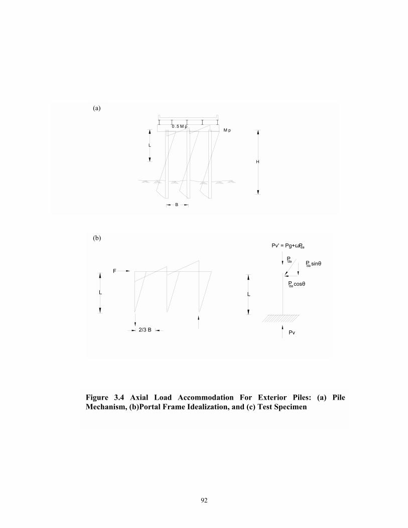
92
Figure 3.4 Axial Load Accommodation For Exterior Piles: (a) PileMechanism, (b)Portal Frame Idealization, and (c) Test Specimen
(c)
H
L
B
M pM p0 .5
L
F
2/3 B
L
Pda sinθPda
P cosθda
Pv
Pv' = Pg+ωPda
(a)
(b)

93
BL5.1
FT ==υ
and substituting equations (3.1) and (3.3) in equation (3.2) gives:
FPP gv υ+=
in which vP = the total applied vertical load on the exterior pile; Pg = the gravity load on pile; and
υ = coefficient relating the additional vertical force to the horizontally applied load.
Consider now a laboratory modeling for this physical situation. There are three possible
experimental setups to carry out the additional tensile uplift, these are explained in what follows:
Method 1: Inclined Actuator:
One possible setup to carry out the additional tensile uplift is to fully incline the horizontal
actuator to account for both the horizontal load F and the additional vertical thrust T. In this case
the angle of inclination necessary is:
υ=θ −1d tan
The axial load Pg is applied through the vertical actuator and is held constant to simulate the
constant gravity load (figure 3.3). The total reaction force in the pile specimen is the sum of the
two actuator components:
ddagv sinPPP θ+=
where daP = force applied by inclined actuator. The main advantage of this setup is that it can
directly accommodate vertical force changes including tension uplift.
However, in most cases, one may be restricted to another angle aθ that is dictated by the
space available in the laboratory.
(3.5)
(3.6)
(3.3)
(3.4)

94
Method 2: Horizontal Actuator with Variable Vertical Force:
One way to overcome the laboratory space limitation problem is to use a horizontal actuator
operating in displacement control and the vertical actuator operating in load control. The variable
axial load can be accommodated as follows:
hagv PPP ω+=
where ω= a proportionality factor that adjusts the fraction of load transferred from the lateral
actuator to the vertical actuator and haP = force applied by horizontal actuator.
Method 3: Hybrid Setup:
The previous two methods can be combined to obtain the third approach which can be applied
under any laboratory room restriction. In this setup the horizontal actuator is inclined with the
available angle aθ and operates in displacement control. The vertical actuator operates in load
control through an algorithm that relates its load to the inclined actuator load. This can be
demonstrated in what follows.
The vertical prototype applied load can be expressed as:
adavgv sinPPFPP θ+=υ+= ′
where aθ = available inclination angle to fit the space in the laboratory; and vP ′ = the force
transferred from the vertical actuator to the specimen, can be quantified as:
dagv PPP ω+=′
The horizontal applied load can be evaluated as:
ada cosPF θ=
(3.8)
(3.9)
(3.10)
(3.7)

95
By substituting equations (3.8) and (3.9) into (3.7) and simplifying, an expression for the
coefficient ω is obtained:
θ−θυ=ω sincos
Therefore the vertical actuator force vaP can be evaluated as:
vva PP ′λ=
where λ = coefficient to account for the effect of the lever beam. To operate the vertical actuator
according to the relationship of equation (3.11), the actuator analog control system required input
from the load cell of the lateral actuator. This load cell value is then multiplied by the value ω.
A fixed offset is employed by the vertical actuator controller to account for the gravity load.
The aforementioned procedure was employed in the experiments conducted for the
present study. The lateral actuator was inclined for exterior piles in pile bent experiments to aθ =
024 , and for pile foundation experiments this angle was set to 044 .
3.4 MATERIAL TESTS
Four steel coupons were cut from the pile flanges for the evaluation of its material
properties. The specimens were constructed according to the ASTM standard dimensions for
tension testing of metallic materials. A tension test was conducted for each specimen in an axial
MTS 445 kN closed-loop servocontrolled hydraulic test system figure 3.5. The results of the
stress-strain behavior for each specimen are shown in figure 3.6. However, the plots do not
represent the entire loading history of the coupon test. In order to prevent damage to the
extensometer, it was necessary to remove it prior to fracture of the specimen. Therefore, the
(3.11)
(3.12)

96
Table 3.1- Results of Flange Steel Coupon Tests
Specimen
Number
Yield
Strength
(MPa)
Ultimate
Strength
(MPa)
sE
(GPa)
shE
(MPa)
shε
1 315 485 199 2430 0.0112
2 315 471 197 2270 0.0109
3 317 465 190 2390 0.0117
4 314 477 185 2630 0.0118
Average 315 475 193 2430 0.0114

97
Figure 3.5 Photograph Showing Coupon Specimen under Tension Test

98
Figure 3.6 Coupon Test Results
SPECIMEN #1
0
50
100
150
200
250
300
350
400
450
0 10 20 30 40 50 60Strain (x 103 m/m)
Stre
ss (M
Pa)
SPECIMEN #2
0
50
100
150
200
250
300
350
400
450
0 10 20 30 40 50 60Strain (x 103 m/m)
Stre
ss (M
Pa)
SPECIMEN #3
0
50
100
150
200
250
300
350
400
450
0 10 20 30 40 50 60Strain (x 103 m/m)
Stre
ss (M
Pa)
SPECIMEN #4
0
50
100
150
200
250
300
350
400
450
0 10 20 30 40 50 60Strain (x 103 m/m)
Stre
ss (M
Pa)

99
ultimate strength of the steel was computed using the ultimate load on the coupon not the final
value on the plot. Other steel properties derived from these tests are shown in table 3.1.
The ultimate compressive strength of the concrete was determined from the results of three
150mm x 300mm-cylinder tests. Results for the various stages during the experimental program
conducted in the present study are shown in table 3.2.
3.5 CONSTRUCTION OF TEST SPECIMENS
The test specimens were constructed with ready-mix concrete, with a specified 28-day
concrete strength of 32 MPa and Grade 60 (414 MPa) steel reinforcement. The HP10x42 piles
were obtained from a local pile driving company. The piles had experienced driving stresses but
were otherwise unused. Typical pile driving procedure involves driving the pile to the required
depth, then cutting the exposed length to achieve the proper height. The sections left over from
this operation were employed as test specimens for this study.
3.5.1 Strong Axis Bending Specimens
Three pile specimens were used for this experimental study. However, instead of
fabricating three separate pile-to-pile cap specimens, all three piles were embedded into the same
pile cap at different spacing. Several vertical ducts made of 38mm PVC pipe were built into the
pile cap in order to provide access for anchor bolts. By using certain combinations of these ducts,
the anchor points for the specimen could be changed to allow the piles to be tested individually.
The resulting test specimens consisted of a full-size cap beam with three HP 10x42 piles as
shown in figure 3.7. The selected piles are typical of what is commonly used in construction
practice. The arrangement of the longitudinal and transverse reinforcement, the embedment length
of the pile, and the cross-sectional area of the pile cap are typical dimensions taken from design
drawings of representative structures. The longitudinal reinforcement on the pile side of the cap
beam consists of a pair of 28 mm diameter (#9) bars spaced at 125 mm centers on each side of the

100
Table 3.2 Results of 150mmx300mm Cylinder Tests
Test ID Spec. # 28 Day Comp.
Strength (MPa)
1 32.4
2 41.7
3 37.3
Strong Axis Bending Pile Bent Specimens
'cf 37 MPa
1 31.8
2 28.6
3 30.2
Pile bent Specimens Tested Along Weak Axis
Bending & Pile Foundation Specimens Tested
Along Strong & Weak Axes Bending
'cf 30 MPa
1 32.3
2 30.7
3 31.30
Retrofit For Pile Bents Tested Along Strong Axis
Bending
'cf 32 MPa
1 33.5
2 31.3
3 32.4
Retrofit for Pile Foundation Specimens Tested
Along Strong & Weak Axes Bending
'cf 32 MPa
'cf = Average compressive Strength of Three Specimens

101
Figu
re 3
.7 G
eom
etry
and
Rei
nfor
cem
ent F
or S
tron
g A
xis P
ile B
ent S
peci
men

102
Figure 3.8 Construction Photos for Strong Axis Specimens (a)Reinforcement Cage, and (b) Formwork

103
embedded pile. The bottom row consists of four 28 mm diameter (#9) bars equally spaced at 200
mm. The longitudinal bars were hooked at the ends to provide additional confinement of the
concrete at the extremities of the beam. Shear reinforcement consisting of 12 mm diameter (#4)
stirrups were placed approximately 200 mm apart along the length of the cap beam, with
appropriate gaps at the pile locations. Confining reinforcement for interior piles consisted of two
12 mm diameter (#4) stirrups with a 200 mm spacing over the embedment length. The exterior
piles utilized two 16 mm diameter (#5) hoops which enclosed the aforementioned hooked
longitudinal bars and were extended past the pile a distance equal to the development length of the
16 mm diameter (#5) bar. Photographs of the reinforcement cage for this specimen are shown in
figure 3.8.
During construction of the pile cap beam, the H-piles were supported by a steel framework,
which maintained the load and proper alignment of the pile in the cap beam while the concrete
cured. For each test, high alloy prestressing (DYWIDAG) threadbars were inserted through the
anchoring ducts and into the laboratory strong floor. The bars were then prestressed to provide the
necessary foundation reactions. Following a test, the pile was remounted back in its location, using
the framework and any damage to the concrete cap beam was repaired prior to retrofitting.
3.5.2 Pile Bents Tested Along the Weak Axis of Bending
The same design reinforcement and specimen dimension used for preparing the strong
axis bending cap beam specimen were also utilized for the construction of the weak axis bending
specimen. Two pile specimens were used for this experiment study representing an interior pile
with a constant axial load and an exterior pile with a varying axial load.
The upper longitudinal reinforcement of the cap beam consisted of two 28 mm diameter
(#9) bars spaced at 125 mm. The bottom row consisted of four 28 mm diameter (#9) bars equally
spaced at 200 mm. The stirrups consisted of 12 mm diameter (#4) hoops spaced at 200 mm along
the length of the cap beam. The confining reinforcement consisted of two 12 mm diameter (#4)
stirrups spaced at 150 mm along the embedment depth of the pile.

104
Figure 3.9 Reinforcement and Geometry of Weak Axis Experiment Specimen
w1 w2

105
Figure 3.10 Photos of Weak Axis Specimens during construction showing: (a) Formwork, and (b) Reinforcement Cage

106
The pile specimens were provided with the bearings shown in figure 3.9, to provide the rotation
adequacy for the lever beam relative to the pile, during the test through its sole plate, and to
preserve more lever arm. The cap beam was supplied with six vertical ducts made of 38 mm PVC
pipe. Combinations of these ducts provided four anchor points, to attach the cap beam to the
laboratory strong floor. High alloy prestressing (DYWIDAG) threadbars were used to post-
tension the reinforced concrete cap beam portion of the specimen to the laboratory strong floor.
During the construction of the wooden boxing for the pile cap beam, a wooden
framework was also constructed to keep up the proper alignment of the pile in the cap beam
while the concrete is poured in. Photographs for this wooden framework as well as the
construction of the specimen are shown in figure 3.10.
3.5.3 Pile Foundation Specimens
Figure 3.11a illustrates a typical piled foundation prototype for an exterior bridge
foundation, taken from design drawings of FHWA. As shown in the figure, an exterior pile in a
pile group can be exposed to seismic load along its strong and weak axes directions. Moreover,
the tension uplift during cyclic loading may be a major factor that can affect its performance.
Based on this criterion, the experimental program for the piled foundation in this study included
testing two exterior piles along the strong and weak axes. On the basis of the prototype (Figure
3.11), one cap beam was constructed to accommodate both cases. Some slight modifications
were introduced to the model as follows.
Although the bridge foundation design shown in figure 3.11 utilized one layer of mesh
reinforcement at the bottom of the foundation, some other drawings utilized an additional layer
at the top. Consequently, for the present study, two layers were used in the design of model
specimen.
The hatched area in figure (3.11c) was employed to design the model specimen.
Therefore the transverse steel was welded to a L2XL2X3/8 angle to achieve the continuation
adequacy purposes of the steel in that direction (see figure 3.12).

107
Figu
re 3
.11
Bri
dge
Prot
otyp
e an
d R
atio
nale
use
d fo
r de
visi
ng th
e M
odel

108
Figu
re 3
.12
Geo
met
ry a
nd R
einf
orce
men
t of P
ile F
ound
atio
n as
Bui
lt Sp
ecim
ens

109
It was decided to anchor the specimen to the laboratory floor using high alloy prestressing
(DYWIDAG) threadbars that would be inserted through an anchor beam. Therefore, in designing
the specimen, only horizontal ducts made of 38mm PVC pipe were built into the pile cap for the
purpose of lifting the specimen during transferring from the workshop to the test setup location.
The pile specimens were provided with the same type of bearings used for the pile bent
weak axis experiment, for the same purposes mentioned earlier. Photographs of the construction
of this specimen are shown in figure 3.13.
3-6 EXPERIMENTAL SETUPS
3.6.1 Pile Bent Experiments
The test rig employed for these experiments is shown in figures 3.14 and 3.15. The
specimens were anchored to the strong floor to provide restraint against both translational and uplift
during testing. Lateral load was provided by a 250kN capacity ± 300mm stroke MTS servo-
controlled hydraulic actuator. This actuator, which was operated in displacement control, was
attached directly to the pile with a pin connection, for the strong axis experiments, allowing
rotation about only one axis, as shown in figure 3.15(a). It was, however, attached to the rocker
bearing above the pile, in the case of weak axis experiments, through an adapter section, as shown
in figure3.15 (b) to provide additional lever arm length. The other end of the actuator was bolted to
a rigid reaction frame. The test rig did not employ any bracing to actively prevent out-of-plane
motion of the pile. However, the pin connection at the pile provided adequate passive restraint
against these undesirable displacements.

110
Figure 3.13 Construction of the Pile Foundation Specimen Showing: (a) Formwork, and (b) Reinforcing Cage

111
Figure 3.14 Test rig For Pile Bent Specimens

112
Figure 3.15 Pinned Connection of The Lateral Actuator to ThePile Bent Specimen: (a) Strong Axis Experiment, and (b) WeakAxis Experiment

113
Axial load was provided by a 350kN capacity ± 50mm stroke Parker servo-hydraulic
actuator operated in load control. The actuator load was applied to the pile through a W10X77
lever beam, shown in figure 3.15(b). A 32mm diameter high strength prestressing (DYWIDAG)
threadbar provided the reaction at the other end of the lever beam. Both this bar and the actuator
were anchored to the strong floor with rocker bearings that allowed the lever beam to move with
the pile during the course of the tests. The constant gravity load was taken as 200 kN resulting in
the following relationship according to equations (3.9) and (3.12):
In case of strong axis experiments, a rocker bearing assembly was also located between the
pile and lever beam. This bearing allowed the lever beam to rotate relative to the pile while
transmitting the necessary load. The sole and web plates of the bearing used for weak axis
experiments were employed for the same purpose. The testing procedure employed a quasi-static,
cyclic lateral load that followed a sinusoidal wave form. An MTS 436 Controller was used for the
hydraulic supply providing the frequency control for the test. MTS 406 Controllers were used for
each actuator.
3.6.2 Pile Foundation Experiments
Figure 3.16 illustrates the test rig employed for the testing of the as built specimens. Lateral load
was provided by an 1100kN MTS hydraulic actuator anchored to the reaction frame at an angle
of 05.42 to the horizontal and connected directly to the specimen. A photograph of the
connection is shown in figure 3.17a. The vertical load due to gravity was provided by the 350kN
capacity ± 50mm stroke Parker servo-controlled hydraulic actuator, operated in load control and
connected to the W10X77 lever beam. The W10X77 gravity load beam was anchored to the strong
floor at one end using a 32mm diameter DYWIDAG bar. The force in the 1100 kN actuator
actively controlled the vertical actuator. The constant gravity load was taken as 135 kN. Therefore:
kN)P609.05.37(P163P davva ' +==

114
Figu
re 3
.16
Tes
t Rig
Em
ploy
ed F
or A
s Bui
lt P
ile F
ound
atio
n Sp
ecim
ens

115
(a)
(b)
Figure 3.17 The Test Rig of the as Built Pile Foundation Specimens Showing :(a) Connection Between Actuator and Specimen, and (b) Anchor Beam

116
according to equations (3.9) and (3.12), the following relationship was used to control the vertical
actuator
=′= vva P167P (59 + 0.121 daP ) kN
The vertical actuator increased the axial force in the column when the lateral actuator was
pushing and decreased it during pull.
A W10X88 steel beam was used to anchor the specimen to the strong floor to provide the
sufficient restraint against translation and uplift during the tests. The beam was anchored at one
end to the strong floor using two 25 mm high alloy prestessing (DYWIDAG) threadbars. It was
anchored from the other end to the strong floor using one 32mm high alloy prestessing threadbar.
The two 25mm bars were prestressed to 90 kN each. This prestressing force resulted in 480 kN
axial anchoring force on the specimen.
The test rig used for the as-built specimen was slightly modified for the retrofitted
specimen. As shown in figure 3.18 the specimen is attached to the bearing to preserve the same
lever arm before and after retrofit. On the basis of the retrofit philosophy adopted in this study, a
ductile steel failure was expected. Accordingly, a maximum horizontal force was estimated as
490 kN to yield the strong axis specimen. Therefore two additional keeper plates of 75mm
thickness were used to attach the actuator to the bearing. A picture of this connection is shown in
figure 3.19a. Assuming a friction coefficient 0.3 between the specimen bottom and the laboratory
floor, then the maximum vertical force necessary for anchoring this specimen is 1630 kN.
Therefore for this setup four 32mm high alloy prestessing threadbars were employed to anchor
the specimen to the floor (figure 3.19b). Those bars were prestressed to a force of 310 kN each.
The resulting anchoring force on the specimen was 1650 kN. Additional restraint precautions
were added in the form of backup beam and backup plate to account for any uncertainty during
the test. The laboratory reaction frame was prone to uplift due to the high uplift force that occurs
when the diagonal actuator is pulling. Consequently, the same methodology adopted for
anchoring the specimen to the laboratory floor was employed to impose additional axial force at

117
Figu
re 3
.18
Tes
t Rig
Em
ploy
ed F
or R
etro
fitte
d P
ile F
ound
atio
n Sp
ecim
ens

118
Figure 3.19 The Test Rig of the Retrofitted Pile Foundation Specimens: (a)Connection Between Actuator and Specimen, and (b) Anchor Beam UnderPrestress

119
(a)
Figure 3.20 The Prestressing Process for the Reaction Frame: (a) Anchor Beam at the Top of the Reaction Frame with High Alloy Prestressing (DYWIDAG) Threadbars, and (b) Prestressing Process Below the Strong Floor

120
the top of the reaction frame. According to the inclination angle of the lateral actuator, 490 kN
uplift force is expected. Therefore, a W10X88 beam seated on a rocker bearing at the top of the
reaction frame as shown in figure 3.20a was used with four 32 mm high alloy prestressing
threadbars to provide the necessary vertical force. In order to achieve this force the high alloy
prestressing threadbars were prestressed to 360 kN resulting in 720 kN at the top of the reference
frame. The prestressing process was conducted, as shown in figure 3.20b, below the strong floor.
3.7 INSTRUMENTATION DATA ACQUISITION AND PROCESSING
3.7.1 Instrumentation
The instrumentation used for the experiments consisted of sonic transducers and load cells
as shown in figure 3.21. The Sonic Transducers (S-T) were MTS "Temposonics" model number
DCTM-4002-1. The Sonic Transducers used for rotation measurements had a stroke of ± 102mm,
while for the measurement of lateral displacements for the pile bent experiments a ± 150mm stroke
was used. Other Sonic Transducers used for pile foundation experiments had strokes of ± 102mm,
± 150mm, and ± 203mm for the lower, middle and upper location, respectively. The load cells
were 500kN and 650kN devices supplied with the MTS and Parker actuators, respectively. Strain
gauges were also used for the pile bent experiments they were Micro-Measurements CEA-06-
125UW-120.
Sonic Transducers were also used to measure displacements of the pile specimens, as shown
in figure 3.22. Three transducers were used for measuring the lateral displacements. They were
placed at top, middle height and bottom of the specimen, 25mm above the concrete cap surface. The
lowest transducer was designed to measure translation of the pile at the connection point. The top
transducer was placed at the same height as the centerline of the lateral actuator. This instrument
provided the input signal for the lateral actuator, which operated in "displacement control". The
middle temposonic was located outside the potential plastic hinge zone and was used to gather
additional displacement data for the pile. Pile foundation experiments employed an additional Sonic
Transducer at the same height of the point of action of the inclined actuator. It was used to

121
(a)
(a) INTERIOR PILE
Figure 3.21 Instrumentation Configuration
(b) EXTERIOR PILE
S-T FOR LOADCONTROL
REFERENCEFRAME
S-T FORMEASURINGPULL-OUTOF THE PILE

122
Figure 3.22 Instrumentation: (a) Lateral Displacement S-T, and (b) S-T for Measuring The pile Curvature and Pull Out

123
compare its outcome with the outcome from the displacement control sonic transducer. The middle
sonic transducer was excluded from the pile foundation retrofitted specimen, as the length of the
specimen was reduced to 686 mm. All horizontal temposonics were mounted on a reference frame
which was either anchored to the laboratory strong floor, or to the specimen.
Sonic transducers were also used to measure the rotation and "pull-out" of the pile, as shown
in figure 3.22(b). Two tubular steel sections were clamped to the pile a distance of 610 mm from
the concrete pile cap surface. The sonic transducers were mounted at each end of the tubular
reference frames providing a total of four instruments. During the test, the transducers measured
linear translation, which could then be converted into rotation by accounting for the position of the
transducer relative to the centerline of the pile. By taking the average of the four displacement
values, it was possible to measure the vertical translation or "pull-out" of the pile relative to the cap
beam.
3.7.2 Data Acquisition and Analysis
During the tests of the three pile specimens, an optim Megadac 5533A Data Acquisition
system was used to collect and save the data in an ASCII format. The methods adopted in data
analysis are outlined below.
The force and displacement data were obtained directly from the actuator load cell and
the sonic transducers, respectively. The drifts were calculated using the relation:
L∆
=θ
where, θ = the drift angle; ∆ = displacement of top sonic transducer; and L= height of the pile
measured from the cap beam surface to the transducer location at the centerline of the lateral
actuator.
(3.13)

124
Curvatures and strains were calculated from:
PL
ε=φ
where:
g
p
L∆
=ε
in which p∆ = the algebraic difference of the average readings of each pair of sonic transducers
at each side of the pile; pL = center-to-center distance between the transducers pairs measured
along the longitudinal axis of the cap beam; and gL = gage length.
Evaluation of Damping:
Effective damping ( effξ ) in a structure can be viewed as a combination of equivalent
viscous damping eqξ , and viscous damping inherent in the structure 0ξ (assumed to be constant
value of 0.05). The term eqξ represents the hysteretic damping provided by the nonlinear
performance of the material and can be calculated as (Chopra 1995):
so
Deq E
E41π
=ξ
where DE = energy dissipated by damping (see figure 3.23), and soE = maximum strain energy.
According to figure 3.23a, DE is evaluated as:
( )eff0maxyD KK4E −∆∆=
(3.14)
(3.15)
(3.16)
(3.17)

125
in which, y∆ = yield displacement, max∆ = maximum displacement, 0K = initial stiffness, and
effK = the secant stiffness (figure 3.23b) which can be written in terms of ductility ratio
max( ∆=µ / y∆ ) as:
µ
α−+α= )1(KK 0eff
where α = post yield stiffness ratio. The maximum strain energy can be quantified as:
2KE
2max
effso∆
=
Assuming an overall bi-linear response, as shown in figure 3.23a, the effective damping
due to hysteresis can be determined by substituting equations (3.17) through (3.19) in equation
(3.16) and rearranging, the equivalent viscous damping can be quantified as:
)1(
11)1(2
eq µα+α−
µ
−α−
πη=ξ
where η = efficiency factor defined as:
EPP
cycle
EE
=η
where EPPE = the energy absorbed by a 100% perfect elasto-plastic system, defined according to
the following relationship:
)xx)(FF(E ppnnEPP−+−+ ++=
(3.18)
(3.19)
(3.20)
(3.21)
(3.22)

126
where +nF = the nominal capacity of the system in the push direction; −
nF = the
corresponding value in the pull direction; +px = the plastic component of the displacement in the
push direction; and −px = the corresponding value in the pull direction.
In the present study elastic-perfect plastic behavior will be assumed. Consequently, α is
set to zero and equation (3.20) is simplified to:
µ
−πη=ξ 112
eq
The hysteretic energy absorbed by the system per cycle is given by:
( )1ii
n
1i
1iicycle xx
2FFE −
=
− −
+
=∑
where iF = force in i-th step; and ix = displacement of the same step.
The experimental effective viscous damping is defined according to UBC 1994 as:
maxmax
cycleoeqoeff F
E21
∆π+ξ=ξ+ξ=ξ
where maxF = average of the maximum strength in the forward and reverse loading directions, and
max∆ can be evaluated as the average of the maximum displacement in both loading directions.
(3.24)
(3.25)
(3.23)

127
Keff
∆max
Fmax
Eso
ED
Figure 3.23 Illustrating (a) Bilinear Representation of Cyclic Loops , and (b)Derivation of Effective Stiffness
∆
F
o
yK
maxFα oK
max
effK
∆y
( )
( )( )µα−+α=∆∆
α−α+∆∆
=∴
∆−∆α+∆=∆
=
/1KK
KKKK
KKF
FK
oeff
max
yoo
max
yoeff
ymaxoyomax
max
maxeff

128
Equation (3.20) and (3.25) are employed to evaluate the ductility ratio for different pile-to-cap
connections tested in the present study. Details of these values will be discussed in the next two
sections.
3.8 CLOSURE In this section an experimental modeling strategy for steel H-pile-to-cap connections was
outlined. The dimensions of the specimen were dictated by the anticipated translational plastic
mechanism of the prototype. A method for simulating a variable axial load that accommodates the
tension uplift conditions for exterior piles under lateral cyclic loads was presented. Through this
method, the vertical actuator used to simulate the variable axial load is operated and controlled by
the force output from the lateral actuator. The algorithm used to determine this relationship was
described.
Coupon test results for the steel material used in the experiment as well as the 28 days
compressive strength of the concrete used in the construction of all specimens were mapped. This
was followed by, a description of the steps involved in the design, and construction of different test
specimens.
The experimental test rigs, and instrumentation employed in all the experiments conducted
through this study were explained through the aid of diagrams and photographs. Lastly, the methods
used for analyzing and processing the experimental data were outlined.

129
SECTION 4
EXPERIMENTAL RESULTS FOR "AS-BUILT" SPECIMENS
4.1 SCOPE OF THE EXPERIMENTAL PROGRAM
This section outlines the experimental observations and results of the cyclic lateral load
tests on the steel pile bents and pile foundation specimens. The main objective of these tests was
to determine the performance of "as-built" specimens subjected to different cyclic loading
regimes. These specimens are consistent with present "as-built" bridge practice in the eastern
and central US.
Seven test specimens were investigated during this program to identify their seismic
vulnerability. These specimens are as follows:
• Specimens S1: Strong Axis Interior Pile bent with No Axial Load.
• SpecimenS2: Strong Axis Interior Pile bent with Constant Axial Load.
• Specimen S3: Strong Axis Interior Pile bent with Constant Axial Load.
• Specimen W1: Weak Axis Interior Pile bent with Constant Axial Load.
• Specimen W2: Weak Axis Interior Pile bent with variable Axial Load.
• Specimen PS: Strong Axis Interior Pile foundation with variable Axial Load.
• Specimen PW: Weak Axis Interior Pile foundation with variable Axial Load.
Table 4.1 summarizes the axial loads and drift information for all the "as-built" specimens.
The experimental program consisted of testing the specimens at cyclic drift amplitudes
which ranged from ± 0.5% to 6%. Each of the specimens was tested for a minimum of two
cycles per drift amplitude. Testing was conducted under displacement control where the
specimens were first pushed then pulled. The command signal was provided by an analog
function generator in the form of a positive sine wave with a cyclic period of one-minute.

13
0
Tabl
e 4.
1 Ch
arac
teris
tics o
f A
s-Bu
ilt T
est S
peci
men
s
Spec
ID
Type
G
ravi
t
y Lo
ad
(kN
)
Spec
.
Leng
th
(mm
)
pV
dM
Late
ral
Act
uato
r
Ang
leθ
Ver
tical
Axi
al
Load
Con
trol
Tota
l Axi
al
Load
Max
. Drif
t N
umbe
r of
Cycl
es a
t
Max
. Drif
t
S1
Bent
0
3050
12
.5
0 0
0 5%
2
S2
Bent
25
0 30
50
12.5
0
250
250
6%
10
S3
Bent
20
0 30
50
12.5
24
20
0 +3
.27
daP
200+
4.02
V
5%
10
W1
Bent
25
0 26
16
10.5
0
250
250
6%
10
W2
Bent
20
0 26
16
10.5
35
20
0+2.
72daP
20
0+4.
02V
7.
5%
8
PS
Foun
datio
n 13
5 78
5 3
43
135+
0.27
6 daP
13
5+1.
3V
6%
2
PW
Foun
datio
n 13
5 78
5 3
43
135+
0.27
6 daP
13
5+1.
3V
5%
5
S
= S
trong
Axi
s Ben
ding
W =
Wea
k A
xis B
endi
ng
PS =
Pi
les,
Stro
ng A
xis
PW
= P
iles,
Wea
k A
xis
V =
daP
cos
θ
M
= A
pplie
d m
omen
t
130

131
4.2 GENERAL OBSERVATIONS
Pile Bent specimens (S1, S2, S3, W1, W2) behaved elastically prior to 2% drift.
Pile bents oriented along the strong axis direction (S1, S2, S3) sustained higher drifts, and
damage of the connection was concentrated mainly in the concrete cap beam. Pile bents
tested along the weak axes bending (W1, W2) showed high performance in terms of
ductility and energy absorption. Pile foundation specimens (PS, PW) behaved elastically
prior to 0.5% drift and experienced fracture in the concrete cap in a brittle failure mode
during the 2% drift .
To allow comparison of plots of the experimental results and the theoretical
predictions, dashed lines representing the plastic moment capacity, and yield capacity are
superimposed on the force -displacement plots. The theoretical yield and plastic moment
capacities were defined using the well known relationships for bending moment:
SfLVM yyy ==
and
PyPP ZfLVM ==
in which, yf = the steel pile section yield stress; L = the lever arm; S = the steel pile
section modulus; PZ = the plastic modulus of the steel pile section; and Vp, Vy are the
plastic and yield shear force, respectively. Those forces, however, were reduced or
increased to account for the P- ∆ for specimens tested under varying axial loads.
The experimental "yield" displacement is defined as an extrapolation to 1.0 Vp of
the observed displacement at 0.75 Vp. The average value obtained from the forward and
reverse directions of the first cycle of loading is used to define the experimental " yield "
displacement.
(4.1)
(4.2)

132
4.3 Force-Displacement Results
4.3.1 Specimen S1: Strong Axis Interior Pile with No Axial Load
This specimen was tested under reverse cyclic lateral load along its strong axis; no
vertical (axial) loads were applied to the pile. The loading was applied through a 250 kN
MTS servo-hydraulic actuator operated in displacement control, and mounted at a height of
3050 mm above the concrete base surface. This was to investigate the likelihood of the pile
"walking out" of its socket when the adhesive bond between the concrete in the cap beam
and the steel pile was lost.
This specimen was tested with two reversed cycles at drift amplitudes of ± 0.5 %,
± 1%, ± 2%, ± 3% , ± 5% and with four reversed cycles at ± 4%. The most significant
finding of this test was that even without axial load, the yield moment of the pile was
exceeded and the plastic capacity of the section was nearly achieved (see figure 4.1).
Yielding of the section first occurred just prior to the 2% drift level. At this point, damage
to the connection was concentrated mainly in the pile with diagonal yield lines visible on the
whitewashed flanges. Upon higher drifts, the damage occurred entirely in the concrete cap
beam. Shear cracks formed in the concrete starting at the flange tips, emanating away from
the pile at approximate 045 toward the edge of the beam. These cracks propagated down
the side of the cap beam crossing each other about the mid-depth of the beam. The marked
"pinching" of the force displacement plot is indicative of concrete crack propagation, which
progresses by alternately opening and closing during the course of cyclic testing. Gaps
formed between the face of the steel flanges and the adjacent concrete as the concrete
crushed due to the high local bearing stresses. The "pinching" shown in figure 4.1 evidenced
the significant cracking of the cap beam. The cracks opened and closed during the course of
testing. On the pull side of the third cycle at the 4% drift level, a general shear failure
occurred in the concrete on the tension flange side. The concrete near the flange became so
loose that it could not provide sufficient bearing resistance for the flanges and the moment
capacity dropped dramatically. Only two cycles at the 5% drift level were performed, as at
that stage the loss of the connection strength was noticeable. A photograph of specimen S1
at the end of the test is shown in Figure 4.2.

133
Figure 4.2 Connection S1 after Being Tested
Figure 4.1 Pile Specimen S1: Lateral Load-Displacement Relationship
-100
-80
-60
-40
-20
0
20
40
60
80
100
-180 -160 -140 -120 -100 -80 -60 -40 -20 0 20 40 60 80 100 120 140 160 180Lateral Displacement (mm)
Late
ral L
oad
(kN
)-6.0 -5.0 -4.0 -3.0 -2.0 -1.0 0.0 1.0 2.0 3.0 4.0 5.0 6.0
Column Drift Angle (%)
Pile YieldPlastic Strength
push
pull
P = 0
V -V
L=3050mm

134
4.3.2 Specimen S2: Strong Axis Interior Pile with Constant Axial Load
In addition to the lateral cyclic loading along the strong axis of the specimen, this
specimen was also tested under a constant axial load. The 350 kN Parker servo-hydraulic
actuator applied a constant axial load of 47 kN which was transferred through the lever
beam arm action to the pile. This resulted in a 250 kN axial force being transferred to the
pile. This axial force is considered to be representative of the gravity load the bridge
superstructure transfers to a steel pile within a bent. Specimen S2 was expected to perform
somewhat better than specimen S1 as the axial load inhibited the "walk-out" phenomenon.
Specimen S2 was tested with two reversed cycles at drift amplitudes of ± 0.5%,
± 1%, ± 2%, ± 3%, ± 4%, ± 5% concluding with ten cycles at ± 6%. The force-
displacement behavior is shown in figure 4.3. The specimen behaved in an elastic manner
prior to the 2% drift level at which point yielding occurred in the steel. Most of the
deformation occurred in the steel pile for this test, and the gradual increase in capacity was
attributed due to the steel strain hardening upon cyclic loading. Because the connection still
had a large moment capacity remaining after the 5% drift test, it was decided to perform the
constant, high amplitude test phase at the 6% drift level. Ten cycles were completed at 6%
drift until failure in concrete was reached. A general observation for this specimen is that its
hysteretic performance showed much more energy dissipation per cycle than specimen S1
(i.e. less "pinching of the hysteresis loop).
There was a balance between the moment capacity of the steel pile and the strength
of the connection joint itself. Providing a compressive axial load increased the strength of
the connection. The axial load effectively held the steel into the socket formed in the
concrete, and created a moment opposing the overturning moment induced by the lateral
load around the pile embedded tip. Once relative displacement occurred between the steel
and concrete, the bond was rapidly reduced. The concrete surface at the interface was
polished smooth by the slipping surfaces of the two materials (this effect was observed
when the pile was removed following the test in order to repair the cap beam). While the
adhesive bond remained intact and the connection strength

135
Figure 4.3 Pile Specimen S2: Lateral Load-Displacement Relationship
-100
-80
-60
-40
-20
0
20
40
60
80
100
-200 -150 -100 -50 0 50 100 150 200LATERAL DISPLACEMENT (mm)
LATE
RAL
LO
AD (k
N)
Column Drift Angle (%)
Pile Yield
Plastic Strength
1 6543-2-3-4-5 2-6 -1
V -V
P = 250 kN
L=3050 mm

136
)M( j exceeded the strength of the pile, the majority of the overall deformation arose
primarily through ductile deformation of the steel. However, once the adhesive bond was
lost, such that pj MM < , the rocking motion of the steel pile rapidly degraded the
concrete, forming cracks which eventually failed the connection (see Figure 4.4). Even
though the plastic moment capacity of the steel pile was achieved initially, significant
cracking and spalling of the concrete pile cap beam occurred with continual cyclic loading
and resulting in strength degradation.
4.3.3 Specimen S3: Strong Axis Exterior Pile with Variable Axial Load
Specimen S3 shown under load in Figure 4.5 was tested along the strong axis, under
a variable axial load to investigate the effect of tension uplift on an exterior pile in a bent.
The loading regime consisted of a 250 kN MTS servo-hydraulic actuator inclined at 024 to
the horizontal pushing downwards, together with a 350 kN Parker servo-hydraulic vertical
actuator pulling downwards. The algorithm described in section 3.3 and governed by the
equations shown in table 4.1 was employed to simulate the variable axial load during lateral
cyclic loading.
This specimen was tested with two reversed cycles at drift amplitudes of ± 0.5%,
± 1%, ± 2%, ± 3%, ± 4% concluding with ten cycles at ± 5%. The axial load varied
between the net tensile force of 45 kN to a net compressive force of 490 kN, the axial load at
zero displacement being 200 kN. For the small axial loads of the pull direction, the pile
behaved similarly to the first specimen, as shown in figure 4.6. Crack closure was strongly
evident for the return cycles at the lower lateral load values. For the push direction
however, the behavior more closely followed that of the second pile. Higher lateral loads
were needed to achieve the same drift levels in comparison to the pull direction. Yielding
of the steel was pronounced at the 2% drift level with a load plateau evident at higher drifts.
The second phase of testing consisted of ten cycles at 5% drift. Interestingly, very
little strength degradation was seen for this phase of the test. This high ductility can be
attributed to the limited cracking damage in the concrete cap beam. The cracks formed were

137
Figure 4.4 Connection S2 after Being Tested: Top shows the Gap created between the Steel Pile and Cap Beam; Bottom shows Side View

138
Figure 4.5 Specimen S3 under Test Along its Strong Axis

139
stable and did not propagate over a wide area, as in the first two tests (see the photograph
of the specimen after test in figure 4.10). The slightly higher degree of confining
reinforcement on the end of the cap beam, as compared to the interior piles, is responsible
for maintaining the integrity of the concrete during the cyclic tests. Due to shortcomings of
the test rig, the test of Pile Specimen 3 was not continued sufficiently to reach the ultimate
failure capacity of the connection.
Figure 4.9 plots a lateral load-axial load interaction diagram for Specimen S3. The
ultimate strength interaction relationships assumed for I-section shapes bending along its
strong axis is:
in which pcF = the lateral load capacity for a given axial load, P, pF = the unmodified
lateral load capacity given by pp MF = /L where pM =plastic moment capacity and L =
cantilever column height of the pile. The experimentally observed result is the inclined line
adjacent to the vertical axis. Evidently, a maximum vertical compression load of 490 kN
and a tension load of 45 kN were attained. The axial load required to yield the gross cross-
section of the pile, YP , is 2510 kN.
4.3.4 Specimen W1: Weak Axis Interior Pile with Constant Axial Load
This specimen was tested to study the cyclic performance of interior piles oriented
along the weak axis. The specimen was tested before under the same conditions as specimen
S2. The lateral actuator was mounted at 2616 mm above the concrete base surface and
connected to an adapter steel section, which was connected to the specimen. This specimen
was expected to perform better than specimen S2, as the connection efficiency in this case is
higher than in case of strong axis orientation. Figure 4.9a shows this specimen under test.
−=
yp
pc
PP118.1
FF
(4.3)

140
-3,000
-2,000
-1,000
0
1,000
2,000
3,000
-100 -80 -60 -40 -20 0 20 40 60 80 100
LATERAL LOAD (kN)
AXIA
L LO
AD (k
N)
compression
tension
PushPull
Plastic CapacityYield
-100
-80
-60
-40
-20
0
20
40
60
80
100
-200 -150 -100 -50 0 50 100 150 200
LATERAL DISPLACEMENT (mm)
LATE
RAL
LO
AD(k
N)
Drift Angle (%)
push
pull
joint opening
joint closing
54321 6-6 -5 -4 -3 -2 -1
L=3050 mm
V -V
P = (200+4.02 Kn)
Figure 4.7 Experimental and Theoretical Lateral Load-Axial Load Interaction Diagram For Specimen S3
Figure 4.6 Pile Specimen S3: Lateral Load-Displacement Relationship

141
Figure 4.8 Connection S3 after Being Tested

142
Specimen W1 was tested with two reversed cycles at drift amplitudes of ± 0.5%, ± 1%,
± 2%, ± 3%, ± 4% , ± 5% concluding with twelve cycles at ± 6% drift. The steel
performance rather than the concrete behavior governed the overall behavior of the
connection. Therefore, the connection showed a perfect performance in terms of energy
absorption and ductility (see figure 4.10).
The maximum lateral force attained for this specimen was 48 kN, and 46 kN in the
push and pull directions, respectively. The expected performance of the steel material under
cyclic loading was achieved during this experiment. Up to 2% drift the specimen behaved in
an elastic fashion. Yielding occurred first at the push of the first cycle of 3% drift, at the
flanges, through a distance extended 100 mm above the concrete cap beam surface. This
yielding extended to another 100 mm during the 4% and 5% drifts. This was accompanied
with a noticeable work hardening of the steel material. Local buckling was pronounced in
both flanges during the pull of the second cycle of the 6% drift. At this point it was noticed
that the connection could undergo more cycles until the strength degradation of the steel
material is achieved. Therefore, it was decided to carry out twelve more cycles of 6 % drift.
Strength degradation was noticeable at the third cycle and continued through the rest of the
cycles. A photograph of the connection after the test is shown in figure 4.11.
4.3.5 Specimen W2: Weak Axis Interior Pile Under Variable Axial Load
This specimen was tested along the weak axis under the same conditions as
Specimen S3 to investigate the effect of tension uplift on exterior piles oriented on that
direction. The specimen was less in height than specimen S3. Accordingly, the lateral
actuator was mounted at an 035 angle, and the vertical actuator-lateral actuator load
relationship was modified to accommodate the difference in inclination and achieve the
same loading conditions as specimen S3. Figure 4.9b shows this specimen under test.

143
(a)
(b)
Figure 4.9 of Specimens W1 and W2 under Test Along their Weak Axes (a) Specimen W1, and (b) Specimen W2

144
Figure 4.11 Connection W1 after Being Tested
Figure 4.10 Pile Specimen W1:Lateral Load -Displacement Relationship
-7 -6 -5 -4 -3 -2 -1 0 1 2 3 4 5 6 7
-60
-40
-20
0
20
40
60
-200 -150 -100 -50 0 50 100 150 200
LATERAL DISPLACEMENT(mm)
LATE
RAL
LO
AD (k
N)
DRIFT ANGLE %
Plastic Strength
Pile Yield
V -VP=250 kN
L = 2616 mm
PUSH
PULL

145
The specimen was tested with two cycles of drift at levels of ± 0.5%, ± 1%, ± 2.5%,
± 3.5%, ± 5%, ± 6%, and 8 cycles at ± 7.5% (see figure 4.12). The overall performance of
the connection was governed by the steel behavior up to 6% drift. Most of the deformation
occurred in conforming to typical steel behavior. The maximum force attained in the push
direction was 51kN. The maximum pull force, however, was 64 kN.
The specimen behaved in an elastic fashion prior to 2.5 % drifts. Yielding of the
flanges, in the push direction, was noticeable at the first cycle of 2.5 %. This was
characterized by some diagonal striations on the white washed flanges. During the 3.5%
drift these striations continued to spread in the flanges through a 150mm length above the
concrete cap beam surface. As shown in figure 4.13, work hardening was observable to the
end of the second cycle of the 5% drift. At this drift level, yielding was noticeable over a
distance of 350mm from the concrete surface. Local buckling of the flanges took place
during the push of the second cycle of the 6% drift. At this point it was obvious that strength
degradation of the steel material started to occur. Two more cycles were tried at 7.5% drift.
Two Cracks appeared in the concrete, during the push of the first cycle at that drift, and
emanated from the pile towards the transverse cap beam, and propagated down to the lower
concrete cap beam surface. A sudden loss of strength took place in hysteretic loops
companioning the crack growth, during the pull of this cycle. Other cracks emanated from
these two basic cracks during the second cycle at 7.5% drift, and pinching of the loops was
noticeable. Six more cycles were conducted at that drift level. The cracks opened and closed
during the course of these drifts. It was obvious by the end of the sixth drift that the
connection reached its ultimate capacity, and failure occured. Photographs of this
connection after the experiment are shown in figure 4.15.
The ultimate strength interaction relationships for I-section shapes bending along its
weak axis is governed by the following equation:
−=
2
yp
pc
PP1
FF
(4.4)

146
Figure 4.12 Specimen W2 Under 7.5% Drift During Testing
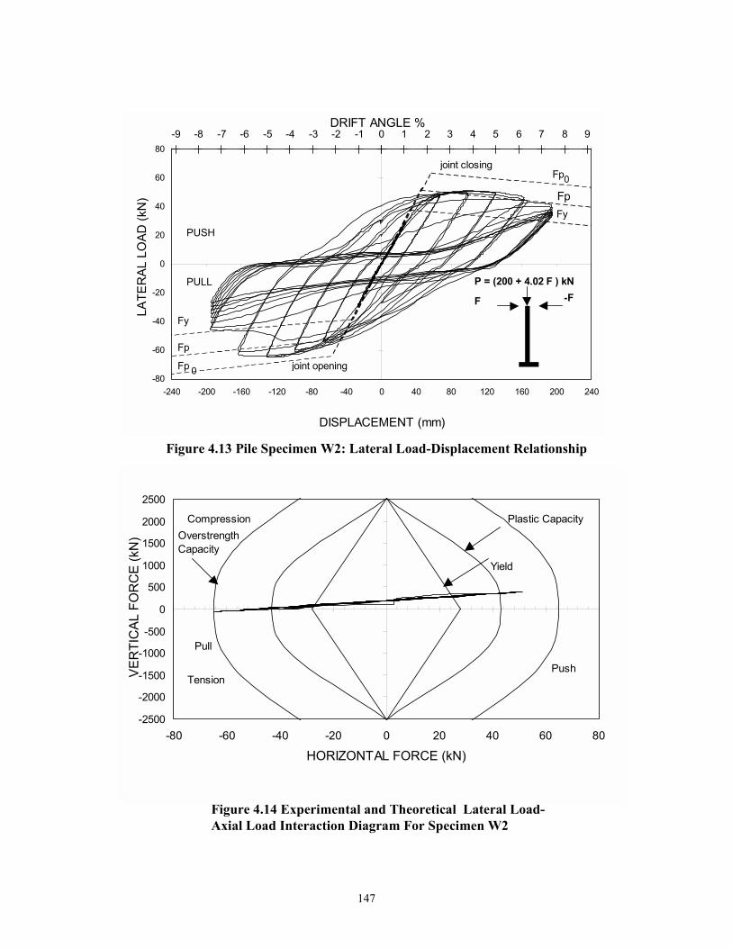
147
Figure 4.13 Pile Specimen W2: Lateral Load-Displacement Relationship
Figure 4.14 Experimental and Theoretical Lateral Load-Axial Load Interaction Diagram For Specimen W2
-2500
-2000
-1500
-1000
-500
0
500
1000
1500
2000
2500
-80 -60 -40 -20 0 20 40 60 80
HORIZONTAL FORCE (kN)
VER
TIC
AL F
OR
CE
(kN
)
Compression
TensionPush
Pull
Yield
Plastic CapacityOverstrength Capacity
-9 -8 -7 -6 -5 -4 -3 -2 -1 0 1 2 3 4 5 6 7 8 9
-80
-60
-40
-20
0
20
40
60
80
-240 -200 -160 -120 -80 -40 0 40 80 120 160 200 240
DISPLACEMENT (mm)
LATE
RAL
LO
AD (k
N)
DRIFT ANGLE %
Fy
0
Fp
Fp
FyFp
Fp 0
joint closing
joint opening
F -FP = (200 + 4.02 F ) kN
PUSH
PULL

148
Figure 4.15 Damage Occurred to Connection W2 after Test.Top Photograph shows an end view. Lower Photograph Shows a side view including the damage occurred to the cap beam

149
Figure 4.14 plots a lateral load-axial load interaction diagram for Specimen W2. The
maximum compression and tension forces 397 kN, and 65 kN respectively were achieved
during the push of the first cycle at 6% drift companioning, the extreme work hardening of
the steel material. This specimen showed a superior performance compared to specimen S3,
tested under same conditions along the strong bending axis, as the maximum tension uplift
force was higher in this case without any detectable walking out of the pile from the socket
4.3.6 Specimen PS : Strong Axis Exterior Pile with Variable Axial Load
Specimen PS represents an exterior pile foundation with a typical pile cap
connection. The specimen was tested along its strong axis orientation with a variable axial
load considered to be representative for this class of piles as shown in Figure 4.16a. The
1100 kN MTS servo-hydraulic actuator operated in displacement control and mounted at an
angle of 043 was used to induce the lateral load. The 350 kN Parker servo-hydraulic vertical
actuator induced the variable axial load. Both actuator outputs are related to induce a total
axial load governed by the equation shown in Table 4.1. The specimen had a clear height of
785 mm ( )3VdM p = above the concrete base surface.
This specimen was tested with two reversed cycles at drift amplitudes of ± 0.25%,
± 0.5%, ± 1%, ± 2%, ± 3% , ± 4% and 5% drift. It exhibited the most inferior
performance among all other specimens tested during the course of this study. The 285
kN theoretical yield force of the steel pile section was not attained.
The specimen behaved linearly prior to the 1% drift amplitude. A sudden brittle
failure of concrete was pronounced at the push of the first cycle at the 2% drift. This
failure was characterized by two wide cracks formed in the concrete starting at the flange
tips and propagated away from the pile towards the beam transverse edge to a 450 mm
distance above the concrete lower surface. During the second cycle at the 2 % drift
amplitude, a second transverse crack propagated along the beam transverse edge to
connect the two points where the other two cracks stopped.

150
Figure 4.16 Specimen PS and PW under Test Along their Strong and Weak Axes (a) Specimen PS, and (b) Specimen PW
(a)
(b)

151
This failure was accompanied with a 30% loss of strength in the hysteretic load-
displacement loops (see figure 4.17). Cracks widening growth continued during the
course of the 3% drift and the opening of the cracks was noticeable during the push. The
pinching shown in figure 4.17 evidenced the significant cracking of the pile cap. During
the course of the 4% and 5% drifts, slipping of the steel section within the embedment
zone was apparent as the pile walked out of the socket. Failure of the connection was
evident by the end of the second cycle at 5% drift. Photographs of this failure are shown
in figure 4.19.
The theoretical as well as the experimental lateral load-axial load interaction
relationships of this specimen are presented in figure 4.18. A maximum vertical
compression load of 430 kN and a tension load of 176 kN were attained. The maximum
tension uplift experienced during this experiment was during the pull of the first cycle of
2% drift. Although the value of 176 kN tension was very large compared to the values
attained for the pile bent experiments, this force, however, did not cause any slipping of
the pile out of the concrete at the 2% drift. Slipping occurred later at 4% drift as a result
of the breaking down of the bond between the steel and concrete.
4.3.7 Specimen PW :Weak Axis Exterior Pile with Variable Axial Load
Specimen PW was tested with two reversed cycles at drift amplitudes of ± 0.25%,
± 0.5%, ± 1%, ± 2%, ± 3%, ± 4% and concluded with five reversed cycles at 5% drift.
The overall connection behavior was governed by the steel performance up to the end of
the 2% drift test. The steel section flanges exhibited an inelastic behavior at the push of
the first cycle during the 2% drift. This was characterized by visible yield lines, on the
whitewashed compression flanges, along a distance of 159 mm above the concrete cap
surface. At 3% drift, during the pull cycle, a sudden brittle failure occurred, accompanied
by a loss of strength of about 75 kN (see figure 4.20). Two wide cracks occurred in the
concrete cap beam at the flange tips and emanated towards the transverse edge of the
concrete beam. Loss of strength continued during the 4% drift test, when a second
transverse crack propagated along the transverse edge to join the first crack at two points.

152
Figure 4.18 Experimental and Theoretical Lateral Load-Axial Load Interaction Diagram For Specimen PS
-5000
-4000
-3000
-2000
-1000
0
1000
2000
3000
4000
5000
-600 -400 -200 0 200 400 600
HORIZONTAL FORCE (kN)
VER
TIC
AL F
OR
CE(
kN)
Plastic Overstrength
Yield
Plastic CapacityCompression
Pull Push
Tension
Figure 4.17 Pile Specimen PS Lateral Load-Displacement Relationship
-6 -5 -4 -3 -2 -1 0 1 2 3 4 5 6
-400
-300
-200
-100
0
100
200
300
400
-50 -40 -30 -20 -10 0 10 20 30 40 50
LATERAL DISPLACEMENT (mm)
HO
RIZ
ON
TAL
FOR
CE
(kN
)
DRIFT ANGLE %
Fy
Fp
Fp
Fy
P = (135+ 1.3 F) kN
F - F
joint closing
joint opening
L = 785 mm

153
Figure 4.19 Connection PS after Being Tested. Top shows anend view including the damage occurred to the capBeam.Lower Photograph shows a side view
154
It was decided to perform five more drifts at the 5% level. An obvious slipping out of the
steel section from the concrete occurred during the pull of the first cycle of that test. This
slipping was accompanied by centralization of cracks along the region of contact between
concrete and steel. It was apparent, by the end of the fifth cycle at this drift, that the
connection had no more resistance. Photographs of this specimen after failure are
illustrated in figure 4.22.
Figure 4.21 plots the theoretical and experimental lateral load-axial load
interaction diagrams for this specimen. The maximum tension uplift occurred during the
pull of the second cycle at 2% drift. The maximum lateral force associated with this
tension force was 167 kN. However, the concrete in the vicinity of the web was not
cracked yet, and had a sufficient bearing resistance to sustain this uplift force.
Accordingly, slipping of the pile out of the socket did not occur at that load level. It can
be extracted from the figure that this specimen exhibited an average maximum
overstrength factor of 1.17.
4.4 DISCUSSION OF EXPERIMENTAL RESULTS
The significance of the presence of the axial load on the experimental
performance can be explored by comparing the behavior of specimens S1 tested without
axial load and specimen S2 tested with constant 250 kN axial load. The first noticeable
difference was the higher initial stiffness of the connection with axial load. Both specimens
behaved in an elastic manner prior to to the 2% drift level at which point yielding occurred
in the steel. However, more load was required for specimen S2 to reach this displacement.
A general observation for this specimen is that its hysteretic performance showed more
energy dissipation per cycle than specimen S1 (i.e. less "pinching of the hysteresis loop).
The different behavior exhibited by these two test specimens illustrated the significant
influence of axial load on the strength of the connection.
Due to their lesser strength, weak axis specimens showed a superior performance
with respect to strong axis specimens. As an example, specimen W1, tested along its weak

155
-2500
-1500
-500
500
1500
2500
-300 -200 -100 0 100 200 300HORIZONTAL FORCE (kN)
AXIA
L FO
RC
E (k
N)
Pull
Push
Compression
Tension
Overstrength Capacity
Plastic Capacity
Yield
Figure 4.21 Experimental and Theoretical Lateral Load-Axial Interaction Diagram for Speimen PW
-6 -5 -4 -3 -2 -1 0 1 2 3 4 5 6
-200
-150
-100
-50
0
50
100
150
200
-50 -40 -30 -20 -10 0 10 20 30 40 50
LATERAL DISPLACEMENT (mm)
HO
RIZ
ON
TAL
FOR
CE
(kN
)
joint opening
joint closing
Fy
FP
Fy
FP
F -F
P = (135 + 1.3 F ) kN
L = 785 mm
Figure 4.20 Pile Specimen PW :Lateral Load-Displacement Relationship

156
Figure 4.22 Damage occurred to Connection PW after Being Tested

157
axis bending with a constant compressive axial load of 250 kN, behaved in a better manner
than specimen S2 which was tested under the same conditions but along its strong axis. The
steel performance rather than the concrete behavior governed the overall inelastic behavior
of the connection. Compared to the maximum lateral force obtained for specimen S2 (88 kN
in average) the maximum lateral force attained for specimen W2 was much less. Although
the lever arm was less for this test than the strong axis test, the maximum force was 48 kN,
and 46 kN in the push and pull directions, respectively.
Pile foundation specimens tested under varying axial loads showed a different
performance than the pile bent specimens tested under similar conditions. The 786 mm
lever arm of these specimens was close to 0.25 of that of the pile bent specimens.
Therefore, a shear failure mode was anticipated for such specimens. Both specimens PS
and PW showed the most indigent behavior among other specimens tested through this
experimental program. Specimen PW, however, exhibited better performance than
specimen PS. Compared to specimen PS, specimen PW showed an improved
performance, as the former did not exhibit any overstrength. This is attributed also to the
lesser strength of this specimen, which is tested along its weak axis bending, than the
strong axis-bending specimen PS. A common failure in the form of damage to the concrete connection was obtained
for specimens W2, PS, and PW. This failure was characterized by two wide cracks
starting at the flange tips and emanating towards the concrete beam transverse edge. At
higher drifts, a third transverse crack occurs on the transverse edge joining the two points
where the other two cracks stopped.
A general observation for all the strong axis specimens that they failed in a non-
ductile behavior due to damage in the concrete connection. Due to their lesser strength,
the weak axis specimens, however, showed better performance. The connection
efficiency, defined as the ratio of ultimate moment capacity of concrete pile connection to
the nominal moment capacity of the steel pile, is used here for comparison. Adopting a
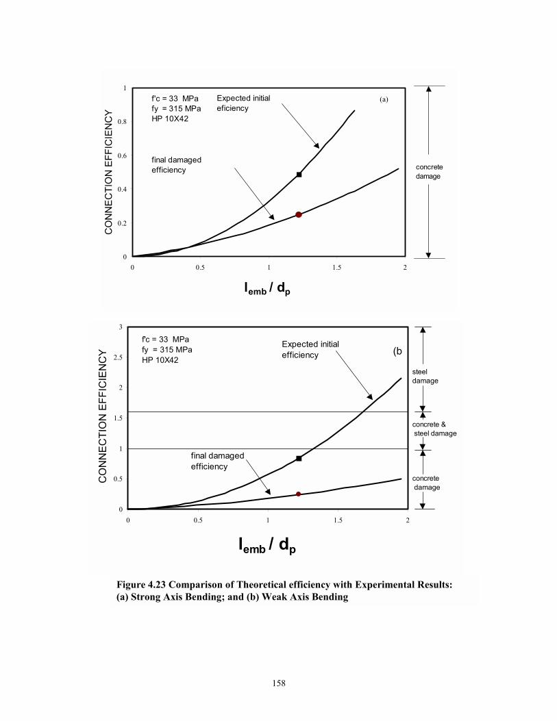
158
(b)
0
0.2
0.4
0.6
0.8
1
0 0.5 1 1.5 2
lemb / dp
CO
NN
ECTI
ON
EFF
ICIE
NC
Yf'c = 33 MPafy = 315 MPaHP 10X42
Expected initial eficiency
final damaged efficiency concrete
damage
(a)
0
0.5
1
1.5
2
2.5
3
0 0.5 1 1.5 2
lemb / dp
CO
NN
ECTI
ON
EFF
ICIE
NC
Y
final damaged efficiency
concrete damage
concrete & steel damage
steel damage
Expected initial efficiency
f'c = 33 MPafy = 315 MPaHP 10X42
Figure 4.23 Comparison of Theoretical efficiency with Experimental Results: (a) Strong Axis Bending; and (b) Weak Axis Bending
(b

159
value of cf = 0.85 'cf and substituting in equation (2.47) the expected initial efficiency
can be written as: 2
p
emb
f
p
y
'c
ES dl
td
ff
136.0
=ρ
The same approach used in deriving equation (4.5) was used to derive an equation for the
elastic cracking efficiency for weak axis bending:
2
f
emb
f
p
y
'c
Ew bl
td
ff
255.0
=ρ
Figure 4.23 plots the relationship between the normalized embedment depth and the
connection efficiency for both the strong and weak axis, using actual material and
dimensional properties. The figure shows that strong axis specimens with embedment
depth 300 mm would fail with damage mostly concentrated in concrete, which agrees
well with what happened for strong axis experiments. The figure also shows that elastic
efficiency for weak axis experiments are clod=se to unity which suggests initial damage
in the steel section and then with the onset of strain hardening in the steel section the
damage is expected to propagate into the concrete connection. This agrees well with what
happened for specimens W2 and PW. The theory , however, was conservative in
predicting the performance of specimen W1; this is presumed to be due to the in-situ
concrete strength being greater than indicated by the test cylinders.
4.5 CLOSURE
The present section outlined the results of a series of experiments to determine the
seismic vulnerability of existing pile-to-cap connections, characterized by small
embedment depth of the pile inside the cap beam (300mm). Based on the results
presented herein the following conclusions are drawn:
(4.6)
(4.5)

160
1. The experiments indicated that pile bent connections oriented along their strong axes
bending failed in a non-ductile manner within the concrete pile cap. Therefore, these
connections may be prone to damage under severe seismic loading, and hence, may
be in need of retrofit. 2. Specimen S1, tested without considering any axial load exhibited the lowest
performance among the pile bent specimens tested during the course of this
experimental program. 3. Pile bent connections oriented along their weak axes of bending exhibited superior
performance in terms of ductility and energy dissipation with respect to strong axis
connections. 4. Pile foundation connections failed in the concrete beam in a non-ductile brittle shear
mode. 5. The experiments demonstrated that predictions by both the cracked elastic and plastic
theories give an adequate representation of the joint strength range.
161
SECTION 5
EXPERIMENTAL RESULTS FOR RETROFITTED
PILE-TO-CAP CONNECTIONS
5.1 INTRODUCTION
Substructures consisting of either pile bents or pile foundations have been widely
used in the construction of highway bridges throughout the United States. But the
majority of these bridges were built two to three decades ago, when design of structures
for current high seismic loads was not required. Moreover, the experimental study
performed in this research on specimens simulating as-built substructures indicated that
the pile-to-pile cap connection, a connection primarily designed for vertical loading, is
very susceptible to damage from cyclic lateral loading. Therefore, in zones of moderate
to high seismicity it is prudent to perform any properly designed seismic strengthening
for this class of connection. It should be noted that a poorly conceived seismic retrofit
might result in more disastrous consequences than if the structure had been left alone.
Consequently, the primary focus of the retrofit scheme developed herein is to provide a
more ductile connection that can possess a large deformation capability permitting
dissipation of seismic energy in large earthquakes. Based on the experimental study on
pile bents to cap connections tested along the weak axis of the pile group, it is evident
that the pile-to-cap connections have an immense ductility capability, and thereby there is
no need for retrofit. If, however, biaxial loading is of concern, then retrofit should be
considered.
This section presents the experimental results of pile-to-cap connection that have
been retrofitted with the aim of strengthening the shear-critical connection and ensuring
plastification takes place only in the steel pile itself. This section first sets forth the
seismic retrofit strategy in accordance with the design concepts advocated in section 2
and then goes on to present and compare the test results.

162
5.2 CONSTRUCTION OF RETROFIT
5.2.1 Strong Axis Bending Pile Bents
The embedment depth of the retrofitted specimen was determined using equation
(2.79)
′
≥p
f
c
su
p
emb
dt
ff
5.3dl
for a 35 MPa concrete and 315 MPa steel and using the dimensions of the HP 10X42
steel pile section, the total embedment depth was determined as 625 mm. The original
specimen had an embedment depth = 300 mm. Therefore it was decided to use another
300 mm for the overlay depth.
The longitudinal reinforcement needed to close the anticipated gap between the
steel section and the concrete cap beam during cyclic loading is determined according to
equation (2.81):
2
yh
wPy
yh
Ps mm1397
413x85.054.10x246x2.315x6.0
ftdF6.0
fV
A ==φ
=φ
= .
∴ Use 4-25 mm diameter rebars (4#8, sA = 1963 2mm ).
The size and number of stirrups that resist the shear force was determined by
assuming 4 stirrups will resist the shear force. Therefore, according to equation (2.82)
kN02.611000x4
54.10x246x2.315x6.0x50.0n
V50.0V p
st ===
Substitute in equation (2.83)
(5.1)

163
(a)
Figure 5.1 Wire rope used for joint confinement Specimen # S3 (a) Specimen after completing the wire rope confinement, and (b) Specimen after installing the main cap reinforcement
(b)

164
23
y
stv mm148
41310x02.61
fV
A ===
∴ Use 12 mm diameter double leg stirrup ( sA = 226 2mm ).
To ensure joint confinement, additional transverse reinforcement (9.5 mm
diameter 1x7 galvanized wire rope) was added to the HP 10X42 steel pile along the
overlay length, with a spiral pitch of 50 mm. A photograph of specimen #3 with wire
rope wrapped in place is shown in figure 5.1 (a), and (b).
To facilitate the top-down pouring of concrete in an actual bridge, it was decided
to increase the width of the pile cap by 100 mm on each side. The first series of tests
showed that this increase in width would not enhance the cyclic performance of the
specimen. The additional width is required for practical purposes where the pile cap will
be in the inverted position in the actual bridge, and that extension of the width will
facilitate the concrete placing and compaction during the casting process in the field.
Additional reinforcement was provided in the form of # 4�s rebars (13-mm diameter)
every 150-mm for the longitudinal direction, for load distribution. Diagonal # 4 stirrups
were used to improve joint shear resistance. The rest of the stirrups were three sided (U
shaped) # 4's rebars. Figure 5.2 illustrates the reinforcing details for the pile bent retrofit
at the connections.
The stages of construction are summarized as follows:
I. The wire rope was provided first, and wrapped as one part around the three
specimens, finally it was fastened and attached to original concrete using a 13mm
galvanized wire rope clamp.
II. The 4#8 rebars were then installed in place followed by the No. 4 (13-mm
diameter) double leg stirrup as shown in figure 5.1b.
III. 7-16 mm diameter (7# 5) were provided as spacers along the two longitudinal
sides of the specimen. Two 16 mm one hole galvanized straps were used to hold
the spacer bars. The straps were attached to the sides of the original cap beam by
6 mm x 25mmx 9.5 mm sleeve concrete anchors drilled into the original concrete.
IV. The longitudinal # 4�s rebars were fastened to the spacer bars by tie wires.

165
2#8 #4@100
9.5 mm wire rope @50
2#4 diagonal
(a) Connections for specimens S1, and S2 (Elevation View)
(b) Connection for specimen S3
6#4
#4@200
Elevation Plan
Figure 5.2 Reinforcement Details For Connections ReS1, ReS2, and ReS3

166
Figure 5.3 Construction of Specimen Retrofit: Top Shows the Reinforcing Cage; Bottom Shows the Formwork Prior to Pouring the Concrete.

167
S ide
Vie
wEl
evat
ion
Pla n
Dim
ens i
ons
in m
m
# 4
Stirr
up @
100
2 #
8
# 4
@ 1
50
1/4
x 1
Anch
o r B
olt
# 5
Spac
er @
650
# 4
@ 2
00
9.5
mm
Wire
R
ope
@ 5
0
6 #
4
254
600
700
100
100
445 0
900
6 #
4#
4 @
200
2 #
8
9.5
mm
Wire
Rop
e @
50 #
4 St
i rrup
@ 1
00
3 5
Spac
er@
650
1/4
x 1
A nch
or B
olt
5 50
165 0
750
1500
854
6 #
49.
5 m
m W
ire R
ope
@ 5
0#
4 @
200 2 #
8 D
iago
nal
# 4
@ 1
502
# 8
# 4
Stirr
up @
100
Figu
re 5
.4 G
eom
etry
and
Rei
nfor
cem
ent F
or S
tron
g A
xis P
ile b
ent R
etro
fitte
d Sp
ecim
en

168
The U Shape stirrups were then attached to the longitudinal # 4�s rebars using tie wires.
V. Finally the formwork was installed and the concrete poured.
Photographs of the stages of the retrofit construction are shown in figure 5.3 (a) and (b).
The retrofitted specimen was constructed with ready-mix concrete. The ultimate compressive
strength of the concrete was determined from the results of three 150X300 mm cylinder test.
Results are shown in table 3.2. and (b). Figure 5.4 portrays different views for the retrofitted
specimen with typical dimensions.
5.2.2 Pile-Pile Cap Specimens
Due to the sudden brittle failure of the as built specimens, a 462 mm overlay length was
taken for the retrofitting of these specimens. This results in a full embedment depth of 762 mm.
According to equation (2.43), the nominal moment capacity of the connection can be expressed
as:
+
=
*emb
2embfc
j
Ll
6
lbfM
where, jM = the nominal moment capacity of concrete; cf = the concrete compressive stress at
the extreme fiber in the front face of the connection; embl = the total embedment depth of the
connection; *L = the distance from the point of application of the lateral load to the neutral axis
of the connection; and fb = the flange width of the steel pile section. If it is assumed according
to the retrofit strategy followed here that the plastic hinge would occur in the steel section.
Therefore, cf can be expressed as:
+= *
emb2embf
0Pc L
l6
lbM
f
(5.2)
(5.3)

169
in which 0pM = the plastic moment capacity of the steel section expressed as:
py00p ZfM φ=
Substituting the new value for embedment depth in equation (5.3) therfore:
+= *
emb2embf
0Pc L
l6
lbM
f = MPa3.1210677626
)762(x256791000x315x1.1
2 =
+
this value ensures that the stresses in the concrete along the embedment depth would be within
the elastic range.
The longitudinal reinforcement required to prevent concrete spalling at the pile cap edges
under cyclic loading is determined using equation (2.85).
2
embyh
psus mm1777
762x414791000x450x5.1
lfZf5.1
A === , assume 4 bars per pile bard = 24 mm.
Additional transverse reinforcement in the form of 9.5 mm diameter 1x7 galvanized wire
rope was added to provide confinement for concrete along the overlay depth within the flanges
of the pile (see figure 5.5).
Keeping in mind that pile cap foundations are usually constructed below the ground level,
and during the retrofit of these foundations, soil will be excavated to the level of the overlay
depth. Under these circumstances and to facilitate the concrete pouring and compaction, 300mm
was added to the pile cap width at the edges.
(5.4)

170
DIM
ENS I
ON
S IN
mm
9.5
mm
wire
rope
@5 0
Elev
atio
n
Plan
Sid e
Vie
w
Figu
re 5
.5 G
eom
etry
and
Rei
nfor
cem
ent F
or P
ile F
ound
atio
n R
etro
fit S
peci
men

171
(a)
(b)
Figure 5.6 Retrofit Construction of Pile Foundation Specimen, (a) WireRope set in place, and (b) Specimen after The Reinforcement wasAccomplished

172
The construction of the retrofit in the lab was carried out in three steps,
1. The wire rope was wrapped around the two specimens then fastened and attached to original
concrete using a 13mm galvanized wire rope clamp.
2. The main longitudinal L shaped 24mm reinforcement was set in place and fastened together.
3. Additional longitudinal reinforcement consisting of 13 mm rebars at 150 mm was added to
complete the reinforcing cage.
4. Finally the construction of the retrofit was concluded by setting the formwork in place and
placing the concrete.
Photographs of the steps of the retrofit construction are shown in figure 5.6.
5.3 SCOPE OF EXPERIMENTAL PROGRAM
The experimental program for testing the retrofitted specimens was similar to the one
used for as-built connections described previously in Section 4. For consistency, the same
loading procedures were employed. Therefore, the specimens were tested in displacement
control under incremental cyclic loading. Two cycles of drift at levels of %5.0± , %1± ,
%2± , %3± , %4± , %5± and %6± were applied. The quasi- statically displacement function
was sinusoidal with a one-minute period per cycle. Table 6.1 summarizes the axial loads and
drift information for each specimen tested in the retrofit study. During the load simulation for
specimens ReS2, and ReS3 the vertical load was mistakenly underestimated. This resulted in the
values shown in the table for the axial loads. These values were slightly less than those used for
the as-built specimens. However, this did not affect the potential performance of the specimens,
because it was observed during the first series of experiments for the as-built specimens, that
specimens ReS2 and ReS3 performed somewhat better than specimen RES1, tested without any
axial load. Consequently, testing specimens ReS2 and ReS3 in the second series of experiments
with a reduced axial load would ascertain the retrofit methodology developed in this retrofit
study.

173
Table 5.1 Test Program for Retrofitted Specimens
Spec.
ID
Gravity
Load
(kN)
Lateral
Actuator
Angle θ
Vertical Axial Load
Control (kN)
Total Axial
Load (kN)
Max.
Drift
No. of
Cycles at
Max. Drift
ReS1 0 0 0 0 5% 29
ReS2 150 0 150 150 6% 15
ReS3 120 24 120+1.43 daP 120+2.01V 5% 3
RePS 135 44 135+0.22 daP 135+1.27V 7% 0.5
RePW 135 44 135+0.22 daP 135+1.27V 5% 10
S = Strong Axis Bending W = Weak Axis Bending PS = Piles, Strong Axis PW = Piles, Weak Axis V = daP cos θ

174
5.4 GENERAL OBSERVATIONS
All the specimens were subjected to quasi-static applied drift up to failure. Pile bent
specimens possessed significant inelastic behavior beyond 2% drift. Pile foundation specimens
exhibited inelastic performance beyond 0.5% drift. This was characterized by flaking of
whitewash on both sides of the pile flanges.
A common form of failure mode was observed in specimens ReS1, and ReS2, where
fracture occurred in the flange (at 5% and 6% drift), that was subjected to compression during
joint closure (actuator pushing). The first cracks appeared at the flange, 120 mm above the
retrofitted concrete cap surface. The flaw then propagated horizontally with additional drift to
include the pile web. In the case of specimen ReS2, the flaw also propagated vertically in the
flange on both sides of the web. This failure mode was accompanied with local buckling of the
pile flanges in the hinge zone.
No noticeable cracks occurred in the reinforced concrete pile cap, except some minor
cover spalling observed in the immediate vicinity of the pile web. It was also observed, that the
gap which usually formed between the face of the steel flanges and the adjacent concrete, in the
first series of tests for specimens ReS1, and ReS2, before retrofitting the cap beam, did not occur
during the course of the second series of tests in specimens ReS1 and Res2. This corroborates the
retrofit strategy proposed here.
It was decided to stop the test for specimens ReS3 at 3% drift before it reached failure
due to out of plane motion of the pile at that drift.
During testing specimen RePS, one of the bolts connecting the actuator to the specimen
was fractured. As a result , the experimental setup was dismantled and the test was stopped at the
beginning of the 7% drift. The specimen, however, experienced severe local buckling without
being fractured.
5.5 FORCE DEFORMATION BEHAVIOR
5.5.1 Specimen ReS1
This specimen was tested without any axial load with two reversed cycles at drift
amplitude of ± 0.5%, ± 1%, ± 2%, ± 3%, ± 4%, and concluded with 26 cycles at ± 5%. The
complete hysteretic response of the specimen is shown in figure 5.7 . Yielding of the pile section

175
first occurred just prior to the 2% drift level, characterized by some diagonal striations on the
white washed flanges. Local buckling was initiated at the second cycle of 3% drift and continued
to grow as the drift amplitude increased. Strain hardening was observed on the first cycle at 3%
drift was attained. Beyond the 4% drift level, strength degradation of the steel material occurred
as a result of the local buckling.
The specimen was exposed to a continued cycles of constant amplitude testing at 5%
drift, through which strength degradation of the specimen continued. Finally on the th26 cycle,
a visible horizontal fatigue crack was observed at the flange subjected to compression when the
lateral actuator is pushing. The flaw growth continued during the last three cycles and
propagated horizontally to include part of the HP10X42 steel section web. Based on the crack
initiation, and crack growth mechanism, it is evident that the failure of that specimen was due to
low cycle fatigue. Photographs portraying such failure are shown in figure 5.8(a), (b).
5.5.2 Specimen ReS2
Specimen ReS2 was tested under a constant axial load of 150 kN with two reversed
cycles at drift amplitude of ± 0.5%, ± 1%, ± 2%, ± 3%, ± 4%, ± 5% and concluded with 15
cycles at ± 6%. Figure 5.9 presents the force-deformation results.
This Specimen exhibited inelastic behavior prior to 2% drift and experienced work
hardening in the pile steel material through both the 3% drift and the 4% drift cycles. Local
buckling of the steel pile flanges started to occur, along a 250mm distance above the cap beam
concrete surface, during the second cycle at 4% drift. Strength degradation of the steel pile
followed and was observable at the beginning of the 5% drift.
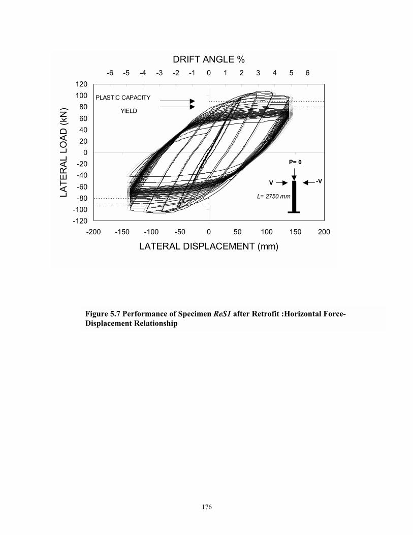
176
Figure 5.7 Performance of Specimen ReS1 after Retrofit :Horizontal Force-Displacement Relationship
-120-100
-80-60-40-20
020406080
100120
-200 -150 -100 -50 0 50 100 150 200
LATERAL DISPLACEMENT (mm)
LATE
RAL
LO
AD (k
N)
-7 -6 -5 -4 -3 -2 -1 0 1 2 3 4 5 6 7
DRIFT ANGLE %
PLASTIC CAPACITY
YIELD
V -V
P= 0
L= 2750 mm

177
Figure 5.8 Specimen ReS1 after Test. Top Photograph Shows aGeneral Side View, Bottom Photograph Shows a Close-up Viewof the Flange Buckling

178
It was decided to perform a constant cyclic high amplitude test phase at the 6% drift level up to
the fatigue failure of the specimen. A horizontal crack occurred at the compression flange after
the 12th cycle was completed. The flaw continued to grow, propagating vertically both sides of
the flange as well as horizontally in the web and fracture of the specimen was visible at the end
of the 15th cycle. At that point the test was stopped. Photographs illustrating the fracture of
specimen ReS2 due to low cyclic fatigue are shown in Figure 5.10a and 5.10b.
5.5.3 Specimen ReS3
Specimen ReS3 was tested under variable axial load with two reversed cycles at each
drift amplitude of ± 0.5%, ± 1%, ± 2%, ± 3%, ± 4% concluding with 3 cycles at ± 5%. This
specimen also satisfied the main objective of the conceptual elastic cap/elasto-plastic pile retrofit
strategy proposed in this study.
The specimen behaved in an elastic manner prior to 2% drift. Yielding of the flanges in
an area 250 mm above the added concrete surface was noticed through both the 2% and the 3%
drifts and diagonal yield lines were visible on the whitewashed flanges. Strain hardening of the
steel material also occurred during both the 2% and 3% drifts. Local buckling was initiated
during the second cycle at 3% drift. This local buckling became more pronounced during the 4%
drift and characterized by observable strength degradation in force displacement loops (see
figure 5.11). Due to shortcomings of the test setup, the test of pile specimen ReS3 was not
continued to reach the failure of the steel. Figure 5.12 plots the theoretical and experimental
lateral load-axial load interaction diagrams for this specimen. The maximum tension uplift ( 296
kN) occurred during the pull of the second cycle at 4% drift. The maximum lateral force
associated with this tension force was 117 kN. The specimen exhibited an average maximum
overstrength factor of 1.17. A photograph of this specimen after the completion of testing is
shown in figure 5.13.

179
Figure 5.9 Performance of Specimen ReS2 after Retrofit:Horizontal Force-Displacement Relationship
-120
-90
-60
-30
0
30
60
90
120
-200 -150 -100 -50 0 50 100 150 200
LATERAL DISPLACEMENT (mm)
LATE
RA
L LO
AD
(kN
)-7 -6 -5 -4 -3 -2 -1 0 1 2 3 4 5 6 7
DRIFT ANGLE %
Plastic StrengthPile Yield
P=150 kN
V -V
L=2750 mm

180
Figure 5.10 Specimen ReS2 after Testing. Top Shows a Side ViewIncluding the Location of the Fatigue Crack. The LowerPhotograph Shows an End View of the Specimen
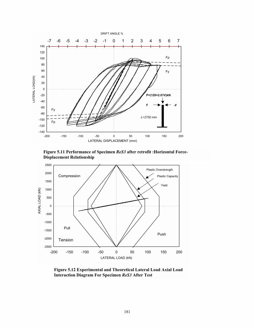
181
-2500
-2000
-1500
-1000
-500
0
500
1000
1500
2000
2500
-200 -150 -100 -50 0 50 100 150 200LATERAL LOAD (kN)
AXIA
L LO
AD (k
N)
Compression
TensionPush
Pull
Plastic Capacity
Yield
Plastic Overstrength
-7 -6 -5 -4 -3 -2 -1 0 1 2 3 4 5 6 7
-140
-120
-100
-80
-60
-40
-20
0
20
40
60
80
100
120
140
-200 -150 -100 -50 0 50 100 150 200LATERAL DISPLACEMENT (mm)
LATE
RAL
LO
AD(k
N)
DRIFT ANGLE %
F -F
P=(120+2.01V)kN
L=2750 mm
Fp
Fp
Fy
Fy
Figure 5.11 Performance of Specimen ReS3 after retrofit :Horizontal Force-Displacement Relationship
Figure 5.12 Experimental and Theoretical Lateral Load Axial Load Interaction Diagram For Specimen ReS3 After Test

182
Figure 5.13 Specimens ReS3 after Testing

183
5.5.4 Specimen RePW
Specimen RePW was tested under variable axial load with two reversed cycles at drift
amplitude of ± 0.25%, ± 0.5%, ± 1%, ± 2%, ± 3%, ± 4% concluding with 12 cycles at ± 5%.
The specimen was tested up to 5% drift without any significant damage in the concrete cap
beam. This behavior also validated the retrofit strategy proposed in this research. One should
keep in mind that this specimen exhibited a brittle shear failure in the cap beam prior to
retrofitting.
The overall performance of the connection was governed by the ductile behavior of the
steel pile. The specimen behaved in an elastic manner up to 0.5% drift. Inelastic action on the
section started to occur beyond this drift level. However, it was more pronounced during the
push of the first cycle at 2% drift and continued through the 3% cycle. The diagonal striations on
the white washed flanges extended to 200mm distance above the concrete beam surface during
the 3% drift and accompanied by a noticeable strain hardening of the steel material in the force-
displacement loops (see figure 5.14).
Local buckling was initiated during the second cycle at 4% drift and exerted some
strength degradation. Local buckling of both flanges continued to grow with the proceeding of
loading at the first two cycles at 5% drift.
Ten more cycles were conducted at 5% drift, strength degradation of the steel material
was more pronounced through these cycles. The test stopped after the Specimen completed 12
cycles at 5% drift. A photograph of the specimen after the test was completed is shown in figure
5.16.
Figure 5.15 plots the theoretical as well as experimental lateral load-axial load interaction
diagram for this specimen. The maximum tension uplift (164 kN) occurred during the pull of the
first cycle at 4% drift. The maximum lateral force associated with this tension force was 236 kN.
This specimen exhibited an average maximum overstrength factor of 1.32.

184
-2500
-2000
-1500
-1000
-500
0
500
1000
1500
2000
2500
-300 -200 -100 0 100 200 300LATERAL LOAD (kN)
AXIA
L LO
AD (k
N)
Overstrength Capacity
Plastic Capacity
Yield
Tension
PushPull
Compression
Figure 5.15 Experimental and Theoretical Lateral Load Axial Load Interaction Diagram For Specimen REPW After Retrofit
-7 -6 -5 -4 -3 -2 -1 0 1 2 3 4 5 6 7
-300
-200
-100
0
100
200
300
-50 -30 -10 10 30 50
LATERAL DISPLACEMENT (mm)
LATE
RAL
LO
AD (k
N)
DRIFT ANGLE %
Fp
Fy
Fy
Fp
F -F
L=685 mm
P=(135+1.27F)kN
Figure 5.14 Performance of Specimen RePW after retrofit : Horizontal Force-Displacement Relationship

185
Figure 5.16 Photograph of Specimen RePW after Testing

186
5.5.5 Specimen RePS:
Specimen RePS was tested under variable axial load with two reversed cycles at each
drift amplitude of ± 0.25%, ± 0.5%, ± 1%, ± 2%, ± 3%, ± 4% , ± 5% concluding with one
cycle at ± 6% and another half cycle at +7%. This specimen showed a ductile behavior in the
steel pile with few insignificant cracks in the concrete beam cover in a small region surrounding
the steel pile.
Due to shortcoming of the lateral actuator, the specimen did not attain the required
displacement during the push of first cycle at 2% drift. This displacement, however was attained
during the pull of this cycle. Another half cycle was tried manually at the same drift, then the
experiment stopped temporarily to replace the malfunctioning lateral actuator with another
actuator with the same specifications.
Yielding of the steel section of this specimen occurred prior to 1% drift level. The
inelastic behavior of the pile was pronounced during the 2% drift. This was characterized by
diagonal striations in both the white washed flanges and the web along a 125 mm distance above
the concrete cap beam surface. These striations extended to a distance of 200 mm above the
concrete surface during the first cycle at 3% drift with strain hardening of the steel material being
noticeable in the force-displacement loops.
Local buckling started to occur at the first cycle of the 3% drift, but it was very
pronounced, along a distance of 200mm, on the compressed flange, during the push of the second
cycle at this drift. It was noticed that this local buckling did not happen on the other flange
subjected to compression during the pull. This phenomenon was noticed also on the force-
displacement plot (figure 5.17) where the softening happened in the flange subjected to
compression in the push direction at the end of the 3% drift, while the flange on the other side
was still in the strain hardening phase. This phenomenon continued through the two cycles at 4%
drift.

187
-2500
-2000
-1500
-1000
-500
0
500
1000
1500
2000
2500
-800 -600 -400 -200 0 200 400 600 800
LATERAL LOAD(kN)
AXIA
L LO
AD (k
N)
Compression
Tension
Plastic Overstrength
Plastic Capacity
Yield
pushPull
Figure 5.18 Experimental and Theoretical Lateral Load Axial Load Interaction Diagram For Specimen RePS After Retrofit
-9 -8 -7 -6 -5 -4 -3 -2 -1 0 1 2 3 4 5 6 7 8 9
-600
-400
-200
0
200
400
600
-60 -40 -20 0 20 40 60
LATERAL DISPLACEMENT (mm)
LATE
RAL
LO
AD (k
N)
DRIFT ANGLE %
Fp
Fp
Fy
Fy
F -F
L= 685 mm
P= (135+1.27F) kN
Figure 5.17 Performance of Specimen RePS after retrofit: Horizontal Force-Displacement Relationship

188
One of the four anchor bolts attaching the lateral actuator to the specimen at the bearing
level yielded during the pull of the second cycle at 5% drift. The test stopped temporarily and
this bolt was replaced. One cycle at 6% drift was carried out, however, two other anchor bolts
attaching the lateral actuator to the specimen fractured suddenly by the end of this cycle. The test
continued another half cycle at 7% drift and then stopped. The fracture of these bolts occurred as
a result of their low cyclic fatigue because at the point of fracture, the steel pile was in the
strength degradation phase and these bolts have already sustained higher forces during the strain
hardening of the specimen. Photographs of the specimen after test are portrayed in figure 5.19.
Figure 5.18 shows the theoretical and experimental lateral load-axial load interaction
diagrams for specimen RePS. The maximum tension uplift (467kN) happened during the pull of
the second cycle at 4% drift. The maximum lateral force associated with this tension force was
482kN. The average maximum overstrength factor of this specimen is 1.18.
5.6 CLOSURE
The present section outlined the steps involved in the construction of the retrofit of the
pile bents and the pile foundation specimens. The results of a series of experiments to determine
the performance of the retrofitted specimens were then presented. Based on the results presented
in this section the following conclusions are drawn:
(i) Compared to the as-built case, specimen ReS1 exhibited superior energy absorption and
stable hysteretic response loops. This specimen exhibited two cycles, at 5% drift, with
non ductile failure at the concrete cap beam, under same loading conditions, before it was
retrofitted.
(ii) In the first series of tests for the as-built specimens, the presence of the axial load
improved the hysteretic response of specimen S2 when compared to S1. However,

189
Figure 5.19 Photographs of Specimen RePS after the Test

190
this was not the same case for the retrofitted specimens, where the axial load had a minor
influence on the strength of the connection. This was evidenced by the similar hysteretic
respone behavior of specimens ReS1 and ReS2.
(iii) Based on the lateral force-displacement of the exterior pile bent specimen, before (S3)
and after (ReS3) retrofit, one can realize the effectiveness of the retrofit strategy proposed
in the present study. In the pre-retrofit test, the concrete cap beam sustained some limited
cracking damage. This was characterized by the pinching in the lateral force-
displacement loops. This pinching, however, did not occur for the retrofitted test
specimen indicating that the connection behavior was governed by the ductile
performance of the steel section with the joint remaining intact.
(iv) The experimental results presented in this section indicated that the retrofitted specimens
possessed a superior performance in terms of ductility with respect to the as-built
specimens. Therefore, it is considered that the conceptual elastic cap/elasto-plastic steel
pile retrofit strategy proposed in this study is validated.
(v) It should be emphasized that the retrofitted pile-to-cap connections investigated in the
present study were tested to high drift amplitudes ± 6%. In an actual earthquake, the
structure may not exhibit such drifts. Therefore plastic hinging may be anticipated. Local
buckling failure was attained in the experimental study as a result of low cycle fatigue
under lateral loading, which may not happen during an actual seismic event.

191
SECTION 6
MODELING OF THE EXPERIMENTAL RESULTS
6.1 INTRODUCTION
The purpose of this section is to validate the theories developed in sections 2 and 3 for
predicting the lateral force displacement relationship and ductility ratios for different pile-to-cap
connections tested in the present study. Moreover, a fatigue theory is developed that predict the
low cycle fatigue behavior of the specimens that failed in such failure mode. The predictive
results are compared with experimental observations.
6.2 STRENGTH DEGRADATION AND ENERGY ABSORPTION CHARACTERISTICS
OF BRIDGE PILED SUBSTRUCTURES
One useful way of assessing the seismic vulnerability of a structural system is through the
identification of its energy absorption characteristics. This can be achieved by determining the
cyclic energy absorption efficiency factor η and the effective viscous damping ratio, effξ of the
system. This empowers a comparison between the structural seismic capacity and the seismic
demand. As mentioned in section 3, the efficiency factor η compares the energy absorbed by the
structure to a 100% perfect elasto-plastic system. Therefore, this factor indicates the ability of the
structure to absorb energy at a given drift level. The effective damping ratio, related to the
structural efficiency factor through equation (3.25), is an important parameter in assessing the
structural seismic vulnerability.
6.2.1 Energy Absorption Characteristics of As-Built Structures
6.2.1.1 Pile Bents Strong Axes Bending
The equivalent damping ratio calculated by equation (3.23) is plotted with respect to the
displacement ductility factor for the specimens in figures 6.1(a),(b) and (c). The data for Pile

192
Figure 6.1 Energy Dissipation Characteristics of Pile Bents Tested Along its Strong Axes
0.00
0.05
0.10
0.15
0.20
0.25
0 1 2 3 4DISPLACEMENT DUCTILITY FACTOR
EQU
IVA
LEN
T D
AM
PIN
G R
ATI
O
Pile S2 Data
Theoreticalη = 0.47
(b) Pile Specimen S2
0.00
0.05
0.10
0.15
0.20
0.25
0 1 2 3 4DISPLACEMENT DUCTILITY FACTOR
EQU
IVA
LEN
T D
AM
PIN
G R
ATI
O
Pile S3 Data
Theoreticalη = 0.43
(c) Pile Specimen S3
0.00
0.05
0.10
0.15
0.20
0.25
0 1 2 3 4
DISPLACEMENT DUCTILITY FACTOR
EQU
IVA
LEN
T D
AM
PIN
G R
ATI
OPile S1 Data
Theoreticalη = 0.47
(a) Pile Specimen S1

193
Specimens S1 and S2, plotted in figure 6.1(a) and (b), is compared to the predicted behavior
calculated by equation (3.23) with η = 47 %. Similarly, the predicted behavior for Pile Specimen
S3 is plotted in figure 6.1(c) with η= 43 %.
6.2.1.2 Pile Bents Weak Axes Bending
Specimen W1 exhibited an extraordinary energy absorption capability. Therefore a 80%
average value for efficiency was taken for this specimen. Specimen W2 had a satisfactory
performance too. It exhibited local buckling in the flanges, at 6% drift, followed by the concrete
failure during the last six cycles at 7.5% drift. Therefore a value of 55 % efficiency was assigned
to this specimen. Both specimens performed better than specimens S2, and S3 tested under
similar conditions along the strong axis bending.
The efficiency values assigned for the two specimens were implemented in equation
(3.23) to predict the theoretical ductility-damping ratio relationship. These relationships are
plotted for the two specimens in figures 6.2a, and 6.2b. The experimental values for these
relationships were plotted in both figures as dashed lines. The figures indicate satisfactory
correlation between the theoretical and experimental relationships.
6.2.1.3 Pile Foundations Strong and Weak Axes Bending
Pile foundation specimens failed in a non-ductile brittle shear mode. Accordingly, one
can deduce that they exhibited inferior energy absorption capabilities with respect to pile bent
specimens. It is obvious from figure 4.17b that specimen PS had no post-yield stiffness, as the
force deformation loops had a descending envelope, because the specimen failed suddenly in the
concrete cap without exhibiting any ductility in the steel pile material. Specimen PW
experienced some ductility in the steel pile material prior to failure. Therefore the theoretical
ductility-damping ratio relationships are compared to the experimental values before connection
fails and after failure. η was taken as 0.40 for specimen PS and 0.48 for specimen PW before the
connection fails. Those values ,however, were reduced to 0.28 and 0.22 for the two specimens

194
Figure 6.2 Energy Dissipation Characteristics of Pile Bents Tested Along its Weak Axes
0
0.1
0.2
0.3
0.4
0 1 2 3 4
DISPLACEMENT DUCTILITY FACTOR
EQU
IVA
LEN
T D
AM
PIN
G R
ATI
O
Theoretical
Pile W1 Data
(a) Specimen W1 Interior Pile
η = 0.80
0
0.1
0.2
0.3
0.4
0 1 2 3 4 5DISPLACEMENT DUCTILITY FACTOR
EQU
IVA
LEN
T D
AM
PIN
G R
ATI
O
Theoretical
Pile W2
(b) Specimen W2 Exterior Pile
η = 0.55

195
Figure 6.3 Energy Dissipation Characteristics of Piled Foundations Tested Along its Strong and Weak Axes
0
0.05
0.1
0.15
0.2
0.25
0 1 2 3 4 5 6
DISPLACEMENT DUCTILITY FACTOR
EQU
IVA
LEN
T D
AM
PIN
GR
ATI
O
Before Connection Fails η= 0.48
(b) Specimen PW
After Connection Fails η= 0.22
0
0.05
0.1
0.15
0.2
0.25
0 1 2 3 4 5 6DISPLACEMENT DUCTILITY FACTOR
EQU
IVA
LEN
T D
AM
PIN
G
RA
TIO
(a) Specimen PS Before Connection Fails η=0.40
After Connection Fails η=0.28

196
after failure. The efficiency values assigned for the two specimens were implemented in equation
(3.23) to compare with the experimental values of the ductility-damping ratio relationships.
These relationships are plotted for both specimens in Figures 6.3a and 6.36b respectively.
Satisfactory convergence was achieved between the theoretical and experimental equivalent
damping ratios
6.2.2 ENERGY ABSORPTION CHARACTERISTICS OF RETROFITTED STRUCTURES
6.2.2.1 Pile Bent Specimens
These specimens exhibited good energy absorption capabilities. Consequently a value of
80% is assigned for specimen ReS1 and 65% for both ReS2 and ReS3. The equivalent damping
ratio calculated by equation (3.23) is plotted versus the displacement ductility factor for the
specimens in figures 6.4a,6.4b and 6.4c. The experimental data for these specimens are shown
in the figures too. Satisfactory agreement was achieved between the experimental and predicted
values.
6.2.2.2 Piled Foundation Specimens
Both specimens PW and PS possessed high energy absorption capabilities. A values of
η= 60% is assigned for both specimens. The equivalent damping ratio calculated using equation
(3.23) is plotted versus the displacement ductility factor for the specimens in figures 6.5a and
6.5b. The experimental values are plotted in the same figure. The figures indicate good
correlation between the theoretical and experimental relationships.

197
0
0.1
0.2
0.3
0.4
0 1 2 3 4Displacement Ductility factor
Equi
vqle
nt D
ampi
ng R
atio
TheoreticalPile ReS1 Data
η= 0.8
(a) Specimen ReS1
0
0.1
0.2
0.3
0.4
0 1 2 3 4Displacement Ductility factor
Equi
vqle
nt D
ampi
ng R
atio
TheoreticalPile ReS2 Data
η= 0.70
(b) Specimen ReS2
0
0.1
0.2
0.3
0.4
0 1 2 3 4
Displacement Ductility factor
Equi
vqle
nt D
ampi
ng R
atio
TheoreticalPile ReS3 Dataη= 0.65
(c) Specimen ReS3
Figure 6.4 Energy Dissipation Characteristics of Retrofitted Pile Bents

198
Figure 6.5 Energy Dissipation Characteristics of Retrofitted Piled Foundations
0
0.1
0.2
0.3
0.4
0 1 2 3 4 5 6 7
Displacement Ductility factor
Equi
vale
nt D
ampi
ng R
atio
TheoreticalPile RePS Data
η= 0.60
(a) Specimen RePS
0
0.1
0.2
0.3
0.4
0 1 2 3 4 5 6 7
Displacement Ductility factor
Equi
vqle
nt D
ampi
ng R
atio
TheoreticalPile RePW Data
η= 0.60
( b) Specimen RePW

199
6.3 PUSHOVER MODELING OF AS-BUILT CONNECTIONS
Figures 6.6 through 6.8 show the cyclic normalized lateral force-drift relationships for as-
built specimens. The theoretical monotonic pushover curves are also plotted in the same graphs with
the experimental results. The figures demonstrate satisfactory agreement between the theoretical
algorithm and the experimental results. The convergence in the case of strong axis experiments
was slightly higher than in the case of weak axis experiments. This can be attributed to the
extensive work hardening that the weak axis specimens exhibited during testing, which was not
captured by the theoretical monotonic force-displacement algorithm.
Expectedly, the theoretical monotonic relationship overestimated the experimental one in
the case of specimen PS (figure6.8a). This is attributed to the sudden brittle failure mode that
this specimen experienced at the beginning of the 2% drift without any pronounced inelastic
behavior in the steel.
6.4 PUSHOVER MODELING OF RETROFITTED CONNECTIONS
Figures 6.10 and 6.11 display the cyclic normalized lateral force-drift relationships for
the retrofitted specimens. The theoretical relationships are also displayed in the graphs with
experimental results. Again, one can observe satisfactory agreement between the theoretical
prediction and experimental relationships.
To demonstrate the significance of considering the effect of the embedment depth in the
analysis, figure 6.11 compares the experimental results to two theoretical cases for specimen
RS1. Case 1 considers the steel pile fully fixed in the concrete base, and case 2 accounts for the
embedment depth in the analysis. It is observed that ignoring the embedment depth in the
analysis by considering the pile fixed to the cap beam does not represent the physical scenario.

200
Figure 6.6 Comparison of The Theoretical Approach with Experimental Results For Strong Axis As-built Pile Bent Specimens : (a) Specimen S1; (b) Specimen S2; and (c) Specimen S3
-1.5
-1
-0.5
0
0.5
1
1.5
-6 -4 -2 0 2 4 6
DRIFT ANGLE (%)
LOAD
RAT
IO (F
/Fp)
EXPERIMENTAL
THEORETICAL
(a)
-1.5
-1
-0.5
0
0.5
1
1.5
-8 -6 -4 -2 0 2 4 6 8
DRIFT ANGLE ( %)
LOAD
RAT
IO (F
/Fp)
EXPERIMENTAL
THEORETICAL
(b)
-1.5
-1
-0.5
0
0.5
1
1.5
-6 -4 -2 0 2 4 6
DRIFT ANGLE (%)
LOAD
RAT
IO (F
/Fp)
EXPERIMENTAL
THEORETICAL
(c)

201
Figure 6.7 Comparison of The Theoretical Approach with Experimental Results For Weak Axis As-built Pile Bent Specimens : (a) Specimen W1; (b) Specimen W2
-1.5
-1
-0.5
0
0.5
1
1.5
-8 -6 -4 -2 0 2 4 6 8
DRIFT ANGLE (%)
LOAD
RAT
IO (F
/FP)
EXPERIMENTALTHEORETICAL
(a)
-2
-1.5
-1
-0.5
0
0.5
1
1.5
2
-8 -6 -4 -2 0 2 4 6 8
DRIFT ANGLE %
LOAD
RAT
IO (F
/Fp)
EXPERIMENTALTHEORETICAL
(b)

202
Figure 6.8 Comparison of The Theoretical Approach with Experimental Results As-built Piled Foundation Specimens : (a) Specimen PS;(b) Specimen PW
-1.5
-1
-0.5
0
0.5
1
1.5
-6 -4 -2 0 2 4 6
DRIFT ANGLE %
LOAD
RAT
IO (F
/Fp)
EXPERIMENTALTHEORETICAL
-1.5
-1
-0.5
0
0.5
1
1.5
-6 -4 -2 0 2 4 6
DRIFT ANGLE %
LOAD
RAT
IO (F
/Fp)
EXPERIMENTAL
THEORETICAL

203
Figure 6.9 Comparison of The Theoretical Approach with Experimental Results For Strong Axis Retrofitted Pile Bent Specimens : (a) Specimen ReS1; (b) Specimen ReS2; and (c) Specimen ReS3
-1.5
-1
-0.5
0
0.5
1
1.5
-8 -6 -4 -2 0 2 4 6 8
DRIFT ANGLE %
LOAD
RAT
IO (F
/Fp)
EXPERIMENTAL
THEORETICAL
(a)
-1.5
-1
-0.5
0
0.5
1
1.5
-8 -6 -4 -2 0 2 4 6 8DRIFT ANGLE %
LOAD
RAT
IO (F
/Fp)
EXPERIMENTAL
THEORETICAL
(b)
-1.5
-1
-0.5
0
0.5
1
1.5
-8 -6 -4 -2 0 2 4 6 8DRIFT ANGLE %
LOAD
RAT
IO (F
/Fp)
EXPERIMENTALTHEORETICAL
(c)

204
Figure 6.10 Comparison of The Theoretical Approach with Experimental Results ForRetrofitted Piled Foundation Specimens : (a) Specimen RePS;(b) Specimen RePW
-1.5
-1
-0.5
0
0.5
1
1.5
-8 -6 -4 -2 0 2 4 6 8
DRIFT ANGLE %
LOAD
RAT
IO (F
/Fp)
EXPERIMENTALTHEORETICAL
-2.5
-2
-1.5
-1
-0.5
0
0.5
1
1.5
2
2.5
-8 -6 -4 -2 0 2 4 6 8
DRIFT ANGLE %
LOAD
RAT
IO (F
/Fp)
EXPERIMENTALTHEORETICAL
(b)

205
Figure 6.11 Illustrating the Importance of The Embedment Depth In Predicting The Theoretical Performance of Pile-to-Cap Connections
-120
-90
-60
-30
0
30
60
90
120
-150 -100 -50 0 50 100 150
DISPLACEMENT(mm)
LOAD
(kN
)
1 21 2

206
6.5 FATIGUE MODELING
The simplified procedure developed in section 2 to predict the seismic fatigue capacity of
the retrofitted connections is employed in this section to determine such capacity of the
specimens that exhibited a fatigue failure mode during the experiments (specimens ReS1, ReS2,
RePW).
6.5.1 Comparison of the Theoretical with Experimental Results
6.5.1.1 Determination of Equivalent Cycling
An appropriate method for cycle counting should be employed for the experimental
outcomes, in order to obtain results comparable with the theoretical model.
The equivalent number of cycles ( eqN ) to failure is commonly obtained using Miner's
linear damage accumulation rule (1945) which states that the damage accumulated up to the I-th
loading cycle is given by:
i321i N
1........N1
N1
N1D ++++=
where 1N , 2N , 3N ,�.., iN are the total numbers of cycle to failure if all cycles are at plastic
rotational amplitude piθ , thus it can be shown that:
∑−
θθ
=c
1
max
iieq nN
where in = the number of cycles at each drift iθ , maxθ = the maximum drift angle achieved, c =
exponential constant.
(6.1)
(6.2)
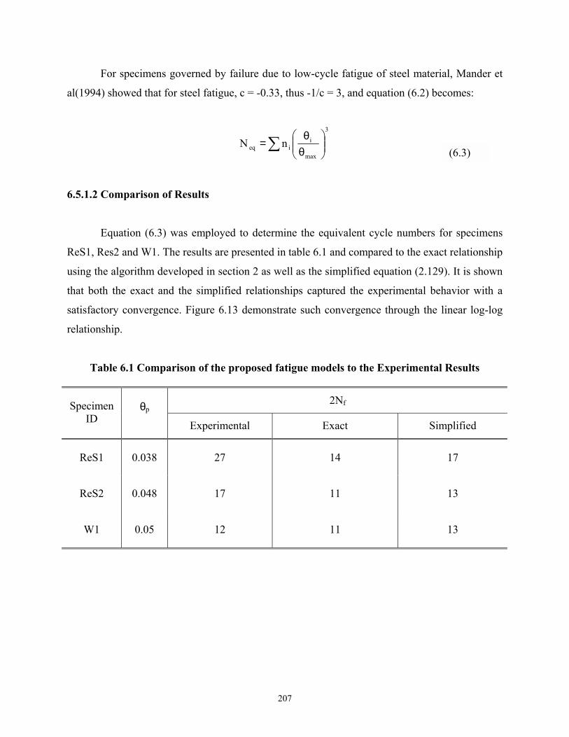
207
For specimens governed by failure due to low-cycle fatigue of steel material, Mander et
al(1994) showed that for steel fatigue, c = -0.33, thus -1/c = 3, and equation (6.2) becomes:
∑
θθ
=3
max
iieq nN
6.5.1.2 Comparison of Results
Equation (6.3) was employed to determine the equivalent cycle numbers for specimens
ReS1, Res2 and W1. The results are presented in table 6.1 and compared to the exact relationship
using the algorithm developed in section 2 as well as the simplified equation (2.129). It is shown
that both the exact and the simplified relationships captured the experimental behavior with a
satisfactory convergence. Figure 6.13 demonstrate such convergence through the linear log-log
relationship.
Table 6.1 Comparison of the proposed fatigue models to the Experimental Results
2Nf Specimen ID
θp
Experimental Exact Simplified
ReS1 0.038 27 14 17
ReS2 0.048 17 11 13
W1 0.05 12 11 13
(6.3)

208
Figure 6.12 Connection Plastic Rotation vs. Fatigue Life
0.001
0.1
1 10 1002Nf
θ p
ExactReS1ReS2W1Simplified

209
6.6 CLOSURE
The theory developed in section 2 for predicting the lateral force-displacement behavior
of steel piles to cap connections was validated in this section by comparing its outcomes to the
experimental results for all the specimens tested during the course of this study. Although some
differences are observed due to the effects of cyclic loading not counted for in the theoretical
model Satisfactory agreement was achieved between both cases.
The method outlined in section 3 for determining the equivalent damping ratio in terms of
the displacement ductility factor for the pile cap system was verified by experimental results and
hence values for the connection efficiency for different substructure conditions were evaluated.
These values can be employed for the evaluation of the seismic vulnerability of bridges
supported by such substructures.
Finally the fatigue life model, developed in section 2 was compared to the available
experimental results. Hence, this model can be used in future studies to predict the fatigue life of
these connections.


211
SECTION 7
CONCLUSIONS
7.1EXCUTIVE SUMMARY
The present study investigated the performance and retrofit of bridge pile-to-cap
connections that is representative of construction in the eastern and central US. Simplified
theoretical concepts were developed to predict the connection behavior under different
lateral and axial load patterns. Being compared to rigorous finite element analysis validated
these simplified limit theories. On the basis of these theories, design guidelines and retrofit
strategies for these connections were proposed.
A comprehensive experimental program was involved in the present study in order to
determine the seismic behavior of bridge pile-to-cap connections. Seven test specimens,
representing steel pile bents and pile foundations tested under different cyclic loading, were
investigated to identify their seismic vulnerability.
Based on the experimental study for the as-built specimens, a conceptual elastic
cap/elasto-plastic steel pile retrofit strategy was proposed in accordance with the design
concepts advocated in this study. In order to assess this retrofit strategy, another
experimental program consisted of testing five retrofitted test specimens was conducted .
An analytical approach for predicting the performance of these specimens under lateral
load was compared to the experimental results. Finally, a fatigue life model based on a
simplified approach was developed and compared to the available experimental results.

212
7.2 CONCLUDING REMARKS
Based on this experimental and analytical investigation reported herein, the following
specific conclusions can be drawn:
1. The experimental program for existing pile-to-cap connections, characterized by small
embedment depth of the pile inside the cap beam (300mm) indicated that pile and pile
bent connections oriented along their strong axes of bending failed in a non-ductile
manner within the concrete pile cap. Therefore these connections may be prone to
damage under severe earthquake loads, and hence, may be in need of retrofit.
2. Due to their lesser strength, pile bent connections oriented along their weak axes of
bending exhibited superior behavior with respect to strong axis connections, when tested
under the same loading conditions.
3. The experiments showed that the theoretical predictions by both the cracked elastic and
plastic theories developed in this study give an adequate representation of the joint
strength range.
4. Compared to the as-built specimens, the retrofitted specimens exhibited superior energy
absorption and stable hysteretic response loops.
5. On the basis of the performance of the specimens before and after retrofitting, it is
considered that the conceptual elastic cap/elasto-plastic steel pile retrofit strategy
proposed in this study is validated.
6. The analytical approach proposed in this study to simulate the monotonic force
displacement for various specimens tested under different loading conditions compared
favorably to the experimental back-bone curves for these specimens.
7. The fatigue life model proposed in the present study showed a satisfactory convergence
to a limited number of experimental results and hence. This can be used in future studies
to predict the fatigue-life of these connections.

213
7.3 RECOMMENDATIONS FOR FUTURE RESEARCH
1. In light of the information obtained from the comprehensive experimental program
implemented in this study for as-built and retrofitted piled substructures, an overall
seismic vulnerability study of bridges supported by steel piled substructures can be
performed. Through this study, the likelihood of structural damage due to various levels
of ground motions can be expressed by the aid of fragility curves.
2. The study needs to be extended to cover other types of piles such as timber piles, pipe
piles, and precast-concrete piles.
3. In the present study, the experimental setups were devised to investigate the performance
of individual pile bents. Future research may be extended to study the performance of
pile bent subassemblies consisting of more than one pile. Other issues including the
effect of bracing on the performance of timber pile bent subassemblies can be studied.
Furthermore, different bracing configurations can be employed to enhance the
performance of these subassemblies, and hence the need and/or effectiveness of
retrofitting strategies.


215
SECTION 8
REFERENCES
"ABAQUS 5.7 User's Manual", (1998), Hibbitt, Karlsson and Sorensen, Inc. ASCE-WRC (1971) "Plastic Design in Steel-A Guide and Commentary", Manual and Reports on Engineering Practice, No. 41, ASCE, New York, NY Broms, B.B. (1964a), " Lateral Resistances of Piles in Cohesive Soils", ASCE Journal of Soil Mechanics and Foundation Division, Vol. 90, No. SM2, pp. 27-63. Broms, B.B. (1964b), " Lateral Resistances of Piles in Cohesionless Soils", ASCE Journal of Soil Mechanics and Foundation Division, Vol. 90, No. SM3, pp. 123-156. Chai, YH and Hutchinson, TC (1999) " Flexural Strength and Ductility of Reinforced Concrete Bridge Piles", Report No. UCD-STR-99-2, Dept. of Civil & Environmental Engineering University of California Davis, CA Chang, G.A., Mander, J.B., (1994)" Seismic energy based fatigue damage analysis of bridge columns” Technical report (National Center for Earthquake Engineering Research); NCEER94-0013. Chopra, A.K., (1995), " Dynamics of Structures Theory and Applications to Earthquake Engineering", 1st Ed., Prentice-Hall, Inc. Cofin, L.F.Jr. (1954). " A study of the effects of cyclic thermal stresses on a ductile metal." Trans., American Society of Mechanical Engineers, New York, N.Y., 76, 931-950 Harries, K.A., Mitchell, D., Cook, W.D. and Redwood, R.G. (1993), " Seismic Response of Steel Beams Coupling Concrete Walls", Journal of Structural Engineering, Vol. 119, No. 12, Dec., pp. 3611-3629. Pam, J.H. and Park, R. (1990) " Flexural Strength and Ductility Analysis of Spirally Reinforced Prestressed Concrete Piles", PCI Journal. V 35 n 4 Jul-Aug 1990 p 64-83 Pam, J.H. Park, R. (1990)" Simulated Seismic Load Tests on Prestressed Concrete Piles and Pile-Pile Cap Connections", PCI Journal. V 35 n 6 Nov-Dec 1990 p 42-61 Japan National Earthquake Engineering Commission (1965)"Nigata Earthquake of July 1964", Proceedings of 3rd World Conference on Earthquake Engineering Kachadoorian, R.(1968)"Effects of The Earthquake of March 27, 1964, on The Alaska Highway System" Geological Survey Professional Paper 545-C

216
Mander, J.B., Dutta, A., and Goel, P. (1998), "Capacity design of bridge piers and the analysis of overstrength", Technical report (Multidisciplinary Center for Earthquake Engineering Research); MCEER-98-0003. Mander, J.B., Panthaki, F.D., and Kasalanti, A., (1994), " Low Cycle Fatigue Behavior of Reinforcing Steel", Journal of Materials in Civil Engineering, Vol. 6, No. 4, p. 453-468. Manson, S.S. (1953). " Behavior of materials under conditions of thermal stress." Heat Transfer Symp., University of Michigan Engineering Research Institute, Ann Arbor, Mich., 9-75 Marcakis, K. and Mitchell D. (1980), " Precast Concrete Connections with Embedded Steel Members", PCI Journal, Vol. 25, No. 4 July-August, pp. 88-116. Matlock, H., Stephen, H.C., and Larry, M.B (1978) "Simulation of Lateral Pile Behavior Under Earthquake Motion" Proceedings of the ASCE Geotechnical Engineering Division Specialty Conference, Pasadena, CA, pp.600-619 Mattock, A.H. and Gaafar, G.H. (1982), " Strength of Embedded Steel Sections as Brackets", ACI Journal March-April 1982 pp. 83-93 Miner, M.A., (1945), " Cumulative Damage in Fatigue", Journal of Applied Mechanics, September 1945, pp. A159-A164 Poulos, H.G. (1982) " Developments in the Analysis of Static and Cyclic Lateral Response of Piles" Proceedings of the Fourth International Conference on Numerical Methods in Geomechanics/Edmonton, Canada pp1117-11135 Priestley, M.J, Seible, F., and Calvi, G.M. (1997), Seismic Design and Retrofit of Bridges, 1st
Ed., John Wiley & Sons, Inc. Raths, C.H. (1974), " Embedded Structural Steel Connections", PCI Journal, Vol. 19, No. 3, May-June, PP. 104-112 Shaffer, M.D. and Williams, F.M. (1947), Research Report No.1- Investigation of The Strength of The Connection Between a Concrete Cap and the Embedded End of a Steel H-pile, State of Ohio Department of Highways, 79 pgs. Shama, A.A. (2000), "On the Seismic Analysis and Design of Pile-To-Cap Connections", Ph.D. Dissertation, State University of New York at Buffalo, Buffalo, NY. Steunenberg, M. Sexsmith, R G. Stiemer, S F. (1998) "Seismic Behavior of Steel Pile to Precast Concrete Cap Beam Connections", Journal of Bridge Engineering. V 3 n 4 Nov 1998. P 177-185 Xiao, Y, Mander J.B., Wu, H. and Martin, G (1999) " Experimental Study on Seismic Behavior of Bridge Pile-to-pile Cap Connections", 15th U.S.-Japan Bridge Engineering Workshop November 9 and 10, 1999 Tsukuba City, Japan.


University at Buffalo The State University of New York
ISSN 1520-295X