experimental evaluation of shear behavior of stone masonry
TRANSCRIPT
Materials 2021, 14, 2313. https://doi.org/10.3390/ma14092313 www.mdpi.com/journal/materials
Article
Experimental Evaluation of Shear Behavior of Stone
Masonry Wall
Maria Luisa Beconcini, Pietro Croce *, Paolo Formichi, Filippo Landi * and Benedetta Puccini
Department of Civil and Industrial Engineering, Structural Division, University of Pisa, 56122 Pisa, Italy;
[email protected] (M.L.B.); [email protected] (P.F.); [email protected] (B.P.)
* Correspondence: [email protected] (P.C.); [email protected] (F.L.);
Tel.: +39-335-534-5611 (P.C.); +39-339-198-1604 (F.L.)
Abstract: The evaluation of the shear behavior of masonry walls is a first fundamental step for the
assessment of existing masonry structures in seismic zones. However, due to the complexity of
modelling experimental behavior and the wide variety of masonry types characterizing historical
structures, the definition of masonry’s mechanical behavior is still a critical issue. Since the possibil-
ity to perform in situ tests is very limited and often conflicting with the needs of preservation, the
characterization of shear masonry behavior is generally based on reference values of mechanical
properties provided in modern structural codes for recurrent masonry categories. In the paper, a
combined test procedure for the experimental characterization of masonry mechanical parameters
and the assessment of the shear behavior of masonry walls is presented together with the experi-
mental results obtained on three stone masonry walls. The procedure consists of a combination of
three different in situ tests to be performed on the investigated wall. First, a single flat jack test is
executed to derive the normal compressive stress acting on the wall. Then a double flat jack test is
carried out to estimate the elastic modulus. Finally, the proposed shear test is performed to derive
the capacity curve and to estimate the shear modulus and the shear strength. The first results ob-
tained in the experimental campaign carried out by the authors confirm the capability of the pro-
posed methodology to assess the masonry mechanical parameters, reducing the uncertainty affect-
ing the definition of capacity curves of walls and consequently the evaluation of seismic vulnerabil-
ity of the investigated buildings.
Keywords: masonry; masonry mechanical parameters; flat jack test; shear test; shear behavior;
capacity curve; seismic vulnerability
1. Introduction
Masonry buildings are a large part of a built environment, especially in historical
towns. Since these structures were mostly built according to empirical rules and without
following specific seismic design provisions, they are often characterized by a high seis-
mic vulnerability. In addition, the need of preservation makes the assessment of their
structural performance a significant criterion for planning maintenance and strengthen-
ing interventions [1,2].
Understanding and modelling the mechanical behavior of masonry elements is a
long-standing challenge in civil engineering [3]. In fact, the characterization of mechanical
properties of masonry is certainly one of the most delicate issues in the process, especially
in the field of heritage structures, where modern studies suggest also to resort to advanced
probabilistic approaches [4].
The characterization of the shear behavior of each wall is the basis for a sound as-
sessment of the seismic vulnerability of a masonry building. As known, seismic perfor-
mance, which is commonly evaluated through nonlinear static analysis, is highly depend-
ent on assumptions related to the main mechanical parameters of the material: shear
Citation: Beconcini, M.L.; Croce, P.;
Formichi, P.; Landi, F.; Puccini, B.
Experimental Evaluation of Shear
Behavior of Stone Masonry Wall.
Materials 2021, 14, 2313. https://
doi.org/10.3390/ma14092313
Academic Editor: Marco Corradi
Received: 30 March 2021
Accepted: 27 April 2021
Published: 29 April 2021
Publisher’s Note: MDPI stays neu-
tral with regard to jurisdictional
claims in published maps and institu-
tional affiliations.
Copyright: © 2021 by the authors. Li-
censee MDPI, Basel, Switzerland.
This article is an open access article
distributed under the terms and con-
ditions of the Creative Commons At-
tribution (CC BY) license (http://crea-
tivecommons.org/licenses/by/4.0/).
Materials 2021, 14, 2313 2 of 19
modulus, �; elastic modulus, �; shear strength, ��; global stiffness; and displacement ca-
pacity. Sensitivity studies carried out by the authors [1,5,6] emphasized that the seismic
risk index ��, which summarizes the seismic performance of the structure, could signifi-
cantly vary depending on the assumptions about the shear behavior of masonry walls.
As confirmed by the available experimental results [7], the estimate of the shear mod-
ulus of the masonry is characterized by huge uncertainty. Actually, the shear modulus
and the effective stiffness of masonry walls not only are a function of the masonry type,
but significantly depend on the adopted test setup [8], which usually can include vertical
compression tests [9], diagonal compression tests [10], and shear compression tests [11].
Since global resistance, effective stiffness, and shear failure mechanisms of the wall de-
pend on compressive stresses, quality of mortar [8,12], and other influencing parameters,
the shear behavior of masonry walls has been deeply investigated [2,7,8,13–18] to deter-
mine the most relevant relationships.
It must be remarked that in situ test procedures usually consist of diagonal compres-
sion and shear compression tests performed on panels, suitably obtained by cutting the
walls, which are completely reconstructed after the test. Owing to the fact that this kind
of tests can be extremely invasive, the setup of new testing methodologies allowing suit-
ably fast but accurate estimation of masonry parameters is thus a priority, also in view of
the definition of the capacity curves of masonry walls [5].
In the framework of an important research project regarding the seismic assessment
of more than 80 school masonry buildings in Florence, a wide in situ experimental cam-
paign was carried out by the authors on different masonry typologies [2]. The experi-
mental results, compared with the ones derived adopting different test methods on simi-
lar masonry walls, allowed for identifying suitable modifications of the test arrangements.
In the paper, an innovative in situ shear test arrangement for masonry panels is illus-
trated, together with the first promising experimental results. The proposed test proce-
dure, which can be considered less invasive than the alternatives, is able to provide the
relevant parameters that are needed to model the shear behavior of walls (i.e., elastic mod-
ulus, �; shear modulus, �; and shear strength, ��) [1,2].
In the following sections, the current procedures for the mechanical characterization
of masonry walls are preliminarily recalled and commented. Then the proposed testing
methodology is presented, also referring to the experimental results.
Finally, the obtained results are critically discussed, highlighting the most significant
parameters, also considering their dependence on basic assumptions and the main fea-
tures of other commonly adopted shear models.
2. Mechanical Behavior of Masonry Walls
2.1. Masonry Categories
Masonry has been the main construction material for millennia. Since historic con-
structions, built by craftspeople, are not the result of industrial processes, they are char-
acterized by a large variety of masonry types.
The quality and mechanical properties of a given masonry type depend on many
factors, such as availability of the constituent materials, building importance, skills of
workmanship, local customs, and architectural canons, if any [2]. For that reason, the
properties of similar existing masonry can vary in a wide range.
Some preliminary guidance can be often found in modern structural codes, where
typical ranges of values for compressive resistance, ��; shear resistance, ��; elastic mod-
ulus, �; shear modulus, �; and specific weight, �, are given for recurrent masonry typol-
ogies. For example, the Italian Building Code provides information for eight recurrent
masonry typologies: irregular stone masonry, partially dressed stone masonry, well-
dressed stone masonry, irregular soft-stone masonry, squared soft-stone masonry,
squared hard-stone masonry, brickwork masonry with lime-based mortar, and hollow-
bricks masonry with cement mortar [19]. These ranges, summarized in Table 1, refer to
Materials 2021, 14, 2313 3 of 19
low-quality masonry, but they can be suitably adjusted and increased for masonry of im-
proved quality, depending on mortar strength, thickness of mortar joints, regularity of
courses, efficiency of transverse connections, and quality of inner core if any, as well as on
strengthening intervention, like grout injection and external concrete layers.
Anyhow, even if the masonry typology is well identified, subjective judgements can
notably influence the estimation of mechanical properties. In practical cases, a possible
solution could consist in supplementing the reference values of the mechanical properties,
pertaining to the identified masonry typology, with the results of limited semidestructive
or nondestructive in situ tests. A procedure for the identification of masonry classes and
their mechanical parameters is presented in [2], based on the analysis of available datasets
of test results, complemented with some additional information on masonry quality [18]
and in situ test results.
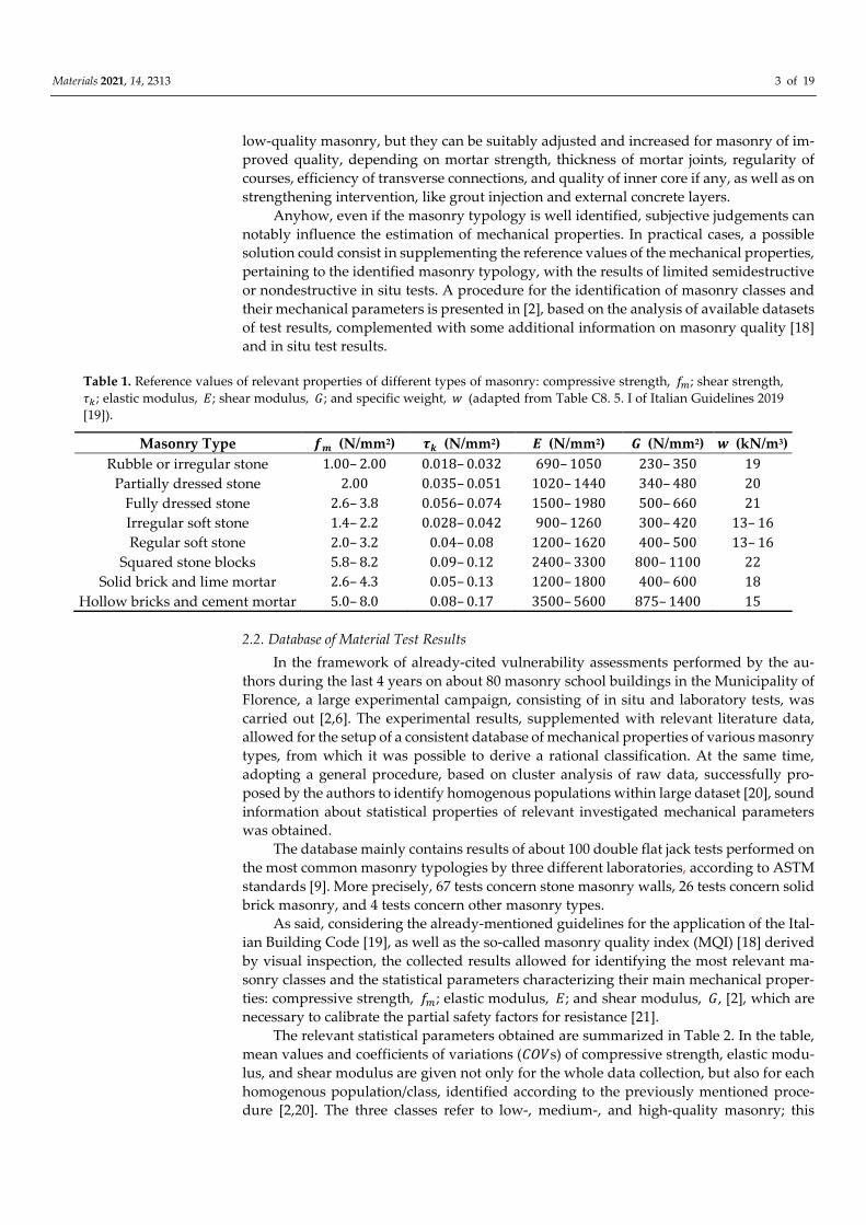
Table 1. Reference values of relevant properties of different types of masonry: compressive strength, ��; shear strength,
��; elastic modulus, �; shear modulus, �; and specific weight, � (adapted from Table C8. 5. I of Italian Guidelines 2019
[19]).
Masonry Type �� (N/mm2) �� (N/mm2) � (N/mm2) � (N/mm2) � (kN/m3)
Rubble or irregular stone 1.00– 2.00 0.018– 0.032 690– 1050 230– 350 19
Partially dressed stone 2.00 0.035– 0.051 1020– 1440 340– 480 20
Fully dressed stone 2.6– 3.8 0.056– 0.074 1500– 1980 500– 660 21
Irregular soft stone 1.4– 2.2 0.028– 0.042 900– 1260 300– 420 13– 16
Regular soft stone 2.0– 3.2 0.04– 0.08 1200– 1620 400– 500 13– 16
Squared stone blocks 5.8– 8.2 0.09– 0.12 2400– 3300 800– 1100 22
Solid brick and lime mortar 2.6– 4.3 0.05– 0.13 1200– 1800 400– 600 18
Hollow bricks and cement mortar 5.0– 8.0 0.08– 0.17 3500– 5600 875– 1400 15
2.2. Database of Material Test Results
In the framework of already-cited vulnerability assessments performed by the au-
thors during the last 4 years on about 80 masonry school buildings in the Municipality of
Florence, a large experimental campaign, consisting of in situ and laboratory tests, was
carried out [2,6]. The experimental results, supplemented with relevant literature data,
allowed for the setup of a consistent database of mechanical properties of various masonry
types, from which it was possible to derive a rational classification. At the same time,
adopting a general procedure, based on cluster analysis of raw data, successfully pro-
posed by the authors to identify homogenous populations within large dataset [20], sound
information about statistical properties of relevant investigated mechanical parameters
was obtained.
The database mainly contains results of about 100 double flat jack tests performed on
the most common masonry typologies by three different laboratories, according to ASTM
standards [9]. More precisely, 67 tests concern stone masonry walls, 26 tests concern solid
brick masonry, and 4 tests concern other masonry types.
As said, considering the already-mentioned guidelines for the application of the Ital-
ian Building Code [19], as well as the so-called masonry quality index (MQI) [18] derived
by visual inspection, the collected results allowed for identifying the most relevant ma-
sonry classes and the statistical parameters characterizing their main mechanical proper-
ties: compressive strength, ��; elastic modulus, �; and shear modulus, �, [2], which are
necessary to calibrate the partial safety factors for resistance [21].
The relevant statistical parameters obtained are summarized in Table 2. In the table,
mean values and coefficients of variations (���s) of compressive strength, elastic modu-
lus, and shear modulus are given not only for the whole data collection, but also for each
homogenous population/class, identified according to the previously mentioned proce-
dure [2,20]. The three classes refer to low-, medium-, and high-quality masonry; this
Materials 2021, 14, 2313 4 of 19
classification, simple and very effective from the engineering point of view, reflects the
results of the cluster analysis [2].
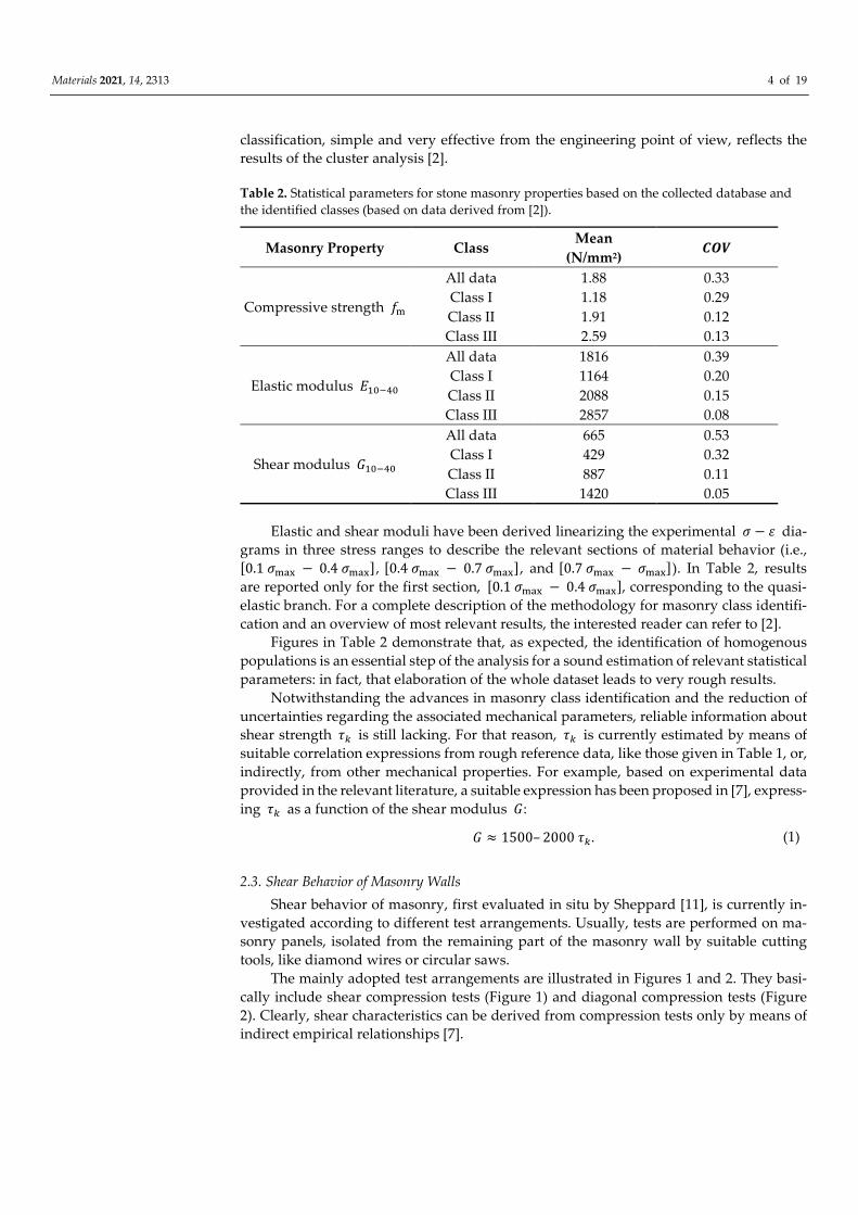
Table 2. Statistical parameters for stone masonry properties based on the collected database and
the identified classes (based on data derived from [2]).
Masonry Property Class Mean
(N/mm2) ���
Compressive strength ��
All data 1.88 0.33
Class I 1.18 0.29
Class II 1.91 0.12
Class III 2.59 0.13
Elastic modulus ������
All data 1816 0.39
Class I 1164 0.20
Class II 2088 0.15
Class III 2857 0.08
Shear modulus ������
All data 665 0.53
Class I 429 0.32
Class II 887 0.11
Class III 1420 0.05
Elastic and shear moduli have been derived linearizing the experimental � − � dia-
grams in three stress ranges to describe the relevant sections of material behavior (i.e.,
[0.1 ���� − 0.4 ����], [0.4 ���� − 0.7 ����], and [0.7 ���� − ����]). In Table 2, results
are reported only for the first section, [0.1 ���� − 0.4 ����], corresponding to the quasi-
elastic branch. For a complete description of the methodology for masonry class identifi-
cation and an overview of most relevant results, the interested reader can refer to [2].
Figures in Table 2 demonstrate that, as expected, the identification of homogenous
populations is an essential step of the analysis for a sound estimation of relevant statistical
parameters: in fact, that elaboration of the whole dataset leads to very rough results.
Notwithstanding the advances in masonry class identification and the reduction of
uncertainties regarding the associated mechanical parameters, reliable information about
shear strength �� is still lacking. For that reason, �� is currently estimated by means of
suitable correlation expressions from rough reference data, like those given in Table 1, or,
indirectly, from other mechanical properties. For example, based on experimental data
provided in the relevant literature, a suitable expression has been proposed in [7], express-
ing �� as a function of the shear modulus �:
� ≈ 1500– 2000 ��. (1)
2.3. Shear Behavior of Masonry Walls
Shear behavior of masonry, first evaluated in situ by Sheppard [11], is currently in-
vestigated according to different test arrangements. Usually, tests are performed on ma-
sonry panels, isolated from the remaining part of the masonry wall by suitable cutting
tools, like diamond wires or circular saws.
The mainly adopted test arrangements are illustrated in Figures 1 and 2. They basi-
cally include shear compression tests (Figure 1) and diagonal compression tests (Figure
2). Clearly, shear characteristics can be derived from compression tests only by means of
indirect empirical relationships [7].
Materials 2021, 14, 2313 5 of 19
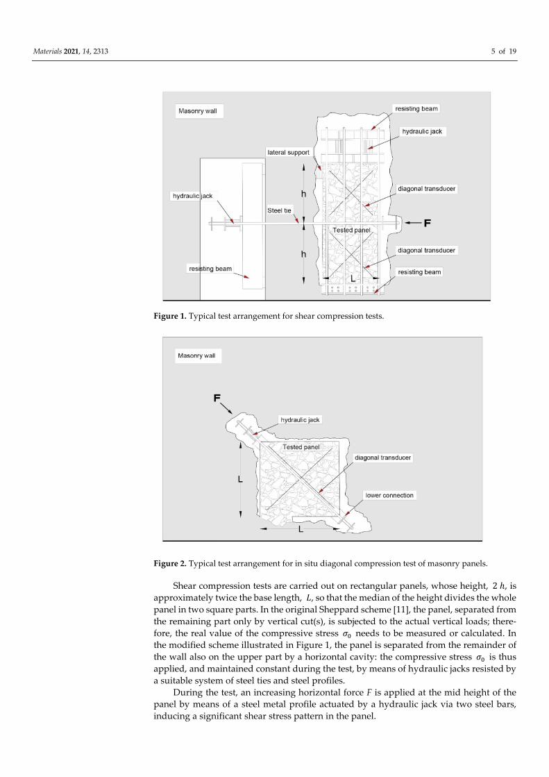
Figure 1. Typical test arrangement for shear compression tests.
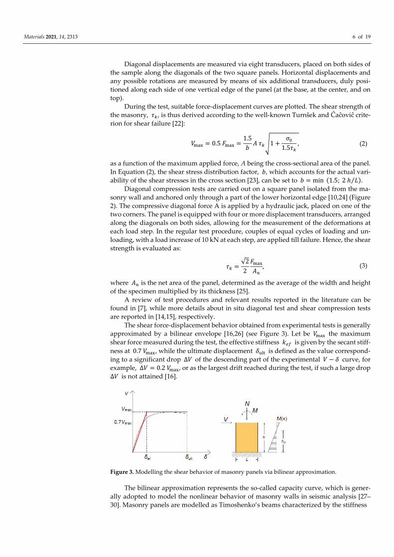
Figure 2. Typical test arrangement for in situ diagonal compression test of masonry panels.
Shear compression tests are carried out on rectangular panels, whose height, 2 ℎ, is
approximately twice the base length, �, so that the median of the height divides the whole
panel in two square parts. In the original Sheppard scheme [11], the panel, separated from
the remaining part only by vertical cut(s), is subjected to the actual vertical loads; there-
fore, the real value of the compressive stress �� needs to be measured or calculated. In
the modified scheme illustrated in Figure 1, the panel is separated from the remainder of
the wall also on the upper part by a horizontal cavity: the compressive stress �� is thus
applied, and maintained constant during the test, by means of hydraulic jacks resisted by
a suitable system of steel ties and steel profiles.
During the test, an increasing horizontal force F is applied at the mid height of the
panel by means of a steel metal profile actuated by a hydraulic jack via two steel bars,
inducing a significant shear stress pattern in the panel.
Materials 2021, 14, 2313 6 of 19
Diagonal displacements are measured via eight transducers, placed on both sides of
the sample along the diagonals of the two square panels. Horizontal displacements and
any possible rotations are measured by means of six additional transducers, duly posi-
tioned along each side of one vertical edge of the panel (at the base, at the center, and on
top).
During the test, suitable force-displacement curves are plotted. The shear strength of
the masonry, ��, is thus derived according to the well-known Turnšek and Ĉaĉoviĉ crite-
rion for shear failure [22]:
���� = 0.5 ���� =1.5
�� ���1 +
��
1.5��
, (2)
as a function of the maximum applied force, A being the cross-sectional area of the panel.
In Equation (2), the shear stress distribution factor, �, which accounts for the actual vari-
ability of the shear stresses in the cross section [23], can be set to � = min (1.5; 2 ℎ �⁄ ).
Diagonal compression tests are carried out on a square panel isolated from the ma-
sonry wall and anchored only through a part of the lower horizontal edge [10,24] (Figure
2). The compressive diagonal force A is applied by a hydraulic jack, placed on one of the
two corners. The panel is equipped with four or more displacement transducers, arranged
along the diagonals on both sides, allowing for the measurement of the deformations at
each load step. In the regular test procedure, couples of equal cycles of loading and un-
loading, with a load increase of 10 kN at each step, are applied till failure. Hence, the shear
strength is evaluated as:
�� =√2
2
����
��
, (3)
where �� is the net area of the panel, determined as the average of the width and height
of the specimen multiplied by its thickness [25].
A review of test procedures and relevant results reported in the literature can be
found in [7], while more details about in situ diagonal test and shear compression tests
are reported in [14,15], respectively.
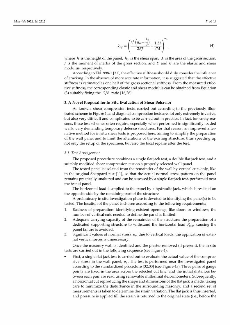
The shear force-displacement behavior obtained from experimental tests is generally
approximated by a bilinear envelope [16,26] (see Figure 3). Let be ���� the maximum
shear force measured during the test, the effective stiffness ��� is given by the secant stiff-
ness at 0.7 ����, while the ultimate displacement ���� is defined as the value correspond-
ing to a significant drop ∆� of the descending part of the experimental � − � curve, for
example, ∆� = 0.2 ����, or as the largest drift reached during the test, if such a large drop
∆� is not attained [16].
Figure 3. Modelling the shear behavior of masonry panels via bilinear approximation.
The bilinear approximation represents the so-called capacity curve, which is gener-
ally adopted to model the nonlinear behavior of masonry walls in seismic analysis [27–
30]. Masonry panels are modelled as Timoshenko’s beams characterized by the stiffness
Materials 2021, 14, 2313 7 of 19
��� = �ℎ� �ℎ� −
ℎ3
�
2��+
1.2ℎ
���
��
, (4)
where ℎ is the height of the panel, ℎ� is the shear span, � is the area of the gross section,
� is the moment of inertia of the gross section, and � and � are the elastic and shear
modulus, respectively.
According to EN1998-1 [31], the effective stiffness should duly consider the influence
of cracking. In the absence of more accurate information, it is suggested that the effective
stiffness is estimated as one half of the gross sectional stiffness. From the measured effec-
tive stiffness, the corresponding elastic and shear modulus can be obtained from Equation
(3) suitably fixing the �/� ratio [16,26].
3. A Novel Proposal for In Situ Evaluation of Shear Behavior
As known, shear compression tests, carried out according to the previously illus-
trated scheme in Figure 1, and diagonal compression tests are not only extremely invasive,
but also very difficult and complicated to be carried out in practice. In fact, for safety rea-
sons, these test schemes often require, especially when performed in significantly loaded
walls, very demanding temporary defense structures. For that reason, an improved alter-
native method for in situ shear tests is proposed here, aiming to simplify the preparation
of the wall panel and to limit the alterations of the existing structure, thus speeding up
not only the setup of the specimen, but also the local repairs after the test.
3.1. Test Arrangement
The proposed procedure combines a single flat jack test, a double flat jack test, and a
suitably modified shear compression test on a properly selected wall panel.
The tested panel is isolated from the remainder of the wall by vertical cuts only, like
in the original Sheppard test [11], so that the actual normal stress pattern on the panel
remains practically unaltered and can be assessed by a single flat jack test, performed near
the tested panel.
The horizontal load is applied to the panel by a hydraulic jack, which is resisted on
the opposite side by the remaining part of the structure.
A preliminary in situ investigation phase is devoted to identifying the panel(s) to be
tested. The location of the panel is chosen according to the following requirements:
1. Easiness of preparation: identifying existent openings, like doors or windows, the
number of vertical cuts needed to define the panel is limited.
2. Adequate carrying capacity of the remainder of the structure: the preparation of a
dedicated supporting structure to withstand the horizontal load ���� causing the
panel failure is avoided.
3. Significant values of normal stress �� due to vertical loads: the application of exter-
nal vertical forces is unnecessary.
Once the masonry wall is identified and the plaster removed (if present), the in situ
tests are carried out in the following sequence (see Figure 4):
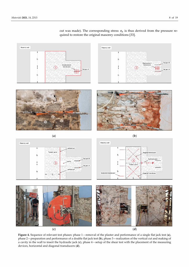
First, a single flat jack test is carried out to evaluate the actual value of the compres-
sive stress in the wall panel, ��. The test is performed near the investigated panel
according to the standardized procedure [32,33] (see Figure 4a). Three pairs of gauge
points are fixed in the area across the selected cut line, and the initial distances be-
tween each pair are read using removable millesimal deformometers. Subsequently,
a horizontal cut reproducing the shape and dimensions of the flat jack is made, taking
care to minimize the disturbance in the surrounding masonry, and a second set of
measurements is taken to determine the strain variation. The flat jack is thus inserted,
and pressure is applied till the strain is returned to the original state (i.e., before the
Materials 2021, 14, 2313 8 of 19
cut was made). The corresponding stress �� is thus derived from the pressure re-
quired to restore the original masonry conditions [33].
(a) (b)
(c) (d)
Figure 4. Sequence of relevant test phases: phase 1—removal of the plaster and performance of a single flat jack test (a),
phase 2—preparation and performance of a double flat jack test (b), phase 3—realization of the vertical cut and making of
a cavity in the wall to insert the hydraulic jack (c), phase 4—setup of the shear test with the placement of the measuring
devices, horizontal and diagonal transducers (d).
Materials 2021, 14, 2313 9 of 19
It is important to recall here that even if a single flat jack test represents a common
and powerful tool for the evaluation of the acting stress [34], a careful interpretation
of results is required. In fact, conflicting information can be obtained by the different
deformometers due to the local presence of inelastic deformations, which is caused
by the nonuniform stress distribution after the horizontal cut. An accurate visual in-
spection of the investigated area around the cut is thus an essential step for a correct
understanding of the response of the measuring devices, and a correction may be
needed to determine the stress �� as described in [35]. Moreover, since the location
of the test is close to the investigated panel but still not coincident (see Figure 4), the
resulting stress �� should also be checked and compared with the vertical load com-
puted by load analysis considering the actual loads on the structure.
After that, a second horizontal cut is made, vertically spaced about 500 mm from the
previous one, and a double flat jack test [9] (see Figure 4b) is carried out to determine
the elastic modulus, �, and the compressive strength, ��. Once the second flat jack
is inserted, four pairs of measurement bases, three orthogonal to the cuts and one
parallel to them, are installed between the two jacks, and the initial base lengths are
measured. The pressure is gradually increased, recording the strain variations for
each pressure increment. The test is stopped when the ratio between the increase of
jack pressure and the strain increment rapidly drops and the first cracks occur in the
masonry. From the experimental � − � diagram recorded, the elastic modulus, �, in
different behavioral conditions can be derived, as a function of the load level. As al-
ready mentioned in Section 2, three different stress ranges are considered:
[0.1 ���� − 0.4 ����], [0.4 ���� − 0.7 ����], and [0.7 ���� − ����], representing the
quasi-elastic, the cracked, and the plastic sections of the diagram, respectively, so that
the pertinent secant elastic moduli can be derived.
Finally, the shear compression test is performed, as described below (see also Figures
4c,d and 5), to evaluate the shear behavior and to identify the shear strength, ��, and
the shear modulus, �, of the masonry.
The sequence of the relevant phases for the preparation of the tests and their perfor-
mance is summarized in Figure 4: removal of the plaster and performance of a single flat
jack test (phase 1), preparation and performance of a double flat jack test (phase 2), reali-
zation of the vertical cut and making of a cavity in the wall to insert the hydraulic jack
(phase 3), and setup of the shear test with the placement of the measuring devices, hori-
zontal and diagonal transducers (phase 4).
As anticipated, the test setup is conceived in such a way to simplify the preparation
of the wall panel and to facilitate the analysis and interpretation of the behavior of the
wall panel itself. To isolate a masonry panel of adequate length, a 1.6– 1.8 m long vertical
cut is made in the wall at 0.8– 0.9 m distance from an opening in such a way to obtain a
panel with a height/length ratio of about 2 (see Figure 5). Evidently, the proposed scheme
is much more general; in fact, when openings are not present, it remains feasible, although
a little more complex, since it requires an additional vertical cut.
As already remarked, in that way the test procedures are simplified and the pertur-
bations of the existing stress pattern in the panel are minimized. In fact, since the wall
panel is subjected to an almost constant compressive stress �� caused by the existing ver-
tical loads acting on the structure, the system of steel plates, rods, and hydraulic jacks
required in the classical shear compression test scheme (Figure 1) [11] for the introduction
of compressive force is no longer necessary.
During the test, an incremental horizontal load is applied at the middle height of the
panel by means of two hydraulic jacks, placed in a prismatic cavity of suitable dimensions,
previously made in the remainder of the wall. A thick steel plate placed between the hy-
draulic jacks and the test element allows for obtaining an approximately uniform distri-
bution of the applied pressure.
Materials 2021, 14, 2313 10 of 19
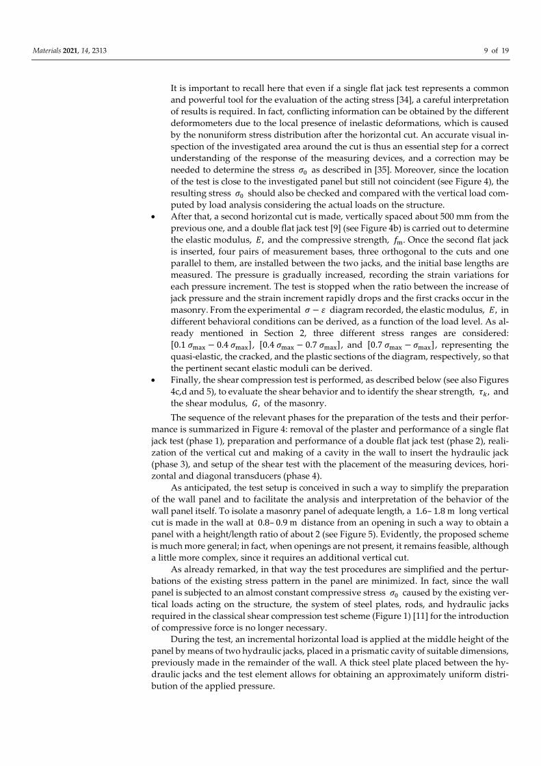
Figure 5. Proposed test arrangement for the evaluation of the shear behavior of masonry panels of
length �, height 2ℎ and thickness � subjected to the horizonal load �.
Considering that the panel is clamped to the remaining part of the structure at both
ends and that the load is applied at the middle of the panel, it is assumed that the two
approximately square subpanels are subjected to nearly symmetrical shear and compres-
sion forces. Different boundary conditions for the upper and lower parts of the panel may
cause a lack of symmetry in shear distribution between the two halves of the panel, which
should be considered in the analysis of the results [13].
During the test, the horizontal load is gradually applied with intermediate unloading
steps, until diagonal cracks occur in one or both the two subpanels, and the maximum
load value is thus recorded. Deformations are continuously monitored during the test by
a set of 14 linear variable displacement transducer (LVDT) inductive sensors. Eight
Materials 2021, 14, 2313 11 of 19
LVDTs, placed along the diagonals of the two opposite faces of the subpanels, measure
the corresponding relative displacements, while the remaining six transducers, placed
along the free lateral side, with a symmetrical arrangement with respect to its vertical
centerline, measure horizontal displacements. The test arrangement with the location of
measuring devices is shown in Figure 5.
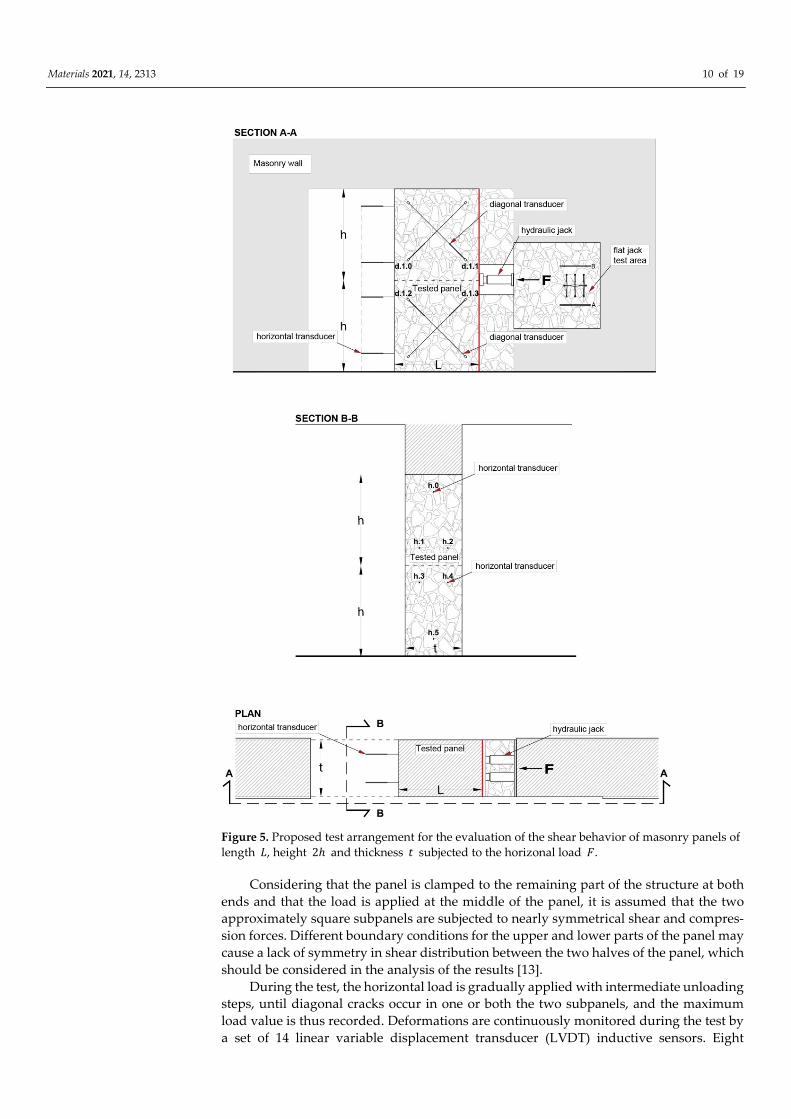
Once the test is concluded, the panel can be easily repaired and suitably strength-
ened, adopting appropriate techniques, like addition of steel plates or reinforced concrete
exterior layers, duly connected to the masonry. An example is given in Figure 6, where
they are represented by the restoring phases of the wall: repair of cut and cavity (Figure
6a), insertion of threaded or reinforcing steel bars (Figure 6a,b), application of the rein-
forcing steel mesh (Figure 6c), and final grouting of the concrete layer (Figure 6d). If nec-
essary, a more effective strengthening technique can include the insertion of additional
steel plates on both sides of the panel.
(a) (b)
(c) (d)
Figure 6. Strengthened technique adopted to restore the tested walls: repair of cut and cavity (a),
insertion of threaded or reinforcing steel bars (b), application of the reinforcing steel mesh (c), and
final grouting of the concrete layer (d).
Materials 2021, 14, 2313 12 of 19
3.2. Results
The first results obtained from the proposed test procedure are illustrated in this sec-
tion for three stone masonry panels tested during the already-cited experimental cam-
paign carried out by the authors. The proposed methodology is general and can be easily
extended also to a different masonry typology. In fact, a test has already been carried out
also on solid brick masonry, but results will be presented only for the masonry panels of
the same typology.
The stone masonry panels belong to three different buildings, built in Florence at the
beginning of the 19th century:
Panel A is located in the three-story masonry building housing the kindergarten and
primary school “Giotto,”
Panel B is located in the four-story masonry building of the primary school “Cairoli,”
and
Panel C is located in the four-story masonry building of the primary school “Nicco-
lini.”
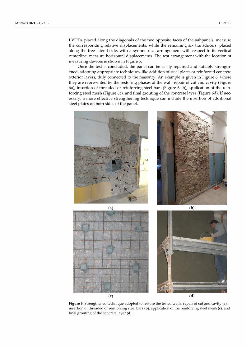
The three masonry panels are shown in Figure 7, while the main characteristics
(height, ℎ; length, �; and thickness, �; of the panel) are summarized in Table 3.
(a) (b) (c)
Figure 7. Tested stone masonry panels, Giotto (a), Cairoli (b), and Niccolini (c).
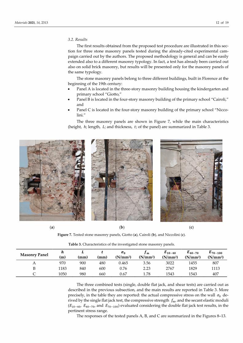
Table 3. Characteristics of the investigated stone masonry panels.
Masonry Panel �
(m)
�
(mm)
�
(mm)
��
(N/mm2)
��
(N/mm2)
������ ������ �������
(N/mm2) (N/mm2) (N/mm2)
A 970 900 480 0.465 3.56 3022 1455 807
B 1183 840 600 0.76 2.23 2767 1829 1113
C 1050 980 660 0.67 1.78 1543 1543 407
The three combined tests (single, double flat jack, and shear tests) are carried out as
described in the previous subsection, and the main results are reported in Table 3. More
precisely, in the table they are reported: the actual compressive stress on the wall �� de-
rived by the single flat jack test, the compressive strength ��, and the secant elastic moduli
(������, ������, and �������) evaluated considering the double flat jack test results, in the
pertinent stress range.
The responses of the tested panels A, B, and C are summarized in the Figures 8–13.
Materials 2021, 14, 2313 13 of 19
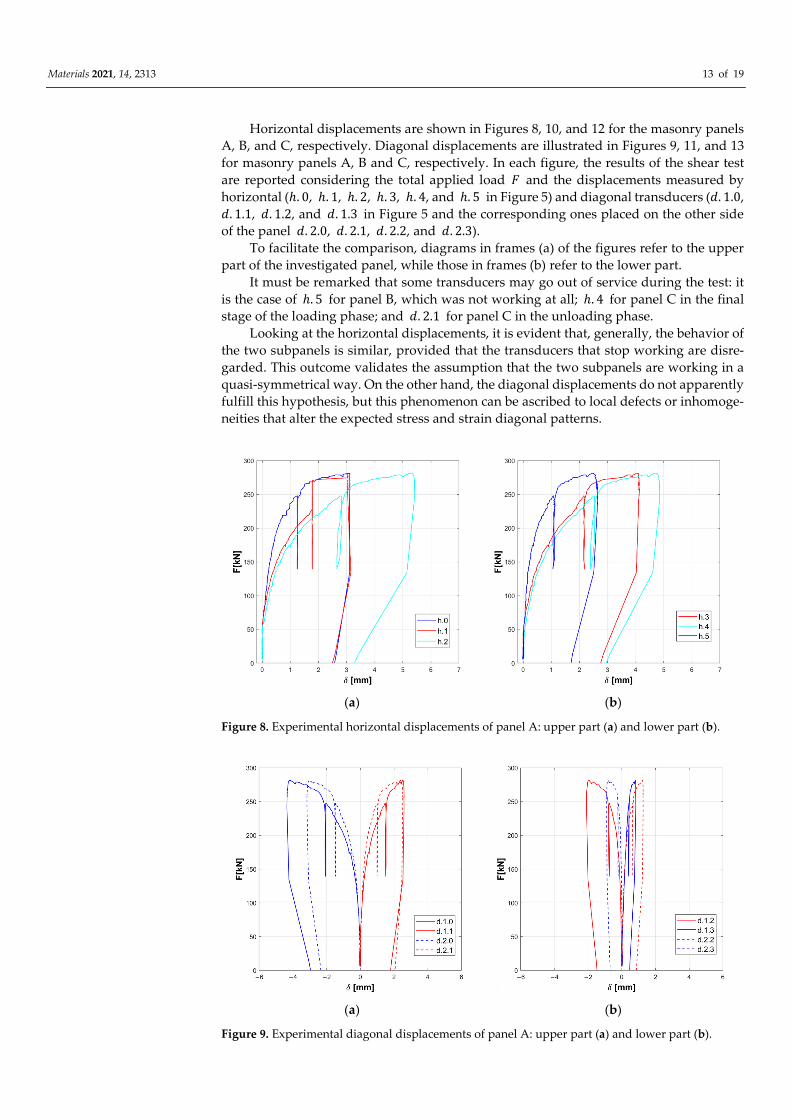
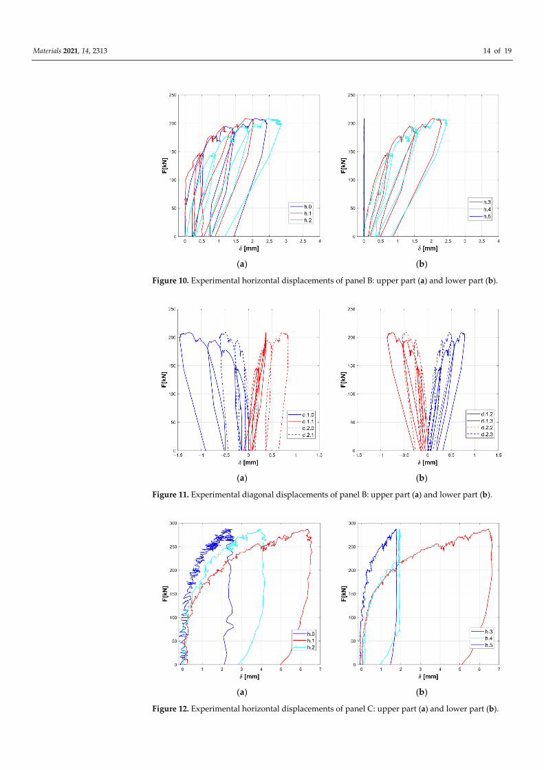
Horizontal displacements are shown in Figures 8, 10, and 12 for the masonry panels
A, B, and C, respectively. Diagonal displacements are illustrated in Figures 9, 11, and 13
for masonry panels A, B and C, respectively. In each figure, the results of the shear test
are reported considering the total applied load � and the displacements measured by
horizontal (ℎ. 0, ℎ. 1, ℎ. 2, ℎ. 3, ℎ. 4, and ℎ. 5 in Figure 5) and diagonal transducers (�. 1.0,
�. 1.1, �. 1.2, and �. 1.3 in Figure 5 and the corresponding ones placed on the other side
of the panel �. 2.0, �. 2.1, �. 2.2, and �. 2.3).
To facilitate the comparison, diagrams in frames (a) of the figures refer to the upper
part of the investigated panel, while those in frames (b) refer to the lower part.
It must be remarked that some transducers may go out of service during the test: it
is the case of ℎ. 5 for panel B, which was not working at all; ℎ. 4 for panel C in the final
stage of the loading phase; and �. 2.1 for panel C in the unloading phase.
Looking at the horizontal displacements, it is evident that, generally, the behavior of
the two subpanels is similar, provided that the transducers that stop working are disre-
garded. This outcome validates the assumption that the two subpanels are working in a
quasi-symmetrical way. On the other hand, the diagonal displacements do not apparently
fulfill this hypothesis, but this phenomenon can be ascribed to local defects or inhomoge-
neities that alter the expected stress and strain diagonal patterns.
(a) (b)
Figure 8. Experimental horizontal displacements of panel A: upper part (a) and lower part (b).
(a) (b)
Figure 9. Experimental diagonal displacements of panel A: upper part (a) and lower part (b).
Materials 2021, 14, 2313 14 of 19
(a) (b)
Figure 10. Experimental horizontal displacements of panel B: upper part (a) and lower part (b).
(a) (b)
Figure 11. Experimental diagonal displacements of panel B: upper part (a) and lower part (b).
(a) (b)
Figure 12. Experimental horizontal displacements of panel C: upper part (a) and lower part (b).
Materials 2021, 14, 2313 15 of 19
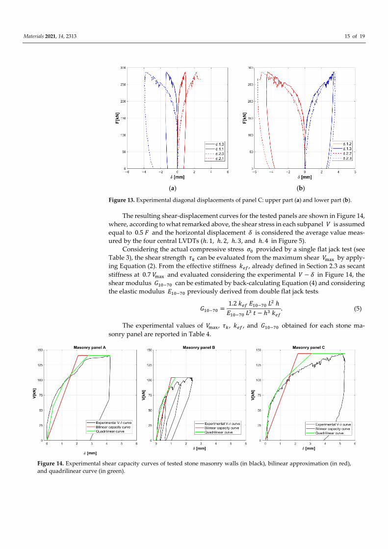
(a) (b)
Figure 13. Experimental diagonal displacements of panel C: upper part (a) and lower part (b).
The resulting shear-displacement curves for the tested panels are shown in Figure 14,
where, according to what remarked above, the shear stress in each subpanel � is assumed
equal to 0.5 � and the horizontal displacement � is considered the average value meas-
ured by the four central LVDTs (ℎ. 1, ℎ. 2, ℎ. 3, and ℎ. 4 in Figure 5).
Considering the actual compressive stress �� provided by a single flat jack test (see
Table 3), the shear strength �� can be evaluated from the maximum shear ���� by apply-
ing Equation (2). From the effective stiffness ���, already defined in Section 2.3 as secant
stiffness at 0.7 ���� and evaluated considering the experimental � − � in Figure 14, the
shear modulus ������ can be estimated by back-calculating Equation (4) and considering
the elastic modulus ������ previously derived from double flat jack tests:
������ =1.2 ��� ������ �� ℎ
������ �� � − ℎ� ���
. (5)
The experimental values of ����, �� , ��� , and ������ obtained for each stone ma-
sonry panel are reported in Table 4.
Figure 14. Experimental shear capacity curves of tested stone masonry walls (in black), bilinear approximation (in red),
and quadrilinear curve (in green).
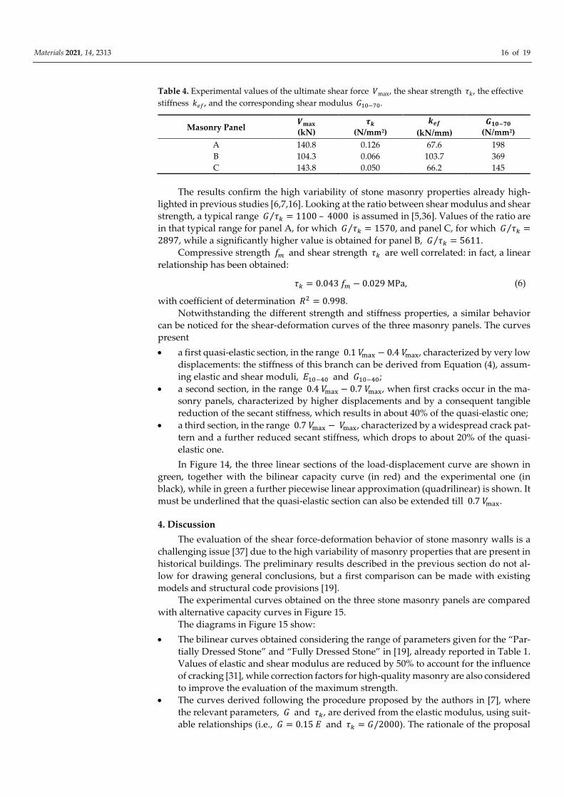
Materials 2021, 14, 2313 16 of 19
Table 4. Experimental values of the ultimate shear force �max, the shear strength ��, the effective
stiffness ���, and the corresponding shear modulus ������.
Masonry Panel ����
(kN)
��
(N/mm2)
���
(kN/mm)
������
(N/mm2)
A 140.8 0.126 67.6 198
B 104.3 0.066 103.7 369
C 143.8 0.050 66.2 145
The results confirm the high variability of stone masonry properties already high-
lighted in previous studies [6,7,16]. Looking at the ratio between shear modulus and shear
strength, a typical range � ��⁄ = 1100 – 4000 is assumed in [5,36]. Values of the ratio are
in that typical range for panel A, for which � ��⁄ = 1570, and panel C, for which � ��⁄ =
2897, while a significantly higher value is obtained for panel B, � ��⁄ = 5611.
Compressive strength �� and shear strength �� are well correlated: in fact, a linear
relationship has been obtained:
�� = 0.043 �� − 0.029 MPa, (6)
with coefficient of determination �� = 0.998.
Notwithstanding the different strength and stiffness properties, a similar behavior
can be noticed for the shear-deformation curves of the three masonry panels. The curves
present
a first quasi-elastic section, in the range 0.1 ���� − 0.4 ����, characterized by very low
displacements: the stiffness of this branch can be derived from Equation (4), assum-
ing elastic and shear moduli, ������ and ������;
a second section, in the range 0.4 ���� − 0.7 ����, when first cracks occur in the ma-
sonry panels, characterized by higher displacements and by a consequent tangible
reduction of the secant stiffness, which results in about 40% of the quasi-elastic one;
a third section, in the range 0.7 ���� − ����, characterized by a widespread crack pat-
tern and a further reduced secant stiffness, which drops to about 20% of the quasi-
elastic one.
In Figure 14, the three linear sections of the load-displacement curve are shown in
green, together with the bilinear capacity curve (in red) and the experimental one (in
black), while in green a further piecewise linear approximation (quadrilinear) is shown. It
must be underlined that the quasi-elastic section can also be extended till 0.7 ����.
4. Discussion
The evaluation of the shear force-deformation behavior of stone masonry walls is a
challenging issue [37] due to the high variability of masonry properties that are present in
historical buildings. The preliminary results described in the previous section do not al-
low for drawing general conclusions, but a first comparison can be made with existing
models and structural code provisions [19].
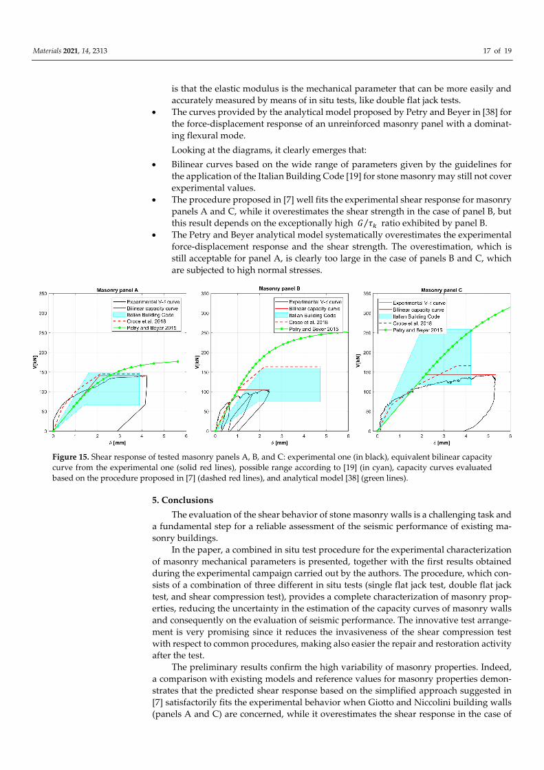
The experimental curves obtained on the three stone masonry panels are compared
with alternative capacity curves in Figure 15.
The diagrams in Figure 15 show:
The bilinear curves obtained considering the range of parameters given for the “Par-
tially Dressed Stone” and “Fully Dressed Stone” in [19], already reported in Table 1.
Values of elastic and shear modulus are reduced by 50% to account for the influence
of cracking [31], while correction factors for high-quality masonry are also considered
to improve the evaluation of the maximum strength.
The curves derived following the procedure proposed by the authors in [7], where
the relevant parameters, � and ��, are derived from the elastic modulus, using suit-
able relationships (i.e., � = 0.15 � and �� = �/2000). The rationale of the proposal
Materials 2021, 14, 2313 17 of 19
is that the elastic modulus is the mechanical parameter that can be more easily and
accurately measured by means of in situ tests, like double flat jack tests.
The curves provided by the analytical model proposed by Petry and Beyer in [38] for
the force-displacement response of an unreinforced masonry panel with a dominat-
ing flexural mode.
Looking at the diagrams, it clearly emerges that:
Bilinear curves based on the wide range of parameters given by the guidelines for
the application of the Italian Building Code [19] for stone masonry may still not cover
experimental values.
The procedure proposed in [7] well fits the experimental shear response for masonry
panels A and C, while it overestimates the shear strength in the case of panel B, but
this result depends on the exceptionally high � ��⁄ ratio exhibited by panel B.
The Petry and Beyer analytical model systematically overestimates the experimental
force-displacement response and the shear strength. The overestimation, which is
still acceptable for panel A, is clearly too large in the case of panels B and C, which
are subjected to high normal stresses.
Figure 15. Shear response of tested masonry panels A, B, and C: experimental one (in black), equivalent bilinear capacity
curve from the experimental one (solid red lines), possible range according to [19] (in cyan), capacity curves evaluated
based on the procedure proposed in [7] (dashed red lines), and analytical model [38] (green lines).
5. Conclusions
The evaluation of the shear behavior of stone masonry walls is a challenging task and
a fundamental step for a reliable assessment of the seismic performance of existing ma-
sonry buildings.
In the paper, a combined in situ test procedure for the experimental characterization
of masonry mechanical parameters is presented, together with the first results obtained
during the experimental campaign carried out by the authors. The procedure, which con-
sists of a combination of three different in situ tests (single flat jack test, double flat jack
test, and shear compression test), provides a complete characterization of masonry prop-
erties, reducing the uncertainty in the estimation of the capacity curves of masonry walls
and consequently on the evaluation of seismic performance. The innovative test arrange-
ment is very promising since it reduces the invasiveness of the shear compression test
with respect to common procedures, making also easier the repair and restoration activity
after the test.
The preliminary results confirm the high variability of masonry properties. Indeed,
a comparison with existing models and reference values for masonry properties demon-
strates that the predicted shear response based on the simplified approach suggested in
[7] satisfactorily fits the experimental behavior when Giotto and Niccolini building walls
(panels A and C) are concerned, while it overestimates the shear response in the case of
Materials 2021, 14, 2313 18 of 19
Cairoli’s wall (panel B), which is characterized by an exceptionally high value of the ratio
� ��⁄ .
A satisfactory correlation is found between the experimental values of compressive
and shear strength, but further experimental results are needed to draw more general
conclusions and to confirm the validity of the obtained linear relationship. This will be
one of the subjects of an ongoing experimental campaign.
Author Contributions: Conceptualization, M.L.B., P.C., P.F., F.L., and B.P.; methodology, M.L.B.,
P.C., P.F., F.L., and B.P.; software, M.L.B., P.C., P.F., F.L., and B.P.; validation, M.L.B., P.C., P.F., F.L.,
and B.P.; resources, P.C.; writing—original draft preparation, M.L.B., P.C., P.F., F.L., and B.P.; writ-
ing—review and editing, M.L.B., P.C., P.F., F.L., and B.P.; funding acquisition, P.C. All authors have
read and agreed to the published version of the manuscript.
Funding: This research received no external funding.
Institutional Review Board Statement: Not applicable.
Informed Consent Statement: Not applicable.
Data Availability Statement: The data presented in this study are available on request from the
corresponding author. The data are not publicly available as they cannot be used for commercial
purposes.
Acknowledgments: The present research was carried out in the framework of a research agreement
between the Municipality of Florence and the Department of Civil and Industrial Engineering, Uni-
versity of Pisa. The authors acknowledge the mayor of Florence and the staff of the Engineering
Department of the Municipality of Florence.
Conflicts of Interest: The authors declare no conflicts of interest.
References
1. Croce, P.; Landi, F.; Formichi, P. Probabilistic seismic assessment of masonry buildings. Buildings 2019, 9, 237, doi:10.3390/build-
ings9120237.
2. Croce, P.; Beconcini, M.L.; Formichi, P.; Landi, F.; Puccini, B.; Zotti, V. Bayesian Methodology for Probabilistic Description of
Mechanical Parameters of Masonry Walls. ASCE-ASME J. Risk Uncertain. Eng. Syst. Part A Civ. Eng. 2021, 7, 04021008,
doi:10.1061/AJRUA6.0001110.
3. Lourenço, P.B. Computations on historic masonry structures. Prog. Struct. Eng. Mater. 2002, 4, 301–319, doi:10.1002/pse.120.
4. Beconcini, M.L.; Croce, P.; Marsili, F.; Muzzi, M.; Rosso, E. Probabilistic reliability assessment of a heritage structure under
horizontal loads. Probabilistic Eng. Mech. 2016, 45, 198–211, doi:10.1016/j.probengmech.2016.01.001.
5. Croce, P.; Beconcini, M.L.; Formichi, P.; Cioni, P.; Landi, F.; Mochi, C.; Giuri, R. Influence of mechanical parameters on nonlinear
static analysis of masonry walls: A relevant case study. Procedia Struct. Integr. 2018, 11, 331–338, doi:10.1016/j.prostr.2018.11.043.
6. Beconcini, M.L.; Cioni, P.; Croce, P.; Formichi, P.; Landi, F.; Mochi, C. Influence of shear modulus and drift capacity on non-
linear static analysis of masonry buildings. In IABSE Symposium, Guimaraes 2019: Towards a Resilient Built Environment Risk and
Asset Management, Report; International Association for Bridge and Structural Engineering (IABSE): Zurich, Switzerland, 2019;
pp. 876–883. ISBN 978-385748163-5.
7. Croce, P.; Beconcini, M.L.; Formichi, P.; Cioni, P.; Landi, F.; Mochi, C.; De Lellis, F.; Mariotti, E.; Serra, I. Shear modulus of
masonry walls: A critical review. Procedia Struct. Integr. 2018, 11, 339–346, doi:10.1016/j.prostr.2018.11.044.
8. Bosiljkov, V.Z.; Totoev, Y.Z.; Nichols, J.M. Shear modulus and stiffness of brickwork masonry: An experimental perspective.
Struct. Eng. Mech. 2005, 20, 21–43.
9. ASTM. Standard Test Method for In-Situ Measurement of Masonry Deformability Properties Using the Flat Jack Method, ASTM C 1197-
14a; ASTM: West Conshohocken, PA, USA, 2014.
10. ASTM. Standard Test Method for Diagonal Tension (Shear) in Masonry Assemblages. In Annual Book of ASTM Standards, ASTM
E 519-02; ASTM International: West Conshohocken, PA, USA, 2002.
11. Sheppard, P.F. In situ test of the shear strength and deformability of an 18th century stone and brick masonry wall. In Proceed-
ings of the 7th International Brick Masonry Conference, Melbourne, Australia, 17–20 February 1985; Volume 1, pp. 149–160.
12. Shing, P.; Noland, H.S.; Klamerus, E.;Schuller, M. Response of Single-Story Reinforced Masonry Shear Walls to In-Plane Lateral Loads;
Report No.3.1(a-2); National Science Foundation: Washington, DC, USA, January 1991.
13. Corradi, M.; Borri, A.; Vignoli, A. Experimental study on the determination of strength of masonry walls. Constr. Build. Mater.
2003, 17, 325–337, doi:10.1016/S0950-0618(03)00007-2.
14. Brignola, A.; Frumento, S.; Lagomarsino, S.; Podestà, S. Identification of shear parameters of masonry panels through the in-
situ diagonal compression test. Int. J. Archit. Herit. 2009, 3, 52–73, doi:10.1080/15583050802138634.
Materials 2021, 14, 2313 19 of 19
15. Vasconcelos, G.; Lourenço, P.B. In-Plane Experimental Behavior of Stone Masonry Walls under Cyclic Loading. J. Struct. Eng.
2009, 135, 1269–1277, doi:10.1061/(ASCE)ST.1943-541X.0000053.
16. Vanin, F.; Zaganelli, D.; Penna, A.; Beyer, K. Estimates for the stiffness, strength and drift capacity of stone masonry walls based
on 123 quasi-static cyclic tests reported in the literature. Bull. Earthq. Eng. 2017, 15, 5435–5479, doi:10.1007/s10518-017-0188-5.
17. Zhang, S.; Richart, N.; Beyer, K. Numerical evaluation of test setups for determining the shear strength of masonry. Mater.
Struct. 2018, 51, 110, doi:10.1617/s11527-018-1236-6.
18. Borri, A.; Corradi, M.; De Maria, A.; Sisti, R. Calibration of a visual method for the analysis of the mechanical properties of
historic masonry. Procedia Struct. Integr. 2018, 11, 418–427, doi:10.1016/j.prostr.2018.11.054.
19. Italian Public Works Council. Memorandum for Application of Italian Building Code, N. 7; Italian Official Journal, Istituto Poligrafico
e Zecca dello Stato: Rome, Italy, 2019. (In Italian).
20. Croce, P.; Marsili, F.; Klawonn, F.; Formichi, P.; Landi, F. Evaluation of statistical parameters of concrete strength from second-
ary experimental test data. Constr. Build. Mater. 2018, 163, 343–359, doi: 10.1016/j.conbuildmat.2017.11.001.
21. Croce, P.; Beconcini, M.L.; Formichi, P.; Landi, F.; Puccini, B.; Zotti, V. Evaluation of partial safety factors for the structural
assessment of existing masonry buildings. In 18th Probabilistic Workshop, Lecture Notes in Civil Engineering 153, 2021, Springer
Nature Switzerland. doi: https://doi.org/10.1007/978-3-030-73616-3_25.
22. Turnšek, V.; Ĉaĉoviĉ, F. Some experimental results on the strength of brick masonry walls. In Proceedings of the 2nd International
Brick Masonry Conference; British Ceramic Research Association: Stoke-on-Trent, UK, 1971; pp. 149–156.
23. Tomazevic, M. Shear resistance of masonry walls and Eurocode 6: Shear versus tensile strength of masonry. Mater. Struct. 2009,
42, 889–907, doi:10.1617/s11527-008-9430-6.
24. RILEM TC. 1994. 76-LUM. Diagonal tensile strength tests of small wall specimens. In RILEM, Recommendations for the Testing
and Use of Constructions Materials; E&FN SPON: London, UK, 1991; pp. 488–489.
25. Borri, A.; Castori, G.; Corradi, M. Determination of Shear Strength of Masonry Panels Through Different Tests. Int. J. Archit.
Herit. Conserv. Anal. Restor. 2013, 913–927, doi:10.1080/15583058.2013.804607.
26. Wilding, B.V.; Beyer, K. The effective stiffness of modern unreinforced masonry walls. Earthq. Eng. Struct. Dyn. 2018, 47, 1683–
1705, doi:10.1002/eqe.3035.
27. Croce, P.; Beconcini, M.L.; Formichi, P.; Landi, F.; Puccini, B.; Zotti, V. Seismic risk evaluation of existing masonry buildings:
Methods and uncertainties. In 20th IABSE Congress, New York City 2019: The Evolving Metropolis; IABSE: Zurich, Switzerland,
2019; pp. 2510–2515, ISBN 978-385748165-9.
28. Beconcini, M.L.; Cioni, P.; Croce, P.; Formichi, P.; Landi, F.; Mochi, C. Non-linear static analysis of masonry buildings under
seismic actions. In Proceedings of the 12th International Multi-Conference on Society, Cybernetics and Informatics: IMSCI, Or-
lando, FL, USA, 8–11 July 2018; Volumn 1, pp. 126–131, ISBN: 978-194176385-8. Available online: http://www.iiisci.org/Jour-
nal/CV$/sci/pdfs/EA239AY18.pdf (accessed on 24/04/2021).
29. Marques, R.; Lourenço, P.B. Possibilities and comparison of structural component models for the seismic assessment of modern
unreinforced masonry buildings. Comput. Struct. 2011, 89, 2079–2091, doi:10.1016/j.compstruc.2011.05.021.
30. Lagomarsino, S.; Penna, A.; Galasco, A.; Cattari, S. TREMURI program: An equivalent frame model for the nonlinear seismic
analysis of masonry buildings. Eng. Struct. 2013, 56, 1787–1799, doi:10.1016/j.engstruct.2013.08.002.
31. EN 1998-1:2004 Eurocode 8: Design of Structures for Earthquake Resistance—Part 1: General Rules, Seismic Actions and Rules for Build-
ings. European Committee for Standardization (CEN): Brussels, Belgium, 2004.
32. ASTM. Standard Test Method for In Situ Compressive Stress Within Solid Unit Masonry Estimated Using Flatjack Measurements. ASTM
C1196-14a: West Conshohocken, PA, USA, 2014.
33. RILEM TC 177-MDT. RILEM Recommendation MDT. D. 4: In-situ stress tests based on the flat jack. Mater. Struct. 2004, 37, 491-
496.
34. Binda, L.; Tiraboschi, C. Fiat-Jack Test: A slightly destructive technique for the diagnosis of brick and stone masonry structures.
Int. Zeltschrift Für Bauinstandsetz. Und Baudenkrnalpflege 1999, 5, 449–472, doi:10.1515/rbm-1999-5404.
35. Ronca, P.; Tiraboschi, С.; Binda, L. In-situ flat-jack tests matching new mechanical interpretations. In Proceedings of the 11th
International Brick/Block Masonry Conference, Shanghai, China, 14–16 October 1997; pp. 357–366.
36. Tomažević, M. Earthquake-Resistant Design of Masonry Buildings; Series on Innovation in Structures and Construction: London,
UK, 1999; Volumn 1.
37. Shenghan Zhang, S.; Mousavi, S.M.T.; Nicolas Richart, N.; Molinari, J.-F.; Beyer, K. Micro-mechanical finite element modeling
of diagonal compression test for historical stone masonry structure. Int. J. Solids Struct. 2017, 112, 122–132, doi:10.1016/j.ijsol-
str.2017.02.014.
38. Petry, S.; Beyer, K. Force–displacement response of in-plane-loaded URM walls with a dominating flexural mode. Earthq. Eng.
Struct. Dyn. 2015, 44, 2551–2573, doi:10.1002/eqe.2597.