experimental evaluation of reinforced … int. j. struct. & civil engg. res. 2013 y v ladi and p...
TRANSCRIPT

219
Int. J. Struct. & Civil Engg. Res. 2013 Y V Ladi and P M Mohite, 2013
EXPERIMENTAL EVALUATION OF REINFORCEDCONCRETE BEAM RETROFITTED WITH
FERROCEMENTY V Ladi1* and P M Mohite2
1 Department of Civil Engineering, Rajarambapu Institute of Technology, Rajaramnagar.2 Department of Civil Engineering, Rajarambapu Institute of Technology, Rajaramnagar.
*Corresponding author:Y V Ladi, [email protected]
ISSN 2319 – 6009 www.ijscer.comVol. 2, No. 3, August 2013
© 2013 IJSCER. All Rights Reserved
Int. J. Struct. & Civil Engg. Res. 2013
Research Paper
INTRODUCTIONCivil engineering structures are an importantelement of infrastructure and provide goodservice to the user they experience distresseson account of reason and need ofstrengthening and retrofitting to bring them intofunctional use again. Deterioration of concretestructures is one of the major problems in
construction industry today. Today variousretrofitting techniques are available in field likeplate bonding. In plate bonding ferrocementone of the retrofitting technique to improve thestructural performance of deterioratedstructure. Ferrocement is a type of thin wallreinforced concrete commonly constructed ofhydraulic cement mortar reinforced with closely
In present RC beams initially stressed to a prefixed percentage of the ultimate load are retrofittedwith ferrocement to improve the performance of RC beam in both shear and flexure, the weldedwire mesh is wrapped around the beam in U shape. An experimental work is conducted toevaluate the performance of RC beam retrofitted with ferrocement. In experimental work total25 beams are casted, from that three beams are control beams. Six beams are shear deficientbeam and retrofitted with single and double layer of wire mesh at 00 and 450 orientation.Remaining sixteen beams are distressed at 60%, 80% of ultimate load and retrofitted withferrocement in number of layers at various orientation. Such distressed beams are divided infour groups. In one group distressed beams are retrofitted with single layer of wire mesh at 00.Inanother three group retrofitting are worked out with single layer of wire mesh at 450, doublelayers of wire mesh at 00, double layers of wire mesh at 450, respectively. The load deflectioncharacteristics and mode of failure are studied. The test results indicate that, when beamretrofitted with wire mesh in layers at orientations, it significantly increases the load carryingcapacity, first crack load, stiffness but deflection is decreases in both flexural and shearstrengthening.
Keywords:Ferrocement, Retrofitting, Jacketing, Wire mesh, Beams, Ultimate load

220
Int. J. Struct. & Civil Engg. Res. 2013 Y V Ladi and P M Mohite, 2013
spaced layers of continuous and relativelysmall size wire mesh. In its role as a thinreinforced concrete product and as laminatedcement based composite, ferrocement hasfound itself in numerous applications both innew structures, repairs and rehabilitation ofexisting structures. Compared with theconventional reinforced concrete,reinforcement in ferrocement in two directions.Due to this two direction reinforcement it hashomogeneous-isotopic properties in twodirections. Benefiting from its usually highreinforcement ratio, ferrocement generally hasa tensile strength and modulus of rupture.
CONSTITUENT MATERIALSOF FERROCEMENTa) Cement: The cement should comply with
Indian Standards. The cement should befresh, of uniform consistency and free oflumps.
b) Fine aggregate: Normal weight fineaggregate passing IS 2.36 mm sieve usedin jacketing. Grading of the sand is to besuch that a mortar of specified proportionsis produced with a uniform distribution ofthe aggregate.
c) Water: Water used in the mixing is to befresh and free from any organic and harmfulsolution. Portable water is fit for use asmixing water as wel l as curing forferrocement structures.
d) Reinforcing Mesh: One of the essentialcomponents of the ferrocement is wiremesh. The function of the wire mesh andreinforcing rod in the first instant is to act aslath providing the form and to support themortar in its green state.
Paramasivam et al. (1998)has been carriedout to strengthening of reinforced concretebeam with ferrocement laminates.Investigation into the transfer of forces acrossthe concrete/ferrocement interface, the effectof the level of damage sustained by theoriginal beams prior to repair, and the resultsof repeated loading on the performance of thestrengthened beams are discussed. Theresults show that ferrocement is a viablealternative for strengthening and rehabilitationsof reinforced concrete structures.
An experimental investigation has beencarried out to study the effect of ferrocementjacketing on the strength and behavior ofdistressed reinforced concrete flexuralelements by Ganeshan et al. (2005) Thereinforced concrete specimens are subjectedto different stages of loading, viz., 0.7, 0.8 and0.9 times their ultimate load carrying capacity.Such distressed specimens are retrofitted byferrocement having different values of volumefraction of mesh reinforcement viz, 0.26, 0.52and 0.78%. The results indicate that retrofittedbeam improves the load carrying capacity,stiffness and energy absorption capacity of thebeam.
Sheela et al. (2009) made an attempt hasbeen made to determine the effect of numberof layers of wire mesh on the performance ofthe beams retrofitted using ferrocement. Also,the effects of number of layers of GFRP on theperformance of retrofitted beams are studied.From the experimental investigation it wasfound that the ultimate load carrying capacityof beams retrofitted with ferrocement havingone, two and three layers of wire meshincreased by 6.25%, 50% and 81.25% and

221
Int. J. Struct. & Civil Engg. Res. 2013 Y V Ladi and P M Mohite, 2013
that of GFRP retrofitted beams with 1, 2 and 3layers increased by 50%, 68.75% and81.25%, respectively.
Rafeeqi (2011) focused on shortinvestigation of theoretical prediction modelsfor plain concrete confined with ferrocement.The proposed model posses the capability ofpredicting strength of plain concrete, confinedwith ferrocement for all the possible andpractical method of confinement by way of,integrally cast mesh layer, mesh layers inprecast shell and wrapped mesh layer onprecast core.
Reddy (2011) investigate, the experimentalprogram consists of casting and preloadingof 24 deficient reinforced concrete beams.The preloading levels adopted in thisinvestigation are 70%, 90% and ultimate.Ferrocement jacketing is done with 2, 4, 6 and8 layers of woven wire mesh. After investigationtest results indicate that the shear failure wastransferred to flexural failure in retrofittedbeams.
Patil et al. (2012)studied RC beams initiallystressed to a prefixed percentage of the safeload are retrofitted using ferrocement toincrease the strength of beam in both shearand flexure, beams are distressed 60% ,80%of ultimate load. The chicken mesh is placedalong the longitudinal axis of the beam. Afterexperimental work researcher concluded thatchicken mesh stressed with 60% afterretrofitting the stressed beam has the highestload carrying capacity with chicken mesh andalso a significant increase in the ductility ratio.
OBJECTIVES OF STUDY1. To find out an effect on strength of the RC
beam retrofitted with ferrocement in singleand double layer at 00,450 orientations,wrapping on three sides by comparing theload carrying capacity of the retrofittedbeam and control beam.
2. To determine the flexural rigidity of the RCbeam retrofitted with ferrocement in singleand double layer at 00,450 orientations,wrapping on three sides by measuringdeflection of the retrofitted beam andcompare with control beam.
3. To observe behavior of the RC beamretrofitted with ferrocement in single anddouble layer at 00,450 orientations,wrapping on three sides and control beamwith respect to first crack load, crack patternand crack width.
EXPERIMENTAL PROGRAMMaterials
The experimental work consists of casting andtesting of 25 simply supported RC beams of100 mm x 150 mm cross section and 1000mm length. The materials used in theinvestigation are given below:
CementOrdinary portland cement of 43 grade used.The specific gravity of cement is 3.15.
Fine Aggregate
Locally available natural river sand was usedas fine aggregate. The specific gravity of sandwas found to be 2.66 and fineness Moduluswas 2.55 confirming to zone II.
Coarse Aggregate
Machine crushed angular shaped, maximum20 mm size aggregate was used. The specificgravity was found to be 2.96 and finenessmodulus of coarse aggregate was 7.49.

222
Int. J. Struct. & Civil Engg. Res. 2013 Y V Ladi and P M Mohite, 2013
Steel
The longitudinal steel used was 8 mm diameterHYSD TMT bars. Mild steel bars of 6 mmdiameter was used as lateral stirrups spacedat 150 mm c/c. Details of reinforcement asshown in Figures 1 and 2.
Casting
In the casting process, all the ingredients werefirst mixed in dry condition, to the dry mix;calculated quantity of water was added andthoroughly mixed to get a uniform mix. Shutteringoil was applied on the inner face of plywoodmould and the reinforcement cage was placedin the position. Concrete was poured in threelayers was compacted by tamping rod as shownin Figure 3. The specimens were cured incuring tank for 28 days.
Figure 1: Beam ReinforcementDetails with Shear Stirrups
Figure 2: Beam reinforcementdetails without shear stirrups
Wire MeshMS welded wire mesh of square grid wasused. The size of opening was 16 mm x 16mm. The diameter of wire mesh was 0.8 mm.
Mix Selection
Indian standard code 10262 – 2009 was usedto arrive final mix proportion. The final mixproportions adopted in the investigation are1:2.16:3.75 with w/c ratio 0.55 for M 20 gradeof concrete.
WaterClean potable water was used for mixing andcuring.
Figure 3: Casting of Beam Specimen
TESTING PROCEDURENineteen beams were designed and castedto fail in flexure only. Six beams were castedas a shear deficient means without shearstirrups. After completion of curing time,beams were tested using universal testingmachine of 600 KN capacity with two pointloading. The deflections at three points wererecorded by using dial gauge having leastcount 0.01 mm at every 2.5 KN increment ofload. Out of twenty five beams three beams

223
Int. J. Struct. & Civil Engg. Res. 2013 Y V Ladi and P M Mohite, 2013
were tested as a control beam to find outultimate load of the beam. Eight beams weredistressed by 60% of ultimate load. Balanceeight beams were distressed by 80% ofultimate load. Cracking pattern in control beamand experimental set up is shown in Figure 4.
mesh was tightened using binding wires. Athick cement paste was applied as bondingagent before application of mortar in order toget a good bond. Plastering was done withcement mortar having the ratio of 1:3 by weightand water cement ratio was kept as 0.5. The20 mm thickness of mortar was applied on thebeam surface. The retrofitted beams werecured for 28 days in curing tank. FollowingFigure 5 shows process of retrofitting.
Figure 4: Test set up fortwo point loading
PROCESS OF RETROFITTINGAfter first stage of loading, the distressedbeams were retrofitted by using ferrocementjacketing. Ferrocement is another form ofreinforced concrete in which cement sandmortar is reinforced with closely spaced MSwelded wire mesh. In this study, square gridMS welded wire mesh (wire mesh of 16 mm x16 mm x 0.8 mm diameter) was used for allspecimens in single, double layer at 00 and450 orientations. The surfaces of thedistressed beam were roughened by usinghacker and wire mesh was wound over it. The
Figure 5: Process of Retrofitting

224
Int. J. Struct. & Civil Engg. Res. 2013 Y V Ladi and P M Mohite, 2013
Table 1: Ferrocement Configuration for Retrofitting
Particulars % of Distress Designation
Control Beam - CB1, CB2, CB3
Single layer 60 % R1 = 60% Single Layer 00
Single layer 80 % R2 = 80% Single Layer 00
Double Layer 60 % R3 = 60% Double Layer 00
Double Layer 80 % R4 = 80% Double Layer 00
Single layer 60 % R5 = 60% Single Layer 450
Single layer 80 % R6 = 80% Single Layer 450
Double Layer 60 % R7 = 60% Double Layer 450
Double Layer 80 % R8 = 80% Double Layer 450
Double Layer Shear deficient S1= Shear Double Layer 00
Double Layer Shear deficient S2= Shear Double Layer 450
Single layer Shear deficient S3 = Shear Single Layer 450
FERROCEMENTCONFIGURATION FORRETROFITTING60% and 80% distressed beams wereretrofitted in single, double layers of wire meshat 00 and 450 orientations. Following Table 1shows ferrocement configuration forretrofitting.
RESULTS AND DISCUSSIONExperimental Results and Behaviorof Beams
All beams were tested under two point loadingby using universal testing machine of 600 KNcapacity. All the beams were failed in flexuralfailure, the first crack were appeared in flexuralspan in vertical direction after that diagonal
shear cracks were developed in shear span.In control beams, first hair crack were initiatedat bottom sides in the mid span of the beamand shows propagation towards upwarddirection at a load of about 19.0 KN. The firstcrack was seen in flexural span at 70 mm to100 mm from centre of the beam towards pointload. As the load increases additional flexuralcracks and shear cracks were developed.
Finally beam failed by the conventionalductile failure with yielding of the steel followedby crushing of concrete in the compressivezone. Control beams were failed in flexure ata load of 50.70 KN. Table 2 summarizedmaximum load experienced by the all type ofretrofitted beams with first crack load,deflection, moment of resistance.

225
Int. J. Struct. & Civil Engg. Res. 2013 Y V Ladi and P M Mohite, 2013
COMPARISON OF RESULTSTo evaluate experimental results, it is requiredto compare results of retrofitted beam withcontrol beam. The comparison of control beamand retrofitted beam is divided into four groups.These groups are classified on the basis ofnumber of layers used at orientation. Thecomparative discussion is carried out on“which layer at what orientation” showinggreater performance.
1. Group I: Single layer of wire mesh at 00
orientations.
a) Comparison between 0% distressed controlbeam and 60%, 80% distressed beamretrofitted with single layer of wire mesh at00 orientation.
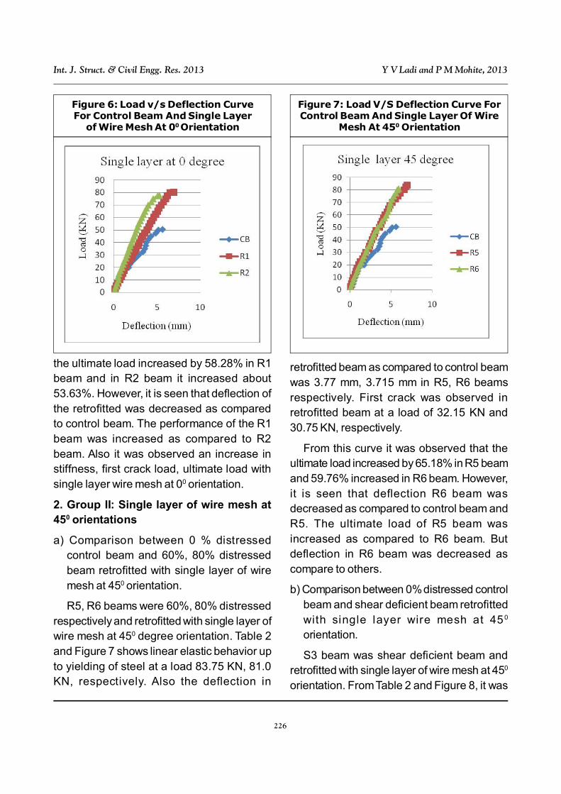
R1, R2 beams were 60%, 80% distressedrespectively and retrofitted with single layer ofwire mesh at 00 orientation. Control beamswere loaded under two point loading, the firstcrack was observed at a load of 19.0 KN.Control beam was failed at a load of 50.70KN and deflection at middle was 5.61 mm.Table 2 and Figure 6 shows linear elasticbehavior up to yielding of steel at a load 80.25KN, 77.75 KN in R1, R2 beams respectively.Deflection in retrofitted beam at load of 50.70KN was 4.02 mm, 2.61 mm in R1, R2 beams,respectively. First crack was observed inretrofi tted beam 29.5 KN, 29.0 KN,respectively. The failure of control andretrofitted beam was purely due to flexuralcracks. From this curve it was observed that
Table 2: Experimental results of all type of retrofitted beams with mode of failure
Beam type Beam First crack Ultimate Deflection Moment of
mark load (KN) load (KN) (mm) resistance (KN-m) Mode of failure
Control beam CB 19.00 50.70 5.61 7.605 Flexural failure
Flexural retrofitted R 1 29.5 80.25 6.89 12.0375 Flexural failure
Flexural retrofitted R2 29.0 77.75 5.25 11.66 Flexural failure
Flexural retrofitted R3 33.75 84.5 5.97 12.675 Flexural failure
Flexural retrofitted R4 32.0 80.50 5.12 12.075 Flexural failure
Flexural retrofitted R5 32.15 83.75 7.0 12.56 Flexural failure
Flexural retrofitted R6 30.75 81.00 5.935 12.15 Flexural failure
Flexural retrofitted R7 35.05 86.5 5.775 12.975 Flexural failure
Flexural retrofitted R8 34.75 82.75 5.14 12.4125 Flexural failure
Shear retrofitted S1 20.0 66.0 5.33 9.90 Flexural failure
Shear retrofitted S2 32.5 81.4 5.05 12.21 Flexural failure
Shear retrofitted S3 21.0 61.0 5.5 9.15 Flexural failure
226
Int. J. Struct. & Civil Engg. Res. 2013 Y V Ladi and P M Mohite, 2013
the ultimate load increased by 58.28% in R1beam and in R2 beam it increased about53.63%. However, it is seen that deflection ofthe retrofitted was decreased as comparedto control beam. The performance of the R1beam was increased as compared to R2beam. Also it was observed an increase instiffness, first crack load, ultimate load withsingle layer wire mesh at 00 orientation.
2. Group II: Single layer of wire mesh at450 orientations
a) Comparison between 0 % distressedcontrol beam and 60%, 80% distressedbeam retrofitted with single layer of wiremesh at 450 orientation.
R5, R6 beams were 60%, 80% distressedrespectively and retrofitted with single layer ofwire mesh at 450 degree orientation. Table 2and Figure 7 shows linear elastic behavior upto yielding of steel at a load 83.75 KN, 81.0KN, respectively. Also the deflection in
retrofitted beam as compared to control beamwas 3.77 mm, 3.715 mm in R5, R6 beamsrespectively. First crack was observed inretrofitted beam at a load of 32.15 KN and30.75 KN, respectively.
From this curve it was observed that theultimate load increased by 65.18% in R5 beamand 59.76% increased in R6 beam. However,it is seen that deflection R6 beam wasdecreased as compared to control beam andR5. The ultimate load of R5 beam wasincreased as compared to R6 beam. Butdeflection in R6 beam was decreased ascompare to others.
b) Comparison between 0% distressed controlbeam and shear deficient beam retrofittedwith single layer wire mesh at 450
orientation.
S3 beam was shear deficient beam andretrofitted with single layer of wire mesh at 450
orientation. From Table 2 and Figure 8, it was
Figure 6: Load v/s Deflection CurveFor Control Beam And Single Layer
of Wire Mesh At 00 Orientation
Figure 7: Load V/S Deflection Curve ForControl Beam And Single Layer Of Wire
Mesh At 450 Orientation

227
Int. J. Struct. & Civil Engg. Res. 2013 Y V Ladi and P M Mohite, 2013
observed that ultimate load of S3 beam was61.00 KN which is 20.31% of load incrementas compared to control beam. The first crackload was observed that at a load of 21.0 KNwhich is 10.52 % of load increment ascompared to control beam. In S3 beam firstcrack load was observed in the middle portionof the beam, it means that beam was failed inflexure. Also the deflection in retrofitted beam(S3) is minimum as compared to control beamwhich is 3.78 mm.
3. Group III: Double layer of wire mesh at00 orientations.
a) Comparison between 0% distressed controlbeam and 60%, 80% distressed beamretrofitted with double layer wire mesh at 00
orientation.
R3, R4 beams were 60% and 80%distressed beams retrofitted with double layerof wire mesh at 00 orientation. From Table 2and Figure 9, ultimate load in beam R3 and
R4 were 84.50 KN, 80.50 KN, respectively.Also the deflection in retrofitted beam at a50.70 KN load of 3.185 mm, 3.06 mm in R3,R4 beams, respectively. First crack wasobserved R3, R4 beams at a load of 33.75KN, 32.0 KN, respectively.
Load deflection behavior of the beamsevaluated by double layers of wire mesh at 00
plotted in Figure 9. From this curve it wasobserved that the ultimate load increased by66.66 % in R3 beam and 58.77% increasedin R4 beam. However, it is seen that deflectionof the retrofitted beam was decreased ascompared to control beam. The performanceof the 60% distressed beam in ultimate loadwas increased as compared to 80%distressed beam. Also it was observed anincrease in stiffness, first crack load, ultimateload with double layer wire mesh at 00
orientation.
b) Comparison between 0 % distressed
Figure 8: Load v/s Deflection Curve ForControl Beam And Shear Deficient Beam
Retrofitted With Single Layer Of WireMesh At 450 Orientation
Figure 9: Load v/s Deflection Curve ForControl Beam And Double Layer Of Wire
Mesh At 00 Orientation
228
Int. J. Struct. & Civil Engg. Res. 2013 Y V Ladi and P M Mohite, 2013
Figure 10: Load v/s Deflection Curve ForControl Beam And Shear Deficient Beam
Retrofitted With Double Layer Of WireMesh at 00 Orientation
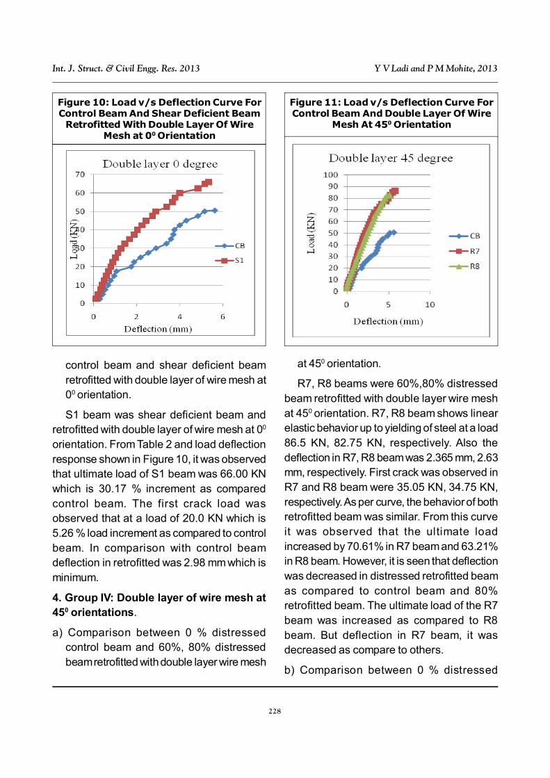
control beam and shear deficient beamretrofitted with double layer of wire mesh at00 orientation.
S1 beam was shear deficient beam andretrofitted with double layer of wire mesh at 00
orientation. From Table 2 and load deflectionresponse shown in Figure 10, it was observedthat ultimate load of S1 beam was 66.00 KNwhich is 30.17 % increment as comparedcontrol beam. The first crack load wasobserved that at a load of 20.0 KN which is5.26 % load increment as compared to controlbeam. In comparison with control beamdeflection in retrofitted was 2.98 mm which isminimum.
4. Group IV: Double layer of wire mesh at450 orientations.
a) Comparison between 0 % distressedcontrol beam and 60%, 80% distressedbeam retrofitted with double layer wire mesh
at 450 orientation.
R7, R8 beams were 60%,80% distressedbeam retrofitted with double layer wire meshat 450 orientation. R7, R8 beam shows linearelastic behavior up to yielding of steel at a load86.5 KN, 82.75 KN, respectively. Also thedeflection in R7, R8 beam was 2.365 mm, 2.63mm, respectively. First crack was observed inR7 and R8 beam were 35.05 KN, 34.75 KN,respectively. As per curve, the behavior of bothretrofitted beam was similar. From this curveit was observed that the ultimate loadincreased by 70.61% in R7 beam and 63.21%in R8 beam. However, it is seen that deflectionwas decreased in distressed retrofitted beamas compared to control beam and 80%retrofitted beam. The ultimate load of the R7beam was increased as compared to R8beam. But deflection in R7 beam, it wasdecreased as compare to others.
b) Comparison between 0 % distressed
Figure 11: Load v/s Deflection Curve ForControl Beam And Double Layer Of Wire
Mesh At 450 Orientation

229
Int. J. Struct. & Civil Engg. Res. 2013 Y V Ladi and P M Mohite, 2013
Figure 12: Load v/s Deflection Curve ForControl Beam And Shear Deficient Beam
Retrofitted With Double Layer Of WireMesh At 450 Orientation
control beam and shear deficient beamretrofitted with double layer wire mesh at 450
orientation.
To evaluate the performance of sheardeficient beam retrofitted with ferrocement, S2beam were retrofitted with double layer of wiremesh at 450 orientation. From Table 2 and loaddeflection response shown in Figure 12, it wasobserved that ultimate load of S2 beam was81.4 KN which is 60.55% load increment ascompared to control beam. The first crack loadwas observed that at a load of 32.5 KN whichis 71.05% load increment as compared tocontrol beam. First crack load was observedin the middle portion of the beam, it meansthat beam was failed in flexure. Also thedeflection in retrofitted beam was 2.6 mm
CB 0 0 19.0 0 50.70 0 116.92 0 7.605 0
R1 13.052 12.98 % 29.50 55.26 % 80.25 58.28 % 150.68 28.87 % 12.0375 58.28 %
R2 13.052 12.98 % 29.0 52.63 % 77.75 53.35 % 191.59 63.86 % 11.66 53.32 %
R3 26.104 25.96 % 33.75 77.63 % 84.50 66.66 % 183.11 56.61 % 12.675 66.66 %
R4 26.104 25.96 % 32.0 68.42 % 80.50 58.77 % 203.41 73.97 % 12.075 58.77 %
R5 17.068 16.97 % 32.15 69.21 % 83.75 65.18 % 154.78 32.38 % 12.56 65.15 %
R6 17.068 16.97 % 30.05 61.84 % 81.00 59.76 % 176.56 51.00 % 12.15 59.76 %
R7 34.136 33.95 % 35.05 84.47 % 86.50 70.61 % 193.782 65.73 % 12.975 70.61 %
R8 34.136 33.95 % 34.75 82.89 % 82.75 63.21 % 208.28 78.52 % 12.41 63.18 %
S1 26.104 25.96 % 20.0 5.76 % 66.00 30.17 % 160.201 37.01 % 9.90 30.17 %
S2 34.136 33.95 % 32.5 71.05 % 81.40 60.55 % 208.53 78.35 % 12.21 60.55 %
S3 17.068 16.97 % 21.0 10.52 % 61.00 20.31 % 156.27 33.65 % 9.15 20.31 %
Table 3: Comparative Results Of Control Beam And Retrofitted Beam
Be
am
Are
a o
fw
ire
me
sh
(mm
2)
% o
f ste
el
inc
rem
en
t
Fir
st
cra
ck
loa
d (k
N)
% o
f lo
ad
inc
rem
en
t
Ult
ima
telo
ad
(kN
)
% o
f lo
ad
inc
rem
en
t
Fle
xu
ral
rig
idit
yk
N.m
2
% o
fin
cre
me
nt
Mo
me
nt
of
res
ista
nc
e(k
N. m
)
% o
fin
cre
me
nt

230
Int. J. Struct. & Civil Engg. Res. 2013 Y V Ladi and P M Mohite, 2013
which is minimum as compared to controlbeam Following Table 3 shows the percentageincrement of ultimate load, first crack load,moment of resistance, flexural rigidity.
2/where64823
3
WPEI
PLDeflection
CONCLUSIONThe conclusions drawn from the resultsobtained in this study are as follows:
1. All the beams retrofitted with ferrocementin single layer and two layers of wire meshat various orientations experience flexuralfailures. None of the beams exhibitpremature brittle failure or shear failure.
2. Ferrocement properly bonded to threesides of RC beams can enhance the flexuralstrength substantially. The flexural retrofittedbeams exhibit an increase in flexuralstrength of 60 to 66% for single layer at 450
orientation and 64 to 71% for two layers at450 orientations.
3. In shear retrofitting, it exhibit an increase inshear strength of 66.55% for double layerof wire mesh at 450 orientation and 30.17to 20.31% increase in shear strength for twolayers of wire mesh at 00 and single layer ofwire mesh at 450, respectively.
4. The flexural retrofitted beams enhance firstcrack load is about 83 to 85%. In shearretrofitting it increases about 71%.
5. At any given load level, the stiffness areincreased signi ficantly because ofdecreasing deflection of the retrofittedbeams because of an increasingpercentage of steel. At ultimate load levelof the control specimens, the retrofitted
beams exhibit a decrease of deflection upto 60%.
6. After retrofitting, all the test specimensobserved reduced crack widths, deflectionand spacing of cracks at the ultimate load.
7. In flexural retrofitted beam 80% distressedbeam exhibits about 70% increment inflexural rigidity. In shear strengthening itincreases in between 31 to 70%
8. The beams retrofitted with ferrocement atdifferent orientations do not de-bond whenloaded to failure.
REFERENCES1. Ganeshan N and Thatathil S P (2005),
“Rehabilitation of Reinforced ConcreteFlexural Elements using FerrocementJacketing”, Journal of StructuralEngineering, Vol. 31, No. 4.
2. Paramasivam P, Lim C T E and Ong K CG (1998), ”Strengthening of RC Beamswith Ferrocement Laminates”, Cementand Concrete Composites, Vol. 20, pp.53-65.
3. Patil S S, Ogale R A and Dwivedi A K(2012), “Performances of Chicken Meshon Strength of Beams Retrofitted UsingFerrocement Jackets”, Journal ofEngineering, Vol. 2, pp. 1-10.
4. Rafeeqi S F A and Ayub T (2011),“Investigation of Versatil ity of theTheoretical Prediction Models for PlainConcrete Confined with Ferrocement”,Asian Journal of Civil Engineering, Vol.12, No. 3, pp. 337-352.
5. Reddy M V (2011), “Retrofitting of ShearDeficient RC Beams using Ferrocement

231
Int. J. Struct. & Civil Engg. Res. 2013 Y V Ladi and P M Mohite, 2013
Jacketing”, Journal of Institute ofEngineers (India), Vol. 92, pp. 42-48.
6. Sheela S and Anugeetha B (2009),“Study on the Performance of Reinforced
Concrete Beam Retrofitted usingFerrocement and GFRP”, 10th NationalConference on Technological Trends, pp.6-7.