experimental and numerical assessment of a new … and numerical assessment of a new... · new...
TRANSCRIPT
Experimental and Numerical Assessment of a New Alternative of RBS Moment Connection
Rasoul Mirghaderi^, All Imanpour^ ,Shahab Torabian^ ,Farhad Keshavarzi^
Assistant Professor, Civil Engineering Department, Tehran University, Tehran, Iran
Graduate Student, Civil Engineering Department, Tehran University, Tehran, Iran
PhD Candidate, Civil Engineering Department, Tehran University, Tehran, Iran
Abstract. Reduced beam section (RBS) connection has been known as a famous connection for steel moment-resisting seismic frames in high-rise buildings, because of their economical advantages and seismic ductility. In the ordinary RBS connection, often portions of the beam flanges are selectively trimmed in the region adjacent to the beam-to-column connection, and beam section is weakened in the plastic hinge region; section weakening concept in the plastic hinge region of beam cause to reduction of beam plastic section modulus in this region, and force plastic hinge to occur within the reduced section.
This paper presents a new alternative of RBS connection that has been used aforesaid weakening concept in it, with this difference that corrugated steel plate webs instead of beam flange cutting has been used in limited specific length near the column face. Corrugated steel plates because of their accordion effect don't have bending rigidity, then using of these plates in plastic hinge region reduces the beam plastic section modulus and plastic hinge is formed in corrugated region. For investigating the seismic behavior and performance of new RBS moment connection, experimental specimen of new RBS connection were subjected to cyclic load, and finite element analysis were executed. The result of cyclic test and numerical analysis specified that the corrugated webs improved the plastic stability and provided capability of large plastic rotation at the plastic hinge location without any appreciable buckling and brittle fractures in this region. The test observations also showed that the specimens' plastic rotations exceeded 0.04 rad without any local and global buckling. All of the analytical results for proposed connection are generally in good agreement with the test observations.
Key words: Reduced beam section connection, plastic hinge, corrugated steel plates, finite element analysis.
INTRODUCTION
Numerous occurrences of brittle fractures in the welded beam-to-colunin connections of steel moment-resisting frames after the 1994 Northridge (CaHfomia) and 1995 Hyogo-ken Nanbu (Japan) earthquakes demonstrated that the steel structure design concepts and detailing have quandaries. Most of these fractures were observed in the vicinity of the beam flange to the column welds even prior to yielding of the beam plastic hinge. Sac Joint venture and American Institute of Steel Construction (AISC) conducted extensive researches [1, 2]; their conclusions confirm lack of suitable detailing and some other defects in steel moment connections. Some of the observed defects include weld defects, stress concentration near the weld, low
CP1020, 2008 Seismic Engineering Conference Commemorating ttie 1908 l\^essina and Reggio Calabria Earttiquai<e, edited by A. Santini and N. Moraci
© 2008 American Institute of Physics 978-0-7354-0542-4/08/$23.00
1024

thickness of the column flange, high yield to tensile strength ratio in the beams materials, and presence of residual stresses due to weld shrinkage [3].
Numerous changes were made in the concepts and methods of design and detailing of steel structure moment connections after Northridge earthquake. One of the important and fundamental parts of these changes was making particular details in moment-resisting connections to enhance ductility and the seismic energy dissipation potential with least value of strength reduction. Design method of beam-to-column moment connections, which are the most sensitive components of the steel moment-resisting frames, were basically altered. Most of the changes concerned the correction of existing methods, creating new methods for detailing of steel moment-resisting connections and solving the aforesaid defects about these connections. The philosophy of all the methods was based on the fact which reduces the stress level in the beam flange weld and force plastic hinge in the beam, away from the column face.
The methods presented in standards, codes and researches about the steel moment-resisting connection detailing can be categorized in two general groups. The first group includes the reinforced connection such as addition of a haunch or cover-plate near the column face. The second group includes connections that beam section is intentionally weakened in the plastic hinge region which is known as RBS connections.
RBS CONNECTIONS
Special steel moment-resisting frame systems are among the most common lateral load carrying systems, which are selected by engineers as the first priority, due to their advantages in design, detailing, fabrication and operation. Beams as the source of providing the ductility of the steel moment-resisting frames, dissipate the seismic energy and provide the lateral load carrying of structure by their stable inelastic behavior. The ductile zone of the beams is the formed plastic hinge in two end of the beam which is the most fundamental energy dissipation source in such systems. Then detailing of the beam-to-column connection, play a key role in the plastic hinge formation in the beams.
Changes in detailing methods of steel moment-resisting connections after Northridge earthquake (1994) and the presentation of new design methods for steel structure connections cause to improve the seismic performance of steel structures with moment-resisting frame systems. Utilization of the reduce beam section "RBS" moment connection in steel moment-resisting frames was one of the procedures adopted after Northridge earthquake and most researches were accomplished efficient works to improve the seismic behavior and present the design procedure for this connection. The RBS connection can be used in new or in existing moment-resisting framed buildings [3].
Quasi-static loading tests performed on full-scale specimens by Chen in 1994 confirmed the ability of RBS connection to sustain large inelastic rotations. These tests also indicated that trimming the beam flanges at the plastic hinge location has very limited impact on the stiffness of the beam and consequently on the stiffness of frame, the lateral stiffness of the structure are not reduced perceptibly by using of beams with RBS connection in structure stories. Although reduction of the lateral stiffness of structure is not tangible in regard to most of the researches which has been accomplished on moment-resisting frames with RBS connection, but the lateral stiffness reduction can increase story drift of structure [4]. Studies were accomplished
1025
by Shen et al in 1999 on steel moment-resisting frame with RBS connection demonstrated that the beam section weakening through plastic hinge region, have shght effect on inelastic drift response, for example the inelastic drift ratio response does not increase considerably (less than5%) in the frames with moderate reduction in the RBS (up to 40% flange reduction) [5]. With regard to researches based on seismic evaluation and cyclic response of RBS connection, some of the advantages of using this connection in steel moment-resisting frames are as follows: 1. Compared to reinforced connections, RBS connections use leads to reduced demands for continuity plates, panel zone reinforcement, and strong column-weak-beam requirements [6]. 2. RBS connections are more efficient and economical, because they do not require the extra field welding and material associated with reinforced connections [6]. 3. The results of the analyses indicated that RBS connections can achieve the target beam plastic rotation at lower strain demands than comparable traditional connections [7]. 4. RBS connection could develop uniform plastic strains in the reduced beam flange region. Also the reduced beam section was able to alleviate strain concentrations in the critical connection region compared to non-RBS connection [6]. 5. In the RBS connection, plasticization and plastic strain zone are inside the beam, and do not enter the connection zone. Also reduced section is so near the column face that cause the least moment demands transfer to the beam end and eventually to the column [8].
Considering the advantages of using the RBS connection in steel moment-resisting frames, performing the numerous researches on RBS connection and testing of different experimental RBS connection, this connection is highly recommend in high seismic risk zones because of economic aspect and providing the requirement of a steel moment-resisting connection.
DESIGN RECOMMENDATIONS FOR RBS CONNECTIONS
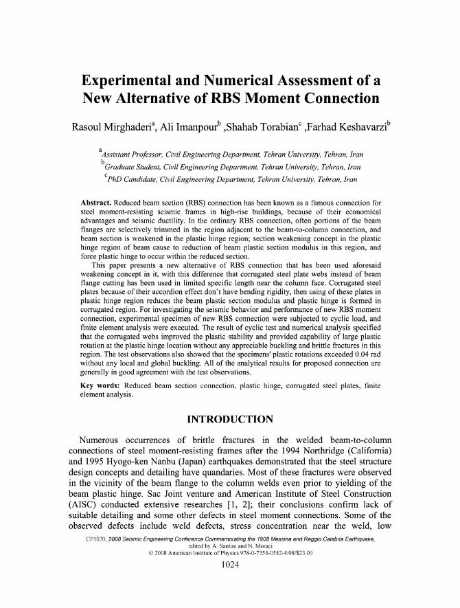
Numerous advantages of RBS connection and improving the design, construction and installation techniques of steel structures have been led to attract the attention of engineers to use such connections in steel moment-resisting frame structures; Hence there is a need to set the recommendations and design criteria for RBS connection. Various standards and codes have been presented some design recommendations for design of common RBS connection for instance those offered by American Institute of Steel Construction (AISC) and FEMA recommendations [9, 10]. AISC and FEMA have presented recommendations to design of the RBS connection which beam flange width was trimmed in the plastic hinge region (dog bone connection); three kinds of common RBS connection (tapered cut, radius cut, and straight cut) are shown in FIGURE 1. Most of the recommendations in FEMA 350 have since found their way into the Prequalified Connections for Special and Intermediate Steel Moment Frames for Seismic Applications (AISC) [9]. The philosophy behind the AISC connection provisions, which is similar to the FEMA 350 philosophy, is to provide an adequate combination of connection stiffness, strength, and ductility to ensure acceptable seismic performance.
1026
<^)n
( b )
(c)
C7~
FIGURE 1. Various common RBS configurations: (a) tapered cut, (b) radius cut, and (c) straight cut.
Recommended seismic design criteria for common RBS (dog-bone) connections by AISC and FEMA 350 include geometrical equations to determine the position and length of the reduced section in the beam and the beam flange trimming procedure in the reduced section zone as well as the column and beam limitations in RBS connection. Although design procedure for RBS connection by such relationships provide the requirements of a beam-to-column moment connection in the moment-resisting frame, but they can not be a general design procedure for all of RBS connections reduced in the plastic hinge region. They are particularly utiHzed for design of RBS connection that the beam flange width decreases in the theorical plastic hinge region of this connection.
In addition to RBS connection configurations which were shown in FIGURE 1, and detailing specified by AISC and FEMA 350, various detailing for RBS connection have been proposed by different researchers with using of reducing beam section in the plastic hinge region concept; and there are not any compiled design procedures for most of these detailing in the codes yet. The only RBS connection with reduced flange (dog bone connection) has organized design criteria. Some of the recommended details as a RBS connection are as follows [10, 11]: 1. The reduction of the beam depth in the plastic hinge region. 2. Drilling the beam web in the plastic hinge region. 3. Drilling the beam flange in the plastic hinge region.
Although the aforementioned detailing has relative advantages with regard to common RBS connection, but they have some particular defects and problems which are global and fundamental in some cases. This is led to common RBS connection was preferable in the current condition and practical cases.
A PROPOSED FOR A NEW RBS CONNECTION DETAIL
The beams with RBS connection are reduced in the plastic hinge region; this reduction causes the dwindling of the plastic section module of reduced section and diminishes the seismic demand exerted on the connection. In the common RBS connection, reduction of the section plastic modules is performed through the weakening of the flanges in the
1027

regions where plastic hinge are formed and the beam web is retained unchanged in the reduced section; but they have local problems such as lateral-torsional buckling, local buckling of web and flange in the plastic hinge region, formation of fragile cracks before yielding in the section and intricacy of detailing in order to avoiding the stress concentration effects and etc [8]. On the other hand, whereas beam web because of linear variations of stress in the beam height, is yielded later than flanges and delay the complete yield of the section; thus if the web does not have a role in the bending capacity, without any modifications in the shear strength, we can run to a beam with appropriate reduced special zone with regard to common RBS connection [12].
The utilization of the corrugated plates in the beam web within the plastic hinge region is a manner of fulfilling the formation of such reduced sections. The idea of utilizing corrugated plates has been often implemented in bridges to preclude the lateral buddings of beams and no vertical web stiffeners are used, up to now. Using the corrugated plates in beam web, because of their accordion shape, causes the web not to have a role in sustaining the axial stresses due to bending in the plastic hinge zone [13]; Hence, flanges will have to sustain the bending stresses on their own. In this manner, we achieve a reduced section in the plastic hinge zone of the special steel moment-resisting fi-ame beams where only flanges sustain the bending stress and web tolerate the shear stress. FIGURE 2 shows the new RBS connection that the corrugated plates have been placed in beam reduced section within plastic hinge region.
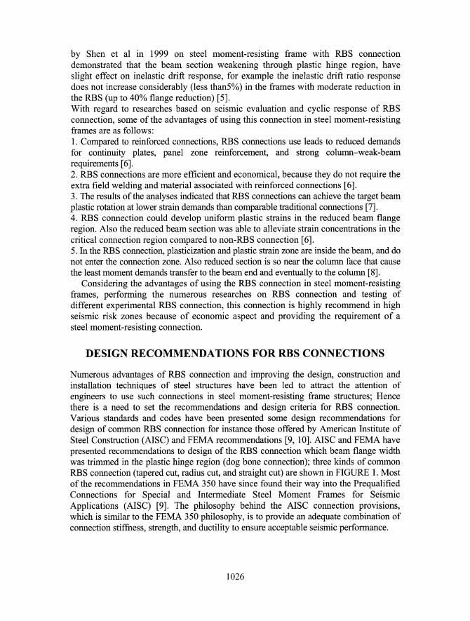
FIGURE 2. New RBS comiection during fabrication process
NEW RBS DETAILS AND DESIGN STEPS
The design of the welded new RBS moment connection was based on the Prequalified Connections for Special and Intermediate Steel Moment Frames for Seismic AppUcations (AISC) and FEMA 350 [9, 10], and the design of the RBS regions was modified from a procedure recommended by Mirghaderi in 1997 [14] for new reduced beam section moment connection with corrugated web in beam plastic hinge zone. An overall view of the test setup is shown in FIGURE 3.
The details of the moment connection for new RBS connection specimen are shown in FIGURE 4. The column section was a box section (200 x 160 x 10 mm) and the beam was an IPE180 section. The continuity plates inside the column matched the inner column dimensions, thickness of continuity plates were 15 mm. Thickness of the column web
1028

increased to 15 mm in the panel zone distance. The length of each side of the corrugated plate section, placed in the plastic hinge zone, was 50 mm and their thicknesses were 3 mm.
FIGURE 3. Test setup
To^^^^^
,15 mm Continuity Plate
FIGURE 4. New RBS specimen moment connection detail
TEST SPECIMEN AND EXPERIMENTATION
Construction and Inspection
Three plates of the column were connected with fillet weld, and a U shape was made; then continuity plates were inserted in their positions inside the column. Back plates were installed beneath the groove welded point of continuity plates. For continuity plates groove weld, E70 electrodes were used. Then fourth side of the box column was installed, for the all fillet welds of the box column E60 electrodes were used. The beam webs were cut and smoothed in the considered length for installing the corrugated plates. Corrugated plates were inserted in the holed length of the beam web, and connected to the beam web and flanges by fillet weld. Finally the beams installed on both sides of the box column. All the welds were accomplished in the shop by a commercial fabricator. All groove welding was subject to ultrasonic testing by a licensed inspector.
1029
Material Properties
The materials utilized to fabricate the experimental specimen were mild steel (Grade 37). Yield strength for column plates is 253 Mpa, for beam is 316 Mpa, and for corrugated plates is 406 Mpa.
Test Setup
Test specimen was mounted to the strong floor (FIGURE 2.). Test specimen as a connection from internal joint of a moment-resisting frame was chosen [15]. In the equivalent subassembly, inflection point of beams and columns were in the middle length of them, when earthquake loading was exerted to this frame; for simulation of subassembly boundary conditions, the column was supported at the base by a hinge and beams are rolled at the end. The beam was laterally braced at the plastic hinge location and a distance from the first lateral support. This distance coincides with AISC seismic provisions [15]; also the lateral support of the column was placed in the top of the connection joint.
Loading History
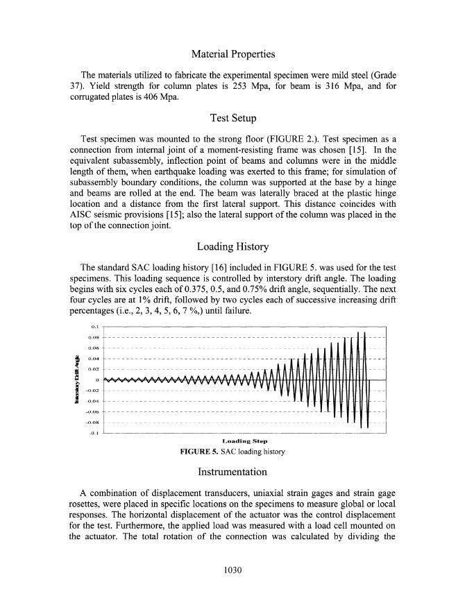
The standard SAC loading history [16] included in FIGURE 5. was used for the test specimens. This loading sequence is controlled by interstory drift angle. The loading begins with six cycles each of 0.375, 0.5, and 0.75% drift angle, sequentially. The next four cycles are at 1% drift, followed by two cycles each of successive increasing drift percentages (i.e., 2, 3, 4, 5, 6, 7 %,) until failure.
Loading Step
FIGURE 5. SAC loading history
Instrumentation
A combination of displacement transducers, uniaxial strain gages and strain gage rosettes, were placed in specific locations on the specimens to measure global or local responses. The horizontal displacement of the actuator was the control displacement for the test. Furthermore, the applied load was measured with a load cell mounted on the actuator. The total rotation of the connection was calculated by dividing the
1030

column tip displacement by the length from the tip of the column to the column base hinge.
TEST OBSERVATION OF SPECIMEN
Very minor flaking of the whitewash was noticed at the end of the cycles of 1.5% drift on the beam flange in the RBS region (in the center of the corrugated box), this event show that the value of strain increase to plastic strain in the RBS region. During the cycles of 3% and 4% drift the flaking of the whitewash began to extend to the two side of RBS region in the beam flange. During the cycles of 5% and 6% drift, approximately all of the whitewash of the beam flange width in the RBS region flaked, and at the end of the cycles of 6% drift panel zone was yielded. By 7% drift the lateral-torsional buckling of one of the beams, and beam flange local buckling was observed simultaneously; these bucklings led to small drop in the exerted force. Also in this cycle very minor flaking of the corrugated plates whitewash was noticed; FIGURE 6, show the connection region and the RBS region of specimen at the end of 7% drift. At the end of the cycle of 8% drift, flaking of the whitewash extended to outside of the RBS region. During the cycle of 9% drift small cracks formed in fillet weld of corrugated plates to the beam flange connection, and finally at the end of this cycle two number of corrugated plates fractured at the center of the RBS region.
(a) (b) FIGURE 6. (a) Connection region after 7% story drift cycles, (b) Beam flange within RBS region after
7% story drift cycles
ANALYTICAL STUDY
A model of connection was created and analyzed using the finite-element analysis program ABAQUS. The program is capable of conducting a large-deformation nonlinear (including material and geometric nonhnearities) three-dimensional analysis. Four-node general shell elements were used with a five Gauss point across the thickness.
1031

To facilitate the geometric modeling, the longitudinal and inclined folds were assumed to intersect without a transition region. None of the specimen welds were modeled. A sample of the meshing model of the new RBS connection at the connection joint is illustrated in FIGURE 7(a). Material with a Young's modulus of 200,000 MPa and a Poisson's ratio of 0.3 was assigned. The yield strength of the material was based on the material properties. For the nonlinear inelastic analysis, a kinematic hardening stress versus strain curve was used in the model. The von mises yield criterion with associated flow rule was used to model the elasto-plastic behavior of the steel. The column tip was loaded monotonically by imposing a displacement. The modified Riks method was used for the analysis because the expected strength degradation due to excessive buckling would cause the standard Newton method to diverge numerically.
Li the analytical model, those portions of the beam flange in the reduced area behaved like the experimental specimen and accepted nonlinear deformations. As was predicted and depicted in the experimental specimen, nonlinear deformations occurred mostly in the beam weakened region (beam flange through RBS region) where the corrugated plates aplaced; and they propagated so slightly towards the column face and the beam flange groove weld which are highly sensitive towards brittle fi*actures. This fact is shown in FIGURE 7(b).
(a) (b) FIGURE 7. (a) Finite element model of specimen, (b) Plastic strain contour of beam flange within RBS
region at 7% story drift
CONCLUSION
1. The experimental observations which was resulted during cyclic loading test on the RBS moment connection with the corrugated web in the plastic hinge region, demonstrated that the proposed connection satisfy the requirements of a beam-to-column moment connection in special steel moment-resisting seismic frame with regard to AISC seismic provision [11]; and it can be utilized as a moment connection in special steel moment-resisting frames in high seismic risk zones. 2. The finite element analysis results for proposed connection are generally in good agreement with the test observations. In addition that the numerical modeling of this connection is verified by means of the finite element method, ABAQUS finite element software is a suitable program to monitor the seismic behavior of the new RBS connection.
1032
3. The analytical and experimental results show that the proposed connection has an acceptable capability of the seismic energy dissipation as a RBS connection. Also the nonlinear deformations occur mostly within the theoretical predicted plastic hinge region, and the proposed connection plastic rotations exceeded 0.04 rad without any local and global buckling. 4. The corrugated webs improve the plastic stability and provide capability of large plastic rotation at the plastic hinge location of the specimen without any appreciable local and global buckling and brittle fractures in this region up to 7% story drift. 5. New RBS connection contrary to the typical RBS connection and the other proposed RBS connections was fabricated easily and its fabrication process is not sensitive to high accurate cutting and continuous control.
REFERENCES
1. American Institute of Steel Construction (AISC), Northridge steel update I, Chicago, American Institute of Steel Construction, October 1994.
2. SAC Joint Venture, Interim guidelines: evaluation, repair, modification and design of steel moment frames Report No. SAC-95-02, Sacramento, Cahf, SAC Joint Venture, 1995.
3. R. Tremblay and A. Filiatrault, "Seismic performance of steel moment resisting frames retrofitted with a locally reduced beam section connection". Journal of Civil Engineering, Vol.24, 1997, pp.78-89.
4. S.-J. Chen, and C.H. Yeh„ "Enhancement of ductility of steel beam-to-column connections for seismic resistance". Proceedings of the 1994 Structural Stability Research Council Annual Technical Session, Chicago, 111., 1994, pp. 327.338.
5. J. Shen , T. Kitjasateanphun and W. Srivanich, "Seismic performance of steel moment frames with reduced beam sections", Engineering Structure, Vol.22, 2000, pp.968-983.
6. J. Jin, S. El-Tawil, "Seismic performance of steel frames with reduced beam section connections", Journal of Constructional Steel Research, Vol 61, 2005, pp.453-471.
7. S. L. Jones, G. T. Fry and M. D. Engelhardt, "Experimental Evaluation of Cyclically Loaded Reduced Beam Section Moment Connections", Journal of Structural Engineering, Vol. 128, 2001, pp. 441-451.
8. N. Iwankiw, "Seismic Design Enhancements and the Reduced Beam Section Detail for Steel Moment Frames", Practice Periodical on Structural Design and Construction, Vol.9, 2004, pp.87-92.
9. American Institute of steel construction. Inc. (AISC), Prequalified Connections for Special and Intermediate Steel Moment Frames for Seismic Applications, Chicago. IL., AISC, 2005.
10. FEMA 350. Recommended Seismic Design Criteria for New Steel Moment-Frame Buildings, Washington. DC, prepared by the SAC joint venture for the Federal Emergency Management Agency, 2000.
11. S. Wilkinson, G. Hurdman and A. Crowther, "A moment resisting connection for earthquake resistant structures". Journal of Constructional Steel Research, Vol. 62, 2006, pp.295-302.
12. M. Elgaaly, , D. Smith, and R. Hamilton, "Beams and girders with corrugated webs", Proc. 1992 NSF Structure Geomechanics and Building systems Grantees, Conference college of Engineering, Univ. of Puerto Rico. Mayaguez, Puerto Rico, 1992, pp. 126-128.
13. L. Huang, H. Hikosaka, and K. Komine, "Simulation of accordion effect in corrugated steel web with concrete flanges". Computers & Structures Vol. 82, 2004, pp. 2061-2069.
14. R. Mirghaderi, A. Imanpour, F. Keshavarzi, and B. Khafaf, "Seismic Design Procedure and Detailing of New Reduced Beam Section Moment Connection with Corrugated Web in Beam Plastic Hinge Zone", International Earthquake Symposium Kocaeli 2007, Kocaeli, 24-26 October 2007.
15. American Institute of steel construction. Inc. (AISC), Seismic Provision for Structural Steel Buildings, Chicago. IL., AISC, 2005.
16. P. Clark, K. Frank, H. Krawinkler, and R. Shaw, Protocol for fabrication, inspection, testing, and documentation of beam-column connection tests and other experimental specimens Rep. No. SAC/BD-97/02, Sacramento, Cahf., SAC Joint Venture, 1997.
1033