experimental and analytical studies of fixed-base and
TRANSCRIPT

Experimental and Analytical Studies of Fixed-Base and Seismically Isolated
Liquid Storage Tanks
Vladimir Calugaru Stephen A. Mahin
October 16, 2009
Department of Civil and Environmental Engineering
University of California, Berkeley

Acknowledgements
This project was made possible by a grant from PEER and a gift from Earthquake Protection Systems, Inc.

Presentation Outline
Tank Design and Research Background
Project Goals
Experimental Program
Experiment Results
Model Validation
Summary and Conclusions

Tank Research Background G.W. Housner (Caltech) – 1957, 1963
R.W. Clough & students (Berkeley) - 1970s
A.S. Veletsos (Rice) – 1977, 1984
M.A. Haroun (UC Irvine) – 1981
M.S. Chalhoub & J.M. Kelly (Berkeley) – 1988
Y.P. Wang et.al (Taiwan) - 2001
M.K. Shrimali & R.S. Jangid (India) – 2002
V.P. Gregoriou et. al (Greece) – 2005
I.P. Christovasilis et. Al (Buffalo, NY) – 2008

Tank Design Background Based on Rigid Tank Model (Housner, 1963)
- ACI 350.3
- AWWA D-100
- AWWA D-110
- API 650
Based on Flexible Tank Models (Veletsos, Yang, 1977) and (Haroun, Housner, 1981)
- NZSEE
- Eurocode 8

Project Goals
Perform single and multi-component shaking table tests on fixed-base and seismically isolated tank
Compare base shear, water sloshing, and tank deformation response for parameters of interest
Validate numerical mechanical analog tank model
Compare water sloshing dynamics for 1-, 2-, and 3- component ground motions

Experimental Program Vertical Cylindrical Open-Top Steel Tank
- 6ft dia. x 6ft tall
- ¼ inch wall and base
- Unanchored
Seismic Isolators
- Friction Coefficients [µ1, µ2, µ3] = [0.05, 0.11, 0.11]
- T1 = 0.72sec
- T2 = 2.03sec
- T3 = 2.79sec
empty 18in 36in 54in
Total Weight (kips)
40.58 43.29 46.00 48.71
T1 (sec) x 1.66 1.45 1.42 T2 (sec) x 0.83 0.83 0.83 T3 (sec) x 0.66 0.66 0.66

Experimental Program Ground Motions
- Loma Prieta (California, 1989)
- Kobe (Japan, 1995)
- Chi-Chi (Taiwan, 1999)
Length Scales 1/5 to 1/2
Magnitude Scales 1/4 to 1
Water Levels H/R = 0 (empty) to 1.5 (54in)
Isolated vs. Fixed Base
Total of 264 tests conducted

Experimental Program
L4 L2 L3 L5 L1
Different ground motions expected to cause higher water sloshing at different test length scales

Test Setup Construction
Complete Test Setup

Test Setup Construction
The steel frame, isolators, and load cells are carefully assembled in an upside-down position to ensure symmetric and level support.

Test Setup Construction
The supporting structure is flipped and brought to the shaking table using the laboratory crane. The 1-¼”dia. steel rods penetrate table's concrete slab.

Test Setup Construction
Underneath the shaking table a compressed air gun is used to secure the supporting structure to the table.

Test Setup Construction
17kip concrete blocks are positioned on top of the support. 1-¼”dia. steel rods that will be used to tie the concrete blocks to
the steel frame are awaiting their call to duty.

Test Setup Construction
The setup is almost ready for the bearing characterization tests. The restraining steel braces and two middle concrete blocks will be removed for the tank tests.
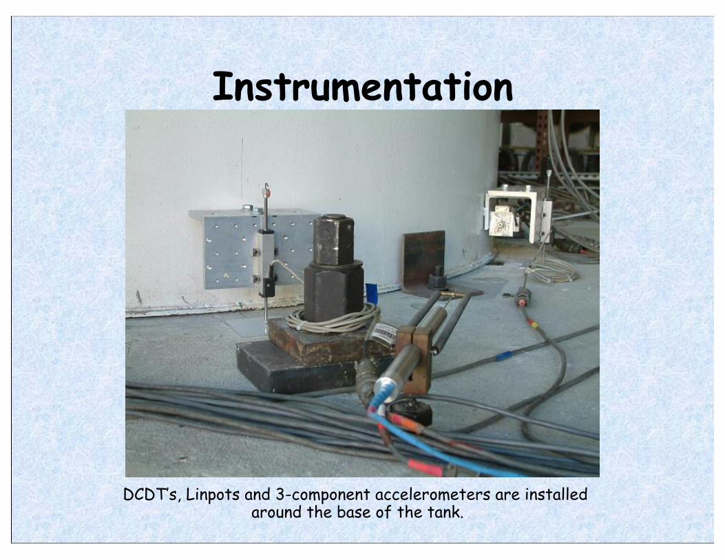
Instrumentation
DCDT’s, Linpots and 3-component accelerometers are installed around the base of the tank.

Instrumentation
DCDT’s, water depth gauges, and 2-component accelerometers are installed around the top rim of the tank.

Parallel Wire Water Depth Gauge Schematic Representation
The Pwire gauge works as a strain gauge – an imbalance in the Wheatstone bridge is calibrated to change in water depth

Parallel Wire Water Depth Gauge Calibration
Near-linear Pwire behavior over ±20in range

Complete Test Setup
A total of 264 shaking table tests were conducted.

Experiment Results Base Shear
Reduction in base shear by a factor of 5 to 10, and constant for a wide range of H/R ratios
These results are for length scale 1/4 and magnitude scale 1/2 tests.

Experiment Results Tank Uplift
Reduction in tank uplift by up to an order of magnitude.
These results are for length scale 1/4 and magnitude scale 1/2 tests.

Experiment Results Tank Deformation
Reduction in tank deformation by up to an order of magnitude.
These results are for length scale 1/4 and magnitude scale 1/2 tests.

Experiment Results Water Sloshing Height
Water sloshing does not show as clear patterns as other response quantities
These results are for length scale 1/4 and magnitude scale 1/2 tests.

Experiment Results Water Sloshing Height: FFT Study
Contribution of symmetric sloshing modes is evident. Seismic isolation effectively reduces 1st mode sloshing.

Experiment Results Acceleration Amplification
Seismic isolation effectively limits acceleration amplification in the supporting structure and liquid storage tank

Model Validation Base Shear
Significant acceleration amplification between table top and steel frame due to some rocking and bolt slip is a bummer.

Model Validation Water Sloshing Height
Code-based estimate for maximum sloshing in fixed-base tank – not bad for isolated tank. Housner model spring oscillation matches test sloshing during excitation.

Project Conclusions • Seismic isolation is effective in reducing base shear, tank
deformation, and tank uplift
• A simple 1-dof Housner model provides a good estimate of base shear for both fixed-base and isolated liquid storage tanks
• Higher sloshing modes important for sloshing dynamics, not for base shear and tank stresses
• SRSS combination of individual 1D simulation responses provides a good estimate of 2D excitation response
• Code provisions for maximum sloshing for fixed-base tanks also valid for isolated tanks
• 2- and 3- component ground motions significantly affect tank uplift and liquid sloshing dynamics

Thank you!

The Following Slides Contain Additional Information Available
upon Request

Instrumentation

Instrumentation
Instruments used in the experiment

Edge Detection to Measure Water Surface Dynamics
Split video into individual frames. Apply the ED algorithm to each frame to...
(1) (2)
...obtain a matrix of mostly zeros (black), and a few ones (white) representing the water surface edge. Calibrate pixels to inches.
(3a) (3b) (3c)

Model Validation Predicting Water Sloshing Dynamics
Code-based estimate for maximum sloshing in fixed-base tank – not bad for isolated tank

Future Work
• More work on edge-detection approach
• Finite element model to compare with mechanical analog models and test data
• Fit tank uplift and deformation test data to existing models
• Interaction of water sloshing with shaking table