experience with synchronous and asynchronous digital ...€¦ · and disadvantages. for synchronous...
TRANSCRIPT

NASA-TM-88271
NASA Technical Memorandum 88271 /1F6tJ2J~D:311
Experience With Synchronous and Asynchronous Digital Conltrol Systems Victoriia A. I~egenie, Claude V. Chacon, and Wilton P. Lock
August 1986
ruM;1\ National Aeronautics and Space Administration
LIBRARY COpy
FEB 2 2 3lO6
NASA LANGLEY RESEARCH CENTER HAMPTON, VA
1111111111111 1111 11111 11111111111111111111111 NF00965
https://ntrs.nasa.gov/search.jsp?R=19860020394 2020-04-26T17:35:12+00:00Z

· \\\\~'\'\I~~~lnl\\\\~\\\\1 3 117601497 1932
NASA Tc~chnical Memorandum 88271
EXI~erience With Synchronous and Asynchronous Digital Control Systems Victoria A. Regenie, Claude V. Chacon, and Wilton P. Lock Ames RElsearch Clmter, Dryden Flight Research Facility, Edwards, California
1986
NI\S/\ National Aeronautics and Space Aclministration Ames Re:search Center Dryden Flight Research Facility Edwards, California 93523·5000

EXPERIENCE WITH SYNCHRONOUS AND ASYNCHRONOUS DIGITAL CONTROL SYSTEMS
Victoria A. Regenie,* Claude V. Chacon,** and Wilton P. Lock**
NASA Ames Research Center Dryden F"' i ght Research Facil ity
Edwards, California
Abstract
Fl ight control systems have undergone a revo' ut i on s i nc:e the days of s ; mp 1 e mechani ca 1 linkages; presently the most advanced systems are full-authority, full~time digital systems controlling unstable aircraft. With the use of advanced control systems, the aerodynami c design can incorporate features that allow greater performance and fuel savings, as can be seen on the new Airbus design and advanced tactical fighter concepts. These advanced aircraft will be and are relying on the flight control system to provide the stability and handling qualities required for safe flight and to allow the pilot to control the aircraft. Various design philosophies have been proposed and followed to investigate system architectur'es for these advanced flight control systems. One major area of discussion is whether a multichannel digitill control system should be synchronous or asynchronous. This paper addresses the flight exper"ience at the Dryden Fl i ght Research Faci 1 ity of NASA's Ames Research Center with both synchronous and asynchronous digital flight control systems. Four different fl1ght control systems are evaluated against criteria such as software reliability, cost increases, and schedule delays.
AFTI
CAS
CBS
DFBW
DEFCS
HiMAT
1/0
IPCS
Nomenclature
advanced fighter technology integration
control augmentation system
computer bypass system
digital fly-by~wire
digital electronic flight control system
highly maneuverable aircraft technology
input-output
integrated propulsion control system
LVDT linear variable differential transducer
REBUS
RPRV
SAS
resident backup software
remote"'y pi loted research vehicle
stabi 1 Hy augmentat ion system
Introduction
Fl i ght contl'ol systems have undergone a revolution since the days of simple mechanical linkages; presently the most advanced systems are full-authorHy, full-time digital systems
*Aerospace engineer. Member AIAA. **Aerospace engineer.
controlling unstable aircraft. To allow the most flexibility in aerodynamic design, both military and commercial aviation programs are incorporating digital flight control systems in aircraft design. With the use of advanced control systems, the aerodynamic design can incorporate features that allow greater performance and fuel savings, as can be seen on the new Airbus design and advanced tactical fighter concepts. These advanced aircraft designs will be and are relying on the flight control systems to provide the stability and handling qualities required for safe flight and to allow the pilot to control the aircraft. As the criticality and number of these control systems increase, it becomes increasingly important to understand issues related to the development of a system that will provide maximum protection with minimum cost and minimum maintenance. Various design philosophies have been followed and proposed related to system architectures for these advanced flight control systems.
One major area of discussion is whether a multichannel digital control system should be synchronous or asynchronous. Asynchronous systems are propounded to provide greater protection against lightning and electromagnetic compatibility interference. These systems are also expected to provide greater battle damage protection. Synchronous systems are said to be more reliable and to provide lower design and test costs. A majority of the digital flight control systems that have been flown are syn~ chronous; only a few are asynchronous. Examples of synchronous digital .fl fght cOr'Itrol Systems include the F-8 digital fly-by~wire (DFBW), F~18, F-15 digital electronic flight control system (DEFeS), and forward~swept-wing X~29A. Asynchro~ nous systems include the advanced fighter technologyintegration (AFTI) F-16 and thl'! resident backup software (REBUS) system, an experimental backup system for the F-8 DFBW aircraft. Both the United Kingdom and Sweden have flown asynchronous digital flight control systems as well as the more conventional synchronous systems.
The Dryden Flight Research Facility of NASA's Ames Research Center (Ames-Dryden) has experience with both synchronous and asynchronous digital control systems on advanced high-performance aircraft. The first digital fly-by-wirl'! aircraft, the F-8 DFBW, developed and flown at Ames~Dryden in the mid-1970s and still in use as a research vehicle, includes a triplex synchronous digital flight control system. The REBUS system, an experimental dissimilar backup system incorporated in the F-8 DFBW primary flight control system, consists of three asynchronous elements. The h19hly maneuverable aircraft technology (Hit1AT) vehicles (subscale, remotely piloted research vehicles (RPRV) flown at Ames-Dryden in the late 19705 and early 1980s) included

advanced derodynamic configuration and advanced technological concepts (such as digital engine and fl ight control) and used synchronous and asyn·· chronous :systems combi ni ng ground and onboard computers. The AFTI/F-16 aircraft, currently flying at Ames-Dryden, is an F-16 airframe with a dorsal fairing (to house instrumentation) and vertical canards (for advanced flight control application) added; it Is contro'lled by a triplex asynchronous di gita I f'Ji ght control system. These represent a range of digital flight control systems, from very simple to highly complex. The systems have employed '/arious levels of redundancy, ranging from one sensor to six identical sensors.
Thi s paper desc,"i bes fl i ght experi ence at Ames-Dryden with both synchronous and asynchronous digital flight cont,"ol systems. The unusual architectlJres of thl! F-8 DFBW, HiMAT, AFTl/F-16, and REBUS systems are discussed and evaluated. Benefits and deficiencies for both types of architectures are discussed, and any conclusions that can be made from thl~ flight data are included.
The authors wou'ld like to thank Kenneth J. Szalai, Robert W. KI!mple, Dwain A. Deets, Stephen D .. Ishmael, and Capt. Mark L. Joyner for their previous work in this area.
Issues of Asynchronous ~nchronous Systems
The majority of digital flight control systems currently operating are synchronous. The systems are synchronized through a combination of hardware and software. At specific points in the software an instruction triggers a hardware circuit to send a discrete signal to other identical computers, ca 11 ed ch,~nne 1 s. Each channel recei ves thi s synchronization signal and begins to process specified software. Thus, each channel is operating at the same poi nt in the software cycle at any given tim.!. If the synchronization signal is not received within predetermined time constraints, the chann.! 1 transmi tt i ng the synchroni zat ion si gnal is declared failed, as are all the data it transmits. The system can be synchronized at different levels, such as once each frame or at any subfr;!me. Data in synchronous systems are passed during specHic time periods, and the othe," channe 1 s ,expect to recei ve these data at the proper time. If the data are not received when expected, the transmitting channel is' declared fail ed. The synchronizat i on peri od is determi ned by the digital flight control system requirements,
Asynchronous systems operate without a synchronization Signal. Even though each digital flight control system channel is identical, with the same clock rates and initialization point, small differences between channels occur because of hardware tolerances. The skew (or timing dHferenc.!s between channels) varies, and each channel c,ln be operating at any point in its software cycle at any given time. In asynchronous systl!ms, data are passed when available, and the other channels access the data when they are ready. The health Ilf other channels is determined by data cllmparisons and other information from the other channels.
The dl!cision concerning whether the digital fl ight control systl~m will be synchronous or
2
asynchronous impacts the design of the control laws and redundancy management functions. Conversely, the requirements for the redundancy management functions and control laws impact the system architecture decision. The types of inputoutput (I/O) selection and monitoring and the tolerance windows (the amount a signal can vary from other like Signals and the length of time it can remain different before it is declared failed) for failure detection depend on whether the system is synchronous or asynchrounous. The tolerance windows for failure detection must be larger for asynchronous systems to account for skew differsystems can use the synchronization signal, but asynchronous systems must use a different method, such as tolerance windows or number of output failures. The type of data to be transferred and how often they will be transferred also need to be considered in the system architectural design. The capability of a system to reset or restart can also impact and be impacted by the system design. The control laws will rely on the system architecture in terms of the accuracy of the data they will be using.
Each of the two system design concepts, asynchronous and synchronous, has advantages and disadvantages. For synchronous systems, advantages include ease of verification and validation, ease of failure detection, and predictability; disadvantages include reliance on other channels and additional software and hardware requirements for synchronization. For asynchronous systems, advantages l~clude channel independence and reduced hardware; disadvantages include unpredictability, difficulty in verification and validation, and more complex software for failure detection. These advantages and disadvantages can be evaluated in terms of reliability, costs, and schedule delays.
Reliability, which can be defined as the inverse of the number of in-flight nonnuisance fa 11 ures, is a cri t i ca 1 parameter in fl i.ght safety or mission completion and can also have considerable effect on cost and schedule. Cost and schedule can be evaluated through the devel~ opment cycle for the digital flight control system, including verification and validation time and flight operation. Delays in the schedule caused by design problems discovered during preliminary testing increase the cost of the program, as do verification and validation testing problems. Any problems discovered in flight during the flight test portion of the program, especially those connected to flight-critical functions, have considerable impact on reliability, cost, and schedule for the program. Any problems requiring extensive redesign discovered during the verification and validation or flight test portion of a program have major impacts on the program. Problems discovered in the operational environment have a major impact on the cost of the system, often causing the aircraft to be grounded until the problem is fixed. However, operational problems are not discussed in this paper, because the experience at Ames-Dryden is with experimental aircraft, not operational aircraft.
Aircraft Systems Descriptions
Short descriptions of the F-8 DFBW, REBUS, HiMAT, and AFTI/F-16 flight control systems are

presentl!d to provide a background for the results and conclusions. The F-B DFBloI, REBUS, and AFTI/ F-16 di!Jltal flight control systems are described in more detail in Refs. 1 to 4. A detailed description of the HiMAT system is to be included I n a NASA report, "Flight Control Systems Deve 1-opment alnd Flight Test Experience With the HiMAT Vehicles," by Robert W. Kempel and Michael R. Earls (in preparation). The effects of the system's architecture (synchronous or asynchronous) are included with the descriptions to provide a greater understanding of the test results and thus the evaluation of the two architectures. The software cycle, frame time, and' control law complexity are described. Other major elements of the digital flight control system. such as I/O selection and monitoring, self-test capability, reset-restart capability, and control law modes, are also described.
F-B DFBW
An F-B aircraft (Fig. I) was modified to include a fail-operate. fail-safe, fly-by-wire flight control system that consists of a fullauthority, triplex" frame-synchronized digital system with a trip"lex analog computer bypass system (CBS) as badup. The fl I ght control system (Fig. 2) encompasses triply redundant Input motion sensors and controllers, triple interface units, cockpit controls and displays, and secondary actuators. The flight control computers operate the basic loop in 20 msec. The input and output signals for this synchronous system are processed through the interface units (one for each digital channel). The channels do not transfer data directly to the other channels, which avoids timin9 problems associated with transmitting and receiving data Simultaneously. The interface units provide signal conditioning and buffl!r memory for all Input data, process output 5'Ignals, provide interchannel communication, and participate in the failure detection and redundancy management functions. The buffer memory in the Interface units consists of data from each channel, one buffer per channel per InterfaCE! unit, which allows each computer to have aCCE!SS to the other channels' data. The synchronous operation of the system assures that each channell 5 ope rat i ng on the same data at the same timE!. The pilot control panels allow the pilot to select control modes for each axis and to select autopilot capabilities, while the display pane 1 s armunci ate s'ystem status and fa 11 ure information. The CBS provides actuator controls for backup control, selection logic. and output failure detection and provides an analog link from the pilot controls. The secondary actuators on the F-B DFBW aircraft are triply redundant and contain three Independent electrohydraulic channels with independent hydraulic fluid, differen~ tlal pressure sensors, and linear variable differential transducer (LVDT) position sensing.
The F-8 DFBW aircraft does not require a complicated control system for stability augmentation, but for experimental purposes, pitch and lateral-directional stability augmentation system (SAS) modes were developed. The pitch axis mode also includes a more complicated control augmentation system (CAS) mode. A direct mode, which dup I i cates the unau!lmented F -B system for pi tch,
3
is also provided, as well as an autopilot for altitude hold, Mach hold, and heading and turn control. The inner-loop control law functions are computed at a 20-msec frame rate, while gain updating and autopilot functions operate at a rate of 80 msec per frame. The pitch CAS and the lateral-directional SAS contain scheduled rate gain and accelerometer feedbacks with forward-loop integrators. The control laws were designed to be complicated enough to investigate the interactions between the control laws and the redundancy management functions in a synchronous system.
The redundancy management and fault detection portion of the F-B DFBW software selects the midvalue of three good sensors or the average of two good sensors after a single failure. If two like sensors have failed. a default value is used, and the function or mode requiring the failed-sensor information is inhibited, resulting in the loss of capability or mode. This function Is performed on all vital input sensors, such as motion sensors and control inputs. The CBS monitors output commands using a midvalue selection technique and also compares the midvalue to the channels' actual values. If a failure is detected in the output, the analog channel is switched in to replace the failed digital channel. A second failure of a digital channel transfers all channels to the analog system. As a synchronous system, the F-B DFBW computer system uses its sync discrete and the channel's data transfer capabilities, the data transmitted at the correct time, to verify the health of the digital channel. A self-test capability is included in the system to allow the computers to determine their own health and status. An automatic restart capability is Included in the system deSign to initialize the channels 'at initial power up and in the event of pow~r disruptions, crosslink failures, or selftest failure detection.
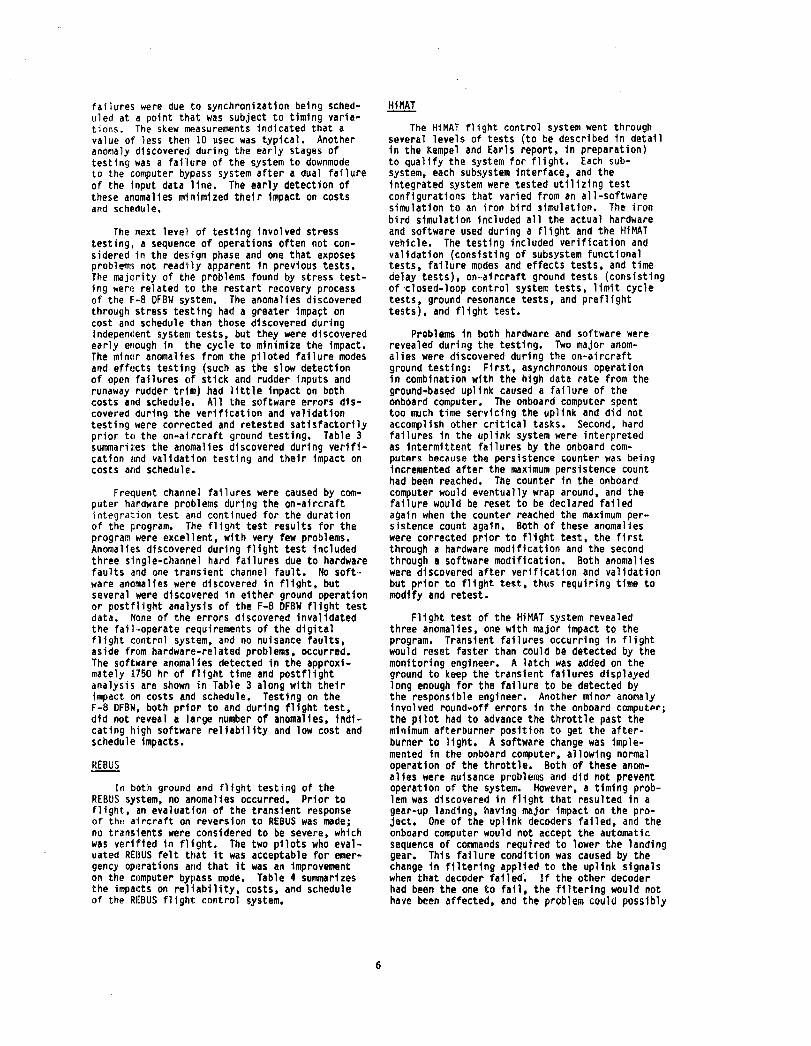
An experimental dissimilar backup system, REBUS (Fig. 3), was incorporated into the F-B DFBW system to investigate the concept of dissimilar software as backup for the primary system. To include software dissimilar from the synchronous F-8 DFBW system, the REBUS system is asynchronous, operating at a 20-msec frame rate. Each of the triplex REBUS channels operates on dedicated sensors, with the channelsensor unit Independent of the operation of the other units to avoid asynchronous data crossstrapping problems; each channel operates on slightly different input due to computer skew. The control laws provide minimal augmentation, little more than the capability to return to base and safely land. Three-axis fixed-gain rate damping with some nonlinear stick shaping and deadbands comprise the control law design. The REBUS system does modify the gains for landing and approach, but the up-and-away gains are constant throughout the flight envelope. Transfer to the REBUS system from the primary system occurs as a result of channel failures. The REBUS software is initialized using a full complement of sensor inputs and existing control surface commands.

.!:!..iMAT
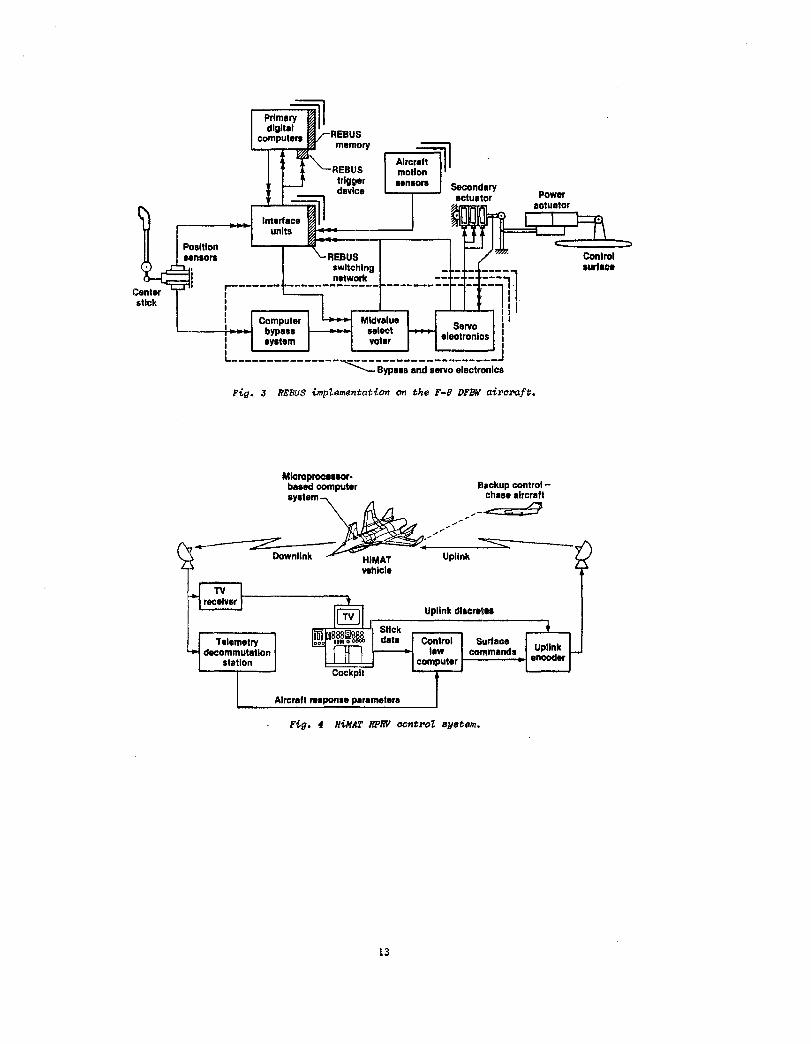
The HiMAT vehicles were air launched from a B·,52 aircraft and remotely controlled by a pilot located in a ground cockpit (Fig. 4). Tne primary control laws were resident in a ground-based computer with the backup control system included in the onboard backup computer. Tne onboard computers operated asynchronously with the ground system and each other. The backup system coul d be controlled from either the ground or a TF -104 chase ai rcral't.
The advanced concept s inc I uded in the H1I1AT e~periment were composite and metallic structures, close-coupled canards, aeroelastic tailoring, digital integrated propulsion control system (IPCS), relaxed static stability, and ground and airborne digital fly-by-wire controls. The design maneuverability goal, a sustained 8-g turn at Mach 0.9 and an altitude of 25,000 ft, was achieved during flight test along with sustained supersonic flight. Dual onboard computers, opc!rat i ng asynchronous ly, provi ded the i nterfaces with the ground and various vehicle subsy:;tems, and each provided independent capabi lay fOl' a safe return. The system also included dual ell!ctrical, hydraulic, and flight control systems (dl!S i gnated as primary control system and backup control system) as well as triplex angular rate sensors for all three axes, triplex lateral and nor-mal accelerometers, and duplex air data sensors (Fig. 5). A single sensor of each variety was designated as backup sensor, and only it was used by the backup control system; the primary system USE!d a 11 the sensors. The servo actuators were int.erfaced to the onboard computers through a ser'vo actuator electronics box, which translated thE~ servo COlllnands, fed back the actuator data, anel prov1ded failure detection for the elevon seno actuator system.
The HiMAT vehicles were tested in two configurations, one with relaxed static stability and one with Ilositive stability margins. The stable configuration control laws were fullauthority rate-damper systems. The control system includE!d a launch mode to assure separation from the carrier aircraft and a degraded primary mode, which was selectable by the ground pflot and allowed the pilot to maintain conventional control for conditions such as loss of power in an engine-out situation. The pilot was given the option of choosing the degraded primary mode or the backup control system.
The backup control system for the stable aircraft contained a variety of automatic modes to enSIJre recovery of the HiMAT vehicle from unusual or I~xtreme conditions and to provide a safe return capilbil1ty. The backup control system was also capable of orbiting at a specified altitude when ther'e was a loss of uplink or downlink signal. The backup control system was a multi rate system opel'ating at 10-, 20-, and 100-msec frame rates. The onboard computer system also provided total control of the H1MAT engine with the primary IPCS res vdent in the backup computer and the backup , IPCS included in the primary computer. The IPCS included a normal operation mode, it combat mode, and a high-stability mode.
4
In the relaxed-stability operation, a fixedgain pitch rate feedback loop was included in the onboard primary control system to reduce excessive system time delays. As in the stable condition, the primary control system included it launch mode and a degraded primary mode. The backup control system for the relaxed-stability operation contained seven modes (listed in Table I) and was a full-authority, three-axis, multirate system. The backup control system was always initialized through the recovery mode, which brought the aircraft to a straight-and-level flight condition. Once the HiMAT vehicle was in a straight-andlevel flight condition, the backup control system would transition to heading hold mode and altitude hold mode, If no other comm~nd was received by the heading hold mOde or altitude hold mode within 25 sec, the backup control system W01Jld transition to the orbit mode. Airspeed hold mode and landing mode were also included in the backup control system.
The asynchronous interactions of the airborne system with the ground system and the ground rule that no single failure would result in loss of the ve~icle resulted in a complex design for the HiMAT f1 i ght systems management funct ions. Data transfer was minimized by allowing each computer to operate independent functions that required little or no dnta exchange. The faults detected by the onboard computer system included those that caused automatiC transfer to backup mode, those that prevented automatic transfer to baCKUp mode, those that indicated mission abort conditions, and thc)se that indicated caution conditions. The onboar,j computer faul t detection incl uded actuator monito,-ing, hydrauliC system monitoring, electrical sy';tem monitoring, uplink system monitoring, downl1nk system monitoring, and computer self-test diagnostics operating in the primary computer. The uplink system monitoring and computer selftest diagnostics were duplicated as independent functions in the backup computer. The ground failure detection and management for the singlestring ground system included downlink integrity testing, uplink integrity testing, real-time loop integrity testing, computer heartbeat monitoring, stick input checks, I/O testing, air data testing, and an9Ie~of-attack testing.
AFTI/F .. 16
The F~16 airframe is statically unstable in the pitch axis, necessitating a full-time, fullauthority fight control system. The AFTI/F-16 aircraft (Fig. 6) was developed with a triplex, asynchronous flight control system. Goals of this system included dual-fail operate capability and thl! development of advanced control modes for decoup;ed motion. The flight control system consists of three computers, an actuator interface Uflit, integrated servo actuators, a fli ght control panel, and associated sensors, controllers, ~nd pilot displays (Fig. 7). The system also includes a limited triplex analog independent backup unit. The asynchronous flight ,control computers are identical and operate at a frame rate of approximately 16 msec, with some functions operating at about 31 and 25 msec. The primary sensors (pitch rate gyros, roll rate gyros, and yaw rate gyros) are triply redundant.

Thl! primary c.ontrollers (pitch stick, roll stick, and rudder pedals) operate on three active and one backup transducer. An additional triply redundant controller was added to the throttle (ali a throttle twist grip) to provide decoupled pit.ch control. The primary pilot-vehicle interfa(:e consists of two multipurpose displays that provide dual-redundant digital flight control system mode and control status as well as weapons management. The integrated servo actuators contain three electrohydraulic valves operating with two independent hydraulic fluid sources, differential pressure sensing, and lVDT pOSition feedback sensors.
The AFTI/F-16 system contains eight complex modes (Table 2) with multiple submodes controlled by internal switching within the primary modes. These submode switches. in combination with the asynchronous operation of the system generated difficulties in both ground and flight test. Because of the static instability of the pitch axis, all the longitudinal modes require pitch feedback, in cruise conditions as well as takeoff and landing. The standard normal mode is used for takeoff and landing as well as cruise and is the primary digital mode for all failure conditions. Within this standard normal mode are conditions that allow the control laws to reconfigure for sensor and controller failures, which were never flight tested, as well as for landing and takeoff conditions. Along with the primary standard normal mode, three other standard modes are implemented to provide task-tailored control, air-to-air gun mode, air-to-surface gun mode, and air-to-surface bomb mode. Each of these modes, including the standard normal mode, have decoupled counterparts that can be selected through a switch on the sidestick controller. These modes, with the exception of the no-fail condition of the standijrd normal mode, contain multiple conditions for submode switching. The various modes and their command options are shown in Table 2. The decoupled modes allow independent control of specific aerodynamic parameters, such as angle of attack, angle of sideslip, pitch attitude, and yaw attitude, as shown in Fig. 8.
To deal with the asynchronous interactions and the dual-fail operate goal using a triplex system, the redundancy management software design for the AFTI/F-16 fli!lht control system is as complex as the control law design. Software input voting for the redundant sensors, output voting for actuator commands and status, health checking of computer hardware, and preflight systems monitoring ar,! the major elements of the fail-ure management system. The input sensors, controllers, dnd discretes are hardwired into each computer channel and then digitally transmitted between each asynchronous channel. The channels then independently seler.t the appropri,lte input by averaging the nonfailed like sensors. The output commandS for all surfaces are transmitted to each channel and selected, much like the input sensor signals. Unlike the input sensor algorithm, the output command selection chooses a single channel's output as determined by internal logic. This output selection method was developed to maintain reasonable trip lev(!ls in the asynchronous system with reduced nuisance failures at the actuator level. Output
5
command failures are used to identify a failed computer; two surface command failures in a given channel indicate a defective channel, and all surface commands are assumed failed in that channel. A detected failure is reported to the failure manager, which then takes the appropriate action. The preflight monitoring uses both passive and active testing to determine the status of the flight control computers, actuators, various input sensors and controllers, and the analog ba(.kup system. A reset capabll ity is included to allow the processor to reset a transient failure or for nuisance failures caused by asynchronous data transfer in any of the flight control system input sensors, controllers, actuators, or processors. An independent I/O capability is included in the redundancy management design of the AFTI/F-16 flight control system to allow the loss of only the processor, not the I/O information, in the event of a digital channel failure. The tranSition to the analog independent backup unit occurs only if the system cannot determine which of the two remaining channels is good after an output failure or self-test failure detection.
Test Experience
All the flight control systems described in this paper experienced extensive verification and validation and ground testing prior to being flight tested. In this section, the results of testing for each flight control system (after the elimination of coding errors, which are not discussed here) are compared and evaluated against the criteria discussed previously: reliability, costs, and schedule delays. The results of formal verification and validation testing, onaircraft ground testing, and flight testing are included. Short descriptions of the actual testing are included as background to the test res~lts themselves.
F-8 DFBW
As a new and untried experiment, the F-8 DFBW fli1ht control system went through extensive analysis (described in detail in Ref. 1) before and during the design process in order to validate the design: this level of analysis greatly facilit~ted the testing. The actual system testing was broken intI) two areas, subsystem testing and integrated sys~em testing, both of which included breadboard, iron bird, and flight testing. The verification and validation testing consisted of independent system testing, stress testing, and fdilure modes and effects testing. The majority of the independent system testing for the F-B DFBW design at Ames-Dryden was done on the iron bird and covered control laws, executive, computer I/O, computer redundancy management, sensor redundancy management, in-flight self-test, preflight test, displays and controls, primary-bypass system transfer laws, and downlink system. Because the synchronization was critical to the system operation, extensive synchronization testing was done, including tests of the time required for all channels to acquire sync and tests of skew between channels as they exited the sync routine. Occasionally during early testing, a channel sporadically lost sync, or all three channels failed to achieve sync upon power up: consequently, the software was modified. The
failures were due to synchronization being scheduled at a point that was subject to timing varia" tions. The skew measurements indicated that a value of less then 10 ~sec was typical. Another anomaly diSCOvered during the early stages of testing was a fai"lure of the system to downmode to the computer bypass system after a dual failure of the input data line. The early detection of these anomalies minimized their impact on costs and schl~dule.
The next level of testing involved stress test i ng I a sequenc:e of ope rat ions often not considered in the design phase and one that exposes problems not readily apparent In previous tests. The majority of the problems found by stress testing wer(: related to the restart recovery process of the 1'-8 DFBW system. The anomalies discovered through stress testing had a greater impa~t on cost a nil schedul e than those di scovered duri ng i ndepen(Jent system tests, but they were di scovered early enough in t.he cycle to minimize the impact. The minor anOmaliE!S from the piloted failure modes and eff(!cts testing (such as the slow detection of open failures Clf stick and rudder inputs and runaway rudder trim) had little impact on both costs and schedule!. All the software errors discovered during the verification and validation testing were corrected and retested satisfactorily prior to the on-aircraft ground testing. Table 3 summari l:es the anoma 1 i es discovered duri ng veri fication clnd validation testing and their impact on cos ts arid schedu Ie.
Frequent Channel fai I ures were caused by computer h~rdware problems during the on-aircraft integration test and continued for the duration of the program. The flight test results for the program were excellent, with very few problems. Anomalies discovered during flight test included three single-channel hard failures due to hardware faults and one transient channel fault. No software anomalies were discovered in flight. but several were discovered in either ground operation or postflight analysis of the F-8 DFBW flight test data. None of the errors discovered invalidated the fail-operate requirements of the digital flight control system, and no nuisance faults, aside from hardware-related problems, occurred. The software anomalies detected in the approximately 1750 hr of flight time and postflight analysis are shown in Table 3 along with their impact on costs and schedule. Testing on the F-8 DFBW. both prior to and during flight test, did not reveal a large number of anomalies, indicating high software reliability and low cost and schedule impacts.
In both ground and flight testing of the REBUS sy:stem, no anomalies occurred. Prior to f1 ight, an eva I uat 'Ion of the trans i ent response of the a'i rcra ft on revers i on to REBUS was made; no transients were considered to be severe, which was veri'fied in flight. The two pilots who evaluated REBUS felt tllat it was acceptable for emergency opl!rations arid that it was an improvement on the computer bypass mode. Table 4 summarizes the impal:ts on reliability, costs, and schedule of the RI,BUS fl1 ght: control system.
6
HiMAT
The HiMAT flight control system went through several levels of tests (to be described in detail in the Kempel and Earls report, in preparation) to qualify the system for flight. Each subsystem, each subsystem interface, and the integrated system were tested utilizing test configurations that varied from an all-software simulation to an iron bird simulation. The iron bird simulation included all the actual hardware and software used duri ng a f1i ght and the Hi MAT vehicle. The testing included verification and validation (consisting of subsystem functional tests, failure modes and effects tests, and time delay tests), on-aircraft ground tests (consisting of 'closed-loop control system tests, limit cycle tests, ground resonance tests, and preflight tests), and flight test.
Problems in both hardware and software were revealed during the testing. Two major anomalies were discovered during the on-aircraft ground testing: First, asynchronous operation in combination with the high data rate from the ground-based uplink caused a failure of the onbOArd computer. The onboard computer spent too much time servicing the uplink and did not accomplish other critical tasks. Second, hard failures in the uplink system were interpreted as intermittent failures by the onboard computers because the persistence counter was being incremented after the maximum persistence count had been reached. The counter in the onboard computer would eventually wrap around, and the failure would be reset to be declared failed again when the counter reached the maximum persistence count again. Both of these anomalies were corrected prior to flight test, the first through a hardware modification and the second through a software modification. Both anomalies were discovered after verification and validation but prior to flight test, thus requiring time to modify and retest.
Flight test of the HiMAT system revealed three anomalies, one with major impact to the program. Transient failures occurring in flight would reset faster than coUld be detected by the monitoring engineer. A latch was added on the ground to keep the transient failures displayed long enough for the failure to be detected by the responsible engineer. Another minor anomaly involved round-off errors in the onboard comput~r; the pilot had to advance the throttle past the minimum afterburner position to get the afterburner to light. A software change was implemented in the onboard computer, allowing normal operation of the throttle. Both of these anomalies were nuisance problems and did not prevent operation of the system. However, a timing problem was discovered in flight that resulted in a gear-up landing, having major impact on the project. One of the uplink decoders failed, and the onboard computer would not accept the automatic sequence of commands required to lower the landing gear. This failure condition was caused by the change in filtering applied to the uplink signals when that decoder failed'. If the other decoder had been the one to fail, the filtering would not have been affected, and the problem could possibly

have gone undetected. Again, the onboard computer software was changed to correct the problem.
The majority of these anomalies discovered during testing were related to the interfaces between different components of the asynchronous system" These types of problems can be detected only in an integrated environment that exercises the system in the same way it will be used during flight.. Table 5 summarizes the HiMAT anomalies and their impact on reliability, costs, and schedule delays.
AFTI/F··16
The AFTI/F-16 system began verification and validation testing prior to completion of the software integration and debug stage; however, testing did not officially begin until all the coding errors in the system had been tested and corrected. Early in the testing process it was di s tovElred that the hi gh-ga i n cont 1'01 1 aws were i ntera(:t 1 ng adversely with the redundancy management software. This interaction magnified the differences in input values resulting from asynchronous skew to create output and channel failurE~. After the gains were reduced, output and ch~nnel failures still occurred. The gain magnification of input differences exceeded the out.put tolerance during dynamic maneuvers, resulting in the addition of a rate-of-chaRge factor to adjust the output tolerance. Both condftlons were discovered prior to the actual verification and validation and had minor impacts on both costs and schedule. Major anomalies disLovered during the verification and validation testing jnc1uded air data and bus contentlo~ anomalies. An undetected bias failure 1n air data below the IS-percent trip level would cause channel failures; a bus ,ontro11er contention problem could cause loss of the digital flight control system. Both anomalies required soft~lare modi fi Cilt ions but were di scovered early enough in the project development to have only moderate effects on costs and schedule.
Greater cost!; and schedule delays were incurred from thE! results of the ground gunf; re tests. The V'ibrCltion in the lateral accelerations and yaw rate from the gun firing caused output and channEll failures because of the highgain magnificatic)O. The time required to modify and ret,est the software pri or to flight test generahd a delay in the schedule. Flight test results of the AFTl/F·16 system included nine flight .control system failures in 177.2 flight hours. All these failures resulted in either' an interruption of the miSSion, with some points not flown, or a return and land requirement. Seven of the in-night errors were the result of asynchronous skew effects on submode switching; each channel would trigger a change in a submode switch I~t different times, resulting in output failure!! and channel fallures. Several of the failure conditions delayed the next flight by one or more days and reduced the all owab 1 e f11 ght envelopl! or eliminated a mode. Two of the inflight failures were transient failures that could not be dupl icated and did not reoccur; considerable engineering time was lost in the duplication Iittempt. Another in-flight fal1ure was the result of an avionics failure, not a failure of
7
the flight control system. The avionics system failure induced random mode changes in the flight control system at very high rates; consequently, the flight was discontinued, and the aircraft returned and landed. A software modification was made to the digital flight control system (rather than to the avionics) to prevent a reoccurrence because the failure could not be duplicated and did not reoccur. One major result of the first phase of the AFTI/F-16 program was that throughout the flight test program no failure caused a reversion to the independent backup mode. The failures discovered during the testing of the AFTI/F-16 system are summarized in Table 6 along with their impact on the software reliability, costs, and schedule.
Digital Flight Control Systems Evaluation
A 11 four ai rc'raft completed successful f1 i ght test programs with the number of anomalies occurring varying from one program to another. The four digital flight control systems, F-8 DFBW, REBUS, HiMAT, and AFTI/F-16, are evaluated in relationship to software reliability, increased costs, and SChedule delays. Software reliability, defined as the inverse of the number of in~f1ight nonnuisance failures, was high on all the flight control systems, and all systems were proven safe throughout their flight envelopes. The F-8 DFBW aircraft experienced no software-related problems in flight, though some were discovered in postflight analysis. The REBUS system exhibited no anomalies during ground or flight test. The HiMAT system had one major in-flight anomaly, Which resulted in a gear-up landing on the lakebed, and two minor anomalies. 1he AFTI/F-16 aircraft experienced nine in-flight anomalies during the first phase of the program. In terms of reliability, the two highly complex, asynchronous systems. the HiHAT and AFTI/F-16, had the most in-flight anomalies.
Seven of the nine AFTI/F-16 anomalies were due to a comb; nat; on of asynchronous operation, complex control laws, and complex redundancy management design. These problems were related to the procedure of crosslinking data between channels and then USing a good-channel average; the skew between channels was often just sufficient to cause the channels to use inputs differing enough that output failures or channel failures, or both, resulted. The asynchronous operation of the AFTI/F-16 system increased the complexity of 1ts flight control system. The deSign of the REBUS system intentionally avoided many of the problems associated with the asynchronous effect on crosslinked data. The REBUS system was able to avoid these effects by not crosslinking any data and allowing ea,h channel to operate independently on independent inputs. with the commands evaluated in the actuators instead of in the flight control software. The REBUS was also developed as a simple system to remove extra complexity that could adversely affect the asynchronous operation. The synchronous operation of the F-8 DFBW flight control system assured that each channel operated on the same data at the same time, therefore output failures due to data crosslinking and skew conditions could not occur. The HHIAT system's major in-flight anomaly was due to a timing problem when the upl'ink

decoder failed. The complexity of the AFTI/F-16 and Hi/MT systems made it di fficult to predi ct and test an the conditions prior to flight. Two assessmlmts that can be made from these results are that complexHy is a major factor in flight control system so1'tl'lare reI iability and that synchronization and ilsynchronization do not. by themse 1 ves. determine rel1abil ity. '
Inc,"eased costs and schedule delays (related in that schedule delays increase the cost of a system) were encountered by all the systems to differing degrees. The AFTI/F-16 testing did not ori!linally allow variation of skew condi-t ions nor were thE! skew condi t ions measured duri ng the early tests. Consequently. there was no method for determining or setting the exact tl!st condition. which varied from one test point to another. Additional testing was then reClu i red to ,"epeat and correct anoma 1 i es. incurring schedulE! delays and increased costs. As the program progressed and several anomalies occurred in flight. the capability of adjusting the ske~1 conditions was included into the test facllity for the J\FTI/F-16 system. A related factor involved in the schedule delays and inCreaSE!d costs WetS the difficulty with the asynchronous opercttion in determining which skew conditions were actually worst case for which flight conditions. The AFTI/F-16 system, with its. compl icat-ed gain structure. had varying ga ins at each f1 i 9ht condit i on. whi ch presented difficulties in de!termining worst-case conditions. Skew effects were eval uated early to determi ne the to 1 E!ranCe val LIes. not to determi ne worst-case skew at different flight conditions and different modes. The very large matrix that would need to De evaluated disc(luraged the evaluation. The difficulty connected with worst-case skew prediction resu 1 ted 1 n cont i nuous ly repeating a test condition untll the anomaly reoccurred. With a simpler system. a thorough evaluation of different skew conditic,ns would have been poss1ble. allowing the elimination of problems early in the design process, thus reducing schedule delays and cost increasE!s. The REBUS program avoided these difficultiE!s by usin~1 a simple system. The skew on the REBliS system ~Ias monitored. and the results of Doth f1 i ght anel ground tests indi cated very 1 ittle variation. which when combined with the simple design resulted in no difficulties with the asynchronous system. The F-8 DFBW flight control system testing was fairly straightfUI'ward •. with an E!asily defined test matr;x. The test matrix did not need to be expanded to account for differ'ent skew conditions. Some design problems were addressed early in the F-8 DFBW flight control system verification and validation stage, but they had minimal impact (In both cost and schedule. The synchronization of the computers for the system created some difficulties, DUt once the timing problems, were corr'ected. no further anomal ies arose. One inference is that asynchronous systems need to De' simple to avoid increased testing and protect against in-flight anomalies.
Another factor to be considered in minimizing schedule! delays and cost increases is the system development of the digital flight control system as an integrated system. The F-8 OFBW and HiMAT systems were developed as integrated systems;
all the interfaces were developed along with the flight control system. With this integrated design. the problems associated with interfaces and interactions were greatly reduced. This is reflected in the low anomaly rate during flight and ground tests of these systems. The AFTI/F-16 f,l i ght cont ro 1 system was developed sepa rate ly from many of its interfaces. and consequently. the testing process revealed a number of anomalies that resulted from the interactions between systems. The integration-related anomalies continued through ground test. as evidenced by the ground gunfire failures. and in flight. as in the multiple-mode switching anomaly. While the asynchronous operation of the AFTI/F-16 system impacted these anomalies. the integrated environment had a larger effect. The integrated design process was especially helpful for the HiMAT vehicle. A tightly knit group of people developed the HiMAT systems together. which allowed close communication and problem resolution early in the development cycle. The HiMAT systems were viewed as a large system with many subsystems. and an effort was made to insure that all the interfaces were properly integrated. The early integration in an environment that exercised the system in the same way as it would be in flight allowed the resolution of anomalies prior to flight and minimized schedule delays and cost increases.
Concluding Remarks
The AFTI/F-16 system was very complex in its control laws and redundancy management deSign. Its asynchronous operation coupled with a goal of dual-fail operate for a triplex system and the multimoded. complicated control structure resulted in a series of both in-flight and ground test anomalies. The HiMAT system. also complex, was tested in an integrated environment that closely simulated the flight environment, thus allowing early detection of potential problems and minimizing in-flight anomalies. The REBUS system had a very simple control structure and limited the data crosslink to avoid proDlems associated with asynchronous operation. The F-8 DFBW system. while not extremely complex, had sufficient complications to show that for some situations a synchronous system may be better for complex systems. As an integrated design. the F-8 DFBW system avoided problems that could have occurred and resulted in a highly successful and relatively trOUble-free test pro9ram.
The evaluation of the F-8 OFBW. RE8US. HiMAT, and AFTI/F-16 flight control systems lead to some interesting conclusions:
1. The asynchronous or synchronous operation of the systems was not 1n itself a determining factor in the number of anomalies and difficulties encountered during testing.
2. The complexity of the system ca~ cause major impacts in terms of anomalies during both ground and flight testing.
3. A simple asynchronous system without a complicated data crosslink structure may be easier to develop than a synchronous system of the same magnitude.

4. A system designed as an integrated system, including all interactions and interfaces, has a reduced level of difficulties in testing and opl!rat ion.
20eets, D~lai n A., Lock, Wil ton P., and Megna, Vincent A., "Flight Test of a Resident Backup Softwar'e System," NASA TM-86807, 1986.
References
lSlalai, Kenneth J., Jarvis, Calvin R., Krier, Gary E", Megna, Vincent A., Brock, Larry D., and O'Donnull, Robert N., "Digital Fly-By-Wire Flight Contro1 Validation Experience," NASA TM-72860, 1978.
3l shmael, Stephen D., Regenie, Victoria A., and. Mackall, Dale A., "Design Implications From AFTI/F-16 Flight Test," NASA TM-86026, 1984.
4Joyner, Capt. Mark L., and Heimple, Lt. Col. Harry H., "AFTI/F-16 Digital Flight Control System Evaluation," AFFTC-TR-83-48, Dec. 1983.
Table 1 HiMAT backup flight control system modes and functional characteristics
Mode
Recovery
Orbit
Straight and level Turn 1
Turn 2
Land
Engine-out glide clnd fl are
Mode function
Backup control system initialized in this mode Brings the vuhicle to level flight (~ = 0 ft/min) Orbit mode will be entered at expiration of 25-sec
timer following transfer to backup control system (unless exit orbit has been selected)
Vehicle will climb to one of three orbit altitudes or dive to 25,000 ft if backup control system is entered above this altitude
Orbit altitudes are 25,000 ft, 10,000 ft, and 5000 ft Altitude, quasi-heading, and speed or Mach hold Attitude command roll rate Roll rate command roll rate All cl imbs at 100 ft/sec Dives above 10,000 ft at 100 ft/sec Dives below 10,000 ft at 60 ft/sec Scheduled air'speed and altitude rate command as a
function of radar altitude Pilot is able to modulate airspeed and altitude
rate within limits; minimum airspeed is 185 knots Alternative land mode provided in the event of
radar altimeter failure Commanded air'speed of 215 knots with modulation
capability Flare initiated at 550 ft radar altitude with
elevon control transfers from afrspeed command to altitude rate command
9

Table 2 AFTI/F-16 system modes and command options
Control I er
Mode Pitch stiCK Roll stick Rudder pedal Throttle twist
Command opt ion
Standard normal Normal acceleration Roll rate Rudder deflection None Standard air-to-surface Normal acceleration Roll rate Flat turn None
bombing Standard air-to-surface Pitch rate Roll rate Flat turn None
gun Standard ai r-'to-ai r gun Pitch rate Roll rate Flat turn None Decoupled normal Flightpath maneuver Roll rate Translation Translation
enhancement Decclupled ai r,-to-surface Fl i ghtpath maneuver' Roll rate Flat turn Direct lift
bombing enhancement Decllup led ai r,·to-surface Pitch rate maneuver' Roll rate Pointing Poi nt i ng
gun enhancement Dec()up led ai r··to-a i r gun Pitch rate maneuver Roll rate POinting Pointing
enhancement and f1 i ghtpath maneu·, ver enhancement
Table 3 Major F-8 DFBW system test anomalies
Impact Test type
Verification and va I idat ion
Ground test and operation
Flight tl~st
Anomalies
Continued operation for' some sync faul ts
No CBS downmode for dual input data line failure
Software problem in power recovery process
Sensor fault logic errors Incorrect internal interrupt
handling None
Reliability
Pos it ive
Costs Schedule
Low Low
Low Low
Low low
t~derate Moderate ~loderate Moderate
None None Analysis of ground and Fault detection logiC des'lgn error' Moderately negative Moderate Moderate
flight test data Fault recovery logic deficiency Moderately negative Moderate Moderate
Table 4 REBUS system test results
Test type
Verification and validation Ground test and operation Flf ght test
Anomalies
Minor None None
10
Impact
Reliability Costs Schedule
Positive
Low None None
Low None None

Table 5 HiMAT system major test anomalies
Impact Test type AnOmi!ll es
ReI iabil ity Costs Schedule
Verification and validation Onboard computer failure at Low Low too high uplink data rate
Ground test and operation Hard upl ink fail ures appeared Moderate Moderate transient to ollboard computer
FI i ght test Uplink decoder timing problem Highly negative High High Transient failures reset faster Moderately negative Moderate Iloderate
than could be monitored Excess throttle to get 110derately negat i ve Moderate MoMrau
afterburner
Table 6 AFTI/F-lli system major test anomalies
Impact Test type Anoma lies
Reliability Costs Schedule
Vf!rffication and Output and channel failures due Low Low validation to high gains
low output tolerances in dynamic Low Low maneuvers
Channel failure dUE! to air data bias Low low Bus contention caused.channel failure Low Low
Ground test and operat ion Output and channel failure during Moderate Moderate gunfire test
Flight test Leading edge flap ()utput command Highly negative High High failure
Channel failure due to three output Highly command failures in one channel
negative High High
Left and right canard output failures Highly negative High High Oual channel failur'e due to dual Highly negat! ve High High
output command fili lure left and right flaperon output Highly negati ve High High
command failures Left and right canard output failures Highly negative High High Channel failure due to three output Highly negathe High High
command failures in one channel Multiple-mode switc:hing due to Highly
avionics fault negati ve High High
11

Fig. 1
Primary II digital
computers
Interlace II
ECN 3312
P-8 DFBW airocmft.
Aircraft II motion sensors Secondary
actuator
units j-ooI._>----------J
----, -- - - ----, I
r------- ------------- --------- -----, I I I II I I III I III I Computer Midvalue I I I bypass select Servo I I system voter electronics I , I L. _________________ "o ___________________ J
"---Bypass and servo electronics
Fig. 2 F-8 DFBW ~ight controot system.
12
u--·--Il
Primary II digital
compute,. REBUS memory
"'-REBUS trigger device
Interface II units ~---
REBUS awltchlrtg networlc
Aircraft II motion
Secondary actuator
'. 0
-:::-'1 ,...------- -----------_.- --------- ---,. I II, : d : Computer Mldvalue Servo II
L-__ -l, ... -.l bypass "Ieet electroniCs I ,Iystem Yoter I I - -,
'----------------~=B;;a~;;;-;.;.;;;i;~t;;~
Fig. 3 REBUS imptementation on the F-8 DFBW aircraft.
Mlcroprocelaor· baled computer Backup control-
", ,,'
/-...::: <=<-00 9-IYltem~ chase aircraft
::7 ~' -::s;
Telemetry deeommutatlon
station
Downlink HIMAT Uplink vehicle
Uplink dlacrtt"
..... ,.....,L:::;:;::;:~..J, Stick data Control Surface
lew commands computer
Cockpit
Aircraft ,"pon" parameters
Fig. 4 HiMAT JrPRV control. system.
13
Uplink encoder

prlmarv] Sensor data Position and discrete commands
! I Primary Position feedbacks actuators sensors
Control dlscretes • Flight tent 1-1 Downlink data Test control
Umbilical instrumentation Proportional uplink Primary Computer data (test)
system Uplink discrete. onboard Power and conlrol Proportional uplink computer Position feedbacks .~
Recelverl Sensor data Primary decoder 1 I-- power
Ii Intercom
Recelverl Position and L-
Backup decoder 2 Uplink dlacretas discrete commands actuators
Backup Throttle command Backup Sensor data onboard Position and discrete commands. IPCS sensors computer
Posilion feedbacks actuators
IPCS ] Sensor data t t Power and control Backup power sensors •
Fig. 5 HiMAT airborne computer-aircraft systems interface diagram.
ECN 20425
Fig. 6 AFTI/F-16 airoraft.
14

Flight control r--'
Integrated Leadi ng -edge
panel servoactuatDrs flap system
Side-sticl( controller Actuator
,I
interface ~ Throttle unit Angle-of-attack controiler f-- - sensors
'""" ] t -- Sideslip
I pedal 10-- I
sensors , Flight Pneumatic Roll rate control
gyros computers sensor
: I r-----m
l assembly
"" '"J :---- ~p sideslip ,- senSDr gyros assembly
YIWI rate - Aircraft '----gyros switches
Normal
''''''''"J accelerometers
Lateral Avionics accelerometers multiplex
bus
Fig.? AFTI/F-16 flight oontrot system.
15

(a) Vel'ti"al tl'Clnslation: vel'tical velocity cont~ol at constant pitch attitude.
(b) Di~ect lift: vBl'tica1. fUghtpath cont~L at constant angle of attack.
(c) Pitch pointing: pitch attitude control at constant j1ightpath ang1. ••
(d) Latel'ClL tranelation: lateral velocity control at constant yaw attitude.
(e) D1.r8ct 8idefo~ce: directional. f1.ightpath cont~ol. at lIero sideslip angl.e ..
(f) Yaw pointing: directionaL attitude control at constant j1ightpath angle.
Fig. 8 AFTI/}>'-16 decwuptfld controZ.
16

1. Report No. I 2. Government Acceuion No. 3. Recipient's Calliog No.
NASA TlI-S8271 4. T,tle and Subtitle 5. Report Dlte
August 1986 EXPERIENCE WITH SYNCHRONOUS ANO 6. Performing Orlll'nization Code ASYNCHRONOUS DIGITAL CONTROL SYSTEMS
7. Authorl.1 8. Performing Orlll'nlZl1lon Report No.
Victoria A. Regenle, Claude V. Chacon. H-1372 and Wilton P. Lock
10. Work Unit No. 9. Perlo< ming Organization Name and Addr .. RTOP 505-66-02
NASA Ames Research Center Dryden Fl'j ght Research Fac1lity 11. Contrlet or Grant No.
P.O. Box 273 Edwards, CA 93523-5000
13. Type of Report lind Period Covered
12. Sponsoring Agnncy Name lind Address Technical Memorandum National Aeronautics and Space Administration
14. Sponsoring Agency Code Washington. D.C. 20546
15. Supplementary Notes
Prepared ilS AIAA-86-2239-CP for presentation at the AIAA Guidance. Navigation, and Control ConferenCE!, Williamsburg, Virginia, August 18-20, 1986.
t 6. Abstract
Flight control systems have undergone a revolution since the days of simfle mechanical linkages; presently the most advanced systems are fu I-authority. full-time digital 'systems controlling unstable aircraft. With the use of advanced control systems. the aerOdynamiC design can incorporate features that allow greater performance and fuel savings, as can be seen on the new Airbus design and advanced tactical fighter concepts. These advanced aircraft will be and are relying on the flight control system to provide the stability and handling qualities required for safe flight and to allow the pilot to control the aircraft, Various design philosophies have been proposed and followed to investigate system architectures for these advanced flight control systems. One major area of discussion is whether a mu 1t ichanne I di gita I control system shoul d be synchronous or asynchro~ nous. This paper addresses the flight experience at the Dryden Flight Research Facility of NASA's Ames Research Center with both synchronous and asynchronous digital flight control systems. Four different flight control systems are evaluated against criteria such as software reli-ability. cost increases, and schedule delays.
17. "ey Words lSullllllted by Authorl_" 18. Distribution Statement
Asynchronous systems Unclassified -- Unlimited Digital f1"lght control systems Flight control system architecture Synchronou!; systems
STAR category 08
19. !«urity aallif. (of this repon, /20. Stcurity Oolllf. lot this PlIIII /21. No. of Pages 1 22. Price' Unclassifh!d Unclassified 17 AD2

End of Document