experience with motor drive™ for high-voltage circuit breakers with... · experience with motor...
TRANSCRIPT
– 1 –
EXPERIENCE WITH MOTOR DRIVE™ FOR HIGH-VOLTAGE CIRCUIT
BREAKERS
A. Bosma, ABB AB, tel. +47 240 782403, [email protected]
Pattarit Pengchui, EGAT, [email protected]
Narong Tantichayakorn, PEA, [email protected]
Abstract
Motor Drive™ was introduced in 2001 as a new and innovative operating mechanism for circuit breakers
in the voltage range between 72.5 kV and 170 kV. In Motor Drive™ the number of moving parts has
been reduced to one (1). It is fully electronic and includes monitoring of all essential funct ions (speed,
timing, energy consumption, etc.) without need for additional sensors. Energy storage is no longer
dependent on springs or compressed air. Energy transfer from the storage to the activator no longer
depends on chains, hydraulic fluid or compressed air. The contact speed is factory set and during
operation the speed is continuously monitored and adjusted (if necessary) via a feedback control loop.
The fact that the speed is electronically controlled results in a consistent timing and contact tra vel that
makes the combination circuit-breaker – operating mechanism extremely suitable for controlled
switching applications.
Circuit breakers with Motor Drive™ have been delivered to utilities all over the world and are used in
a wide variety of applications and environments: from daily switching (20 times) of arc furnaces in harsh
environments to switching in substations close to populated areas. While the first application focuses on
mechanical endurance, the second focuses on the Motor Drive™ being quiet when operating, thus not
disturbing people that live close to the substation.
In Thailand circuit breakers with Motor Drive™ have found their way to EGAT and PEA. This paper
describes the design and function of the Motor Drive™ as well as the experience with this drive in
Thailand.
1 Introduction
Development of transmission circuit breakers is most often described in terms of the evolution of
interrupter technologies and the insulating mediums they employ. The 1950’s to 1970’s were dominated
by oil minimum and air-blast designs. During the 1970’s, SF6 technology began to supersede oil
minimum and air-blast technologies. SF6 gas interrupters continued a trend of providing higher ratings
per interrupter and thus simplifying the primary system construction of circuit breakers.
Substantial progress has been made in increasing reliability and reducing maintenance requirements of
SF6 circuit breakers. The most successful approaches in these respects have focused on modular designs
reducing the number of components in the interrupter (see also [1]). The majority of circuit breakers
rated above 72.5 kV delivered today incorporate simple, reliable SF 6 interrupters.
In contrast to the major performance leaps made in interrupter technologies, circuit break er operating
mechanism (drive) designs have seen less dramatic development in core functional performance during
the past fifty years. Of course there have been major differences in type of operating principles applied
(e.g. pneumatic, hydraulic and spring). While there may appear to be a wide range of operating principles
for circuit breaker drives, they all share a common basis in being highly mechanical designs and
essentially all performing the same core function of closing and opening the circuit break er.
Statistically seen, most major and minor circuit breaker failures can be traced to the operating
mechanism [2]. Modular designs, extended endurance testing and field experience have all contributed
to raising the performance level circuit breaker drives. Nevertheless, ever-increasing demands for power
system availability require that equipment availability be continually improved.
Currently, there is more focus on increasing the functionality of power system apparatus to improve
electrical power quality and facilitate better system asset management. Conventional mechanical drives
are inherently limited in their functional flexibility.
– 2 –
In order to transcend the limitations of conventional, mechanically driven operating mechanisms, it is
necessary to look towards new solutions. Today, a new operating mechanism technology, Motor Drive,
has emerged. The new technology, based on an electrical system design, exceeds the benefits offered
with conventional operating mechanisms while at the same time overcoming previous limitations,
particularly with respect to significantly enhanced functionality.
2 DRIVE TECHNOLOGY
2.1 Basic core functions
While a range of mechanical drive solutions exists, essentially all designs address the same basic core
functions required for the operation of the circuit breaker. Five major core drive functions can be
identified in regard to comparing both the conventional, mechanical and new electrical design solutions:
1. Energy Transmission;
2. Energy Release;
3. Energy Storage;
4. Energy Charging;
5. Control and Signaling.
The first four functions relate to the need to provide some form of operating energy to move the circuit
breaker contacts. The variety of conventional drive designs largely arises from different methods of
addressing these first four functions. As the circuit breaker forms an essential and integral part of the
overall power system control, there must also be a reliable means of communication between the drive
and substation control and protection system.
The total system must be highly reliable in order to support the core reliability of the circuit breaker.
2.1.1 Energy Transmission
Energy transmission relates to the means by which operating energy is transmitted from the drive to the
circuit breaker contact system. The type of circuit breaker application (e.g. single or three pole operation,
live tank or dead tank interrupter construction) can influence the method of transmission.
The way in which energy is transmitted in conventional drives is mainly through mechanical means, e.g.
a linkage system. Such systems are susceptible to mechanical impacts. High impacts on moving
components of the operating mechanism cause wear over time, high operating noise and also are directly
linked to the need for dampers on opening and/or closing operations.
2.1.2 Energy Release
Energy release is typically achieved in conventional drives by means of latches or valves driven by
electrical coils. Reliable energy release is essential to correct circuit breaker function. The essential
nature of the circuit breaker tripping function has given rise to a common convention of using two
redundant trip coils. Trip circuit supervision is another indication of the importance placed on reliability
of this function.
2.1.3 Energy Storage
Energy storage has been a prime source of difference between the varieties of conventional, mechanical
drives. The mechanical nature of conventional drives has also been in part driven by the historical desire
to have a non-electrical means of providing the energy to operate a high voltage circuit breaker. This
desire can arise from a perceived concern of the problem of attempting to restore the high voltage system
during a total power outage.
Today spring energy storage dominates in large part due to the higher reliability and performance
demonstrated by spring storage systems.
An important consideration in energy storage design is meeting the requirement for a high voltage circuit
breaker to operate a rapid auto-reclosing sequence. IEC [3] and IEEE [4] specify a O-0.3s-CO-3min-CO
operating sequence The dimensioning of the energy storage is also governed by the energy deemed
necessary per operation.
2.1.4 Energy Charging
The method of recharging the stored operating energy is directly dependent on the type of energy storage.
– 3 –
Conventional drives use electric motors to drive the energy charging system, either to directly tension
springs or to drive pumps for pneumatic or hydraulic systems. While the operating times of these motors
are relatively short, typically 10-20 seconds during each charging cycle, they tend to have relatively
high starting and running currents. These high transient loads place considerable stress on substation
auxiliary supply systems (AC or DC) and are a major factor in dimensioning of auxiliary supply circuitry
within the substation.
2.1.5 Control and Signaling
The control and signaling interface to transmission circuit breakers has generally developed more
consistently and independently from the specific mechanical types of conventional drives. This is in part
due to the desire for utilities to have consistency within the substation control and protection system,
irrespective of the type of circuit breaker used in the substation. Also, a limited number of standard
control interface functions are used; trip and close coils, energy charging, breaker status indication,
dielectric monitoring.
The independent development of substation automation from primary high voltage equipment has also
seen substation automation much more rapidly adopt new digital technologies in order to provide higher
functionality. The state of the art in substation automation utilizes a high degree of microprocessor based
system integration, whereas control logic inside transmission circuit breakers still predominantly uses
discrete hard wired components based on fifty year old control logic design principles.
2.2 Benefits of Conventional Operating Mechanisms
While operating principles used in conventional mechanical drives have not evolved substantially in the
past fifty years, today’s operating mechanisms have been refined to the point where they offer an
acceptable level of performance.
Following the CIGRÉ third international enquiry on reliability of high voltage circuit breakers [2],
spring mechanisms have gained increasing acceptance as the most reliable form of operating mechanism.
Failure rates on spring operated circuit breakers are extremely low, but have not improved significantly
compared to the earlier inquiry on the reliability of SF6 circuit breakers.
Today’s conventional spring operating mechanisms are generally characterized by:
1. 10,000 close-open operation life;
2. Over 30 year field life;
3. Operation in all environments;
4. Very low maintenance;
5. Modular core designs.
2.3 Limitations of Conventional Operating Mechanisms
While conventional drive designs have worked well, they still have a number of inherent limitations due
to their mechanical nature. These can be summarized as follows:
1. Relatively high complexity;
2. Limitations on flexibility of interrupter motion for different switching applications;
3. Tendency towards impact operation;
4. Excessive operating energies;
5. High operating noise levels;
6. High, transient auxiliary power requirements;
7. Limited condition monitoring scope.
To overcome the above limitations it is necessary to look towards a new technology that can not only
provide the essential circuit breaker drive functions but also provide a platform for mor e advanced
circuit breaker application.
– 4 –
3 MOTOR DRIVE™
3.1 Basic Design of the Motor Drive™
The basic design of the Motor Drive™ is one in which a motor, controlled via electronics, is used to
directly drive the operating shaft of a circuit breaker.
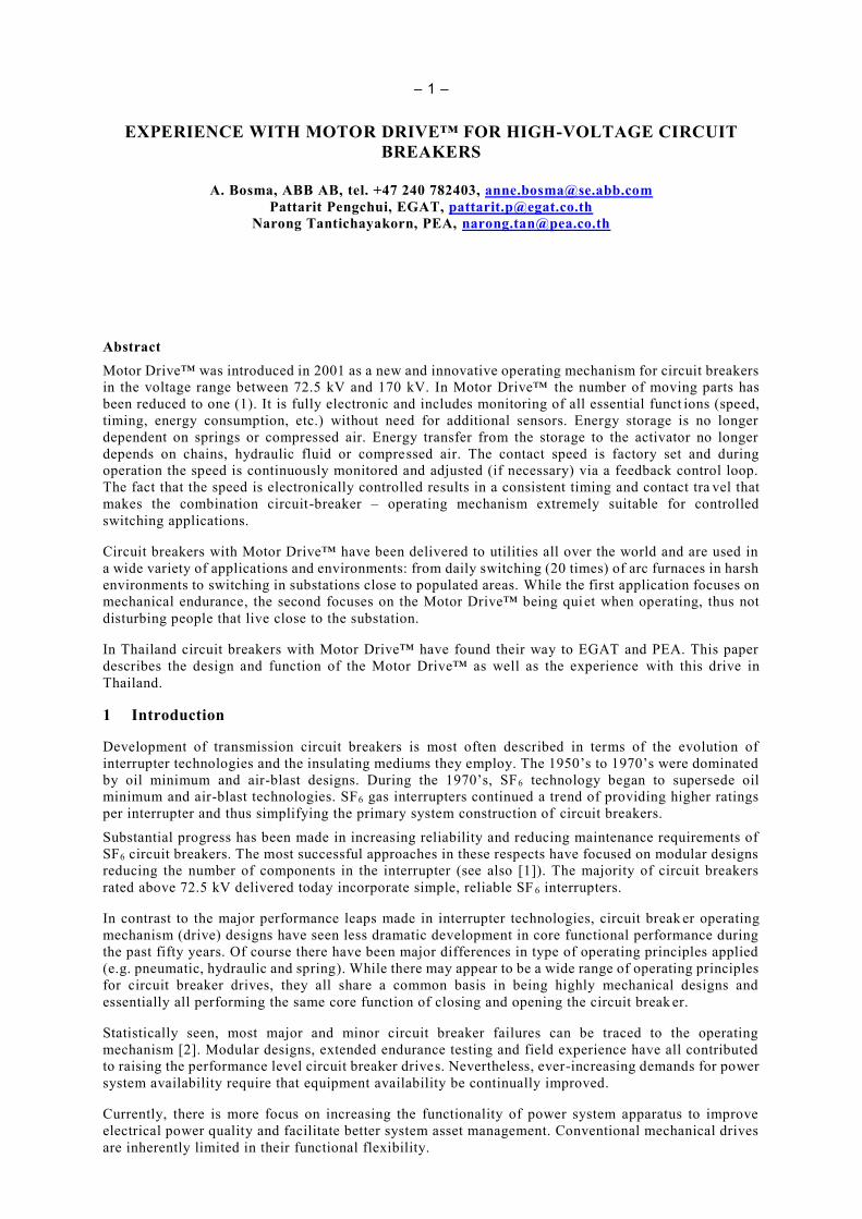
Motor Drive™ consists of a number of modules to perform such a function. The modules and their
connection is depicted in Figure 1.
Converter Capacitor Bank Charger
Control UnitMotor and
resolverI/O Unit
User
Interface
AC
DC
Figure 1 - Design of the Motor Drive™
In terms of the core drive functions described in section 2 the following units can be identified:
1. Energy Transmission: Motor and Resolver;
2. Energy Release: Converter and Control Unit;
3. Energy Storage: Capacitor Bank;
4. Energy Charging: Charger;
5. Control and Signaling: Input/Output (I/O) Unit.
The motor is fed from an energy buffer (a bank of electrolytic capacitors) through the converter unit.
The capacitor bank is charged by the charging unit, which also supplies power to the control and
input/output units. A microprocessor based control unit facilitates control of the operation speed and
condition monitoring. Access to the Motor Drive™ for all external user connections is via the
input/output unit.
The function of each individual unit is discussed further below.
3.2 Motor and Resolver
The motor replaces the conventional energy transmission (e.g. chains, hydraulic fluid, compressed air,
valves and pipes) and is the only moving part in the Motor Drive™. Having only one moving part means
there are no internal impacts or wearing components.
The motor (see Figure 2) is a three-phase, brushless, synchronous motor with permanent magnet rotor.
Since the motor must reach full torque in a very short amount of time in order to provide the proper
travel curve for a high-voltage circuit breaker, it has been specially adapted for such se rvice conditions.
– 5 –
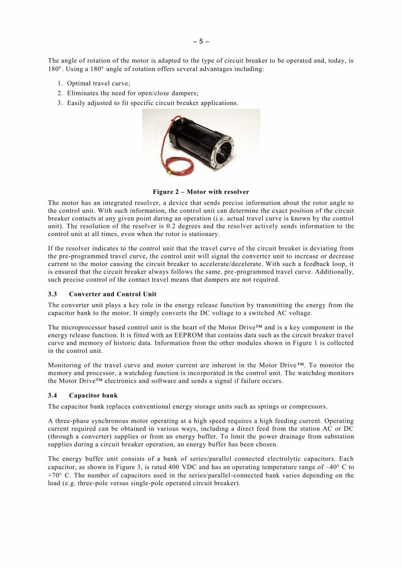
The angle of rotation of the motor is adapted to the type of circuit breaker to be operated and, today, is
180. Using a 180 angle of rotation offers several advantages including:
1. Optimal travel curve;
2. Eliminates the need for open/close dampers;
3. Easily adjusted to fit specific circuit breaker applications.
Figure 2 – Motor with resolver
The motor has an integrated resolver, a device that sends precise information about the rotor angle to
the control unit. With such information, the control unit can determine the exact position of the circuit
breaker contacts at any given point during an operation (i.e. actual travel curve is known by the control
unit). The resolution of the resolver is 0.2 degrees and the reso lver actively sends information to the
control unit at all times, even when the rotor is stationary.
If the resolver indicates to the control unit that the travel curve of the circuit breaker is deviating from
the pre-programmed travel curve, the control unit will signal the converte r unit to increase or decrease
current to the motor causing the circuit breaker to accelerate/decelerate. With such a feedback loop, it
is ensured that the circuit breaker always follows the same, pre -programmed travel curve. Additionally,
such precise control of the contact travel means that dampers are not required.
3.3 Converter and Control Unit
The converter unit plays a key role in the energy release function by transmitting the energy from the
capacitor bank to the motor. It simply converts the DC voltage to a switched AC voltage.
The microprocessor based control unit is the heart of the Motor Drive™ and is a key component in the
energy release function. It is fitted with an EEPROM that contains data such as the circuit breaker travel
curve and memory of historic data. Information from the other modules shown in Figure 1 is collected
in the control unit.
Monitoring of the travel curve and motor current are inherent in the Motor Drive ™. To monitor the
memory and processor, a watchdog function is incorporated in the control unit. The watchdog monitors
the Motor Drive™ electronics and software and sends a signal if failure occurs.
3.4 Capacitor bank
The capacitor bank replaces conventional energy storage units such as springs or compressors.
A three-phase synchronous motor operating at a high speed requires a high feeding current. Operating
current required can be obtained in various ways, including a direct feed from the station AC or DC
(through a converter) supplies or from an energy buffer. To limit the power drainage from substation
supplies during a circuit breaker operation, an energy buffer has been chosen.
The energy buffer unit consists of a bank of series/parallel connected electrolytic capacitors. Each
capacitor, as shown in Figure 3, is rated 400 VDC and has an operating temperature range of –40 C to
+70 C. The number of capacitors used in the series/parallel -connected bank varies depending on the
load (e.g. three-pole versus single-pole operated circuit breaker).

– 6 –
Figure 3 - Capacitor Unit
When fully discharged, it takes approximately three minutes to fully charge a capacitor unit, depending,
of course, on the size of the capacitor bank for a given application. Current drawn from the substation
auxiliary supply during charging is approximately 2 A. Not only is the current drawn during charging
considerably less than for conventional drives, but perhaps more importantly, there are no high
transients.
Energy buffering capacity is designed to meet the requirements for operating sequences specifi ed by
international standards [3], [4]. Thus, the energy buffer unit is capable of providing power to the motor
for a complete O – 0.3 s – CO or CO – 15 s – CO operating cycle.
The energy buffer unit is fitted with alarms indicating stored energy level. Further, it is possible to
monitor the energy buffer unit to ensure that each individual capacitor is working properly.
While the energy stored in the capacitors is continually replenished, the entire Motor Drive™, including
energy buffer unit and electronics but excluding heaters, draws a continuous load of less than 100 W.
3.5 Charger
The charger unit is used to charge the capacitor bank. It has redundant power supply inputs with the
main supply being AC and additional DC supply serving as back-up.
In the event that the main AC supply is lost, the charger automatically switches to the back-up DC supply
and sends an alarm to indicate supply failure. When the AC supply is restored, the charger unit will
automatically switch back to the main supply.
In the unlikely event that both main and back-up supplies are lost, it is possible to perform a pre-
programmed opening operation after which the circuit breaker is blocked from further operation. If such
an option is not desired, possibilities exist to achieve the same function as the mechanical trip of
conventional operating mechanisms, but in a very different way. If all supply power is lost, it is possible
to charge the Motor Drive™ using a car or truck battery and thus allow the necessary operations to
isolate the circuit breaker.
At each circuit breaker operation, power is drawn from the capacitor bank thereby decreasing the
voltage. The charger is then activated and the capacitor bank is recharged. Again, the current drawn
during such a charging operation is less than 2.0 A and there are no current surges on the AC or DC
supply.
3.6 Input/Output (I/O) Unit
Interface between the Motor Drive™ and the user is via the I/O unit (see Figure 4). The I/O unit sends
monitoring signals (i.e. energy charge level, charger supply status, watchdog, etc.) from the Motor
Drive™ to the user. Signals received from the control room (e.g. trip and close commands) are received
by the I/O unit and then forwarded to the control unit.

– 7 –
Mo
tor D
rive
Inte
rna
l Inte
rface
Use
r Inte
rface
Open
Close
CB open
CB closed
Energy level 1
Energy level 2
”Watchdog” fail”Watchdog” fail
O inhibitedCO inhibited
OCO inhibited
Counter impulse
CB openCB closed
SF6 block autotrip selected
Power supply autotrip selected
SF6 block autotrip jumper
Power supply autotrip jumper
SF6 block
Open 1 and 2
Close 1 and 2
Power supply supervision
Figure 4 - Input/Output Unit
Other functions interfaced via the I/O unit include:
- SF6 monitoring for purposes of blocking operation on low SF 6 density;
- Operating panel with local/remote and open/close switches, indication lamps, operation counter,
etc.;
- Auxiliary relays (Auxiliary contacts have been replaced by bi-stable auxiliary relays activated
once the rotor has reached a specified angle, depending on whether they are “a” or “b” contacts.);
- Dual trip command inputs;
- Dual close command inputs;
- Continuous trip signal block.
4 CONDITION MONITORING
4.1 On-line Condition Monitoring of Conventional Drives
On-line condition monitoring has attracted much attention as a means to further enhance circuit breaker
availability and asset management. Condition monitoring does not necessarily increase reliability, but
may increase availability by giving an early warning that failure is imminent and allowing maintenance
to be based on actual circuit breaker service.
It is, however, generally recognized that the effectiveness of monitoring the complex mechanical system
of a transmission circuit breaker is limited by the following factors.
1. The failure modes in many mechanical systems are sudden, with little or no preceding indicators.
Furthermore, the inherent complexity of the mechanical system is such that, even if a deviation
in a performance parameter is detected, i t can be difficult to determine the root cause without
conducting a detailed intrusive inspection of the circuit breaker;
2. There are limitations in the cost and type of sensors for measuring key parameters;
3. The reliability of monitors and sensors is sometimes less than for the circuit breaker itself.
4. Most of the relevant monitoring data can only be obtained during the dynamic operation of the
circuit breaker, which for many circuit breakers is infrequent and thus further limits the ability
to provide “early warning” of a problem.
4.2 On-line monitoring of Motor Drive™
Due to the nature of the Motor Drive™ design, condition monitoring is inherent. Motor Drive™ has an
extensive array of data that can be retrieved either locally from the control unit or remotely vi a a modem.
Monitored parameters include:
- Contact travel;
– 8 –
- Opening and closing times (measured from command impulse to a defined rotor angle);
- Energy consumption during operation;
- Energy buffer discharging characteristics;
- Motor current and torque;
- Temperature of the control unit;
- Watchdog status.
All data is stored at the time of the most recent operation and is then available for download.
Additional to the monitoring functions described above, it is possible to operate the circuit breaker a
few mm every day to check the status of the entire chain (i.e. charger, control, motor, reso lver and
energy buffer units). This so-called micro motion does not take more than a few ms and gives immediate
information about the status of both the Motor Drive™ and the circuit breaker. In other words: it is
possible to know in advance if the circuit breaker and drive are ready for operation or not, regardless of
the frequency of operation of the circuit breaker. With conventional drives, such monitoring possibil ities
do not exist.
5 EXPERIENCE WITH MOTOR DRIVE™ IN THE FIELD
5.1 General
Since the introduction in 2001 several hundred live tank circuit breakers have been delivered with three-
pole and single-pole operated Motor Drive™. Application ranges from three-pole operated line circuit
breakers that switch infrequently to single-pole operated circuit breakers used for controlled switching.
Controlled switching is often used when circuit breakers are used to energize of de -energize reactive
loads such as capacitor banks, shunt reactors or no-load transformers. One particular application where
Motor Drive™ is used, is switching of arc furnace transformers in a steel mill in Mexico, where the
operating frequency is approximately 20 times daily. Even here controlled switching is used to reduce
the inrush current when energizing the arc furnace transformer.
The environments of the circuit breakers supplied with Motor Drive™ range from arctic climates
(Sweden, Finland) to tropical climates (Thailand, Chile, Venezuela).
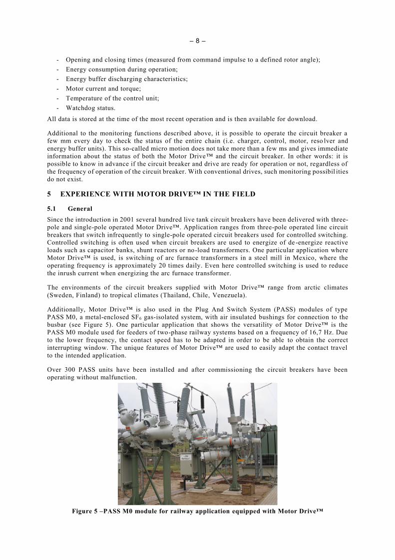
Additionally, Motor Drive™ is also used in the Plug And Switch System (PASS) modules of type
PASS M0, a metal-enclosed SF6 gas-isolated system, with air insulated bushings for connection to the
busbar (see Figure 5). One particular application that shows the versatility of Motor Drive™ is the
PASS M0 module used for feeders of two-phase railway systems based on a frequency of 16,7 Hz. Due
to the lower frequency, the contact speed has to be adapted in order to be able to obtain the correct
interrupting window. The unique features of Motor Drive™ are used to easily adapt the contact travel
to the intended application.
Over 300 PASS units have been installed and after commissioning the circuit breakers have been
operating without malfunction.
Figure 5 –PASS M0 module for railway application equipped with Motor Drive™
– 9 –
5.2 Experience with Motor Drive™ in Thailand
5.2.1 EGAT, Thailand
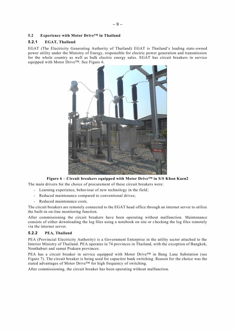
EGAT (The Electricity Generating Authority of Thailand) EGAT is Thailand’s leading state-owned
power utility under the Ministry of Energy, responsible for electric power generation and transmission
for the whole country as well as bulk electric energy sales. EGAT has circuit breakers in service
equipped with Motor Drive™. See Figure 6.
Figure 6 – Circuit breakers equipped with Motor Drive™ in S/S Khon Kaen2
The main drivers for the choice of procurement of these circuit breakers were:
- Learning experience, behaviour of new technology in the field ;
- Reduced maintenance compared to conventional drives;
- Reduced maintenance costs.
The circuit breakers are remotely connected to the EGAT head office through an internet server to utilize
the built-in on-line monitoring function.
After commissioning the circuit breakers have been operating without malfunction. Maintenance
consists of either downloading the log files using a notebook on site or c hecking the log files remotely
via the internet server.
5.2.2 PEA, Thailand
PEA (Provincial Electricity Authority) is a Government Enterprise in the utility sector attached to the
Interior Ministry of Thailand. PEA operates in 74 provinces in Thailand, with the exception of Bangkok,
Nonthaburi and samut Prakarn provinces.
PEA has a circuit breaker in service equipped with Motor Drive™ in Bang Lane Substation (see
Figure 7). The circuit breaker is being used for capacitor bank switching. Reason for the choice was the
stated advantages of Motor Drive™ for high frequency of switching.
After commissioning, the circuit breaker has been operating without malfunction.

– 10 –
Figure 7 – Circuit breaker equipped with Motor Drive™ in S/S Bang Lane
5.3 Summary of experience
Overall experience of operation of circuit breakers equipped with Motor Drive™ has been excellent.
The use of a fully electronic drive to operate a circuit breaker at high -voltage requires different skills
than a conventional drive. When discussing circuit breakers equipped with Motor Drive™ concerns are
raised on the following issues:
- Software/firmware updates: should be kept to a minimum, to comply with the low maintenance
frequency. On the other hand, software/firmware updates can be done remotely, without the need
to take the circuit breaker out of service;
- Hardware: Electronics are undergoing rapid changes compared to the circuit breaker technology
and the question has been raised how the manufacturer will address the availability of spare parts
for the expected life of the circuit breaker (25 – 30 years). The hardware is designed for the
lifetime of the circuit breaker and in case a module needs to be exchanged, compatible modules
are available;
- Maintenance and testing: Many utilities use time based management and inspect the circuit
breaker with its operating mechanism at regular intervals. On occasion timing tests are performed
to see that there is no unexpected deviation from the operating limits specified by the
manufacturer. In the case of a circuit breaker equipped with Motor Drive™ there is no need for
maintenance, as the drive is equipped with inherent monitoring features (see 4.2). During each
operation the contact travel follows a pre-programmed curve and any deviation is compensated
for by the feedback loop described in 3.2;
- Future: At the time Motor Drive™ first appeared on the market, IEC 61850 was still under
development. Nowadays the requirements for communication of substation equipment with the
substation control have a solid base and Motor Drive™ will soon be available with IEC 61850
communication.

– 11 –
6 REFERENCES
[1] BOSMA, A. and SCHREURS, E., Cost optimization versus function and reliability of HVAC
circuit-breakers, CIGRÉ Session 2000, 13-102
[2] CIGRÉ Technical Brochure 510: Final Report of the 2004 – 2007 International Enquiry on Reliability of
High Voltage Equipment, CIGRÉ, Paris, 2012, ISBN: 978- 2- 85873- 202-9
[3] IEC 62271-100, 2012: High-voltage switchgear and controlgear – Part 100: Alternating-current
circuit-breakers
[4] IEEE Std C37.04-1999: IEEE Standard Rating Structure for AC High-Voltage Circuit Breakers
Keywords
Circuit breaker, Motor Drive™, operating mechanism, experience