experience gained at the ural turbine works with...
TRANSCRIPT

ISSN 0040�6015, Thermal Engineering, 2013, Vol. 60, No. 8, pp. 541–547. © Pleiades Publishing, Inc., 2013.Original Russian Text © A.E. Valamin, A.Yu. Kultyshev, A.A. Gol’dberg, T.L. Shibaev, H.C. Paneque Aguilera, 2013, published in Teploenergetika.
541
Recent years have seen ongoing modernization andreplacement of existing equipment items by new moreadvanced ones in the electric power industry of Russiaand CIS countries. This is primarily due to the factthat more than 60% of high�temperature thermalpower equipment, such as boiler houses and steam tur�bine units (STUs) installed at cogeneration stationsand district power stations (referred to henceforth asthermal power stations, TPSs) have worked out its ser�vice life.
Low tariffs for energy carriers and long periods oftime for which investments in new construction arepaid back are factors that compelled TPS owners, aswell as the governments of Russia and other countriesto take active efforts aimed at retrofitting the existingpower stations.
Indeed, retrofitting or modernization is an optionthat makes it possible to obtain considerable saving ofcapital investments as compared with construction ofnew or expansion of existing TPSs. If we take the totalcosts for constructing a new cogeneration station orexpanding an already existing one as 100%, then,according to the data of [1], the distribution of costsamong the individual parts of such a project will be asfollows: up to 40% for procurement of new equip�ment, up to 50% for civil construction works, up to15% for erection works, and 2–3% for the other works.
Hence, by using the existing buildings, pedestalsfor equipment, crane facilities and replacing onlyobsolete equipment items by more advanced newones, it is possible to safe around 40–50% of the totalsum of money owing to exclusion of civil constructionworks alone taking into account some additional costsfor dismantling the equipment that is subject toreplacement.
Retrofitting and modernization are presentlyimplemented in different ways: from partial replace�ment of assemblies the service life of which cannot beextended to full replacement of power unit equipment.
The Ural Turbine Works (UTZ) participates inactivities concerned with modernizing, retrofitting,and renovating STUs produced by UTZ and by othermanufacturers, on the territory of Russia and abroad.In our opinion, projects of retrofitting STUs in theexisting turbine buildings of TPSs with retaining theirdimensions and the majority of building structures,including the crane facility and with the maximallypossible use of the existing turbine unit pedestal are themost interesting ones but requiring much effort fortheir development.
In this article, only a few TPS retrofitting projectsdeveloped with participation of the Ural TurbineWorks are described.
The cogeneration station of the Ural CarriageWorks was the first facility retrofitted with participa�tion of UTZ [2]. The pedestal, which was constructedin the 1930s, supported an AT�25�2 two�cylinder tur�bine produced by the Leningrad Metal Works (LMZ)and a T2�25�2 generator produced by the ElektrosilaWorks. The actual state of the pedestal was examined,and it was recognized from the examination resultsthat a new turbine set can be installed on this pedestal.After the overground structure of the pedestal in theturbine part and the upper plate in the generator parthad been partially dismantled, and the dismantledcomponents had been replaced by new ones, it becamepossible to install a new turbine set consisting of aPT�30/35�90/10�5 single�cylinder turbine producedby UTZ and a TFP�25�2U3 air�cooled generator pro�
Experience Gained at the Ural Turbine Works with Retrofitting Steam Turbine Units for Thermal Power Stations
A. E. Valamina, A. Yu. Kultysheva, b, A. A. Gol’dberga, T. L. Shibaeva, and H. C. Paneque Aguileraa
a Ural Turbine Works, ul. Frontovykh Brigad 18, Yekaterinburg, 620017 Russiab Ural Federal University, ul. Mira 19, Yekaterinburg, 620002 Russia
Abstract—Examples of projects on retrofitting, modernizing, and renovating steam turbine units at thermalpower stations implemented with participation of the Ural Turbine Works are given. Advanced constructionand layout solutions were used in implementing these projects both on the territory of Russia and abroad.
Keywords: steam turbine unit, modernization, retrofitting, pedestal, layout, horizontal delivery�water heater,condenser, generator
DOI: 10.1134/S0040601513080132
STEAM�TURBINE, GAS�TURBINE, AND COMBINED�CYCLE PLANTS AND THEIR AUXILIARY EQUIPMENT

542
THERMAL ENGINEERING Vol. 60 No. 8 2013
VALAMIN et al.
duced by Elektrosila. The modified pedestal is shownin Fig. 1.
The remaining equipment was arranged within theconfines of the old turbine building, with due regard ofthe four delivery�water heaters remained at their pre�vious places, which had been replaced by new ones notlong before the retrofitting.
In connection with possible inundation, limitationswere imposed on the works in the floor of the condensercompartment, due to which design solutions wereadopted that did not require making significant sumpsor hydraulic locks in the floor. Retaining the elements ofoperating equipment and process lines adjacent to thenew turbine unit was also a challenging task.
The cogeneration station of the Siberian ChemicalCombine in the city of Seversk, in which the entirethermal power equipment installed in the turbinebuilding had to be retrofitted, was one of the most dif�
ficult facilities for UTZ. The new Tp�100/110�90 tur�bine was installed instead of the VKT�100�90 turbine(produced by the Kharkov Turbine Works), which hadworked out its service life, and the old generator had tobe replaced by a TF�110�2UZ air�cooled generatorproduced by NPO ELSIB. The new (also two�cylin�der) Tp�100/110�90 turbine unit with one exhausthood and one condenser differed essentially in itsdesign from the dismantled turbine unit, which had alow�pressure cylinder (LPC) with two exhaust hoodsand two condensers.
Very tight constraints were imposed on the STUcivil construction part in that project: the turbine unitpedestal—a reinforced�concrete wall structure withextremely tight conditions inside the foundation—hadto be retained almost completely (Fig. 2). According tothe contract, the new STU was fitted with two PSG�2200horizontal delivery�water heaters (HDWHs) designedfor an increased pressure of network water. To mini�
Support of the generatorbearing
Support of the turbinefront legs
Support of the turbinefront bearing Support of the
generator stator
Support of the turbine exhaust part
+7.000+6.350
7000
+2.300+1.100
4600
1625
0.000
–1.000
–3.500
123
Fig. 1. Pedestal of the PT�30/35�90/10�5 steam turbine unit. (1) Overall dimensions of the new pedestal, (2) overall dimensionsof the existing pedestal retained during the retrofitting, and (3) butt jointing of the new and existing pedestals.

THERMAL ENGINEERING Vol. 60 No. 8 2013
EXPERIENCE GAINED AT THE URAL TURBINE WORKS WITH RETROFITTING 543
mize the amount of civil construction works and tomaximally retain the pedestal, its retrofitting wasreduced to modifying only those elements that couldnot be retained in their initial form. For example, ininstalling the HDWH No. 2 under the generator insidethe foundation, some amounts of concrete were cutaway in the pedestal walls with leaving the minimal gapbetween the concrete and equipment. The HDWHNo. 1 was installed into the pedestal opening in whichone of the condensers was located previously. The ped�estal’s upper structure was modified only in the part ofinstalling new pedestal frames and in making new wellsfor anchor studs. Figure 3 shows how the HDWHs arearranged within the pedestal overall dimensions. Inaddition, the crossover pipes of the high� and interme�diate�pressure cylinders (HPC and IPC) and thesteam extractions to the high� and low�pressure heat�ers were routed so as to simultaneously fulfill therequirements for self�compensation, strength, conve�nience of erection, and maximal retaining of the ped�estal structure.
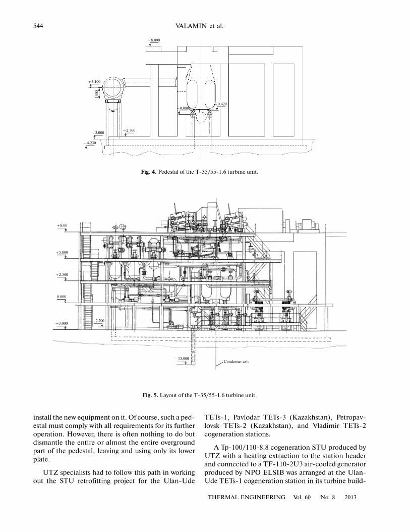
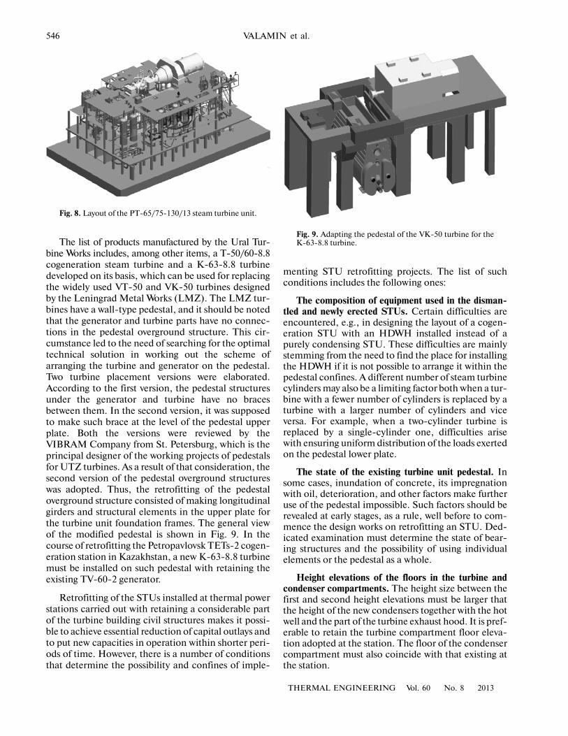
The Perm TETs�14 cogeneration station was afacility the retrofitting of which involved difficulties inimplementing layout and civil construction solutions.According to the project, it was necessary to install aT�35/55�1.6 bottom steam turbine [3] operating on
steam supplied from the process header. It should benoted that the R�100�12.8 turbine, which had been takenout from operation for a long period of time due to thelack of steam consumers, also began to operate on thisheader after the retrofitting. As a result, the station poweroutput increased by 135 MW. The new T�35/55�1.6 tur�bine was installed on the place of the T�50�90�2 tur�bine, which had worked out its service life.
As in the previous example, retaining of the turbineunit pedestal to the maximum possible extent was themost challenging requirement in designing the STU.In addition, the customer requested to leave the exist�ing generator on its original place even in the course ofretrofitting and to use it afterwards with the new tur�bine. Thus, UTZ specialists had to develop an STUproject with a bottom turbine with due regard of theabove�mentioned requirements.
Since the new turbine was installed on the existingpedestal of the two�cylinder turbine, the main difficul�ties were encountered in modifying the pedestal’soverground structure. The pedestal’s part under thegenerator had to be retained fully intact because thegenerator had to remain on its original place. Thescope of supply included, along with a T�35/55�1.6turbine, a PSG�1300 horizontal delivery�water heater.A few versions of arranging the PSG�1300 apparatuswere elaborated, after which it was decided to install iton the pedestal before the turbine. The use of such ver�sion made it possible to bring the load applied to theturbine unit pedestal lower plate to its design level. Asa result, the lower plate, the pedestal’s generator part,and the columns in the pedestal’s turbine part werefully retained. A new pedestal upper plate directlyconnected with the foundation frames of the new tur�bine was made in the turbine part. Figure 4 shows thegeneral view of the turbine unit pedestal, and Fig. 5shows the STU layout.
As was already mentioned, a customer whose STUis to be retrofitted wishes to use the pedestal of thereplaced turbine unit or only the turbine pedestal to
Fig. 2. Pedestal of the Tp�100/110�90 steam turbine unit.
Fig. 3. Layout of the Tp�100/110�90 steam turbine unit.
544
THERMAL ENGINEERING Vol. 60 No. 8 2013
VALAMIN et al.
install the new equipment on it. Of course, such a ped�estal must comply with all requirements for its furtheroperation. However, there is often nothing to do butdismantle the entire or almost the entire overgroundpart of the pedestal, leaving and using only its lowerplate.
UTZ specialists had to follow this path in workingout the STU retrofitting project for the Ulan�Ude
TETs�1, Pavlodar TETs�3 (Kazakhstan), Petropav�lovsk TETs�2 (Kazakhstan), and Vladimir TETs�2cogeneration stations.
A Tp�100/110�8.8 cogeneration STU produced byUTZ with a heating extraction to the station headerand connected to a TF�110�2U3 air�cooled generatorproduced by NPO ELSIB was arranged at the Ulan�Ude TETs�1 cogeneration station in its turbine build�
+3.100
1400
–3.000
–4.230
–2.700
–0.080+0.420
+8.000
Fig. 4. Pedestal of the T�35/55�1.6 turbine unit.
+8.00
+5.000
+2.500
0.000
–3.000–2.700
–15.000Condenser axis
Fig. 5. Layout of the T�35/55�1.6 turbine unit.

THERMAL ENGINEERING Vol. 60 No. 8 2013
EXPERIENCE GAINED AT THE URAL TURBINE WORKS WITH RETROFITTING 545
ing on the place of the fire�damaged VK�100�6 STUconnected to a TVF�100�2 hydrogen�cooled generator.
Examinations and geological surveys were carriedout, after which the customer decided that only theturbine unit pedestal’s lower plate and the reinforced�concrete piers in the cellar compartment (with par�tially replacing the floor slabs of the condenser com�partment) had to be retained of the existing buildingstructures. Workers of a dedicated organization cut thepedestal columns almost flush with the upper surfaceof the pedestal lower plate with the use of special tech�nology. The external view of the reinforced�concretestructure remained after this operation is shown in Fig. 6.Requirement specifications were developed at UTZfor the pedestal and floors with the use of the founda�tion lower plate and the structures that remained in the
turbine building. The columns and the pedestal upperstructure were made in accordance with the configura�tion required for installing the Tp�100/110�8.8 turbineand the TF�110�2U3 generator. The pedestal design isshown in Fig. 7a. Not only did the cogeneration sta�tion’s power output reach its pre�accident level as aresult of the accomplished retrofitting, but it evenexceeded its original capacity, and the station receiveda modern STU.
In connection with the fact that the PT�60 turbine(produced at the Czech Republic) installed at the Pav�lodar TETs�3 cogeneration station had become physi�cally worn, UTZ supplied a PT�65/75�12.8/1.3/13cogeneration steam turbine with process and heatingextractions to the station headers and with a newTF�63�2U3 generator. As at the Ulan�Ude TETs�1cogeneration station, the pedestal upper structure andpart of columns to the floor level in the condensercompartment were dismantled at the Pavlodar TETs�3cogeneration station. However, in contrast to the pre�vious project, the pedestal lower plate was strength�ened by 500 mm in height. Elaborations of the pedes�tal lower plate were carried out in order to retain thecentral cable channel, which housed electrical cables,because it was not possible not only to shift, but evento disconnect them during the retrofitting. Apart fromthe pedestal lower plate, the electrically driven feed�water pumps and the station boiler unit were retainedon their places. This circumstance added difficulty tothe work on developing the STU layout, but made itpossible to save a considerable sum of money in retro�fitting the cogeneration station turbine building. Thedrawing of the turbine unit pedestal is shown in Fig. 7b,and the STU layout is shown in Fig. 8.
Fig. 6. External view of the existing lower plate.
(а) (b)
Fig. 7. Pedestals of the Tp�100/110�8.8 steam turbine unit installed at the TETs�1 cogeneration station in the Ulan�Ude city (a)and of the PT�65/75�130/13 steam turbine unit (b).
546
THERMAL ENGINEERING Vol. 60 No. 8 2013
VALAMIN et al.
The list of products manufactured by the Ural Tur�bine Works includes, among other items, a T�50/60�8.8cogeneration steam turbine and a K�63�8.8 turbinedeveloped on its basis, which can be used for replacingthe widely used VT�50 and VK�50 turbines designedby the Leningrad Metal Works (LMZ). The LMZ tur�bines have a wall�type pedestal, and it should be notedthat the generator and turbine parts have no connec�tions in the pedestal overground structure. This cir�cumstance led to the need of searching for the optimaltechnical solution in working out the scheme ofarranging the turbine and generator on the pedestal.Two turbine placement versions were elaborated.According to the first version, the pedestal structuresunder the generator and turbine have no bracesbetween them. In the second version, it was supposedto make such brace at the level of the pedestal upperplate. Both the versions were reviewed by theVIBRAM Company from St. Petersburg, which is theprincipal designer of the working projects of pedestalsfor UTZ turbines. As a result of that consideration, thesecond version of the pedestal overground structureswas adopted. Thus, the retrofitting of the pedestaloverground structure consisted of making longitudinalgirders and structural elements in the upper plate forthe turbine unit foundation frames. The general viewof the modified pedestal is shown in Fig. 9. In thecourse of retrofitting the Petropavlovsk TETs�2 cogen�eration station in Kazakhstan, a new K�63�8.8 turbinemust be installed on such pedestal with retaining theexisting TV�60�2 generator.
Retrofitting of the STUs installed at thermal powerstations carried out with retaining a considerable partof the turbine building civil structures makes it possi�ble to achieve essential reduction of capital outlays andto put new capacities in operation within shorter peri�ods of time. However, there is a number of conditionsthat determine the possibility and confines of imple�
menting STU retrofitting projects. The list of suchconditions includes the following ones:
The composition of equipment used in the disman�tled and newly erected STUs. Certain difficulties areencountered, e.g., in designing the layout of a cogen�eration STU with an HDWH installed instead of apurely condensing STU. These difficulties are mainlystemming from the need to find the place for installingthe HDWH if it is not possible to arrange it within thepedestal confines. A different number of steam turbinecylinders may also be a limiting factor both when a tur�bine with a fewer number of cylinders is replaced by aturbine with a larger number of cylinders and viceversa. For example, when a two�cylinder turbine isreplaced by a single�cylinder one, difficulties arisewith ensuring uniform distribution of the loads exertedon the pedestal lower plate.
The state of the existing turbine unit pedestal. Insome cases, inundation of concrete, its impregnationwith oil, deterioration, and other factors make furtheruse of the pedestal impossible. Such factors should berevealed at early stages, as a rule, well before to com�mence the design works on retrofitting an STU. Ded�icated examination must determine the state of bear�ing structures and the possibility of using individualelements or the pedestal as a whole.
Height elevations of the floors in the turbine andcondenser compartments. The height size between thefirst and second height elevations must be larger thatthe height of the new condensers together with the hotwell and the part of the turbine exhaust hood. It is pref�erable to retain the turbine compartment floor eleva�tion adopted at the station. The floor of the condensercompartment must also coincide with that existing atthe station.
Fig. 8. Layout of the PT�65/75�130/13 steam turbine unit.
Fig. 9. Adapting the pedestal of the VK�50 turbine for theK�63�8.8 turbine.

THERMAL ENGINEERING Vol. 60 No. 8 2013
EXPERIENCE GAINED AT THE URAL TURBINE WORKS WITH RETROFITTING 547
The existing crane facilities should be considered indifferent aspects. First, the bridge crane lifting capac�ity must be sufficient for using it in the course of erec�tion works and during operation for lifting the heaviestcomponents of the new STU, such as the low�pressurecylinder’s (LPC) upper half and the casing of the high�pressure heater (HPH). The stator of the new genera�tor can be installed, if necessary, using a dedicatedtechnology. Second, the crane hook lifting heightabove the turbine compartment floor must be suffi�cient for lifting bulky elements of the new STU (theLPC upper half and the HPH casing) and movingthem over the turbine hall during operation.
Performance of earth moving works in the turbinebuildings of some stations is impossible or difficult dueto a number of factors, for example, due to the factthat the hydraulic locks and sumps are made below thefloor height elevations of the condenser compartment
or cellar. Each case of such sort for a particular facilitymust be addressed individually.
It can be seen from the examples presented abovethat the layout and civil construction solutionsadopted in retrofitting or modernizing STUs at ther�mal power stations are strictly individual rather thantypical in nature.
REFERENCES
1. V. Ya. Ryzhkin, Thermal Power Stations (Energiya,Moscow, 1976) [in Russian].
2. G. D. Barinberg, Yu. M. Brodov, A. A. Gol’dberg, et al.,Steam Turbines and Turbine Units Produced by the UralTurbine Works, Ed. by Yu. M. Brodov and V. V. Kortenko(Aprio, Yekaterinburg, 2010) [in Russian].
3. G. D. Barinberg, A. E. Valamin, and Yu. A. Sakhnin,“Bottom steam turbines of the Ural Turbine Works,”Therm. Eng., No. 8, 665 (2008).
Translated by V. Filatov