expansion joints sm meg pt railwaj sts types · uni 4916 - en 10025 8 anchor system cl. 8.8...
TRANSCRIPT
EXPANSION JOINTSSM MEG PT RAILWAJ STS TYPES

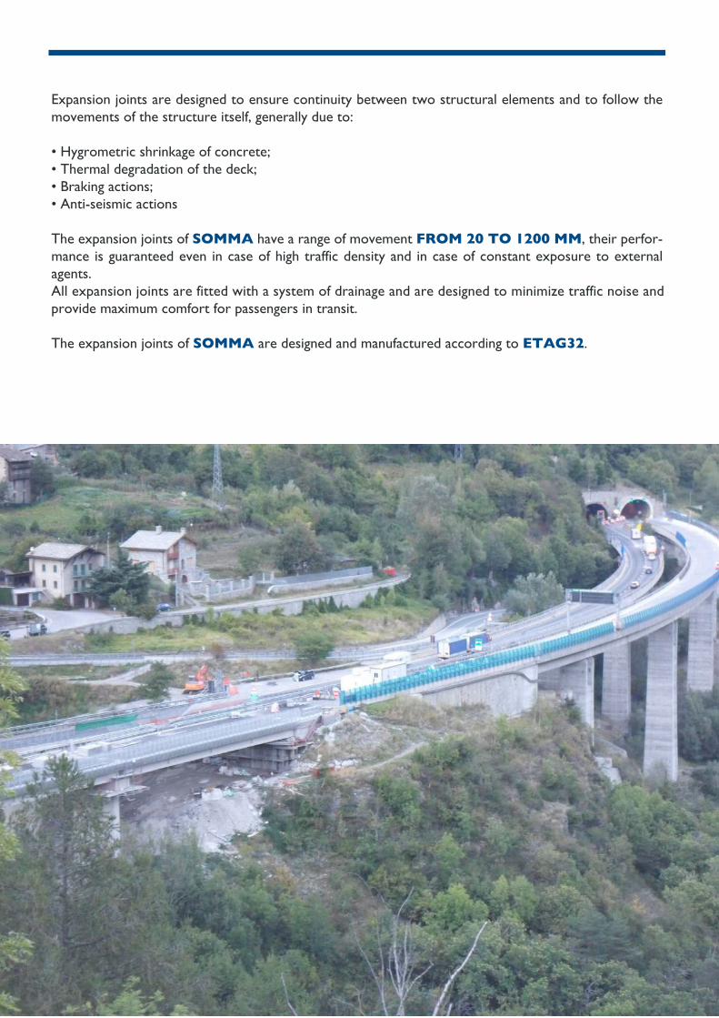
Expansion joints are designed to ensure continuity between two structural elements and to follow the movements of the structure itself, generally due to:
• Hygrometric shrinkage of concrete; • Thermal degradation of the deck; • Braking actions;• Anti-seismic actions The expansion joints of SOMMA have a range of movement FROM 20 TO 1200 MM, their perfor-mance is guaranteed even in case of high traffic density and in case of constant exposure to external agents.All expansion joints are fitted with a system of drainage and are designed to minimize traffic noise andprovide maximum comfort for passengers in transit.
The expansion joints of SOMMA are designed and manufactured according to ETAG32.

REINFORCED RUBBER JOINTS – SMALL MOVEMENTS
JOINT SMF 100S
JOINT SMF 50
SMF
They consist of steel side plates and one or more central steel bridge plates, vulcanised with deformable rubber elements, arranged so that, when the joint is cut vertically, at least one reinforcement element is always encountered.
The expansion joints are manufactured according to ETAG32.
The joint panel is supplied with rubber flashing for water collection and with the fixing system, consisting of anchor bolts, washers and self-locking nuts.
It has a water drainage system thanks to the insertion of an aluminium C profile.
UP TO +/- 25
UP TO +/- 50

MATERIALS
POS OBJECT MATERIAL STANDARD
1 DRAINAGE SYSTEM ALUMINIUM UNI9006/1
2 ANCHOR PLATE S275
3 RUBBER PANEL ELASTOMER 60SH
4 CONTRAST WASHER S235 JR
S235 JR5 DISTRIBUTION WASHER
6
7
ELASTOMER
M12 CLASSE 6S
M12X165 CL.8.8
8
ANCHOR SYSTEM
LOCKNUT
FLASHING
EN 1337
EN 1337
EN 10025
EN 10025
EN 10025
EN 20898
EN 20898

EXPANSION JOINTS SM FOR SMALL AND MEDIUM MOVEMENTS
SM
They consist of steel side plates and one or more central steel bridge plates, vulcanised with deformable rubber elements, arranged so that, when the joint is cut vertically, at least one reinforcement element is always encountered.
The xpansion joints are manufactured according to ETAG32.
The joint panel is supplied with rubber flashing for water collection and with the fixing system, consisting of anchor bolts, washers and self-locking nuts. It has a water drainage system thanks to the insertion of an aluminium C profile.

MATERIALS AND TYPES
POS OBJECT MATERIAL STANDARD
1 MIXTURE THIKNESS HIGH STRENGHTREAOPLASTIC CONCRETE
2 EPOXY STICK
3 FLASHING HYPALON
4 MIXTURE FOR ANCHOR FIXING
5 DRAINAGE SYSTEM ALLUMINIUM
EPOXY6 ELASTIC SEALANT
ELASTOMER 60 SH - 2235JR
UNI 9006/1
7 MAT
CL8.88 ANCHORING SYSTEM
S275 ZN
EN 20898
EN 1337/EN 10025
EN 1337
TYPE MOVEMENT H (mm) MEDIUM GAP (mm)L (mm) ANCHOR
SM50 ± 25 MM
± 32,5 MM
± 40 MM
± 55 MM
SM65
SM80
SM110
37
40
45
240
266
352
46 356
9 OVAL WASHER
CL 8
S235 GALVANIZED EN 10025
EN 2089810 LOCKNUT
11 LAYER
12 BINDER
13 DECK WATERPROOFING
35
45
55
70
M14x200
M14x200
M16x200
M18x200
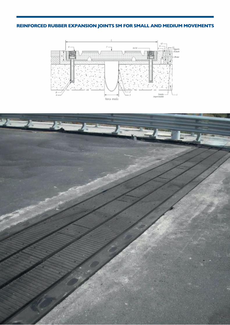
REINFORCED RUBBER EXPANSION JOINTS SM FOR SMALL AND MEDIUM MOVEMENTS

MATERIALS AND TYPES
SM 120 ± 60 MM 55 580 80 M18X200
SM 200 ± 100 MM 78 711 110 M20X200
SM 250 ± 125 MM 98 892 145 M22X250
SM 350 ± 175 MM 128 1198 195 M27X250
TYPE MOVEMENT H (mm) MEDIUM GAP (mm)L (mm) ANCHOR
POS OBJECT MATERIAL STANDARD
1 MIXTURE THIKNESS HIGH STRENGHTREAOPLASTIC CONCRETE
2 EPOXY STICK
3 FLASHING HYPALON
4 MIXTURE FOR ANCHOR FIXING
5 DRAINAGE SYSTEM ALLUMINIUM
EPOXY6 ELASTIC SEALANT
ELASTOMER 60 SH - 2235JR
UNI 9006/1
7 MAT
CL8.88 ANCHORING SYSTEM
S275 ZN
EN 20898
EN 1337/EN 10025
EN 1337
9 OVAL WASHER
CL 8
S235 GALVANIZED EN 10025
EN 2089810 LOCKNUT
11 LAYER
12 BINDER
13 DECK WATERPROOFING
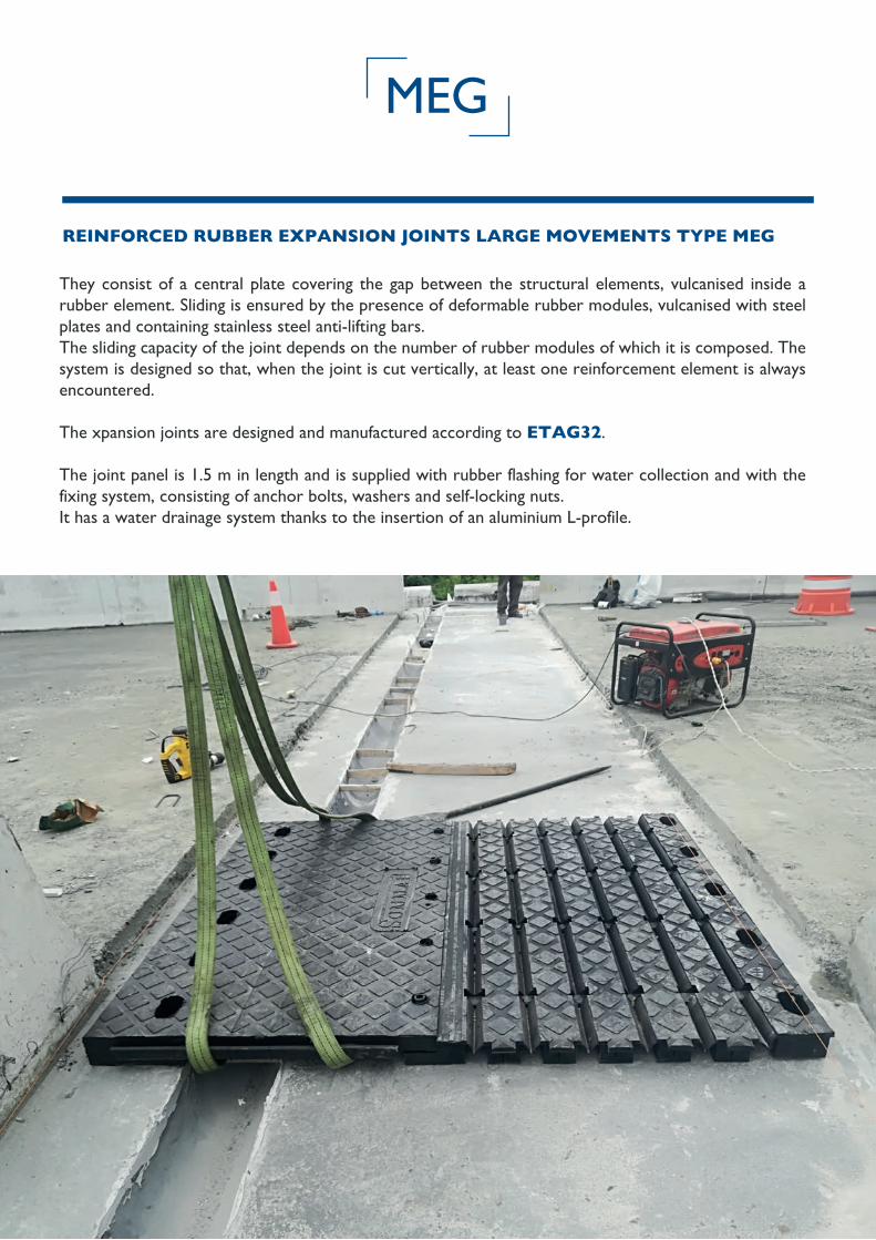
They consist of a central plate covering the gap between the structural elements, vulcanised inside a rubber element. Sliding is ensured by the presence of deformable rubber modules, vulcanised with steel plates and containing stainless steel anti-lifting bars.The sliding capacity of the joint depends on the number of rubber modules of which it is composed. The system is designed so that, when the joint is cut vertically, at least one reinforcement element is always encountered.
The xpansion joints are designed and manufactured according to ETAG32.
The joint panel is 1.5 m in length and is supplied with rubber flashing for water collection and with the fixing system, consisting of anchor bolts, washers and self-locking nuts. It has a water drainage system thanks to the insertion of an aluminium L-profile.
REINFORCED RUBBER EXPANSION JOINTS LARGE MOVEMENTS TYPE MEG
MEG

UP TO +/-320
REINFORCED RUBBER EXPANSION JOINTS LARGE MOVEMENTS TYPE MEG
UP TO +/-600

MATERIALS AND TYPES
MEG 720 ± 360 MM 85 2390 380 M24X250
MEG 800 ± 400 MM 85 2630 420 M24X250
MEG 900 ± 450 MM 85 2870 470 M24X250
MEG 1000 ± 500 MM 85 3250 520 M24X250
MEG 1100 ± 550 MM 85 3490 570 M24X250
MEG 1200 ± 600 MM 85 3730 620 M24X250
1
2
3 EN 1337
4
5 UNI 9006/1
6
7EN 1337 - EN 10025EN 10025 - EN 10088
8 EN 20898
9 EN 10025
10 EN 20898
11
TYPE MOVEMENT H (mm) MEDIUM GAP (mm)L (mm) ANCHOR
POS OBJECT MATERIAL STANDARD
MIXTURE THIKNESS HIGH STRENGHTREAOPLASTIC CONCRETE
EPOXY STICK
FLASHING HYPALON
EPOXY RESINMIXTURE FOR ANCHOR FIXING
DRAINAGE SYSTEM ALLUMINIUM
EPOXYELASTIC SEALANT
ELASTOMER 60 SH - 2235JRMAT
CL8.8ANCHORING SYSTEM
OVAL WASHER
CL 8
ELASTIC SEALANT
S235 GALVANIZED
LOCKNUT
TRANSITION AREA

The joints are made up of lateral steel plates and a central bridge plate vulcanized with deformable rubber elements.They are disposed to make sure that, if the joint is vertically cut, a reinforcing element is always found.
The expansion joints are designed and manufactured according to ETAG32.
The length of the panel is 2m. The joint is provided with a rubber flashing to collect the water and with the fixing system, consisting of anchor bolts, washers and nuts.The waters drainage system is made up of an C-shaped aluminium profile.
REINFORCED RUBBER JOINTS – SMALL AND MEDIUM MOVEMENTS
SMV

MATERIALS
POS OBJECT MATERIAL STANDARD
1 MIXTURE THIKNESS HIGH STRENGHTREAOPLASTIC CONCRETE
2 EPOXY STICK
3 FLASHING HYPALON
4 MIXTURE FOR ANCHOR FIXING
5 DRAINAGE SYSTEM ALLUMINIUM
EPOXY6 ELASTIC SEALANT
ELASTOMER 60 SH - 2235JR
UNI 9006/1
7 MAT
CL8.88 ANCHORING SYSTEM
S275 ZN
EN 20898
EN 1337/EN 10025
EN 1337
9 OVAL WASHER
CL 8
S235 GALVANIZED EN 10025
EN 2089810 LOCKNUT
11 LAYER
12 BINDER
13 DECK WATERPROOFING

The joint consists of two L-shaped metal profiles welded to a steel end plate. A vulcanised rubber pad is inserted between the two profiles. It is anchored to the slab with clamps 10 mm in diameter and with a centre distance of 200 mm. The flashing for water collection comes included.
The expansion joints are designed and manufactured according to ETAG32.
SP20 - UNDERPAVIMENT JOINT FOR MOVEMENTS UP TO ± 10 MM.
SP 20

For existing slab
For new slab
MATERIALS AND TYPES
POS OBJECT MATERIAL STANDARD
1 L SHAPED PROFILE 80 X 80 X 8 S275 JR EN 10025
2 ANCHOR A S275 JR EN 10025
3 ANCHOR B S275 JR EN 10025
4 RUBBER ELEMENT EPDM CNR 10018
5 STEEL PLATE 100X5 S275 JR EN 10025
6
7
SCREW TE M10X40 + WASHER + LOCKNUT
7
FLASHING EPDM CNR 10018

The joint comprises two T-shaped metal profiles with a complementary comb configuration, which ensu-res the interpenetration of the two elements during expansion and contraction of the joint. A vulcanised rubber pad is inserted between the two profiles. It is anchored to the slab by 12 mm diameter clamps and placed at a centre distance of 200 mm. The flashing for water collection comes included. Due to the design of the coupling, transverse runs are limited.
The expansion joints are designed and manufactured according to ETAG32.
PT - CANTILEVER JOINT FOR SMALL MOVEMENTS
PT 20

For existing slab For new slab
MATERIALS AND TYPES
TYPE MOVEMENT H [mm] L [mm] L1 [mm] AVERAGE GAP [mm]
PT20 TS ± 10 MM 265 129 292 40
PT30 TS ± 15 MM 265 129 295 43
POS
1 EPDM
2 S275 JR EN 10025
CNR 10018
3 S275 JR EN 10025
4 ANCHOR ROUND B S275 JR EN 10025
5
MIXTURE FOR ANCHOR FIXING6
EPDM
OBJECT MATERIAL STANDARD
L SHAPED PROFILE 80 X 80 X 8
L SHAPED PROFILE 80 X 80 X 8
RUBBER ELEMENT
FLASHING

PTW PSW
The joint comprises two Corten-type comb-worked steel plates, and the teeth of the comb are arranged like shelves. It is anchored to the slab using appropriately sized brackets and the drainage system is made of a galvanised steel L profile.
The flashing for water collection comes included.
The expansion joints are designed and manufactured according to ETAG32.
PMW PSW – CANTILEVER EXPANSION JOINT FOR LARGE MOVEMENTS

MATERIAL AND TYPES
TYPE MOVEMENT H [mm] L [mm] AVERAGE GAP [mm] ANCHOR
PT(W) 100 ± 50 MM 30 500 80 M28X160
PT(W) 200 ± 100 MM 40 650 130 M36X180
PT(W) 300 ± 150 MM 50 870 180 M36X180
PT(W) 400 ± 200 MM 60 1050 230 M36X180
POS OBJECT MATERIAL STANDARD
1 CANTILEVER JOINT S355J0 - S355J0W EN 10025-5
2
3 ELASTOMER
4 ALUMINIUM
5 CL. 8.8 EN 20898
UNI 9006/1
EN 1337
6 S235 ZN EN 10025
7 CL 8 EN 20898
8 S355J0W
9
10
MIXTURE THIKNESS
FLASHING
DRAINAGE SYSTEM
ANCHORING SYSTEM
WASHER
LOCKNUT
STEEL PLATE
LAYER
BINDER
HIGH STRENGHTREAOPLASTIC CONCRETE
CL 8

Railway couplings are designed with special measures to be suitable for use in railway structures and to meet RFI requirements. In particular, dielectric rubber is used and a stainless-steel plate goes on the upper surface of the joint to prevent the ballast from penetrating inside.
It is anchored using threaded rods.
The flashing for water collection comes included.
RAILWAJ - RAILWAY JOINT
RAILWAJ

MATERIALS AND TYPES
POS OBJECT MATERIAL STANDARD
1 PROTECTIVE PLATE STAINLESS STEEL EN 10088
2 WATERPROOFING ELASTOMER
3 FLASHING ELASTOMER
4 RESIN FOR ANCHOR FIXING EPOXY RESIN
5 DRAINAGE SYSTEM ALUMINIUM UNI 9006/1
6 ELASTIC SEALANT
7 MATELASTOMER60 SH - 2235JR - STEEL PLATE S355J0
ANTILIFTING BARS X5CRNIMOUNI 4916 - EN 10025
8 ANCHOR SYSTEM CL. 8.8 GALVANIZED EN 20898
9 WASHER S275 GALVANIZED EN 10025
10 LOCKNUT CLASSE 6S - GALVANIZED EN 20898
11 TRANSITION ZONE ELASTIC SEALANT
TYPE MOVEMENT H [mm] L [mm] AVERAGE GAP [mm] ANCHOR
RAILWAJ 100 ± 50 MM 50 532 66 M12X165
RAILWAJ 200 ± 100 MM 50 832 127 M12X165
RAILWAJ 300 ± 150 MM 50 1132 173 M12X165
RAILWAJ 400 ± 200 MM 50 1432 210 M12X165
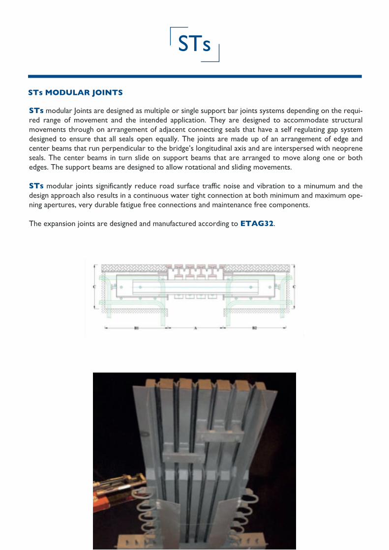
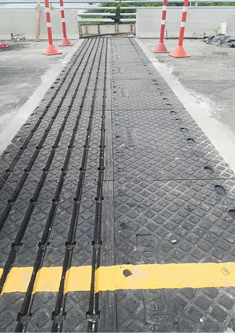
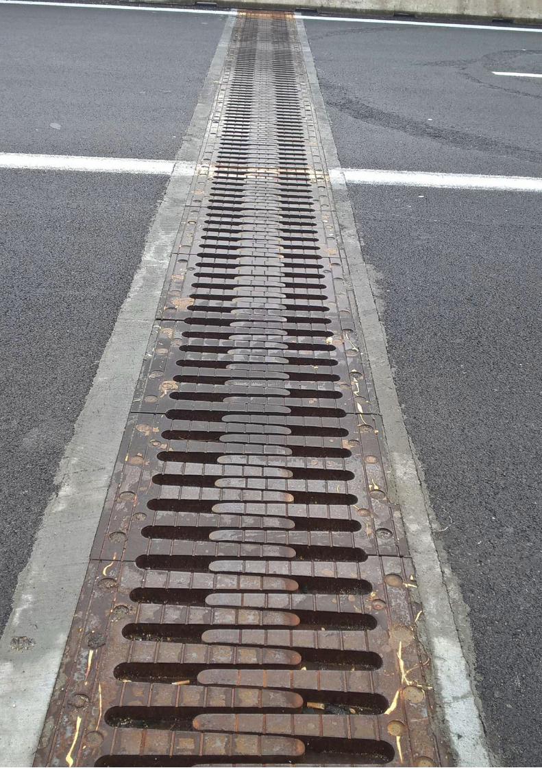
STs modular Joints are designed as multiple or single support bar joints systems depending on the requi-red range of movement and the intended application. They are designed to accommodate structural movements through on arrangement of adjacent connecting seals that have a self regulating gap system designed to ensure that all seals open equally. The joints are made up of an arrangement of edge and center beams that run perpendicular to the bridge’s longitudinal axis and are interspersed with neoprene seals. The center beams in turn slide on support beams that are arranged to move along one or both edges. The support beams are designed to allow rotational and sliding movements.
STs modular joints significantly reduce road surface traffic noise and vibration to a minumum and the design approach also results in a continuous water tight connection at both minimum and maximum ope-ning apertures, very durable fatigue free connections and maintenance free components.
The expansion joints are designed and manufactured according to ETAG32.
STs MODULAR JOINTS
STs

TYPES
TYPE MOVEMENT AMIN [mm] AMAX [mm] B1 B2 C
STs 160
STs 240
STs 320
160 150 310 200 290
240 230 470 300 290
320 310 630 380 320
400 390 790 460 320
480 470 960 540 330
560 550 1110 620 330
640 630 1270 700 330
720 710 1430 780 350
800 790 1590 860 350
880 870 1750 940 370
960 950 1910 1020 370
1040 1030 2070 1100 400
1120 1110 2230 1180 420
1200 1190 2390 1260
200
300
380
460
540
620
700
780
860
940
1020
1100
1180
1260 420
STs 400
STs 480
STs 560
STs 640
STs 720
STs 800
STs 880
STs 960
STs 1040
STs 1120
STs 1200
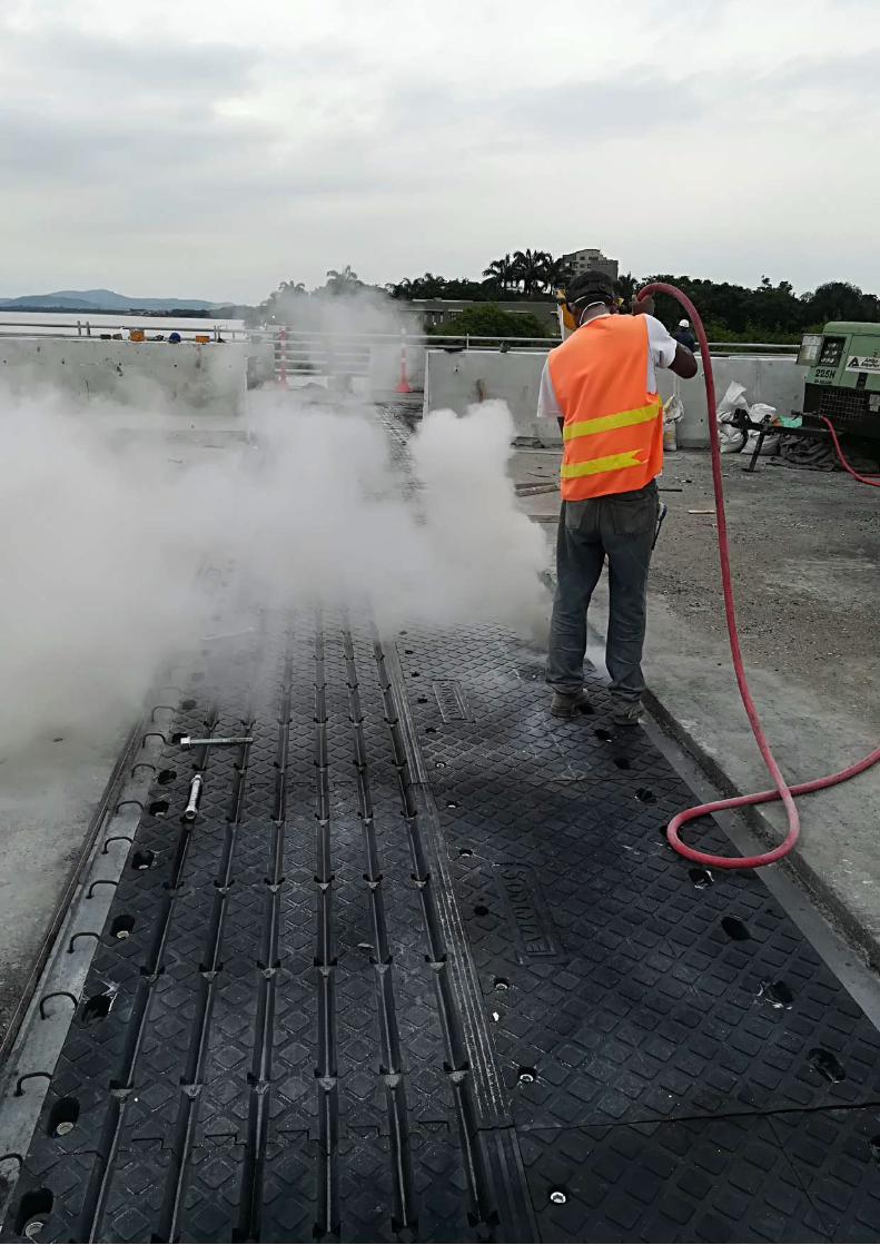

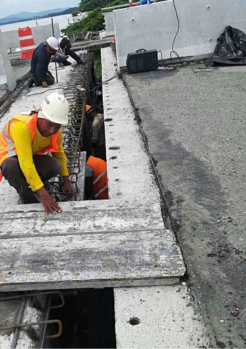
INSTALLATIONThe installation of the joint must take place after a sufficient period of settling of the road paving.The diffe-rential yielding of the asphalt due by traffic doesn’t occur near the joint, because the high strength mortars used prevent every lowering.Therefore It is advisable to install the joints after at least 6 months following the opening to traffic on final pavement.Alternatively we invite you to increase the vibro-rolling near the joint, in order to reduce the the gaps and to limit as much as possible the subsequent settling of the pavement.
PRELIMINARY PHASE
• Cut of asphalt;• Removal of the paving and bush-hammering;• Placing of the drainage system;• Preparation of the site of the joint; • of mortar or shrinkage compensating grout to create the support surface of the joint;• Tracing holes.
POSITIONING OF THE JOINT • Positioning of the panels of the joint (in the case of loads over 30 kg, use a lifting tool);• Drilling and grouting of anchors;• Tightening of the anchor nuts with torque indicated on the project;• Realization of the transition areas;• Sealing of the housing slots for the anchors until complete filling.


Legal Head Office Via Nicola Marchese, 10 - 00141 Roma Italy
TEL: +39 06 45769160FAX: +39 06 45769161
www.sommainternational.com
Via dei Colonizzatori Snc - 04011 Aprilia (LT) Italy