expanding i/o on an arduino pro micro, version 1
TRANSCRIPT

R. G. Sparber July 21, 2017 Page 1 of 39
Expanding I/O on an Arduino Pro Micro,
Version 1.0
By R. G. Sparber Protected by Creative Commons.1 Another good tutorial on i2c is http://web.engr.oregonstate.edu/~traylor/ece473/lectures/twi.pdf and includes: TWI Registers -TWBR (bit rate register) -Controls the period of SCL when the TWI module is operating in Master mode -TWAR (address register) -Used when TWI module is receiving data to identify its address. -TWCR (control register) -Controls operation of the TWI unit -Used to generate START, STOP, ACK pulse -Also enables TWI operation including interrupt enables -TWSR (status register) -Reflects the status of the TWI logic bus via codes. -Holds the prescale value for the TWI SCL pulse generator -TWDR (data register) -In transmit mode, it holds the data to send -In receive mode, it holds the data received The Arduino Pro Micro has 17 pins that can be configured to be digital Inputs or Outputs (I/O). But what if I need more? I could go to a larger Arduino or I could attach a Port Expander. This device connects to two of my I/O pins and gives me 16 more I/O pins. The cost is $3 at Adafruit.com. Adafruit also supplies the hardware specific software, called drivers, so I don't have to understand the bit level details of how this all works. Mmm, that sure was a nice dream!
1 This work is licensed under the Creative Commons Attribution 4.0 International License. To view a copy of this license, visit http://creativecommons.org/licenses/by/4.0/ or send a letter to Creative Commons, PO Box 1866, Mountain View, CA 94042, USA.

R. G. Sparber July 21, 2017 Page 2 of 39
My hard reality is it didn't work. Sure I could connect those wires and it was very easy to download the drivers to my software development environment. It was also easy to download a sample program to demonstrate how it works. But it didn't work. Over many days, I found myself digging deeper and deeper into this system trying to understand what was wrong. I have no doubt that the drivers and Port Expander all worked at one time. Something changed. I won't know what is broken until I fix it.
R. G. Sparber July 21, 2017 Page 3 of 39
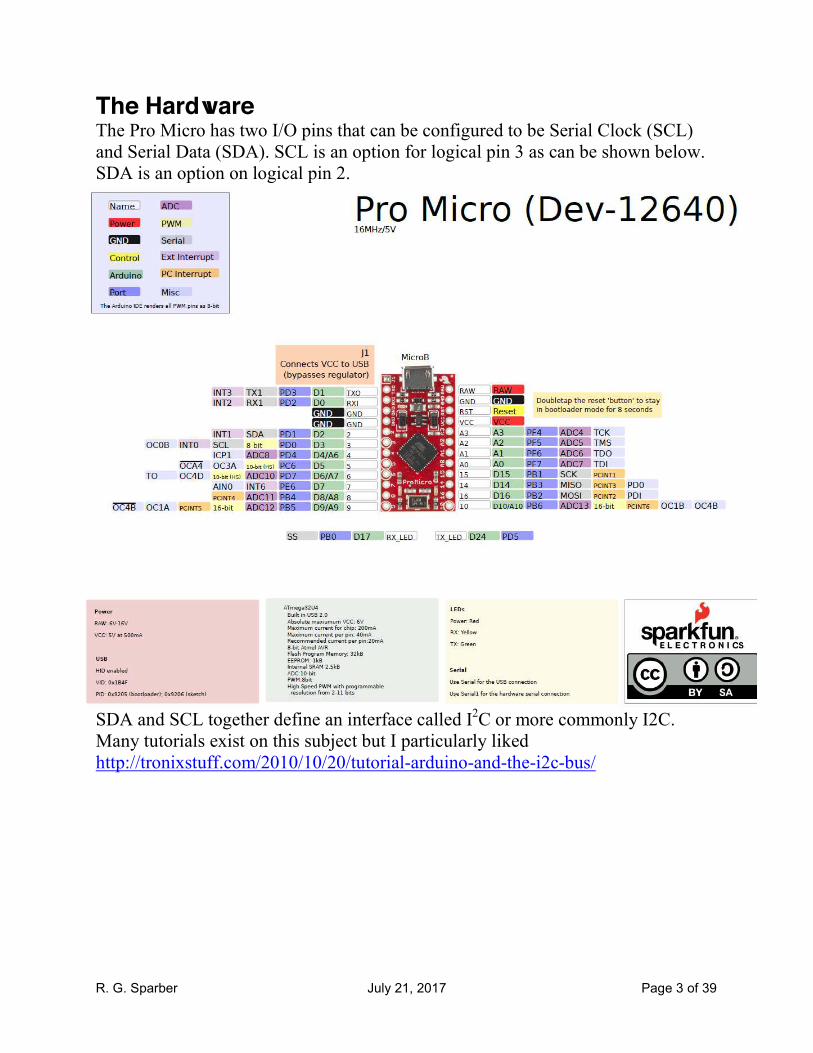
The Hardware The Pro Micro has two I/O pins that can be configured to be Serial Clock (SCL) and Serial Data (SDA). SCL is an option for logical pin 3 as can be shown below. SDA is an option on logical pin 2.
SDA and SCL together define an interface called I2C or more commonly I2C. Many tutorials exist on this subject but I particularly liked http://tronixstuff.com/2010/10/20/tutorial-arduino-and-the-i2c-bus/

R. G. Sparber July 21, 2017 Page 4 of 39
The basic idea of I2C is that with just SDA and SCL I can connect devices together and pass data. The arrangement is called
Master-Slave. The Master is in control at all times and is the Pro Micro. The Port Expander is the Slave. The Master calls on the Slave and only then does the Slave respond. Each Slave must have a unique name so there is no confusion as to who responds. This name is called an "address". My Port Expander has 3 bits for address and 16 I/O ports. This means that my 2 data pins on the Pro Micro can be expanded to 8 X 16 = 128 I/O pins. Of course this also means that a fault on either wire in the I2C bus or in any Slave can take down all 128 I/O pins. No free lunch. The Port Expander is an MCP23017. Notice physical pin 12 is SCL and physical pin 13 is SDA. Physical pins 15, 16, and 17 define its address. With all 3 of these pins tied to ground, this address is 000. This is also the default address for the drivers.

R. G. Sparber July 21, 2017 Page 5 of 39
The Pro Micro can be configured to attach 100K pull up resistors to any digital pin but that resistance is too large to insure a usable data rate. External pull up resistors are added by the user. I chose to use 1K. A 'scope on the I2C wires shows a rise time due to the parasitic capacitance plus the 1K resistor to be similar to the fall time set by the devices. The MCP23017's spec sheet can be found at http://ww1.microchip.com/downloads/en/DeviceDoc/21952b.pdf As needed, I will be taking screen shots of various parts of this document.

R. G. Sparber July 21, 2017 Page 6 of 39
The Software First, a word of caution. My background is in hardware although I have done some programming over the years. Much of what follows is from looking at the drivers and trying to make sense of them. I most likely will get some things wrong. Let me know where I went off the rails and it will be corrected. The I2C bus has its driver and the MCP23017 (I'll call it just MCP), has another set of drivers. Both reside in the Pro Micro. The MCP is just hardware and does not run any software. The I2C driver is called Wire.h and is linked to Wire.cpp. The ".h" means header and the ".cpp" means C++ which is a programming language. Together they offer a selection of commands which let a programmer control the I2C interface. The MCP driver is called Adafruit_MCP23017.h and is linked to Adafruit_MCP23017.cpp. The .h files contain mostly definitions of constants. The .cpp files hold the software. I will start at the highest level and drill down. My chosen starting point is a program that lets me connect a push button to the MCP. When pushed, it lights an LED built into the Pro Micro.
R. G. Sparber July 21, 2017 Page 7 of 39
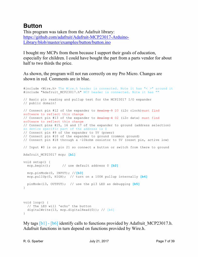
Button This program was taken from the Adafruit library: https://github.com/adafruit/Adafruit-MCP23017-Arduino-Library/blob/master/examples/button/button.ino I bought my MCPs from them because I support their goals of education, especially for children. I could have bought the part from a parts vendor for about half to two thirds the price. As shown, the program will not run correctly on my Pro Micro. Changes are shown in red. Comments are in blue. #include <Wire.h> The Wire.h header is connected. Note it has "< >" around it #include "Adafruit_MCP23017.h" MCP header is connected. Note it has "" // Basic pin reading and pullup test for the MCP23017 I/O expander // public domain! // Connect pin #12 of the expander to Analog 5 D3 (i2c clock)must find software to reflect this change // Connect pin #13 of the expander to Analog 4 D2 (i2c data) must find software to reflect this change // Connect pins #15, 16 and 17 of the expander to ground (address selection) so device specific part of the address is 0 // Connect pin #9 of the expander to 5V (power) // Connect pin #10 of the expander to ground (common ground) // Connect pin #18 through a ~10kohm resistor to 5V (reset pin, active low) // Input #0 is on pin 21 so connect a button or switch from there to ground Adafruit_MCP23017 mcp; [b1] void setup() { mcp.begin(); // use default address 0 [b2] mcp.pinMode(0, INPUT); //[b3] mcp.pullUp(0, HIGH); // turn on a 100K pullup internally [b4] pinMode(13, OUTPUT); // use the p13 LED as debugging [b5] } void loop() { // The LED will 'echo' the button digitalWrite(13, mcp.digitalRead(0)); // [b6] }
My tags [b1] - [b6] identify calls to functions provided by Adafruit_MCP23017.h. Adafruit functions in turn depend on functions provided by Wire.h.

R. G. Sparber July 21, 2017 Page 8 of 39
Adafruit_MCP23017 mcp; [b1] Here is one of the holes in my knowledge. I can guess that this command line equates "mcp" with Adafruit_MCP23017 because I see mcp prepended to each function found in Adafruit_MCP23017.cpp.
mcp.begin(); [b2] Looking in the Adafruit_MCP23017.h file, I see public: void begin(uint8_t addr); void begin(void); This says that begin( ), in its two forms, is to be publically known. Another section of the code shows Private functions. Note that there are two valid formats for begin( ). The first passes a single byte that will be called "addr". The second is with nothing being passed and that is what is used in my application. Looking in Adafruit_MCP23017.cpp I find the code for begin(uint8_t addr); Note that this is C++ so some of the commands look different from Arduino code. At line 110: /** * Initializes the MCP23017 given its HW selected address, see datasheet for Address selection. In my case it will be 0. */ void Adafruit_MCP23017::begin(uint8_t addr) { if (addr > 7) { addr = 7; The address cannot be more than 7 given that the MCP only has 3 pins to define it. The programmer has chosen to force the address to be 7 if the user specifies a value more than 7. } i2caddr = addr; A more understandable name is given to the address passed in from the user. Wire.begin(); [b2.1] Now we start down the "rabbit hole". Time to get into the Wire code. // set defaults!

R. G. Sparber July 21, 2017 Page 9 of 39
// all inputs on port A and B writeRegister(MCP23017_IODIRA,0xff); [b2.2]this is a Wire function writeRegister(MCP23017_IODIRB,0xff); [b2.3] } This writes all ones to both the IODIR A and B registers. The spec sheet, section 1.6.1 says that this will set all ports to inputs.
At line 130 I find the definition of begin( ) when nothing is passed: /** * Initializes the default MCP23017, with 000 for the configurable part of the address */ void Adafruit_MCP23017::begin(void) { begin(0); This says that if the program sees begin(); call begin(0); which then executes the code starting at line 110. }

R. G. Sparber July 21, 2017 Page 10 of 39
Wire.begin(); [b2.1] Summary: transmit and receive buffer length and index are initialized; low level hardware functions are performed that turn on internal pull up resistors and set the bus data rate. These pull up resistors are supplemented by resistors added by the user. In Wire.h, starting at line 50: public: TwoWire(); void begin(); void begin(uint8_t); void begin(int); So this is saying that begin(); is public and the user can call it.

R. G. Sparber July 21, 2017 Page 11 of 39
In Wire.cpp, starting at line 52: // Public Methods ////////////////////////////////////////////////////////////// void TwoWire::begin(void) The original author of this file called it TwoWire but it was renamed Wire. It is not clear to me how using the original name here works. { rxBufferIndex = 0; When begin() is invoked, receive and transmit parameters are set rxBufferLength = 0; txBufferIndex = 0; txBufferLength = 0; twi_init(); [b2.1.1] } void TwoWire::begin(uint8_t address) Although not called yet, I have included the two remaining forms of begin. This one passes the byte called "address". { twi_setAddress(address); twi_attachSlaveTxEvent(onRequestService); twi_attachSlaveRxEvent(onReceiveService); begin(); } void TwoWire::begin(int address) This version of begin passes an integer called address and simply converts the integer to a byte. { begin((uint8_t)address); }

R. G. Sparber July 21, 2017 Page 12 of 39
twi_init();[b2.1.1] Supporting Information From ATmega32U4 spec sheet: PRTWI powers up to 0 so turns on the TWI. If turned off via sleep, this bit must be written back to 0. • INT1/SDA – Port D, Bit 1 SDA, 2-wire Serial Interface Data: When the TWEN bit in TWCR is set (one) to enable the 2-wire Serial Interface, pin PD1 is disconnected from the port and becomes the Serial Data I/O pin for the 2-wire Serial Interface. In this mode, there is a spike filter on the pin to suppress spikes shorter than 50ns on the input signal, and the pin is driven by an open drain driver with slew-rate limitation. • INT0/SCL/OC0B – Port D, Bit 0 SCL, 2-wire Serial Interface Clock: When the TWEN bit in TWCR is set (one) to enable the 2-wire Serial Interface, pin PD0 is disconnected from the port and becomes the Serial Clock I/O pin for the 2-wire Serial Interface. In this mode, there is a spike filter on the pin to suppress spikes shorter than 50ns on the input signal, and the pin is driven by an open drain driver with slew-rate limitation. 20.5.1 SCL and SDA Pins These pins interface the AVR TWI with the rest of the MCU system. The output drivers contain a slew-rate limiter in order to conform to the TWI specification. The input stages contain a spike suppression unit removing spikes shorter than 50ns. Note that the internal pull-ups in the AVR pads can be enabled by setting the PORT bits corresponding to the SCL and SDA pins, as explained in the I/O Port section. The internal pull-ups can in some systems eliminate the need for external ones.
the command cbi(TWSR, TWPS1) will ensure that the value of the TWPS1 (1st) bit of
the TWSR is 0. sbi(TWSR, TWPS1) also exists which seems to set TWSR to 1

R. G. Sparber July 21, 2017 Page 13 of 39
Summary: twi_init(void) is doing low level hardware operations that provide pull up resistors and change the data rate. /* * Function twi_init * Desc readys twi pins and sets twi bitrate * Input none * Output none */ void twi_init(void) { // initialize state twi_state = TWI_READY; //defined in twi.h #define TWI_READY 0 twi_sendStop = true; // default value twi_inRepStart = false; // activate internal pullups for twi. digitalWrite(SDA, 1); //I am not seeing the pullups active on this pin and don't see SDA as a key word in the mega spec sheet. I do see PUOExn which is Pull Up Override Enable for pin xn (xn = D0 for SCL and D1 for SDA I think). This enables the mux and I must then write PUOVxn which is Pull Up Override Value for pin xn). A 1 turns it on. WHICH REGISTER IS THIS? digitalWrite(SCL, 1); //SINCE CLOCK IS AN OUTPUT, WHY TRY TO ENABLE PULL UP? // initialize twi prescaler and bit rate cbi(TWSR, TWPS0); //clear the TWPS0 bit in register TWSR cbi(TWSR, TWPS1); //clear the TWPS1 bit in register TWSR TWBR = ((F_CPU / TWI_FREQ) - 16) / 2; //calculates the I2C rate and puts it into register TWBR (Two Wire Bit Rate?) /* twi bit rate formula from atmega128 manual pg 204 SCL Frequency = CPU Clock Frequency / (16 + (2 * TWBR)) note: TWBR should be 10 or higher for master mode It is 72 for a 16mhz Wiring board with 100kHz TWI */ // enable twi module, acks, and twi interrupt TWCR = _BV(TWEN) | _BV(TWIE) | _BV(TWEA); }

R. G. Sparber July 21, 2017 Page 14 of 39
A search of the web turned up twi.c at https://android.googlesource.com/platform/external/arduino/+/jb-mr1-dev/libraries/Wire/utility/twi.c
void
twi_init(void)
{
// initialize state
twi_state = TWI_READY;
#if defined(__AVR_ATmega168__) || defined(__AVR_ATmega8__) || defined(__AVR_ATmega328P__)
// activate internal pull-ups for twi Ah, so it is turning on I2C pull ups inside of the Arduino except that I don't see it by measuring the pins
// as per note from atmega8 manual pg167
sbi(PORTC, 4); it looks like sbi means single bit instruction and lets the user change one bit without changing the
remaining bits in the byte
sbi(PORTC, 5);
#else
// activate internal pull-ups for twi
// as per note from atmega128 manual pg204
sbi(PORTD, 0);
sbi(PORTD, 1);
#endif
// initialize twi prescaler and bit rate It is also looks like it is playing with the data rate on the I2C bus
cbi(TWSR, TWPS0);
cbi(TWSR, TWPS1);
TWBR = ((CPU_FREQ / TWI_FREQ) - 16) / 2;
/* twi bit rate formula from atmega128 manual pg 204
R. G. Sparber July 21, 2017 Page 15 of 39
SCL Frequency = CPU Clock Frequency / (16 + (2 * TWBR))
note: TWBR should be 10 or higher for master mode
It is 72 for a 16mhz Wiring board with 100kHz TWI */
// enable twi module, acks, and twi interrupt
TWCR = _BV(TWEN) | _BV(TWIE) | _BV(TWEA); //is a stop condition that goes directly to hardware
}
R. G. Sparber July 21, 2017 Page 16 of 39
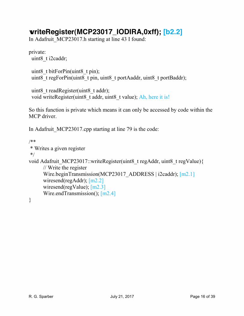
writeRegister(MCP23017_IODIRA,0xff); [b2.2] In Adafruit_MCP23017.h starting at line 43 I found: private: uint8_t i2caddr; uint8_t bitForPin(uint8_t pin); uint8_t regForPin(uint8_t pin, uint8_t portAaddr, uint8_t portBaddr); uint8_t readRegister(uint8_t addr); void writeRegister(uint8_t addr, uint8_t value); Ah, here it is! So this function is private which means it can only be accessed by code within the MCP driver. In Adafruit_MCP23017.cpp starting at line 79 is the code: /** * Writes a given register */ void Adafruit_MCP23017::writeRegister(uint8_t regAddr, uint8_t regValue){ // Write the register Wire.beginTransmission(MCP23017_ADDRESS | i2caddr); [m2.1] wiresend(regAddr); [m2.2] wiresend(regValue); [m2.3] Wire.endTransmission(); [m2.4] }
R. G. Sparber July 21, 2017 Page 17 of 39
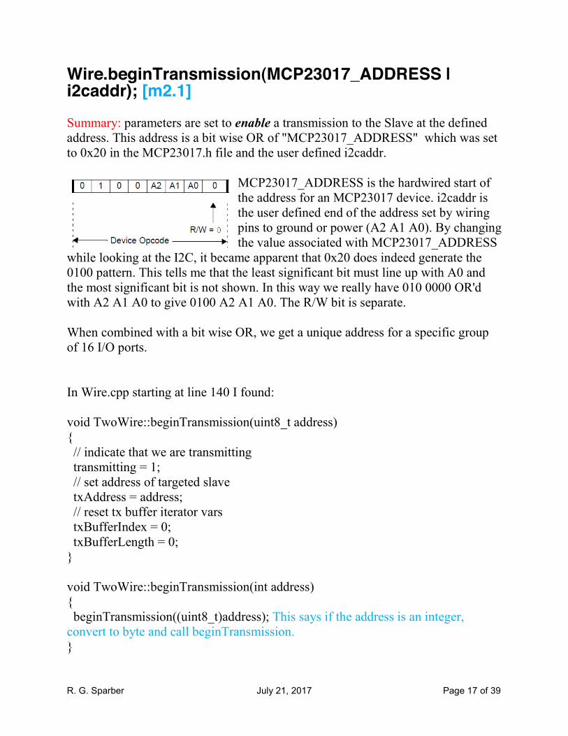
Wire.beginTransmission(MCP23017_ADDRESS | i2caddr); [m2.1] Summary: parameters are set to enable a transmission to the Slave at the defined address. This address is a bit wise OR of "MCP23017_ADDRESS" which was set to 0x20 in the MCP23017.h file and the user defined i2caddr.
MCP23017_ADDRESS is the hardwired start of the address for an MCP23017 device. i2caddr is the user defined end of the address set by wiring pins to ground or power (A2 A1 A0). By changing the value associated with MCP23017_ADDRESS
while looking at the I2C, it became apparent that 0x20 does indeed generate the 0100 pattern. This tells me that the least significant bit must line up with A0 and the most significant bit is not shown. In this way we really have 010 0000 OR'd with A2 A1 A0 to give 0100 A2 A1 A0. The R/W bit is separate. When combined with a bit wise OR, we get a unique address for a specific group of 16 I/O ports. In Wire.cpp starting at line 140 I found: void TwoWire::beginTransmission(uint8_t address) { // indicate that we are transmitting transmitting = 1; // set address of targeted slave txAddress = address; // reset tx buffer iterator vars txBufferIndex = 0; txBufferLength = 0; } void TwoWire::beginTransmission(int address) { beginTransmission((uint8_t)address); This says if the address is an integer, convert to byte and call beginTransmission. }
R. G. Sparber July 21, 2017 Page 18 of 39
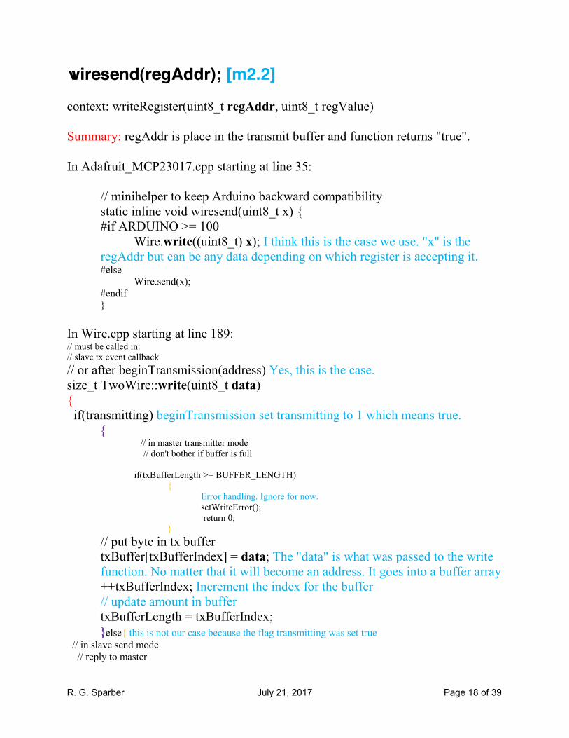
wiresend(regAddr); [m2.2] context: writeRegister(uint8_t regAddr, uint8_t regValue) Summary: regAddr is place in the transmit buffer and function returns "true". In Adafruit_MCP23017.cpp starting at line 35:
// minihelper to keep Arduino backward compatibility static inline void wiresend(uint8_t x) { #if ARDUINO >= 100 Wire.write((uint8_t) x); I think this is the case we use. "x" is the regAddr but can be any data depending on which register is accepting it. #else Wire.send(x); #endif }
In Wire.cpp starting at line 189: // must be called in: // slave tx event callback
// or after beginTransmission(address) Yes, this is the case. size_t TwoWire::write(uint8_t data) { if(transmitting) beginTransmission set transmitting to 1 which means true.
{ // in master transmitter mode // don't bother if buffer is full
if(txBufferLength >= BUFFER_LENGTH)
{ Error handling. Ignore for now.
setWriteError(); return 0;
}
// put byte in tx buffer txBuffer[txBufferIndex] = data; The "data" is what was passed to the write function. No matter that it will become an address. It goes into a buffer array
++txBufferIndex; Increment the index for the buffer // update amount in buffer txBufferLength = txBufferIndex;
}else{ this is not our case because the flag transmitting was set true
// in slave send mode // reply to master

R. G. Sparber July 21, 2017 Page 19 of 39
twi_transmit(&data, 1); } return 1; }function returns a value of true since it did not return with error
wiresend(regValue); [m2.3] Context: writeRegister(uint8_t regAddr, uint8_t regValue) Summary: This is the same function as used for [m2.2] but this time regValue is placed in transmit buffer. The transmit buffer then has regAddr followed by regValue.
R. G. Sparber July 21, 2017 Page 20 of 39
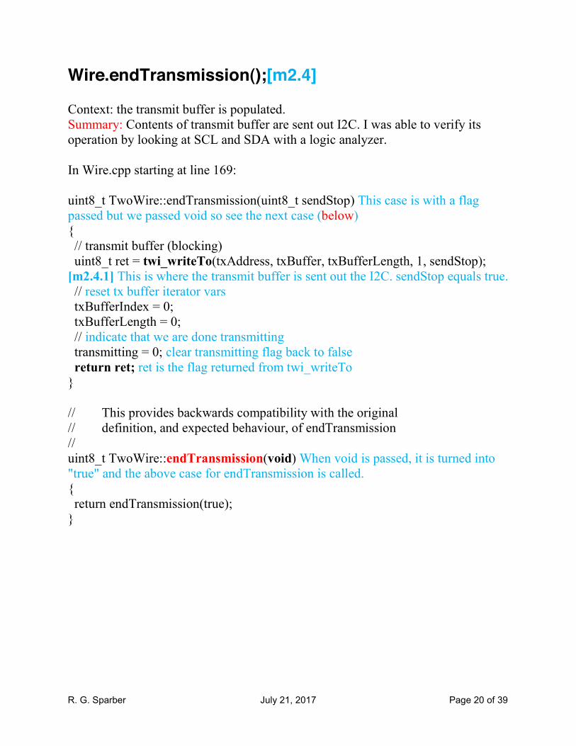
Wire.endTransmission();[m2.4] Context: the transmit buffer is populated. Summary: Contents of transmit buffer are sent out I2C. I was able to verify its operation by looking at SCL and SDA with a logic analyzer. In Wire.cpp starting at line 169: uint8_t TwoWire::endTransmission(uint8_t sendStop) This case is with a flag passed but we passed void so see the next case (below) { // transmit buffer (blocking) uint8_t ret = twi_writeTo(txAddress, txBuffer, txBufferLength, 1, sendStop); [m2.4.1] This is where the transmit buffer is sent out the I2C. sendStop equals true. // reset tx buffer iterator vars txBufferIndex = 0; txBufferLength = 0; // indicate that we are done transmitting transmitting = 0; clear transmitting flag back to false return ret; ret is the flag returned from twi_writeTo } // This provides backwards compatibility with the original // definition, and expected behaviour, of endTransmission // uint8_t TwoWire::endTransmission(void) When void is passed, it is turned into "true" and the above case for endTransmission is called. { return endTransmission(true); }

R. G. Sparber July 21, 2017 Page 21 of 39
twi_writeTo(txAddress, txBuffer, txBufferLength, 1, sendStop); [m2.4.1] Conclusion: logic analyzer says the function works. See https://android.googlesource.com/platform/external/arduino/+/jb-mr1-dev/libraries/Wire/utility/twi.c line 163 for this function. It is interfacing with the hardware directly in order to send out the bits. Rather than dig into this code, let's go back to the MCP data sheet and then look at a logic analyzer trace.
The I2C bus starts with SCL and SDA high. Then the SDA lead drop low followed by the SCL lead going low. This is the Start Condition, S.

R. G. Sparber July 21, 2017 Page 22 of 39
Next is the Device opcode (OP).
It consists of a fixed pattern of bits 0100 followed by the hard wired address of the MCP being addressed A2 A1 A0: 000. Then comes the R/W bit. If 1, it means read. If 0 it means write.

R. G. Sparber July 21, 2017 Page 23 of 39
Going back to button.ino of page 7, we can see the software executing the line
mcp.digitalRead(0); At the bottom of figure 1-1 are the read sequences.
For now, ignore where it is reading and just consider that a read is being done.
Here is a display of SCL and SDA:
Start 01000001 stoP We see the fixed pattern of 0100 followed by the device address of 000 followed by R/W of 1 so read. These bits are bracketed by the Start and Stop sequence. This
bit sequence matches the diagram shown here.
The clock should be 100 KHz or 400 KHz but the picture shows 1 MHz. This might be the root of the problem.

R. G. Sparber July 21, 2017 Page 24 of 39
Although this is a valid sequence of bits, the read should cause the MCP to respond with a value.
mcp.digitalRead(0); should be reading the state of I/O logical pin 0 also known as GPA0 which is physical pin 21 (see page 4). The lack of Dout says the MCP was not correctly configured.
Furthermore, after the R/W bit, we do not see the ACK from the MCP. This may be why the Arduino doesn't send the Register Address.

R. G. Sparber July 21, 2017 Page 25 of 39
mcp.pinMode(0, INPUT); [b3] Summary: The "0" is the logical port number and "INPUT" is how it will be configured. This mimics the Arduino function pinMode(0,INPUT); It is understood that we are setting up an MCP23017. In MCP23017.h are all register addresses. We also know that pin names less than 8 are in the A register while those greater than 8 and less than 16 are in the B register. Adafruit_MCP23017.cpp line 134 defines it: /** * Sets the pin mode to either INPUT or OUTPUT */ void Adafruit_MCP23017::pinMode(uint8_t p, uint8_t d) { p is the port number and d is the configuration called INPUT updateRegisterBit(p,(d==INPUT),MCP23017_IODIRA,MCP23017_IODIRB); MCP23017_IODIRA and B are defined in MCP23017.h. I think (d==INPUT) is evaluated to 1 if true and to 0 if false. So if user enters INPUX it would be treated the same as OUTPUT. } /** Since there is only one function here, let's just look at it now.

R. G. Sparber July 21, 2017 Page 26 of 39
updateRegisterBit(p,(d==INPUT),MCP23017_IODIRA,MCP23017_IODIRB) is found in Adafruit_MCP23017.cpp line 96: /** * Helper to update a single bit of an A/B register. * - Reads the current register value * - Writes the new register value */ void Adafruit_MCP23017::updateRegisterBit(uint8_t pin, uint8_t pValue, uint8_t portAaddr, uint8_t portBaddr)
{ My guess is that (d==INPUT) evalutates to 1 and becomes a byte since it is defined here is uint8_t pValue. uint8_t regValue; define regValue as a byte uint8_t regAddr=regForPin(pin,portAaddr,portBaddr); [b3.1] The pin value is used to return which port address to use. uint8_t bit=bitForPin(pin); [b3.2] returns 0 if pin is less than 8. It returns 1 if pin is 8<pin<16 regValue = readRegister(regAddr); [b3.3] // set the value for the particular bit
bitWrite(regValue,bit,pValue); [b3.4] I think this is where the conversion from logical to byte means that if the
user enters INPUT they get a 1 written here. A 1 means INPUT. writeRegister(regAddr,regValue); [b3.5]
}
R. G. Sparber July 21, 2017 Page 27 of 39
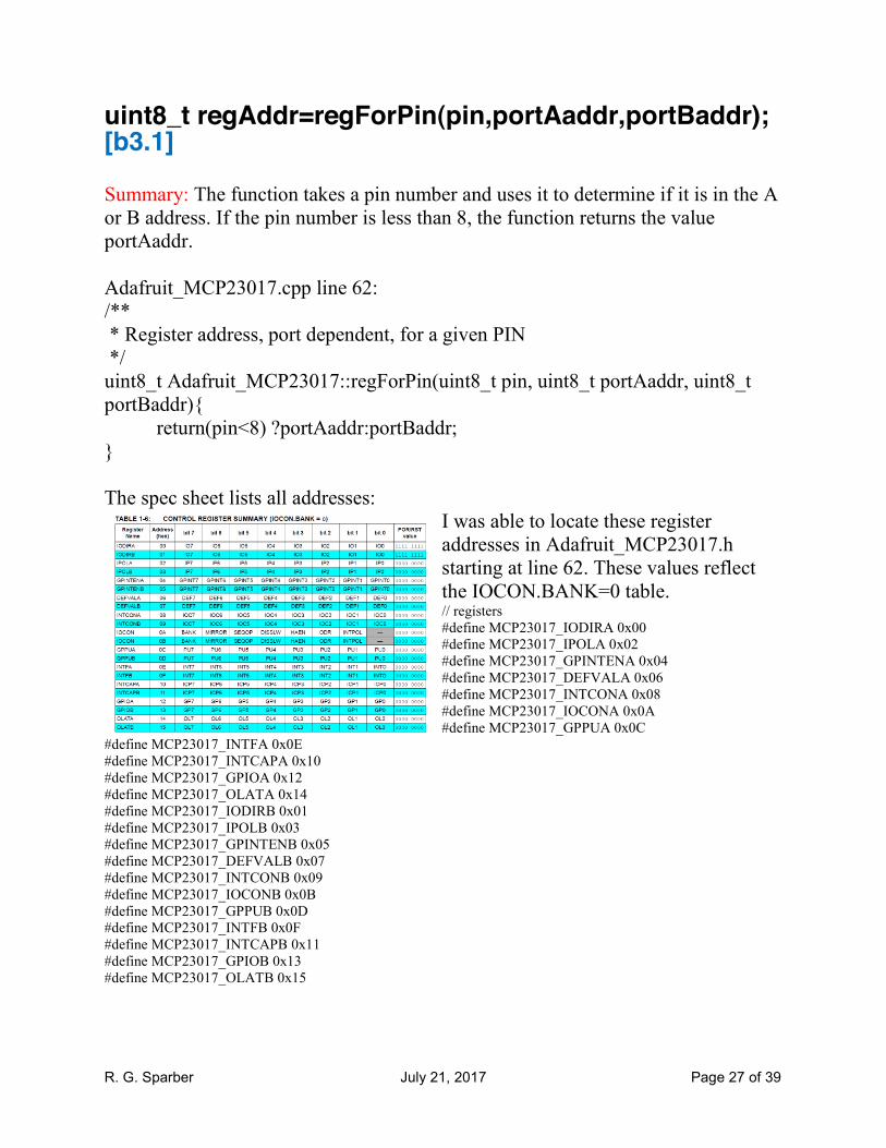
uint8_t regAddr=regForPin(pin,portAaddr,portBaddr); [b3.1] Summary: The function takes a pin number and uses it to determine if it is in the A or B address. If the pin number is less than 8, the function returns the value portAaddr. Adafruit_MCP23017.cpp line 62: /** * Register address, port dependent, for a given PIN */ uint8_t Adafruit_MCP23017::regForPin(uint8_t pin, uint8_t portAaddr, uint8_t portBaddr){ return(pin<8) ?portAaddr:portBaddr; } The spec sheet lists all addresses:
I was able to locate these register addresses in Adafruit_MCP23017.h starting at line 62. These values reflect the IOCON.BANK=0 table. // registers #define MCP23017_IODIRA 0x00 #define MCP23017_IPOLA 0x02 #define MCP23017_GPINTENA 0x04 #define MCP23017_DEFVALA 0x06 #define MCP23017_INTCONA 0x08 #define MCP23017_IOCONA 0x0A #define MCP23017_GPPUA 0x0C
#define MCP23017_INTFA 0x0E #define MCP23017_INTCAPA 0x10 #define MCP23017_GPIOA 0x12 #define MCP23017_OLATA 0x14 #define MCP23017_IODIRB 0x01 #define MCP23017_IPOLB 0x03 #define MCP23017_GPINTENB 0x05 #define MCP23017_DEFVALB 0x07 #define MCP23017_INTCONB 0x09 #define MCP23017_IOCONB 0x0B #define MCP23017_GPPUB 0x0D #define MCP23017_INTFB 0x0F #define MCP23017_INTCAPB 0x11 #define MCP23017_GPIOB 0x13 #define MCP23017_OLATB 0x15
R. G. Sparber July 21, 2017 Page 28 of 39
uint8_t bit=bitForPin(pin); [b3.2] Summary: The function returns 0 if pin is less than 8. It returns 1 if pin is 8<pin<16. From the C++ standard: "the binary % operator yields the remainder from the division of the first expression by the second. If the second operand of / or % is zero the behavior is undefined; otherwise (a/b)*b + a%b is equal to a. If both operands are nonnegative then the remainder is nonnegative; if not, the sign of the remainder is implementation-defined". Furthermore, they always round down. So pin%8 means divide pin by 8. If pin is <8, the result is 0. If 8<pin<16 the result is 1. /** * Bit number associated to a give Pin */ uint8_t Adafruit_MCP23017::bitForPin(uint8_t pin){ return pin%8; } /**

R. G. Sparber July 21, 2017 Page 29 of 39
regValue = readRegister(regAddr); [b3.3] Summary: Function returns the contents of regAddr for the previously selected MCP23017. /** * Reads a given register */ uint8_t Adafruit_MCP23017::readRegister(uint8_t addr){ // read the current GPINTEN Wire.beginTransmission(MCP23017_ADDRESS | i2caddr); parameters are set to enable a transmission to the Slave at the defined address. This address is a bit wise OR of "MCP23017_ADDRESS" which was set to 0x20 in the MCP23017.h file and the user defined i2caddr. .h line 60 defines MCP23017_ADDRESS as 0x20 and i2caddr was passed when the user called begin() COULD BE CHANGED LATER; See [b2]. The default value is 0. These two values are bit OR'd: 0x20 is b0100 0000. See [m2.1] for beginTransmission() wiresend(addr); addr is place in the transmit buffer and function returns "true" Wire.endTransmission(); Contents of transmit buffer are sent out I2C. Wire.requestFrom(MCP23017_ADDRESS | i2caddr, 1); [b3.3.1] return wirerecv(); [b3.3.2] }
R. G. Sparber July 21, 2017 Page 30 of 39
Wire.requestFrom(MCP23017_ADDRESS | i2caddr, 1); [b3.3.1] Summary: Found a possible bug with rxBuffer not defined but it looks like this code retrieves the contents of the specified address inside the MCP23017. A series of same named functions that expect different numbers of parameters build up a set of values. These functions return a byte. All code is from wire.cpp. First step in the chain: uint8_t TwoWire::requestFrom(uint8_t address, uint8_t quantity) { address is the bit OR'd value and quantity is "1" return requestFrom((uint8_t)address, (uint8_t)quantity, (uint8_t)true); } true is added Second step in the chain: uint8_t TwoWire::requestFrom(uint8_t address, uint8_t quantity, uint8_t sendStop) { sendStop is true return requestFrom((uint8_t)address, (uint8_t)quantity, (uint32_t)0, (uint8_t)0, (uint8_t)sendStop); This function adds 0, 0 }
R. G. Sparber July 21, 2017 Page 31 of 39
Third step in the chain: uint8_t TwoWire::requestFrom(uint8_t address, uint8_t quantity, uint32_t iaddress, uint8_t isize, uint8_t sendStop) { iaddress is 0, isize is 0 if (isize > 0)
{ in this case isize is 0 // send internal address; this mode allows sending a repeated start to access // some devices' internal registers. This function is executed by the hardware
NO GUARANTEE THAT MY HARDWARE DOES THIS // TWI module on other processors (for example Due's TWI_IADR and TWI_MMR registers)
beginTransmission(address); address is MCP23017_ADDRESS | i2caddr // the maximum size of internal address is 3 bytes if (isize > 3)
{ isize is 0 so is false
isize = 3; } // write internal register address - most significant byte first while (isize-- > 0) first decrement isize by 1 and see if > 0 so is false write((uint8_t)(iaddress >> (isize*8))); endTransmission(false); }
// clamp to buffer length if(quantity > BUFFER_LENGTH)
{ quantity is 1 and in Wire.h BUFFER_LENGTH was defined as 32 so this is false quantity = BUFFER_LENGTH; } // perform blocking read into buffer uint8_t read = twi_readFrom(address, rxBuffer, quantity, sendStop); [b3.1.1.1] address was defined by user, rxBuffer is UNDEFINED , quantity is 1, sendStop is true // set rx buffer iterator vars rxBufferIndex = 0; rxBufferLength = read; return read; }
R. G. Sparber July 21, 2017 Page 32 of 39
twi_readFrom(address, rxBuffer, quantity, sendStop); [b3.1.1.1] This must be sourced from #include "utility/twi.h"
R. G. Sparber July 21, 2017 Page 33 of 39
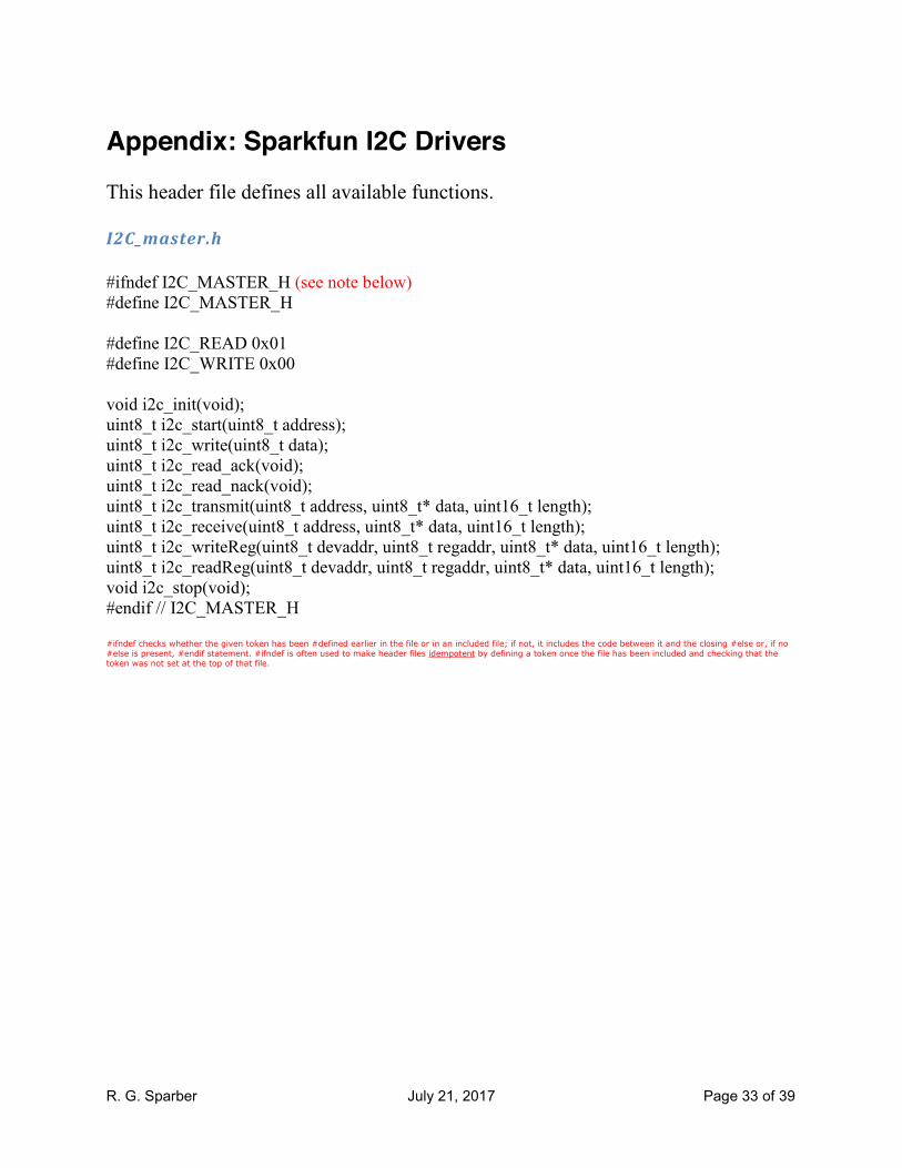
Appendix: Sparkfun I2C Drivers This header file defines all available functions. I2C_master.h
#ifndef I2C_MASTER_H (see note below) #define I2C_MASTER_H #define I2C_READ 0x01 #define I2C_WRITE 0x00 void i2c_init(void); uint8_t i2c_start(uint8_t address); uint8_t i2c_write(uint8_t data); uint8_t i2c_read_ack(void); uint8_t i2c_read_nack(void); uint8_t i2c_transmit(uint8_t address, uint8_t* data, uint16_t length); uint8_t i2c_receive(uint8_t address, uint8_t* data, uint16_t length); uint8_t i2c_writeReg(uint8_t devaddr, uint8_t regaddr, uint8_t* data, uint16_t length); uint8_t i2c_readReg(uint8_t devaddr, uint8_t regaddr, uint8_t* data, uint16_t length); void i2c_stop(void); #endif // I2C_MASTER_H #ifndef checks whether the given token has been #defined earlier in the file or in an included file; if not, it includes the code between it and the closing #else or, if no
#else is present, #endif statement. #ifndef is often used to make header files idempotent by defining a token once the file has been included and checking that the token was not set at the top of that file.

R. G. Sparber July 21, 2017 Page 34 of 39
This .c file contains the logic
I2C_master.c #ifndef F_CPU //if F_CPU has not been defined yet, define it as this value #define F_CPU 16000000UL #endif #include <avr/io.h> //I think this is the software related to the processor #include <util/twi.h> //this is the same bit level driver set used by Wire #include "i2c_master.h" #define F_SCL 100000UL // SCL frequency #define Prescaler 1 #define TWBR_val ((((F_CPU / F_SCL) / Prescaler) - 16 ) / 2) //calculates a value related to the I2C rate void i2c_init(void) //sets bit rate of i2c { TWBR = (uint8_t)TWBR_val; // TWBR (bit rate register) }

R. G. Sparber July 21, 2017 Page 35 of 39
uint8_t i2c_start(uint8_t address) { // reset TWI control register TWCR = 0; // transmit START condition TWCR = (1<<TWINT) | (1<<TWSTA) | (1<<TWEN); // wait for end of transmission while( !(TWCR & (1<<TWINT)) ); // check if the start condition was successfully transmitted if((TWSR & 0xF8) != TW_START){ return 1; } // load slave address into data register TWDR = address; // start transmission of address TWCR = (1<<TWINT) | (1<<TWEN); // wait for end of transmission while( !(TWCR & (1<<TWINT)) ); // check if the device has acknowledged the READ / WRITE mode uint8_t twst = TW_STATUS & 0xF8; if ( (twst != TW_MT_SLA_ACK) && (twst != TW_MR_SLA_ACK) ) return 1; return 0; //it is not clear if a return of 1 means got ACK } uint8_t i2c_write(uint8_t data) //writing a register in a device tied to the I2C [could this data be the register address?] { // load data into data register TWDR = data; // start transmission of data TWCR = (1<<TWINT) | (1<<TWEN); // wait for end of transmission while( !(TWCR & (1<<TWINT)) ); if( (TWSR & 0xF8) != TW_MT_DATA_ACK ){ return 1; } return 0; } uint8_t i2c_read_ack(void) //read a register in a device tied to the I2C; address must have been previously defined { // start TWI module and acknowledge data after reception TWCR = (1<<TWINT) | (1<<TWEN) | (1<<TWEA); // wait for end of transmission while( !(TWCR & (1<<TWINT)) ); // return received data from TWDR return TWDR; //see spec sheet for unique meaning of TWDR. It is a hardware register name }
R. G. Sparber July 21, 2017 Page 36 of 39
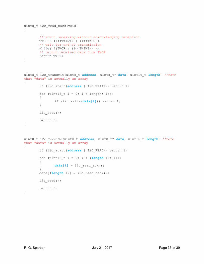
uint8_t i2c_read_nack(void) { // start receiving without acknowledging reception TWCR = (1<<TWINT) | (1<<TWEN); // wait for end of transmission while( !(TWCR & (1<<TWINT)) ); // return received data from TWDR return TWDR; } uint8_t i2c_transmit(uint8_t address, uint8_t* data, uint16_t length) //note that "data" is actually an array { if (i2c_start(address | I2C_WRITE)) return 1; for (uint16_t i = 0; i < length; i++) { if (i2c_write(data[i])) return 1; } i2c_stop(); return 0; } uint8_t i2c_receive(uint8_t address, uint8_t* data, uint16_t length) //note that "data" is actually an array { if (i2c_start(address | I2C_READ)) return 1; for (uint16_t i = 0; i < (length-1); i++) { data[i] = i2c_read_ack(); } data[(length-1)] = i2c_read_nack(); i2c_stop(); return 0; }

R. G. Sparber July 21, 2017 Page 37 of 39
uint8_t i2c_writeReg(uint8_t devaddr, uint8_t regaddr, uint8_t* data, uint16_t length) { if (i2c_start(devaddr | 0x00)) return 1; //seems to say if start fails, return 1 i2c_write(regaddr); //write register address for (uint16_t i = 0; i < length; i++)//write onto the I2C bytes contained in the data array starting at 0 and going until length is reached { if (i2c_write(data[i])) return 1; //seems to say if write of any entry in the data array returns true, function returns 1 } i2c_stop(); //I think this is just adding the stop symbol return 0; //if no failures, return 0 } uint8_t i2c_readReg(uint8_t devaddr, uint8_t regaddr, uint8_t* data, uint16_t length) { if (i2c_start(devaddr)) return 1; i2c_write(regaddr); if (i2c_start(devaddr | 0x01)) return 1; for (uint16_t i = 0; i < (length-1); i++) { data[i] = i2c_read_ack(); } data[(length-1)] = i2c_read_nack(); i2c_stop(); return 0; } void i2c_stop(void) //certainly odd that this function has no inputs or outputs. This implies that the variable TWCR talks directly to hardware { // transmit STOP condition TWCR = (1<<TWINT) | (1<<TWEN) | (1<<TWSTO); }
R. G. Sparber July 21, 2017 Page 38 of 39
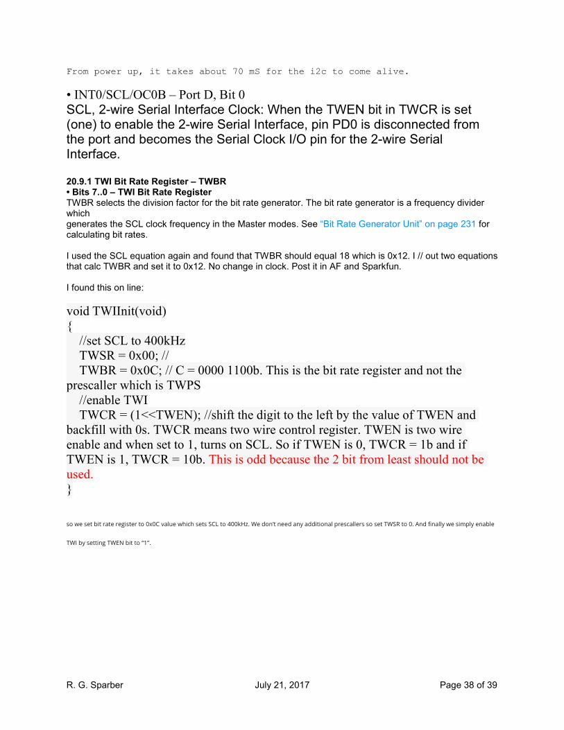
From power up, it takes about 70 mS for the i2c to come alive.
• INT0/SCL/OC0B – Port D, Bit 0 SCL, 2-wire Serial Interface Clock: When the TWEN bit in TWCR is set (one) to enable the 2-wire Serial Interface, pin PD0 is disconnected from the port and becomes the Serial Clock I/O pin for the 2-wire Serial Interface. 20.9.1 TWI Bit Rate Register – TWBR • Bits 7..0 – TWI Bit Rate Register TWBR selects the division factor for the bit rate generator. The bit rate generator is a frequency divider which generates the SCL clock frequency in the Master modes. See “Bit Rate Generator Unit” on page 231 for calculating bit rates. I used the SCL equation again and found that TWBR should equal 18 which is 0x12. I // out two equations that calc TWBR and set it to 0x12. No change in clock. Post it in AF and Sparkfun. I found this on line:
void TWIInit(void) { //set SCL to 400kHz TWSR = 0x00; // TWBR = 0x0C; // C = 0000 1100b. This is the bit rate register and not the prescaller which is TWPS //enable TWI TWCR = (1<<TWEN); //shift the digit to the left by the value of TWEN and backfill with 0s. TWCR means two wire control register. TWEN is two wire enable and when set to 1, turns on SCL. So if TWEN is 0, TWCR = 1b and if TWEN is 1, TWCR = 10b. This is odd because the 2 bit from least should not be used. }
so we set bit rate register to 0x0C value which sets SCL to 400kHz. We don’t need any additional prescallers so set TWSR to 0. And finally we simply enable
TWI by setting TWEN bit to “1”.

R. G. Sparber July 21, 2017 Page 39 of 39
I have to assume that someone has tested the I2C on this device and also for the Pro Micro. The measured SCL is 1 MHz but should be 100 KHz. Recheck the code related to setting this clock. I found an existence proof that ATmega328 i2c works. It is used on the Uno ($24) and ProMini328 ($10). I bought 3 ProMini328s on 7/18/2017 and it can take 3-10 days from tomorrow. The next challenge is to change the bootloader to accept this device. I just posted to ATMEL's formum 7/21/2017.