expander gsm 5.1 eng - acdcshop gsm 5.1 ® user guide megaelektronik.pl page 7 expander gsm 5.1 ®...
TRANSCRIPT

EXPANDER GSM 5.1 ® User Guide megaelektronik.pl Page 1
EXPANDER GSM 5.1 ® GSM Communication module Alarm control panel function GSM Remote control GSM Rap Temporal driver Thermostat GSM Build in buffer power supply
EXPANDER GSM 5.1 ® User Guide megaelektronik.pl Page 2
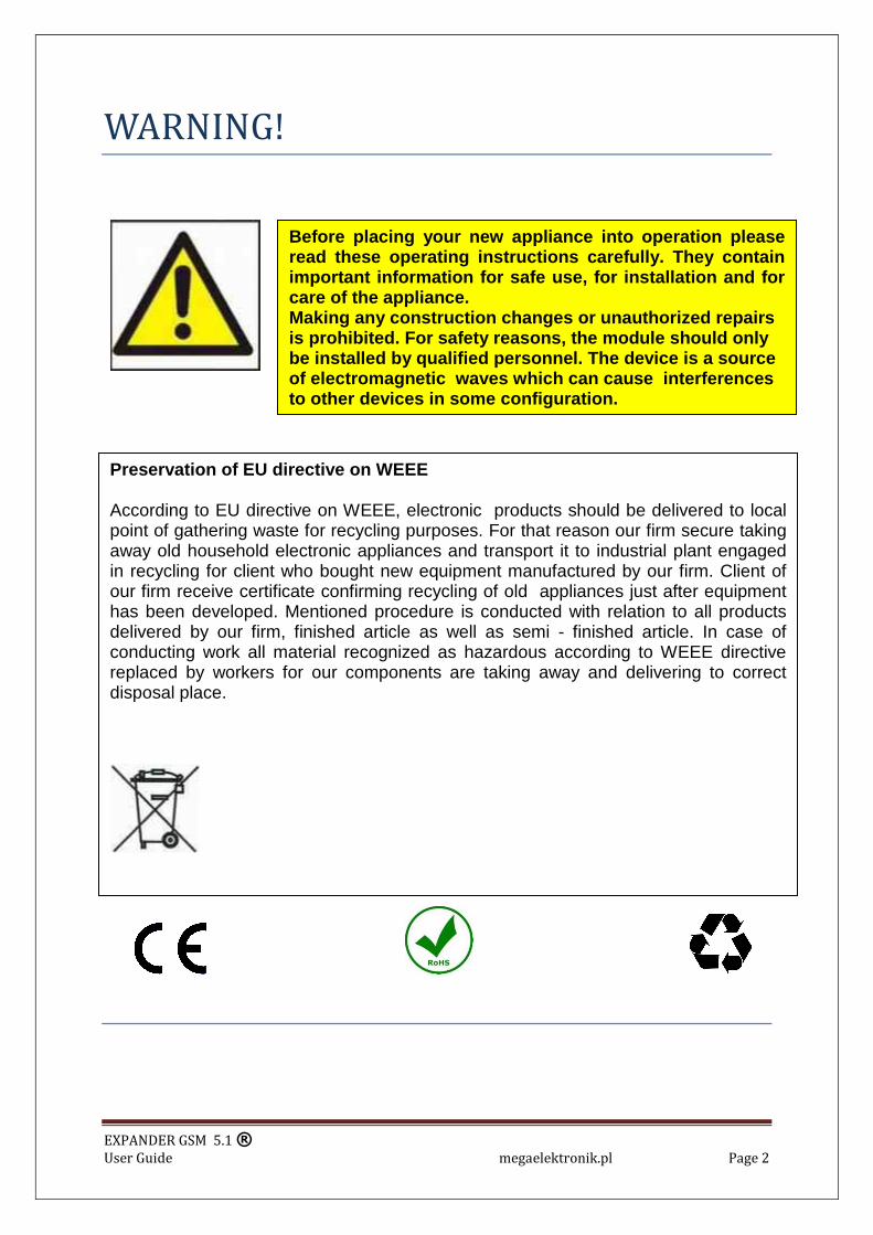
WARNING!
Before placing your new appliance into operation please read these operating instructions carefully. They contain important information for safe use, for installation and for care of the appliance. Making any construction changes or unauthorized repairs is prohibited. For safety reasons, the module should only be installed by qualified personnel. The device is a source of electromagnetic waves which can cause interferences to other devices in some configuration.
Preservation of EU directive on WEEE
According to EU directive on WEEE, electronic products should be delivered to local point of gathering waste for recycling purposes. For that reason our firm secure taking away old household electronic appliances and transport it to industrial plant engaged in recycling for client who bought new equipment manufactured by our firm. Client of our firm receive certificate confirming recycling of old appliances just after equipment has been developed. Mentioned procedure is conducted with relation to all products delivered by our firm, finished article as well as semi - finished article. In case of conducting work all material recognized as hazardous according to WEEE directive replaced by workers for our components are taking away and delivering to correct disposal place.
EXPANDER GSM 5.1 ® User Guide megaelektronik.pl Page 3
DESCRIPTION OF THE MODULE
EXPANDER GSM 5.1 ®
Makes possible send of text, voice and remote control components connected with cell phone network. Moreover, can be independent programmable driver (control panel). Is perfect in monitoring alarm, temperature, fire systems, industry automatic, “intelligent houses”. Cane be used as a control panel to: central heating, air condition, energetic net, vending machines, remote control of computer net and everywhere high security and control rank is needed with easy service. EXPANDER GSM 5.1 ®
Advantages: Cooperation with monitoring stations by: SMS, CLIP, SMS/CLIP, CLIP/SMS. Notification private numbers by: SMS, CLIP, SMS/CLIP, CLIP/SMS. Six inputs having many options. Six outputs having many options. Mode of GSM transmitter, alarm control panel function, time driver. Real-time clock. Events buffer. Events register. Blockade of cost reducing. Impulse meter., Alarm report. Technical report. Remote configuration. „GSM gate” function ®. „Messenger” function ®. „GSM bug” function ®. „Timer” function. „Logic I-0” function. Thermostat GSM Automatic software update. Emergency supply. PC programming. USB build in. Buffer power supply build in.
Set including:
CD-ROM with user guide and program, guarantee,
Program wire, casing, GSM antenna.
EXPANDER GSM 5.1 ® User Guide megaelektronik.pl Page 4
Inputs/outputs descriptions
Joint /component description/meaning
VCC Main supply (+) GND Main supply ground BAT (+) Reserve battery supply. GND Reserve battery ground. OVC Output 12V technical
U, I output. = U, I input. VCC. (sensor supply, voice synthesis etc.)
GND Technical supply ground. IN-1, IN-2 Module inputs:
NO, NC, EOL 2k2, meters IN-3, IN-6 Module inputs:
NO, NC, meters MIC Input (IMS-1) lub SM-1 SP Input ( IGS-1) 1W Input sensor temperature ODW Output. +12V(activated with main supply only)
AWR Output of breakdown signal CL “GSM gate” function ® output. O1-O6 NO, NC module outputs.
SMS Timer, logic function I-O SIM SIM card slot. USB PC programming with USB 1.1, 2.0
interface. ANT GSM Antenna 900/1800/1900Mhz LED2, LED1, GSM Optical signal of work
Supplementary accessories description.
IMS-1 make possible rehearing when the alarm start or voice connection from entitled numbers.
SM-1 speech synthesizer make possible recording and sending voice report when system event occur. After voice connection automatically regenerate. Recorded report is serially regenerated till end of voice connection.
IGS-1 audio module make possible rehearing incoming connection to module. CT-1 sensor temperature range -55C …+125C

EXPANDER GSM 5.1 ® User Guide megaelektronik.pl Page 5
Way of power supply.
Clamp VCC connect to source of constant supply. GND connect to main supply ground. GND connect to battery minus clamp. BAT connect to battery plus clamp. ODV additional sensors power supply output (I,V output. = I,V input). GND additional sensors ground.

EXPANDER GSM 5.1 ® User Guide megaelektronik.pl Page 6
Expander GSM 5.1 ® program installation
EXPANDER GSM 5.1 configuration program is designed for PC computers with WINDOWS 9X/Me/2000/XP/VISTA 32bit operating system. Communication between module and computer is conducted through USB slot (which is build in module and computer). To connect PC and module standard USB cable is used. Installation of program is standard.
1.Start with setup.exe file from enclosed CDROM, can be downloaded from
megaelektronik.pl site also (service branch).
2. Language of installation have to be chosen – available polish and English and
3. Click next.
4. You have accept the agreement and click next.
5. Here we can change folder (not recommended) and click next.
6. We click install and installation will start.
Program has been installed and is located in catalogue.
C:\Program Files\MegaElektronik
WARNING!!!
Power supply of module and connection to the computer
HAVE TO BE DONE ONLY AFTER THE PROGRAM HAD BEEN INSTALLED.
EXPANDER GSM 5.1 ® User Guide megaelektronik.pl Page 7
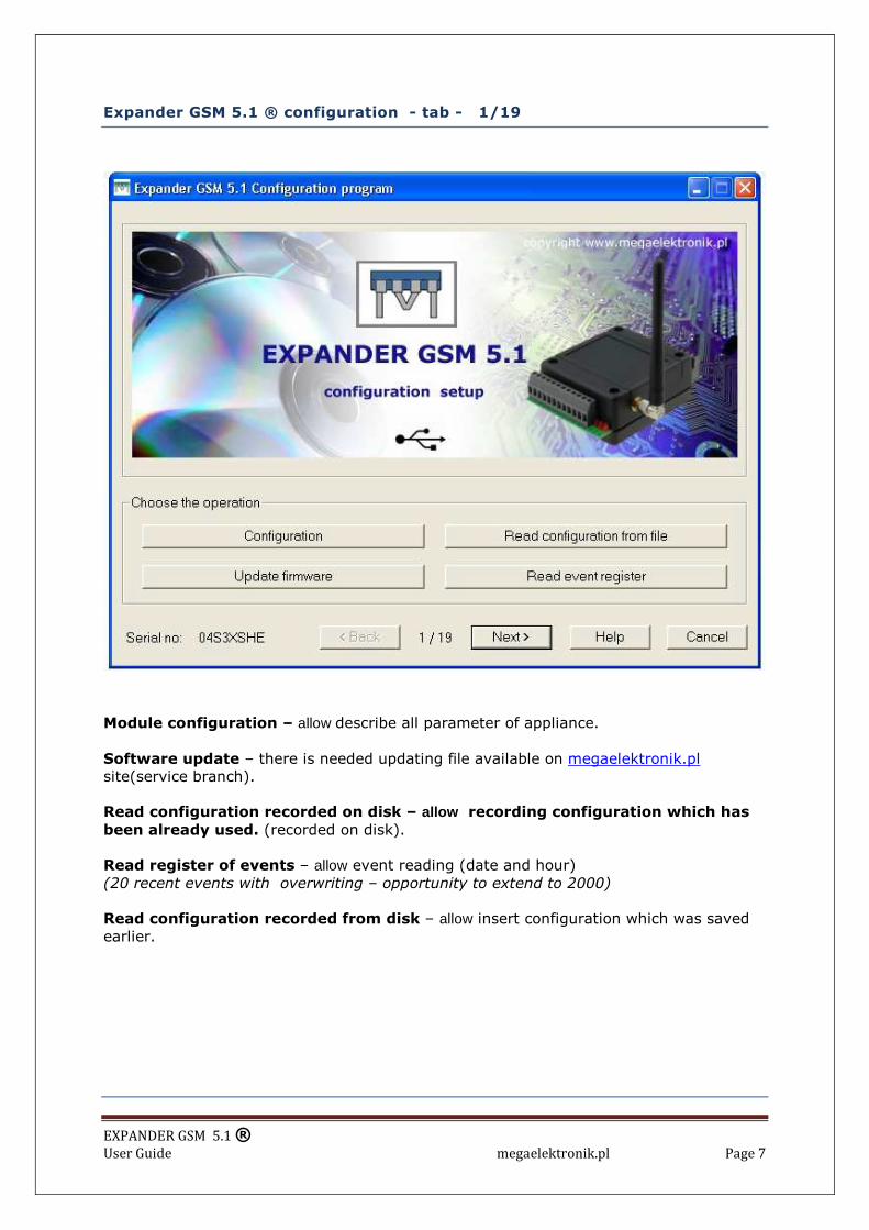
Expander GSM 5.1 ® configuration - tab - 1/19
Module configuration – allow describe all parameter of appliance. Software update – there is needed updating file available on megaelektronik.pl site(service branch). Read configuration recorded on disk – allow recording configuration which has
been already used. (recorded on disk). Read register of events – allow event reading (date and hour) (20 recent events with overwriting – opportunity to extend to 2000)
Read configuration recorded from disk – allow insert configuration which was saved earlier.

EXPANDER GSM 5.1 ® User Guide megaelektronik.pl Page 8
User personal details –tab 2/19
Number of users
We can define number of user entitled to receiving SMS and CLIP signals (ring) whose are send by module. Min. 1 max 8. Format of phone number writing e.g. 422980553, sell phone +48507473767.
Reporting
Time when first report about inputs and outputs status have to be sent and period of time until next report will be send.
Bug
If the number is entitled to that option can connect to module and bug using accessories named IMS – 1, additionally using accessories named IGS – 1 there is opportunity to carry on two – sided conversation.
Remote configuration
Activation of that option allow remote configuration of module by SMS. Reports Activation of that option allow for receiving of reports about module status. Reports include information about inputs and outputs status.

EXPANDER GSM 5.1 ® User Guide megaelektronik.pl Page 9
User personal details – remote change with SMS
SMS content
Module reaction
#### user del (phone number)
Phone number will be deleted from list of informed numbers
#### user report
There will be sent list of current numbers and theirs entitlements.
#### user (phone number) E C B R where? E – echo option C – remote configuration B – bug R- reports Any Letter (option) can be used.
Phone number and its entitlements will be add to list of users.
#### PIN code of SIM card send via SMS (look configuration card No 3) Examples: #### user del +48507473767 Removal user with phone number +48 507 437 767
#### user +48 507473767 E B Addition of user to list of informed user with entitlements ECHO and BUG.
#### user report * Ask module about current phone number list and option of confirming execution of
INQUIRY operation.
#### - PIN code of SIM card via SMS
Number which is source of SMS with new configuration data have to be entitled to
remote configuration option.
EXPANDER GSM 5.1 ® User Guide megaelektronik.pl Page 10
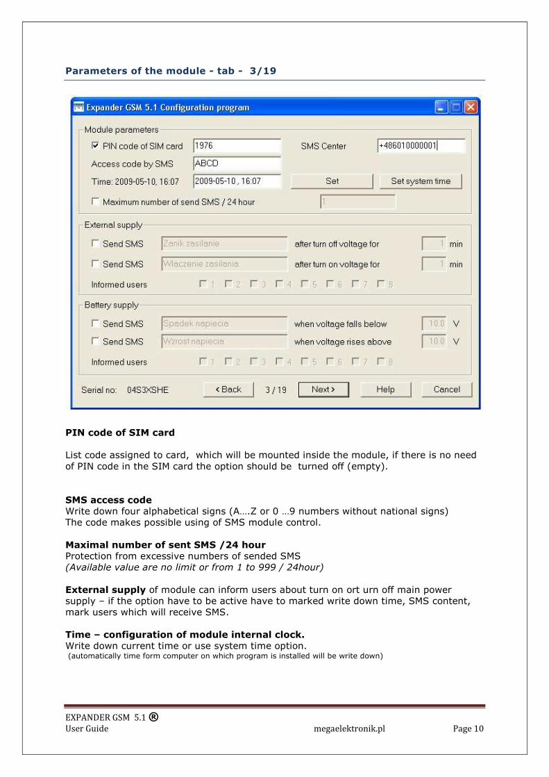
Parameters of the module - tab - 3/19
PIN code of SIM card
List code assigned to card, which will be mounted inside the module, if there is no need of PIN code in the SIM card the option should be turned off (empty).
SMS access code
Write down four alphabetical signs (A….Z or 0 …9 numbers without national signs) The code makes possible using of SMS module control.
Maximal number of sent SMS /24 hour
Protection from excessive numbers of sended SMS (Available value are no limit or from 1 to 999 / 24hour)
External supply of module can inform users about turn on ort urn off main power supply – if the option have to be active have to marked write down time, SMS content, mark users which will receive SMS. Time – configuration of module internal clock.
Write down current time or use system time option. (automatically time form computer on which program is installed will be write down)
EXPANDER GSM 5.1 ® User Guide megaelektronik.pl Page 11
Battery supply module check voltage of battery. When voltage cross value write down inside windows module will send SMS to marked users. To active the option there have to be written SMS content and users should be marked.
Parameters of the module – SMS remote configuration
SMS content
Sort of change
#### code xxxx
Change of SMS access code Where xxxx is the new code
#### hour xx:xx
Internal clock adjustment Where xx:xx is the new hour (time)
####counter on xxx
Adjustment of maximal number of sended SMS/ 24h Where xxx is the number (range from 1 to 999)
####counter off
Turn off maximal numbers of sent SMS – no limit
####batlow xxx (pomiędzy 7.5 i 15.0)
Change of too low voltage of battery after which report of supply will be send where xxx it is voltage (from 7.5 to 15.0)
####power info on xx
Change of time when will be send SMS after turn on main power supply Where xx it is minutes (1... 99)
####power info off
Turn off sending information about vanishing of main power supply
####error GSM on
Turn on output AWR signaling breakdown
####error GSM off
Turn off output AWR signaling breakdown
#### - SMS access code
Number which is source of SMS with new configuration data have to be entitled to
remote configuration option.
EXPANDER GSM 5.1 ® User Guide megaelektronik.pl Page 12
Examples of remote configurations (change of parameters of the module)
1234 code 5678 - change of module access code where 1234 old SMS access code and 5678 new SMS access code
5678 hour 14: 15 – write down of new time (14:15)
5678 counter on 50 - write down of limit SMS /24h
5678 batlow 12.6 – write down new voltage 12,6V, below chich module will send report
abort battery low voltage.
5678 power info on 25 – write down new time, when we will receive message about turn
on main power supply (after 25 minutes)
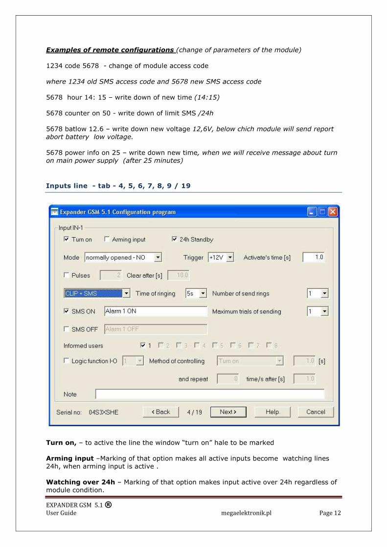
Inputs line - tab - 4, 5, 6, 7, 8, 9 / 19
Turn on, – to active the line the window “turn on” hale to be marked
Arming input –Marking of that option makes all active inputs become watching lines 24h, when arming input is active . Watching over 24h – Marking of that option makes input active over 24h regardless of module condition.

EXPANDER GSM 5.1 ® User Guide megaelektronik.pl Page 13
Mode – way of input reaction to exterior signals. Input can be independently configured as one of types:
• With reference to parameter (resistor 2k2) –concert input IN-1, IN-2
• NO, NC appearance of set signal or vanishing of voltage/earth
• Pulses from 1 to 999 with deleting of pulses after set time from 0,001s to 9999s
Releasing
• +12V (range from 3, 5V to 40V) vanishing (NC) or appearing (NO) of voltage;
• Earth vanishing or appearing;
• Stimulation of time from 0, 01s to 999s;
Way of reaction (stimulation and return)
• SMS
• CLIP
• SMS/CLIP
• CLIP/SMS
There can be assigned option logic I-O to every way of reaction. (each input can control each output)
Time of ringing
Establish how long module have to „ring” when input is stimulated
Maximal trials
Establish number of trials of sending SMS, when obstacle in SMS sending will occur (e.g. with net) SMS as well as CLIP signal. Informed Users
Allow for SMS sending to established sers from marked input.
Control output – Function „Logic I-O”
The function allow for control of each output in one - , two - stable way and repeat control in time range ( from 0, 001 to 9999s) Note – here we can write down information about connection of input. (it is written only in computer )
EXPANDER GSM 5.1 ® User Guide megaelektronik.pl Page 14
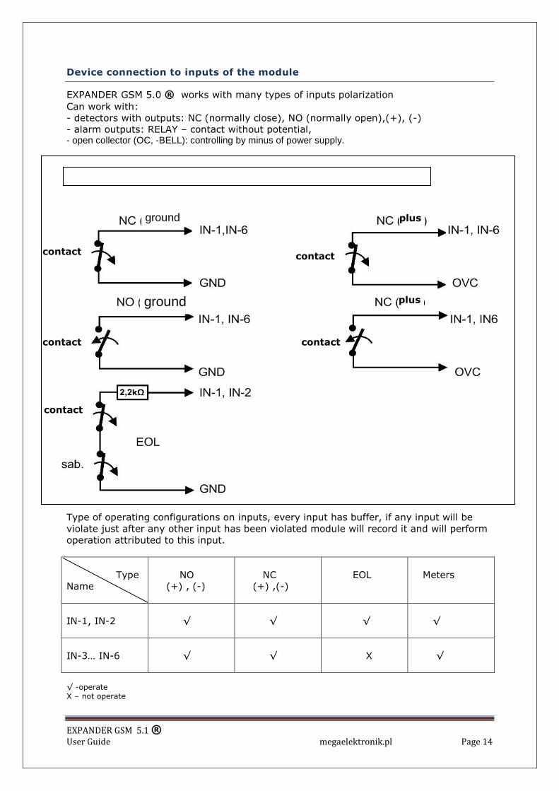
Device connection to inputs of the module
EXPANDER GSM 5.0 ® works with many types of inputs polarization Can work with: - detectors with outputs: NC (normally close), NO (normally open),(+), (-) - alarm outputs: RELAY – contact without potential, - open collector (OC, -BELL): controlling by minus of power supply.
Type of operating configurations on inputs, every input has buffer, if any input will be violate just after any other input has been violated module will record it and will perform operation attributed to this input. Type Name
NO (+) , (-)
NC (+) ,(-)
EOL
Meters
IN-1, IN-2
√
√
√
√
IN-3… IN-6
√
√
X
√
√ -operate X – not operate
EXPANDER GSM 4.0 ® inputs configuration
ground
ground
contact
contact
contact
contact
contact
plus
plus

EXPANDER GSM 5.1 ® User Guide megaelektronik.pl Page 15
Inputs – SMS remote configuration (some functions)
SMS content
Sort of change
input x on
Input turn on
input x off
Turn off (blocade) input No reaction for stimulation signal
input x sms on "new content violation"
Change of SMS sent from specific line. State of stimulation
input x sms off " new content return"
Change of SMS sent from specific line. State of return
input x sms on " new content violation" off " new content return"
Change of SMS sent from specific line. State of stimulation and return at the sime time.
Where x it number of line 1…6
#### - SMS access code
Number which is source of SMS with new configuration data have to be entitled to
remote configuration option.
Addition of mark * (asterisk) just after last letter of SMS
Module will send additional information about (confirming of) success or failure of operation. [inquiry]
EXPANDER GSM 5.1 ® User Guide megaelektronik.pl Page 16
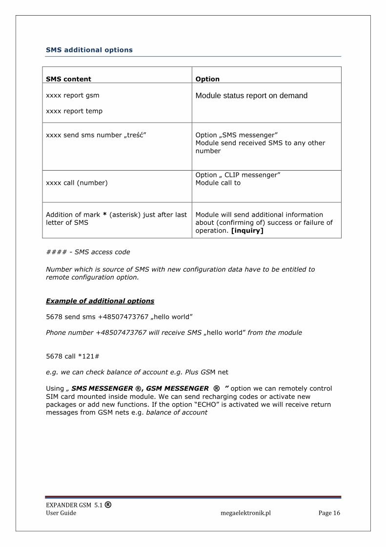
SMS additional options
SMS content
Option
xxxx report gsm xxxx report temp
Module status report on demand
xxxx send sms number „treść”
Option „SMS messenger” Module send received SMS to any other number
xxxx call (number)
Option „ CLIP messenger” Module call to
Addition of mark * (asterisk) just after last letter of SMS
Module will send additional information about (confirming of) success or failure of operation. [inquiry]
#### - SMS access code
Number which is source of SMS with new configuration data have to be entitled to
remote configuration option.
Example of additional options
5678 send sms +48507473767 „hello world” Phone number +48507473767 will receive SMS „hello world” from the module
5678 call *121# e.g. we can check balance of account e.g. Plus GSM net
Using „ SMS MESSENGER ®, GSM MESSENGER ® ” option we can remotely control SIM card mounted inside module. We can send recharging codes or activate new packages or add new functions. If the option “ECHO” is activated we will receive return messages from GSM nets e.g. balance of account

EXPANDER GSM 5.1 ® User Guide megaelektronik.pl Page 17
„GSM gate ® function” – tab – 10/19
„ GSM gate ® function ”
This function allow for non – cost controll output with ring signal – entitled user call to module and change status of CL output. Available arrangements
• Monostable
• Bi stable time range from 0,001s to 99999s
• Output turn off state OC , ON or OFF
• User numbers 75 phone numbers in standard
(possible to wide to 10.000 remote controlling phone numbers)
Note – here there is possibility to write dawn information abort connection of specific line (infromation is written only in computer)

EXPANDER GSM 5.1 ® User Guide megaelektronik.pl Page 18
Outputs and function „ SMS Timer” - tab - 11/19
Initial state – define state of input after configuration of appliance. Control by SMS – define whether specific line can be SMS controlled Automatically turn on at – define time of automatic turn on or turn off input during 24 hour period. Output signaling failure (AWR) – if the option is on module check correctly login to net status. Output become active when failure of SIM card or range accrue.
Turn off sate – establish status of AWR when there is not failure, appearing of failure change status for opposite. Failure must be for time – define time after which failure is signalling from 0, 01 to 9999 s. and time after which from failure output AWR has to be turn off.
Note – here there is possibility to write dawn information abort connection of specific line (infromation is written only in computer)

EXPANDER GSM 5.1 ® User Guide megaelektronik.pl Page 19
Outputs – SMS remote control
SMS content
Module reaction
xxxx output x on
Turn on output
xxxx output x off
Turn off output
xxxx output x on tttttt
Turn on output for programmed time, range from 1… to 9999999 sek. (115 days)
xxxx output x off tttttt
Turn off output for programmed time, range from 1… to 9999999 sek. (115 days)
xxxx output x time on gg:mm off gg:mm
Turn on and turn off output at programmed time input during 24 hour period Where: gg is hours mm to minutes
#### - SMS access code
Number which is source of SMS with new configuration data have to be entitled to
remote configuration option.
Examples of OUTPUT remote control with SMS
5678 output 1 on – change status for opposite output number one (O-1)
5678 output 5 on – change status for opposite output number five (O-5)
5678 output 4 on 9000 - change status for opposite output number four (O-4) for time
9999 sec.
5678 output 2 time on 18: 05 off 06: 00 change status for opposite output number two
O-2 at 18: 05 and again change status for opposite at 06:00.

EXPANDER GSM 5.1 ® User Guide megaelektronik.pl Page 20
Connection of other devices
Type of configurations operated on outputs Function input
Establishing of initial state
NO or NC
Control with SMS
Function Logic I-O
Function GSM GATE
Failure signalization
O1..O6
√
√
√
X
X
AWR
√
X
X
X
√
CL
√
X
X
√
X
√ -operate X – not operate
Connection of other devices
Connection of rely
Connection of

EXPANDER GSM 5.1 ® User Guide megaelektronik.pl Page 21
„Thermostat GSM” tab 12,13,14,16,17 /19

EXPANDER GSM 5.1 ® User Guide megaelektronik.pl Page 22
ON LINE status tab 18 z 19
On-line on this tuck of the programmed can follow on to go out the work of the module and his parameters and state up to date or Option entries allows to send SMS or the signal of bell without the need of stimulating the entrance lines of the module the number of the telephone

EXPANDER GSM 5.1 ® User Guide megaelektronik.pl Page 23
Warning and status of module tab 18 z 19
Warnings – program automatically „catch „ mistakes in arrangements and point where correction should be made, if not module can not be programmed. Save configuration in file – record configuration of module on disc. Phone number, operator, supply voltage, signal quality – show present data of SIM card mounted inside of module. Voltage – present supply voltage of module, GSM signal quality.

EXPANDER GSM 5.1 ® User Guide megaelektronik.pl Page 24
SIM card mounting
Mounting SIM card surgery have been conducted very carefully
1. Insert SIM card into socket see figure (slanted card’s corner in direction of power supply) 2. Gently press down the card simultaneously insert SIM card inside of the module.

EXPANDER GSM 5.1 ® User Guide megaelektronik.pl Page 25
LED – signalization
Updating of firmware
Actualizing file is located on megaelektronik.pl site ( serwis) At the first card choose „Actualize firmware” Load file with * lhx end The operation last a few minutes – don’t interrupt operation
GSM: One flash for 2 sec. module not log in One flash for 6 sec. module correctly log in LED 2 Fast flashing – start of system One flash – receiving of message LED 1 Flashing – sending message or calling LED 1 i LED 2 Alternately flashing Updating of software or unloaded flash of module (wrongly loaded)
EXPANDER GSM 5.1 ® User Guide megaelektronik.pl Page 26
Installment and first activation
EXPANDER GSM 4.0 ® module have to be mounted inside closed rooms, there should be normal humidity of air and temperature in range from -20°C to +50°C. Choosing place of location you should keep in mind:
• Range of GSM net (net of using SIM card);
• Accessibility and distance from source of alarm signals and power;
• Accessibility of room for others and attempts of sabotage;
• Keeping in safe distance from source of interferences (e.g. radio transmitters etc.)
PROCEDURE OF MODULE ACTIVATION
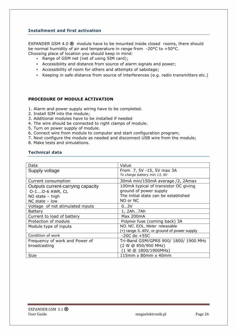
1. Alarm and power supply wiring have to be completed. 2. Install SIM into the module; 3. Additional modules have to be installed if needed 4. The wire should be connected to right clamps of module. 5. Turn on power supply of module. 6. Connect wire from module to computer and start configuration program; 7. Next configure the module as needed and disconnect USB wire from the module; 8. Make tests and simulations. Technical data
Data Value
Supply voltage
From 7, 5V -15, 5V max 3A To charge battery min 13, 6V
Current consumption 30mA min/150mA average /2, 2Amax
Outputs current-carrying capacity O-1….O-6 AWR, CL NO state – high NC state – low
100mA typical of transistor OC giving ground of power supply The initial state can be established NO or NC
Voltage of not stimulated inputs 0…3V Battery 1, 2Ah…7Ah Current to load of battery Max 200mA Protection of module Polymer fuse (coming back) 3A Module type of inputs NO, NC, EOL, Meter releasable
(+) range 3..40V, or ground of power supply Condition of work -20C do +55C Frequency of work and Power of broadcasting
Tri-Band GSM/GPRS 900/ 1800/ 1900 MHz (2 W @ 850/900 MHz) (1 W @ 1800/1900MHz)
Size 115mm x 80mm x 40mm

EXPANDER GSM 5.1 ® User Guide megaelektronik.pl Page 27
Version of product history.
Software version (firmware) Changes 24.11.09 1.0 20.04.09 2.0 10.05.09 3.0
First version Add ON –Line status Thermostat GSM Center SMS