exp 6 thyristor 1phase rect.pdf
TRANSCRIPT
7/27/2019 Exp 6 Thyristor 1Phase Rect.pdf
http://slidepdf.com/reader/full/exp-6-thyristor-1phase-rectpdf 1/6
EEK 471 LAB 6
1
Universiti Sains MalaysiaElectrical Engineering DepartmentAdvanced Power Electronic Laboratory EEK471
Thyristor Single-Phase Bridge Rectifier
OBJECTIVE
To demonstrate the operation of a thyristor single-phase bridge in both rectifier.
INTRODUCTION
Thyristor single-phase bridge
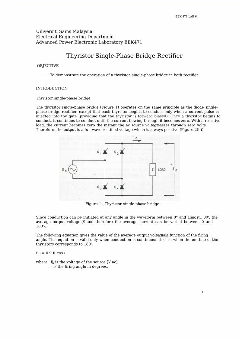
The thyristor single-phase bridge (Figure 1) operates on the same principle as the diode single-phase bridge rectifier, except that each thyristor begins to conduct only when a current pulse isinjected into the gate (providing that the thyristor is forward biased). Once a thyristor begins to
conduct, it continues to conduct until the current flowing through it becomes zero. With a resistiveload, the current becomes zero the instant the ac source voltage E S passes through zero volts.Therefore, the output is a full-wave rectified voltage which is always positive (Figure 2(b)).
Figure 1: Thyristor single-phase bridge.
Since conduction can be initiated at any angle in the waveform between 0° and almost1 80', theaverage output voltage EO, and therefore the average current can be varied between 0 and100%.
The following equation gives the value of the average output voltage EO as a function of the firing
angle. This equation is valid only when conduction is continuous that is, when the on-time of thethyristors corresponds to 180'.
EO = 0.9 ES cos α
where ES is the voltage of the source [V ac]α is the firing angle in degrees.

7/27/2019 Exp 6 Thyristor 1Phase Rect.pdf
http://slidepdf.com/reader/full/exp-6-thyristor-1phase-rectpdf 2/6
EEK 471 LAB 6
2
Figure 2: Output waveforms for a thyristor bridge.
When the load is inductive, the output voltage can be negative for part of the cycle, as shown inFigure 2(c). This is because an inductor stores energy in its magnetic field which is later released.Current continues to flow, and the same thyristors continue to conduct, until all the stored energyis released. Since this occurs some time after the ac source voltage passes through zero, theoutput voltage becomes negative for part of cycle.
The negative part of the output voltage waveform reduces the average output voltage EO. Asseen the previous exercise, a free-wheeling diode can be placed in the circuit to prevent theoutput voltage from going negative (Figure 3). When the output voltage begins to go negative, thefree-wheeling diode conducts. This maintains the output voltage at approximately zero while theenergy stored in the inductor is released. The output voltage waveform is the same as for apurely resistive load (Figure 2(b)), and the average output voltage is therefore greater than itwould be without the free-wheeling diode. The addition of a free-wheeling diode makes the outputcurrent waveform smoother.

7/27/2019 Exp 6 Thyristor 1Phase Rect.pdf
http://slidepdf.com/reader/full/exp-6-thyristor-1phase-rectpdf 3/6
EEK 471 LAB 6
3
Figure 3: Thyristor single-phase bridge with free-wheeling diode.
EQUIPMENTS
EMS 8821 Enclosure Power Supply
EMS 8840-0A PE Power Supply EMS 8841-2A Power Thyristor Module
EMS 9030-30 Thyristor Firing Unit
EMS 8425 Lab-Volt AC Ammeter
EMS 8426 Lab-Volt AC Voltmeter
EMS 8412-05 Lab-Volt DC Voltmeter/Ammeter
EMS 8311 Variable Resistance
EMS 8325 Smoothing Inductor
EMS 9056-15 and EMS 9056-05 Voltage/Current Isolator
24V AC Power Switch
Textronic Oscilloscope
Connection Leads
WARNINGS
The voltages and currents that are used during this lab are larger and rated at 240V AC Line-to-
Neutral with current as high as 20 amps (or higher if circuits are improperly connected). Pleasetake the proper precautions and use your head before touching any circuitry. NEVER change anycircuit connections while the power supply is turned on. Ask the demonstrator to check your connections before turning on the switches. And follow the rating of voltmeters and ammetersgiven to prevent equipments from damaged.
7/27/2019 Exp 6 Thyristor 1Phase Rect.pdf
http://slidepdf.com/reader/full/exp-6-thyristor-1phase-rectpdf 4/6
EEK 471 LAB 6
4
Experiment: Part IControlled bridge supplying a passive load
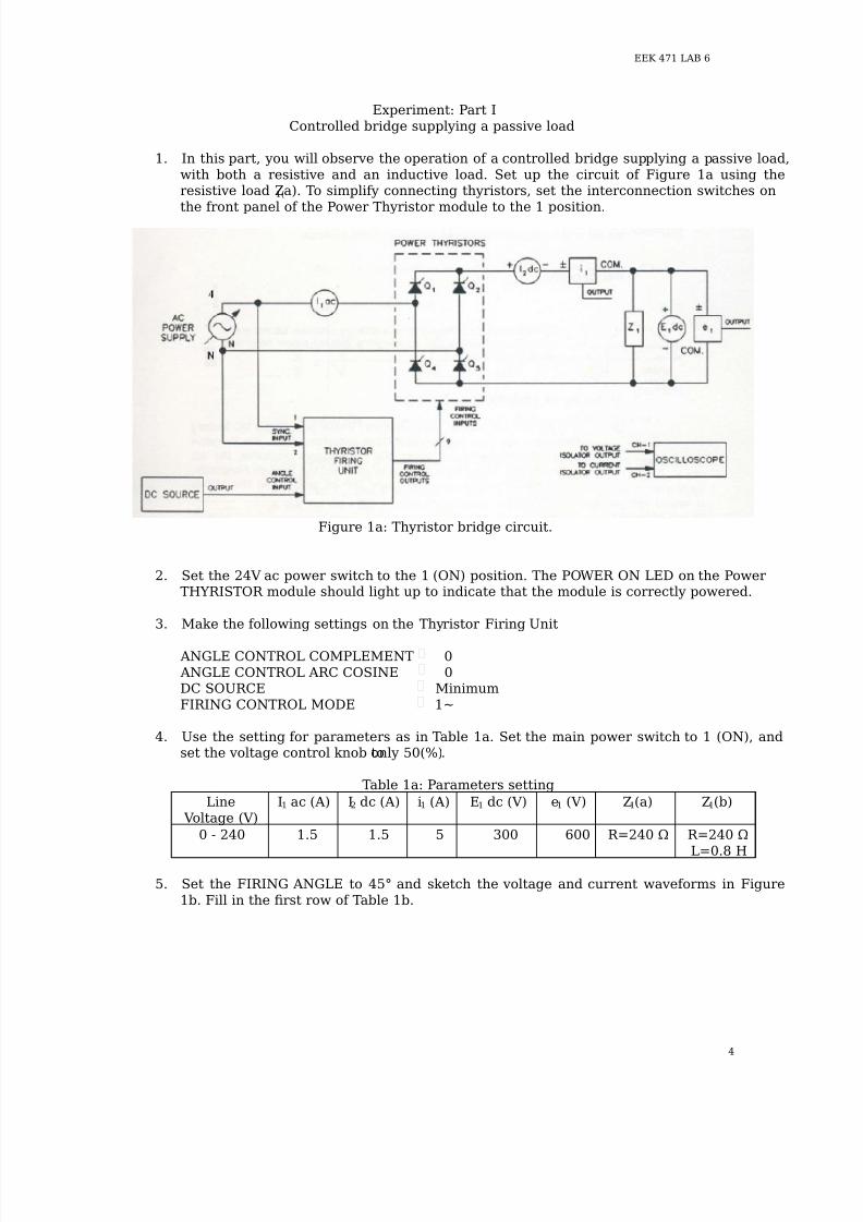
1. In this part, you will observe the operation of a controlled bridge supplying a passive load,with both a resistive and an inductive load. Set up the circuit of Figure 1a using theresistive load Z1(a). To simplify connecting thyristors, set the interconnection switches onthe front panel of the Power Thyristor module to the 1 position.
Figure 1a: Thyristor bridge circuit.
2. Set the 24V ac power switch to the 1 (ON) position. The POWER ON LED on the Power THYRISTOR module should light up to indicate that the module is correctly powered.
3. Make the following settings on the Thyristor Firing Unit
ANGLE CONTROL COMPLEMENT 0 ANGLE CONTROL ARC COSINE 0DC SOURCE MinimumFIRING CONTROL MODE 1~
4. Use the setting for parameters as in Table 1a. Set the main power switch to 1 (ON), andset the voltage control knob to only 50(%).
Table 1a: Parameters setting
LineVoltage (V)
I1 ac (A) I2 dc (A) i1 (A) E1 dc (V) e1 (V) Z1(a) Z1(b)
0 - 240 1.5 1.5 5 300 600 R=240 Ω R=240 Ω
L=0.8 H
5. Set the FIRING ANGLE to 45° and sketch the voltage and current waveforms in Figure1b. Fill in the first row of Table 1b.

7/27/2019 Exp 6 Thyristor 1Phase Rect.pdf
http://slidepdf.com/reader/full/exp-6-thyristor-1phase-rectpdf 5/6
EEK 471 LAB 6
5
Figure 1b: Voltage and current waveforms (α = 45°).
Table 1b: Results
Load Z1 E1 dc (V) I1 dc (A) PO = E1 X I1 (watt)
ConductionAngle (°)
(a) Resistive
(b) Inductive
6. Set the voltage control knob to the 0 % position, set the main power switch to the 0position and turn OFF the power supply. Explain the operation of this circuit.
7. Change the load in the circuit to the inductive load Z1(b) as in Figure 1c. Repeat theprocedure steps necessary to complete Table 1b and Figure 1b.

7/27/2019 Exp 6 Thyristor 1Phase Rect.pdf
http://slidepdf.com/reader/full/exp-6-thyristor-1phase-rectpdf 6/6
EEK 471 LAB 6
6
Figure 1c: Z1(b) connection.
8. Set the voltage control knob to the 0 % position, set the main power switch to the 0position and turn OFF the power supply. Explain the operation of this circuit.
9. What is the difference between this rectifier circuit and the full-wave rectifier circuit.Explain the effect of an inductive load on the voltage and current waveforms and on theconduction angle.
REVIEW QUESTIONS
1. In what direction is active power transferred by a bridge operating in the rectifier mode?
2. What is the role of the inductor in the bridge rectifier circuit.