exp. 2 pneumatic control of a double-acting cylinder
DESCRIPTION
Pneumatic Control of a Double-Acting CylinderTRANSCRIPT
Objective: Students will be able to control of double-acting cylinder, and knowing various types of speed regulation of the piston rod movement of double-acting cylinder.
Pneumatics system performs a variety of tasks, ranging from the very simple to the very complex. Controlling cylinders is one of the most important aspects of pneumatics. For example, two cylinders may be required to operate at the same speed, or a cylinder may need to extend rapidly under no load conditions.
Pre-Lab: the required pneumatic circuit diagrams using the automation studio SW; show the whole connections and components required for each circuit.
In the lab: Connect the circuits and verify their operation. sure that the pressure is 4
bars and is connected correctly. Double check your connections before switching the compressor on.
Direct control of a double-acting cylinder with push-button.
Aim: This exercise provides direct control of double-acting cylinders with manually operated
5/2 directional control valves. In addition, the effect of adjustable spring cushioning in double-acting cylinders can be observed.
Task:- The piston rod of a double-working cylinder (Z1) should extend after actuating a button.- After releasing the button (S1), the piston of the cylinder should retract automatically to
its back position.
1
University Of Jordan Faculty of Engineering & Technology Mechanical Engineering Department
Design of Hydraulic & Pneumatic System Lab Experiments No.2
Pneumatic Control of a Double-acting Cylinder
Introduction
Part one: Control of a double-acting cylinder
Pre-Lab

Lab Experiments Control of Hydraulic and Pneumatic System Lab
List of equipment:Description:
- (01) Air service unit (filter with water separator, pressure regulator and pressure gauge) with 3/2 directional control ball valve
- (02) Distributor, 6-fold- (04) Double-acting cylinder with adjustable spring cushioning- (08) 5/2 directional control valve with push-button Accessories
Figure 1: Direct control of a double-acting cylinder
Conclusion: - The double-acting cylinder can be directly controlled by a ________________________. - In the basic setting (spring position) of a directional valve, port 1 supplied with
compressed air, port 2 is always __________ and port 4 always____________.
2

Lab Experiments Control of Hydraulic and Pneumatic System Lab
Aim:In this exercise, the various types of speed regulation (throttling) of the piston rod
movements of double-acting cylinders with one-way flow control valves are looked at and the effects are observed.
Task: - The cylinder is controlled with a manually operated button (actuator S1). After releasing
the button (S1), the piston of the cylinder should retract automatically to its back position.
List of equipment:Description:
- (04) Double-acting cylinder with adjustable spring cushioning- (08) 5/2 directional control valve with push-button Accessories- (15) Flow control valves with non-return, adjustable
Figure 2: Speed regulation of a double-acting cylinderConclusion:
Referring to figure 2, which circuit demonstrates the following?a. In Circuit (________): The speed of the cylinder piston is restricted when extending.
3
Part two: Speed regulation of a double-acting cylinder

Lab Experiments Control of Hydraulic and Pneumatic System Lab
b. In Circuit (________): The speed of the cylinder piston is restricted when retracting.c. In Circuit (________): Both speed of the cylinder piston are restricted.
Aim:In this exercise we examine how a pneumatically operated impulse valve functions when
controlling a double acting cylinder.
List of equipment:Description:
- (04) Double-acting cylinder with adjustable spring cushioning- (11) 5/2 directional control valve, impulse valve- (15) Flow control valves with non-return, adjustable- (06) 3/2 directional control valve, with manually operated push-button- (07) 3/2 directional control valve, with manually operated push-button, flow in both
directions
Figure 3: Controlling a double-acting cylinder by impulse valveSystem steps:
- Start the system by pressing S1, the cylinder _____________________________________- After releasing S1, the cylinder ________________________________________________- When pressing S2, the cylinder ________________________________________________- If S2 is pressed momentarily, the cylinder _______________________________________
Conclusion:- Impulse Valves are always controlled by ______________________________
4
Part three: Controlling a double-acting cylinder with impulse valve

Lab Experiments Control of Hydraulic and Pneumatic System Lab
- Is impulse valve has a basic setting?
Aim: The displacement-dependent control of a double-acting cylinder by using limit switches in demonstrated in this exercise.
List of equipment:Description:
- (13) 3/2 directional control valves, with roller
Figure 4 : Displacement dependent control of a double-acting cylinderConclusion:
- Design the functional diagram (stroke-time diagram) for the cylinder and the 5/2 directional control valve.
5
Part Four: Displacement dependent control of a double-acting cylinder

Lab Experiments Control of Hydraulic and Pneumatic System Lab
- What are used for a displacement dependent control of a double-acting cylinder?_____________________________________________________________
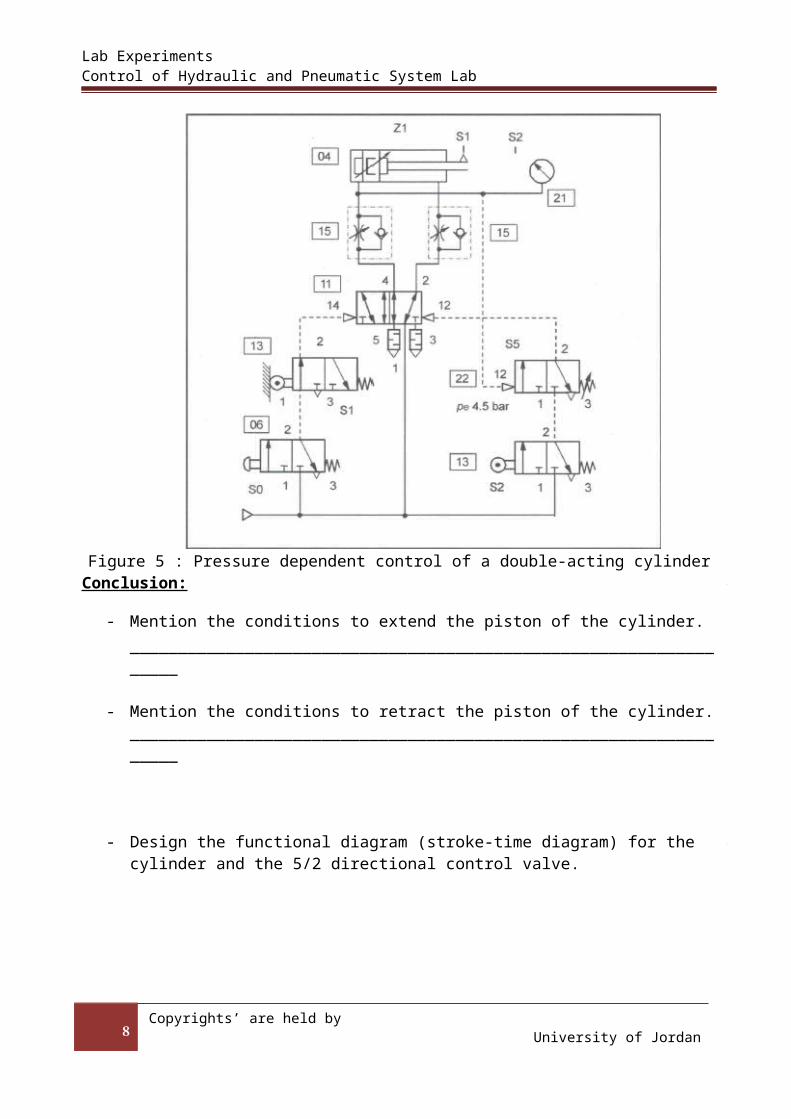
Aim: By using a 3/2 directional control valve with adjustable minimum pressure of response, a
pressure dependent control (and in addition displacement dependent) control of a double acting cylinder is put into effect.
List of equipment:Description:
- (21) Pressure gauge- (22) 3/2 directional control valve, with adjustable operating pressure
Figure 5 : Pressure dependent control of a double-acting cylinderConclusion:
- Mention the conditions to extend the piston of the cylinder.__________________________________________________________________
- Mention the conditions to retract the piston of the cylinder.__________________________________________________________________
6
Part Five: Pressure-dependent control of a double acting cylinder

Lab Experiments Control of Hydraulic and Pneumatic System Lab
- Design the functional diagram (stroke-time diagram) for the cylinder and the 5/2 directional control valve.
Aim: This exercise provides information on time elements used in pneumatic control
technology, their function and application.
List of equipment:Description:
- (9) 3/2 directional control valve, pneumatically operated- (17) 3/2 directional control time-delay valve, adjustable from 0.15- 55 s
Figure 6 : Time dependent control of a double-acting cylinder
7
Part Six: Time-dependent control of a double acting cylinder
Lab Experiments Control of Hydraulic and Pneumatic System Lab
Conclusion:
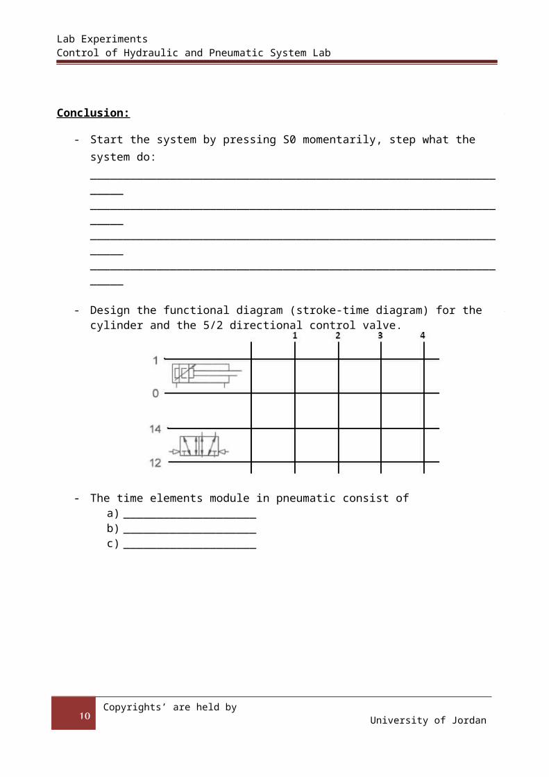
- Start the system by pressing S0 momentarily, step what the system do: ________________________________________________________________________________________________________________________________________________________________________________________________________________________________________________________________________
- Design the functional diagram (stroke-time diagram) for the cylinder and the 5/2 directional control valve.
- The time elements module in pneumatic consist ofa) ____________________b) ____________________c) ____________________
8 Part Seven: Sequential control of a double-acting cylinder

Lab Experiments Control of Hydraulic and Pneumatic System Lab
Aim: This exercise helps to understand sequential controls and provides practical knowledge of
setting up a control system with two pneumatic drives.
Example of application:
Figure 7 : Sequantial control of a double-acting cylinder
Conclusion:
9
Lab Experiments Control of Hydraulic and Pneumatic System Lab
- Start the system by pressing S0 momentarily, step what the system do: ________________________________________________________________________________________________________________________________________________________________________________________________________________________________________________________________________
- Design the functional diagram (stroke-time diagram) for the cylinder and the 5/2 directional control valve.
10