exoplanets imaging camera spectrograph for the european elt
TRANSCRIPT

EPICS for the E-ELT, 20/05/2008, E-ELT DRM, ESO C. Vérinaud 1
Christophe Vérinaud ,Visa Korkiakoski
Laboratoire d’Astrophysique - Observatoire de Grenoble, Franceand
EPICS consortium
ExoPlanets Imaging Camera Spectrograph for the European ELT
Simulations

EPICS for the E-ELT, 20/05/2008, E-ELT DRM, ESO C. Vérinaud 2
Contributors
ESO: M. Kasper , N. Yaitskova , F. Kerber, P. MartinezLAOG: J.-L. Beuzit, V. Korkiakoski, C. VérinaudLAM: K. Dohlen FIZEAU: L. AbeLESIA: P. Baudoz, A. Boccaletti, R. GalicherETH Zurich: H.M. SchmidObs. Padua: R. Gratton, Dino Mesa, J. AntichiUniv. Oxford: N. Thatte, G. Salter, M. TeczaIAC: R. Rebolo, B. Femenia

EPICS for the E-ELT, 20/05/2008, E-ELT DRM, ESO C. Vérinaud 3
Contents
•EPICS scientific objectives
•Overview of EPICS system study
•Simulations: towards end-to-end modeling
•Preliminary results on speckle rejection with IFS

EPICS for the E-ELT, 20/05/2008, E-ELT DRM, ESO C. Vérinaud 4
Direct imaging from ground: today
Imaging: Direct detection of planet photons – Precise determination of orbit, mass, chemical composition, temperature,…
– 5 planet-mass objects discovered (NAOS, VLT) contrast 10-2 10-3
QuickTime™ et undécompresseur TIFF (LZW)
sont requis pour visionner cette image.
QuickTime™ et undécompresseur TIFF (LZW)
sont requis pour visionner cette image.QuickTime™ et un
décompresseur TIFF (non compressé)sont requis pour visionner cette image.
QuickTime™ et undécompresseur TIFF (non compressé)
sont requis pour visionner cette image.

EPICS for the E-ELT, 20/05/2008, E-ELT DRM, ESO C. Vérinaud 5
Direct Imaging from ground: next steps
SPHERE (VLT), GPI (GEMINI), 8-m telescope : 2011– Angular separation: 0.1 < α < 1 arcsec– Contrast (1.6 microns): 10-4 - 10-6
(young gas planets)
α
α : angular separation
= C= Contrast in luminosityII
Parameters for direct imaging:
EPICS (E-ELT), PFI (TMT), 30-40-m telescope :~2020– Angular separation: 0.03 < α < 1 arcsec– Contrast (1.6 microns): 10-7 - 10-9
(mature gas planets and massive rocky planets)

EPICS for the E-ELT, 20/05/2008, E-ELT DRM, ESO C. Vérinaud 6
EPICS Science Objectives
EPICS TLR
•Courtesy: B. Machintosh
•TMT/PFI perf. prediction

EPICS for the E-ELT, 20/05/2008, E-ELT DRM, ESO C. Vérinaud 7
EPICS Science cases
Brightness ratio at Distance [mas]
30 (goal 20) 100 300 Limiting stellar magnitude I band
Science Case 1 10-6 10-6 10-6 9 (goal 10)
Science Case 2 2 10-9
(goal 10-9)10-9
(goal 4 10-10)7 (goal 8)
Science Case 3 10-8 10-9 10-8 7 (goal 8)
Science Case 4 2 10-9
(goal 10-9)10-9
(goal 4 10-10)5 10-10
(goal 2 10-10)5 (goal 6)
• 1. Young self-luminous gas giants in star forming regions or young associations• 2. Detection and characterization of mature jovian gas giants in reflected light• 3. Imaging and characterization of warm Jupiters known by radial velocity• 4. Detection of warm Neptunes and massive rocky planets, ultimately located in habitable zone
TLRs

EPICS for the E-ELT, 20/05/2008, E-ELT DRM, ESO C. Vérinaud 8
EPICS phase A
Phase 1: November 2007 - July-2008
– Intensive Development of modeling toolsE-ELT opticsXAO and coronagraphyInstruments: IFSs, Diff. Pola, Self Coherent CameraSignal extraction (IFS)
– Trade-off studySystem: instruments concept vs. science objectivesCoronagraphy and WF control: review of existing concepts and new ideas
– Phase 2 workplan preparation– Experiments preparation

EPICS for the E-ELT, 20/05/2008, E-ELT DRM, ESO C. Vérinaud 9
EPICS phase A
Phase 2: September 2008- November 2008– Conceptual Design (Baseline + further generation ?)
Opto-mechanical designRisk and cost estimate, Schedule
– Performance analysisDetailed end-to-end simulations for 1st generation EPICSExtrapolation for next generations
– Experiments (FP7 preparatory phase)Extreme AO on an ELT
– HOT bench (ESO): Woofer-Tweeter, co-phasing residuals, etc.– Speckles active correction (LAOG, LESIA)
Coronagraphy: ESO, LESIA, LAM, FIZEAUIntegral Field Spectroscopy
– Oxford Univ.: SLICER IFS– Padua Obs.: BIGRE IFS
Differential polarimetry: ETHZ

EPICS for the E-ELT, 20/05/2008, E-ELT DRM, ESO C. Vérinaud 10
OCTOPUS (ESO/LAOG)
- End-to-End XAO modeling-Correction of atmospheric turbulence (temporally correlated phase screens)
-Correction of instrumental errors on top of AO residuals (post-corono WFS)
Scale of real time simulated : ~seconds(Christophe Vérinaud, Visa Korkiakoski)
PESCA (LAOG)
- End-to-End modeling of EPICS system-Uncorrelated phase screens
-Precise modeling of telescope and EPICS Instrumental optical defects (common and differential errors)
- Precise modeling of instrument, signal extraction and detection noise
(Christophe Vérinaud, Visa Korkiakoski)
Scale of real time simulated : ~hours
Analytical model for high contrast imaging (IAC/LAOG)
-XAO analytical modeling-AO residuals power spectra (à la PAOLA or CAOS_SPHERE)
-Signal extraction analytical modeling- Based on photon noise (SNR/integ. time) and speckle noise (‘hard’ limit)
- →Explore large parameter space beyond EPICS-DRM
(Bruno Femenia, Christophe vérinaud)
Model Adjustments
Model Adjustments
Phase screens generation
EPICS simulations strategy

EPICS for the E-ELT, 20/05/2008, E-ELT DRM, ESO C. Vérinaud 11
EPICS simulations
High contrast imaging modeling is very complex– Needs time to develop code– Needs time to run it
Different level of approximations– The simplest (the one used up to now)
AO Analytical modeling : Photon noise limit imposed by AO halo– 1D model– Need of 2D model cross-checked with simulations (collab. IAC)– Wll be used for de-correlated phase screens generation
The critical issues investigated in priority in phase 1 :Detailed simulations of Fourier Optics: speckle noise limit
–Static aberrations –Coronagraphy–Science Instruments modeling and Signal extraction: IFS

EPICS for the E-ELT, 20/05/2008, E-ELT DRM, ESO C. Vérinaud 12
•Seeing: 0.6″, 10 hours on-source integration (or 30 hours for 1″ seeing)
•Overall efficiency to science detector: 10%
•Observations: dual-band imaging in J-band with 100nm bandwidth
•XAO system main characteristics–Pyramid WFS : optimal for ELT and halo rejection at small angular separations.–0.2-m actuator spacing (~30.000 actuators for 42-m ELT) 3 kHz
•Photon noise limit: assumptions

EPICS for the E-ELT, 20/05/2008, E-ELT DRM, ESO C. Vérinaud 13
Photon noise limit
0 0.5 1 1.5 2
10-10
10-9
10-8
10-7
10-6
Separation [AU]
Con
trast
Gl 581c
Gl 581d
0 0.05 0.1 0.15 0.2 0.25 0.3
10-10
10-9
10-8
10-7
10-6
Separation ["]
EPICS contrast
5σ
Earth size in HZ Jupiter at 5 AUG2V < 6.7 pc < 33.9 pcK0 < 8.2 pc < 25.9 pcM0 < 11.1 pc < 19.5 pc
•10 H integration . Seeing 0.6 arcsec (photon noise limit). 1600-nm, 100nm bandwidth

EPICS for the E-ELT, 20/05/2008, E-ELT DRM, ESO C. Vérinaud 14
Speckle noise
Main contributor: – Static optical errors
Also: speckle lifetime about 1 sec. on a 42-m (not yet implemented)
Error source Nominal values Comments Seg. Piston and tip-tilt
90-nm rms Can be directly scaled by rms improv. ratio
Seg. Mis-figure 30-nm rms Can be directly scaled by rms improv. ratio
EELT 5 mirrors HF sqrt(5) *20 nm rms Can be directly scaled by rms rms improv. ratio
XAO static in band 5-nm rms Typical f0 (phase meas.)
Reflectivity dispersion
1% rms Scaling must be applied on dispersion and not on overall value
•Amplitude errors •Wave-Front errors •Point Spread Function
Error source Nominal values Seg. Piston and tip-tilt
90-nm rms
Seg. M is-figure 30-nm rms
EELT 5 mirrors HF sqrt(5) *20 nm rms
XAO static in band 5-nm rms
Reflectivity dispersion
1% r ms

EPICS for the E-ELT, 20/05/2008, E-ELT DRM, ESO C. Vérinaud 15
Coronagraphic image after XAO
•E-ELT on the moon
•Image at 1000-nm
•Almost « ideal » achromatic coronagraph , not optimized for spider
•E-ELT on Earth
•Seeing : 0.85 arcsec, i0=3ms
•XAO: Pyramid, 200x200, 3 KHz
•SR=80% at 1000-nm
1.2 arcsec

EPICS for the E-ELT, 20/05/2008, E-ELT DRM, ESO C. Vérinaud 16
IFS parameters
Field of View: 2.4 arcsec
Nb of pixels: 1024×1024
Spectral range: ~950-1735 nm
Spectral resolution: R~ 500 - 900 from shortest to longest wavelength (440 monochomatic images)
“IDEAL” IFS: no diffraction or chromatic differential errors

EPICS for the E-ELT, 20/05/2008, E-ELT DRM, ESO C. Vérinaud 17
Beating the speckle noise: IFS
•Coronagraphic image at shortest wave-length + bright point sources
•« Ideal » IFS Coronagraphic images: movie from 950-nm to 1735-nm
1.2 arcsec

EPICS for the E-ELT, 20/05/2008, E-ELT DRM, ESO C. Vérinaud 18
Integrated image: speckle elongation
Integral of 440 monochromatic images from 950 to 1735 nm
EPICS for the E-ELT, 20/05/2008, E-ELT DRM, ESO C. Vérinaud 19
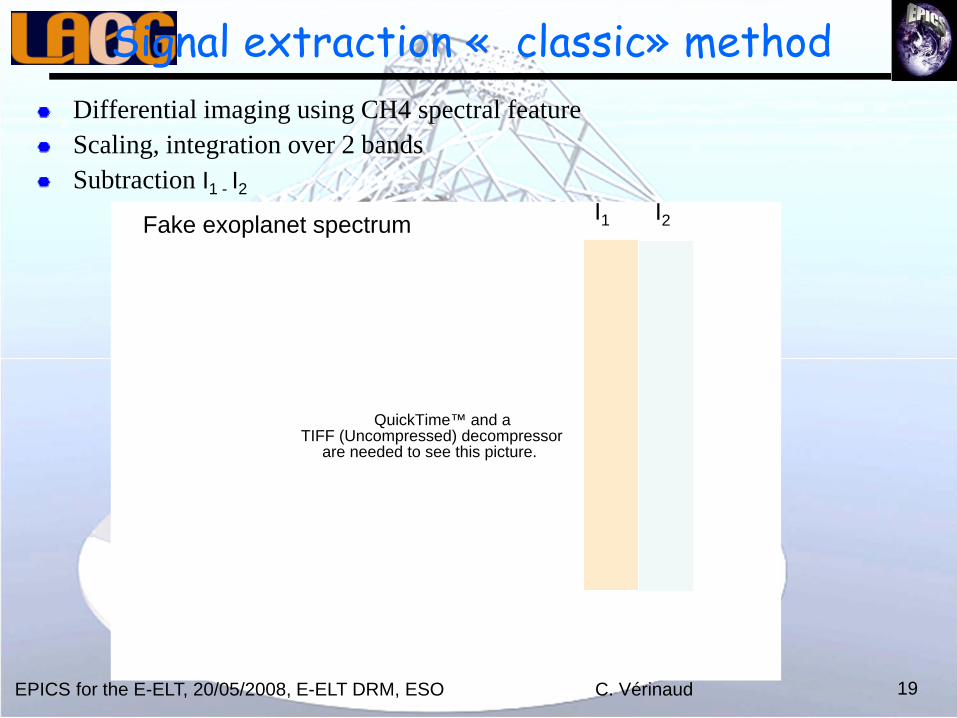
Signal extraction « classic» method Differential imaging using CH4 spectral featureScaling, integration over 2 bandsSubtraction I1 - I2
QuickTime™ and aTIFF (Uncompressed) decompressor
are needed to see this picture.
Fake exoplanet spectrum I1 I2

EPICS for the E-ELT, 20/05/2008, E-ELT DRM, ESO C. Vérinaud 20
Signal extraction method 1•Use of spectral feature (CH4 in H band)
•Symetrical subtraction + Differential imaging in and out absorption and
•10-5
EPICS for the E-ELT, 20/05/2008, E-ELT DRM, ESO C. Vérinaud 21
SCALING
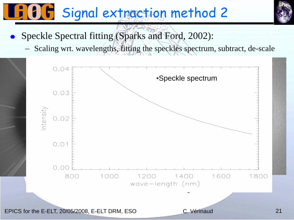
Signal extraction method 2Speckle Spectral fitting (Sparks and Ford, 2002):– Scaling wrt. wavelengths, fitting the speckles spectrum, subtract, de-scale
•Sum of all monochromatic images
•Speckle spectrum

EPICS for the E-ELT, 20/05/2008, E-ELT DRM, ESO C. Vérinaud 22
Signal extraction method 2
1.2 arcsec
•10-5
•10-8
•10-7
•10-9
•10-10
•10-9

EPICS for the E-ELT, 20/05/2008, E-ELT DRM, ESO C. Vérinaud 23
Signal extraction method 2
1.2 arcsec
•10-5
•10-8
•10-7
•10-9
•10-10
•10-9

EPICS for the E-ELT, 20/05/2008, E-ELT DRM, ESO C. Vérinaud 24
Next steps
Effect of Spectral resolution (IFS feasibility)Chromaticity: ADC residuals, chromatic beams shifts, Fresnel diffraction (Talbot)Include Coronagraphy end-to-end model
Apodized Lyot Dual Zone Multi-4 quadrant Binary pupil•Include IFS end-to-end model: LENSLET vs SLICER

EPICS for the E-ELT, 20/05/2008, E-ELT DRM, ESO C. Vérinaud 25
Other Instrument concepts
~V-R band instruments
synchronization (kHz)
modulator
polarizer
demodulating CCD detector
S(t) I(t)Spolarization signal
modulatedpolarization
signal
modulatedintensity
signal
Interferential image
•DIFFERENTIAL POLARIMETER •SELF-COHERENT CAMERA

EPICS for the E-ELT, 20/05/2008, E-ELT DRM, ESO C. Vérinaud 26
Conclusions
Major effort done on simulation work: static speckles– E-ELT optics model well advanced– End-to-end model of IFSs on the way– Signal extraction:
On an ELT speckle elongation is important →IFS with high Resolution looks very promising (achromatic case)
– Next step: include chromaticity (corono, ADC, Talbot, IFS errors…), jitter, AO,etc.
In theory, better the R and λ range, better the speckle rejection– Constrains on IFS are important: > 10Kx10K detector– Trade-off for optimized design is complex: IFS optics, read-noise, etc…
Result presented here are preliminary!– Need to add several other error sources before:
Beeing able to specify EPICS instrument Beeing able to give feed back on Compliance of telescope specifications
– Important effort on signal extraction methods with system priors needed.