exit device dorma 9000 - access...
TRANSCRIPT

DORMA 9000Exit Device

Exit DeviceDORMA 9000
2
DORMA’s 9000 Series heavy-dutyexit devices provide superior dura-bility for high impact applicationssuch as schools, universities, andother institutional or commercialbuildings.The heavy-duty cast chassis provides superior durability, whilethe smooth reduced projection touchbar assembly minimizescatch hazards. The partial length touchpad permits fieldinstallation of options such as cylinder dogging and exit alarm.A full complement of free wheeling lever trim is available in awide range of architectural finishes.
Certification:The DORMA 9000 Series is listed by U.L. and C.U.L. undertheir continuing reinspection programs and conforms tostandards U.L. 10C and U.B.C. 7-2 (1997) positive pressuretesting. The DORMA 9000 Series is BHMA-certified to therequirements of ANSI A156.3 for Grade 1 exit devices.
Miami-Dade County Florida acceptance No. 06-912.05.Expires 01/03/2012.
Specification:All exit devices shall be DORMA 9000 Series rim, mortise,surface, or concealed vertical rod devices. All devices to haveheavy-duty cast chassis. All device touchbar, rail, and coverassemblies shall be constructed of heavy gauge solid wroughtmaterials for true architectural finishes or color coated finisheswhere applicable. The partial-length touchpad assembly shallpermit field installation of options such as cylinder dogging andexit alarm. Non-labeled units to have hex-key dogging standard.Fire rated versions shall be available for labeled applications. All surface vertical rod devices shall have pullman type toplatch bolts and round slidebolt bottom latches. All devices tohave deadlocking latch bolts with 3/4" throw where applicable.All units shall offer a full range of free wheeling operational trim,except mortise devices. All units shall offer optional rigid andclutch-style trim, where applicable. All devices to be furnishedwith appropriate mounting hardware including both wood andmachine screws, as well as sex nuts where required.
Optional Specifications:Non-labeled devices to have cylinder dogging. Mortise cylinderincluded. Specify CD.
All surface/concealed vertical rod devices to have pullman typebottom latch bolt. Specify PB.
All surface/concealed vertical rod devices to have extended toprod up to 10'. Specify ETR.
All surface/concealed vertical rod devices to be furnished lessbottom rod. Specify LB.
Devices to have electric latch bolt retraction to provide remoteaccess from the secure side of door. Can also be used inconjunction with low energy/automatic door operator. Specify ES.(ES must be powered by PS-501 power supply and use ES-105power transfer).
Devices to have a latch monitor to report the latch bolt status.Specify LM.
Devices to be furnished with two switches in the touchbar toprovide notification when touchbar is depressed. Specify MS.
Devices to have latch monitor with monitor switches intouchbar. Specify LM/MS.
Devices to have latch monitor with monitor switches and abypass to permit authorized exit. Specify LM/MS BP.
Devices to have one of the following exit alarm options:battery-powered exit alarm (BPA), battery-powered exit alarm witha 4-minute reset (BPAR), or direct hard-wired exit alarm (DWA).
Devices to use a glass lite shim kit to raise the device from thedoor surface to accommodate glass light molding. SpecifyGK9000.
All devices for labeled wood or composite doors to befurnished with sex bolts. Specify SNB.
All concealed vertical rod exit devices installed in wood doorsto be furnished with appropriate brackets, fasteners, andtemplates for wood door applications. Specify WD (9100 only).
All concealed vertical rod devices installed in aluminum doorsto be furnished with appropriate brackets for aluminum doorapplications. Specify ALD (9100 only).
All devices to use tamper-resistant security screws. Specify TX.All devices to be furnished with rigid trim. Specify R after trim
number.All devices to be furnished with clutch-style lever trim. Specify
C after lever trim number.
Finishes
Warranty:10 Years - Mechanical.2 Years - Electronic integral components and accessories.
The quality managementsystem at the Steeleville,IL facility is certified toISO-9001:2000.*
*DORMA Door Controls Inc., dba: DORMA Architectural Hardware
Architectural Finishes: Powder Coated Finishes:
Brass: 605 (Bright) or 606 (Satin). Aluminum: 689.
Bronze: 611 (Bright), 612 (Satin), or 613 (Oxidized Satin Oil Rubbed).
Bronze: 691 (Dull) or 695 (Dark Duranodic).
Chrome: 625 (Bright) or 626 (Satin). Gold: 696.
Stainless Steel: 630 (Satin).

3
General Information• Partial width touchbar and
rail, chassis, and latch boltcovers are fabricated frombrass, bronze, aluminum,steel, or stainless steel.
• End cap for touchbarassembly furnished incomplementary finish.
• Some models handed depending on outside operating trim and func-tion.
• Most devices easily field-reversible.
• Fasteners provided for metal and wood door applications.
• Free wheeling, vandal-resistant trim standard.
Data & FeaturesHanding
DORMA 9000
Data and Features Model Model Model Model9100 9300 9400 9500
Handing
Outside Outside
Right-Hand Reverse Bevel (RHRB) Left-Hand Reverse Bevel (LHRB)
• Standard Feature • Optional Feature NA - not applicable
U.L. Listed for Hazard • • • •U.L. Listed for Labeled Fire Doors (prefix F) • • • •Size “A” Doors (34"–48") (touchpad 24-5/8") • • • •Size “B” Doors (28"–36") (touchpad 18-5/8") • • • •Size “C” Doors (25"–30") (touchpad 15-5/8") • • • •Door Height up to 7' • NA • NADoor Height up to 8' • NA • NADoor Height up to 10' (specify ETR) • NA • NADoor Thickness 1-3/4" to 2-1/4" • • • •Device Non-Handed NA • NA NADevice Handed but Field Reversible • NA • NADevice Handed, Not Reversible NA NA NA •Hex Key Dogging (non-listed units only) • • • •Cylinder Dogging (non-listed units only) • • • •Round Bottom Slide Bolt • NA • NADeadlocking Pullman Type Bottom Latch Bolt (specify PB) • NA • NALess Bottom Rod (specify LB) • NA • NAElectric Latch Bolt Retraction (specify ES) • • • NAMonitor Switch in Touchbar (specify MS) • • • •Latch bolt Monitor (specify LM) • • • •Latch Monitor/Monitor Switch (specify LM/MS) • • • •Latch Monitor/Monitor Switch with Bypass(specify LM/MS BP)
• • • •
Exit Alarm (specify BPA, BPAR or DWA) • • • •Delayed Egress 15 sec (Specify DE suffix) • • NA •Clutch Style Lever Trim (Specify C suffix) • • • •Magnetic Dogging (Specify MD) • • • •Glass Lite Shim Kit (Specify GK9000) • • • •Security Screws (Specify TX) • • • •Sex Nuts (Specify SNB/Quantity) • • • •Hurricane Code Rated (specify HC) NA • • •

ANSI FunctionDORMA 9000
4
ANSI Function Type 1 Type 2Function Description Rim Exit Device Surface Vertical Rod Exit Device 01 Exit Only – No Trim 9300 or F9300 9400 or F940002 Entrance by trim when 9300 × (trim) 9400 × (trim)
actuating bar is locked V102/V302 V102/V302down. PTT02/PRT02 PTT02/PRT02
YR02R/YT02R/YC02R/YK02R YR02R/YT02R/YC02R/YK02R03 Entrance by trim when 9300 or F9300 × (trim) 9400 or F9400 × (trim)
latch bolt is retracted by VO03/V103/V303, YO03 VO03/V103/V303, YO03key. Key removable only NPT03/PTT03/PRT03 NPT03/PTT03/PRT03when locked. YR03R/YT03R/YC03R/YK03R YR03R/YT03R/YC03R/YK03R
R03/R03IC/C03/C03IC/K03/K03IC R03/R03IC/C03/C03IC/K03/K03ICPOF03HDA —
04 Entrance by trim when CD9300 × (trim) CD9400CD × (trim)latch bolt is retracted VO03/V103/V303, YO03 VO03/V103/V303, YO03by key or set in retracted NPT03/PTT03/PRT03 NPT03/PTT03/PRT03position by key. YR03R/YT03R/YC03R/YK03R YR03R/YT03R/YC03R/YK03R
R03/R03IC/C03/C03IC/K03/K03IC R03/R03IC/C03/C03IC/K03/K03ICPOF03HDA —
05 Entrance by thumbpiece. Key 9300 or F9300 × (trim) 9400 or F9400 × (trim)locks or unlocks thumbpiece. HTT05/HRT05 HTT05/HRT05
06 Entrance by thumbpiece only 9300 or F9300 × (trim) 9400 or F9400 × (trim)when released by key. Key HTT06/HRT06 HTT06/HRT06removable only when locked.
08 Entrance by knob or lever. 9300 or F9300 × (trim) 9400 or F9400 × (trim)Key locks or unlocks YR08/YT08/YC08/YK08 YR08/YT08/YC08/YK08knob or lever. YR08C/YT08C/YC08C YR08C/YT08C/YC08C
R08/R08IC/C08/C08IC/K08/K08IC R08/R08IC/C08/C08IC/K08/K08IC08x08 Entrance by lever. OS or IS F9300 × (trim) —
key locks or unlocks lever. YR08x08 —09 Entrance by knob or lever only 9300 or F9300 × (trim) 9400 or F9400 × (trim)
when released by key. Key YR09/YT09/YC09/YK09 YR09/YT09/YC09/YK09removable only when locked. YR09C/YT09C/YC09C YR09C/YT09C/YC09C
22 Entrance by thumbpiece (no 9300 or F9300 × (trim) 9400 or F9400 × (trim)cylinder). Trim always active. HRT22/HTT22 HRT22/HTT22
23 Entrance by knob or lever 9300 or F9300 × (trim) 9400 or F9400 × (trim)(no cylinder). Trim always YC23/YR23/YT23/YK23 YC23/YR23/YT23/YK23active. C23/R23/K23 C23/R23/K23
ANSI Function Type 3 Type 7/8Function Description Mortise Exit Device Wood/Metal Door Concealed Vertical Rod Exit Device01 Exit Only – No Trim 9500 or F9500 9100 or F910002 Entrance by trim when 9500 × (trim) 9100 × (trim)
actuating bar is locked V102M/V302M V102CV/V302CVdown. PTT02M/PRT02M PTT02CV/PRT02CV
YR02R/YT02R/YC02R/YK02R YR02R/YT02R/YC02R/YK02R03 Entrance by trim when 9500 or F9500 × (trim) 9100 or F9100 × (trim)
latch bolt is retracted by VO03M/V103M/V303M, YO03M VO03CV/V103CV/V303CV, YO03key. Key removable only NPT03M/PTT03M/PRT03M NPT03CV/PTT03CV/PRT03CVwhen locked. YR03MR/YT03MR/YC03MR/YK03MR YR03R/YT03R/YC03R/YK03R
— R03/R03IC/C03/C03IC/K03/K03IC04 Entrance by trim when CD9500 × (trim) CD9100 × (trim)
latch bolt is retracted VO03M/V103M/V303M, YO03M VO03CV/V103CV/V303CV, YO03by key or set in retracted NPT03M/PTT03M/PRT03M NPT03CV/PTT03CV/PRT03CV position by key. YR03MR/YT03MR/YC03MR/YK03MR YR03R/YT03R/YC03R/YK03R
— R03/R03IC/C03/C03IC/K03/K03IC05 Entrance by thumbpiece. Key 9500 or F9500 × (trim) 9100 or F9100 × (trim)
locks or unlocks thumbpiece. HTT05M/HRT05M HTT05CV/HRT05CV06 Entrance by thumbpiece only — 9100 or F9100 × (trim)
when released by key. Key — HTT06CV/HRT06CVremovable only when locked.
08 Entrance by knob or lever. 9500 or F9500 × (trim) 9100 or F9100 × (trim)Key locks or unlocks YR08M/YT08M/YC08M/YK08M YR08/YT08/YC08/YK08knob or lever. YR08MC/YT08MC/YC08MC YR08C/YT08C/YC08C
— R08/R08IC/C08/C08IC/K08/K08IC09 Entrance by knob or lever only — 9100 or F9100 × (trim)
when released by key. Key — YR09/YT09/YC09/YK09removable only when locked. — YR09C/YT09C/YC09C
22 Entrance by thumbpiece (no 9500 or F9500 × (trim) 9100 or F9100 × (trim)cylinder). Trim always active. HRT22M/HTT22M HRT22CV/HTT22CV
23 Entrance by knob or lever 9500 or F9500 × (trim) 9100 or F9100 × (trim)(no cylinder). Trim always YC23M/YR23M/YT23M/YK23M YC23/YR23/YT23/YK23active. — C23/R23/K23

5
LM × F 9400B × V103 × 426/439 × RHR × 630
Options Model Trim Strikes Hand Finish
Fire Rated for labeled fire doors
Device Size
Latch Monitor
9000 Series Exit Device
How to OrderTo order, list options, model number, trim, strikes, hand,and finish.
(CD) Cylinder Dogging(ES) Latch Retraction (9100, 9300, 9400)(ETR) Top Rod Extension (9100,9400)(GK9000) Glass Lite Shim Kit(LB) Less Bottom Rod (9100, 9400)(LM) Latch Monitor (MD) Magnetic Dogging(MS) Monitor Switch(LM/MS) Latch Monitor/Monitor Switch(LM/MS BP) Latch Monitor/Monitor Switch with Bypass(DE) Delayed Egress – 15 sec (9100, 9300, 9500)(PB) Pullman Bottom Latch – vertical rod only(SNB) Sex Nuts – specify quantity(WD) Wood Door Package (9100 only)(ALD) Aluminum Door Brackets (9100)(TX) Security Screws(HC) Hurricane Code Rated (9300, 9400, and 9500)
Options: (R) Rigid Trim(C) Clutch Style Lever Trim(BPA) Battery Powered Exit Alarm(BPAR) Battery Powered Exit Alarm, (4) minute reset(DWA) Direct Wired Exit Alarm
* Designates minimum U.L. listing for wood doors over 8' in height. Listings for 90 minutes or greater may be applicable throughother listing agencies dependent upon the wood door manufacturer’s current listing. Contact wood door manufacturer for details.
How to OrderApplications and Listings
DORMA 9000
Model DoorMaterial
Max. DoorOpening Door Ratings Applications
Single DoorsConcealed Vertical Rod9100
Wood/Steel 4' × 10' Devices are panic listed onlyConcealed(2) point latchingConcealed Vertical Rod
F9100
Steel 4' × 10' 3 Hour
Wood 4' × 10' 1-1/2 Hour
Concealed Vertical Rod(Less Bottom Rod)9100 LB
Wood/Steel 4' × 10' Devices are panic listed onlyConcealed(1) point latchingConcealed Vertical Rod
(Less Bottom Rod)F9100 LB
Steel 4' × 10' 3 Hour
Wood 4' × 10' 1-1/2 Hour
Rim9300
Wood/Steel 4' × 8' Devices are panic listed onlySurface applied(1) point latchingRim
F9300Steel 4' × 8' 3 Hour
Wood 4' × 8' 1-1/2 Hour
Surface Vertical Rod9400
Wood/Steel 4' × 10' Devices are panic listed onlySurface applied(2) point latchingSurface Vertical Rod
F9400
Steel 4' × 10' 3 Hour
Wood 4' × 10' 1-1/2 Hour
Surface Vertical Rod(Less Bottom Rod)9400 LB
Wood/Steel 4' × 10' Devices are panic listed onlySurface applied(1) point latchingSurface Vertical Rod
(Less Bottom Rod)F9400 LB
Steel 4' × 10' 3 Hour
Wood 4' × 10' 1-1/2 Hour
Mortise9500 Wood/Steel 4' × 10' Devices are panic listed only
Mortised(1) point latchingMortise
F9500Steel 4' × 10' 3 Hour
Wood 4' × 8' 1-1/2 Hour
Wood 4' × 10' *1/3 Hour

Applications and ListingsDORMA 9000
6
Notes:1. Fire rated pairs using Less Bottom Rod devices require the supplied door popper. With the absence of bottom rods, the popper holds the bottoms of the doors together in the event of fire.
2. Pairs of doors swinging in the same direction cannot use two vertical rod exit devices with an overlapping astragal aspairs of doors rated greater than 1-1/2 hours require a steel overlapping astragal. Currently, no door manufacturers offerover 90 minutes with doors swinging in the same direction.
ModelDoor
MaterialMax. DoorOpening
Door Ratings Applications
Pair of Doors with Removable MullionRim × Rim9300 × 9300 Wood/Steel 8' × 8' Devices are panic listed only (2) independent
active doors withremovable mullion(1) point latching
Rim × RimF9300 × F9300
Steel 8' × 8' 3 Hour
Wood 8' × 8' 1-1/2 Hour
Pair of DoorsConcealed Vertical Rod9100 × 9100 Wood/Steel 8' × 10' Devices are panic listed only
(2) independent doorswith (2) point latching
(swing same direction)
Concealed Vertical RodF9100 × F9100
Steel 8' × 10' 1-1/2 Hour2
Wood 8' × 8' 1-1/2 Hour
Wood 8' × 10' 1-1/2 Hour
Concealed Vertical Rod9100 × 9100 Wood/Steel 8' × 10' Devices are panic listed only
(2) independent doorswith (2) point latching
(swing opposite direction)
Concealed Vertical RodF9100 × F9100
Steel 8' × 10' 3 Hour
Wood 8' × 8' 1-1/2 Hour
Wood 8' × 10' 1-1/2 Hour
Concealed Vertical Rod(Less Bottom Rod)9100 LB × 9100 LB
Wood/Steel 8' × 10' Devices are panic listed only(2) independent doorswith (1) point latching
(swing same direction)
Concealed Vertical Rod(Less Bottom Rod)F9100 LB × F9100 LB
Steel 8' × 10' 1-1/2 Hour1,2
Wood 8' × 10' 1-1/2 Hour1
Concealed Vertical Rod(Less Bottom Rod)9100 LB × 9100 LB
Wood/Steel 8' × 10' Devices are panic listed only(2) independent doorswith (1) point latching
(swing opposite direction)
Concealed Vertical Rod(Less Bottom Rod)F9100 LB × F9100 LB
Steel 8' × 10' 3 Hour1
Wood 8' × 10' 1-1/2 Hour1
Surface Vertical Rod9400 × 9400 Wood/Steel 8' × 10' Devices are panic listed only
(2) independent doorswith (2) point latching
(swing same direction)
Surface Vertical RodF9400 × F9400
Steel 8' × 10' 1-1/2 Hour2
Wood 8' × 8' 1-1/2 Hour
Wood 8' × 10' 1-1/2 Hour

7
ModelDoor
MaterialMax. DoorOpening
Door Ratings Applications
Pair of Doors (continued)Surface Vertical Rod9400 × 9400 Wood/Steel 8' × 10' Devices are panic listed only
(2) independent doorswith (2) point latching
(swing opposite direction)
Surface Vertical RodF9400 × F9400
Steel 8' × 10' 3 Hour
Wood 8' × 8' 1-1/2 Hour
Wood 8' × 10' 1-1/2 Hour
Surface Vertical Rod(Less Bottom Rod)9400 LB × 9400 LB
Wood/Steel 8' × 10' Devices are panic listed only(2) independent doorswith (1) point latching
(swing same direction)
Surface Vertical Rod(Less Bottom Rod)F9400 LB × F9400 LB
Steel 8' × 10' 1-1/2 Hour1,2
Wood 8' × 10' 1-1/2 Hour1
Surface Vertical Rod(Less Bottom Rod)9400 LB × 9400 LB
Wood/Steel 8' × 10' Devices are panic listed only
(2) independent doorswith (1) point latching
(swing opposite direction)
Surface Vertical Rod(Less Bottom Rod)F9400 LB × F9400 LB
Steel 8' × 10' 3 Hour1
Wood 8' × 10' 1-1/2 Hour1
Rim × Surface Vertical Rod9300 × 9400
Wood/Steel 8' × 8' Devices are panic listed only
(2) independent doorswith (1) and (2) pointlatching
(swing same direction)
Rim × ConcealedVertical Rod9300 × 9100
Wood/Steel 8' × 8' Devices are panic listed only
(2) independent doorswith (1) and (2) pointlatching
(swing same direction)
Mortise × SurfaceVertical Rod9500 × 9400
Wood/Steel 8' × 10' Devices are panic listed only
(2) independent doorswith (1) and (2) pointlatching
(swing same direction)
Mortise × SurfaceVertical RodF9500 × F9400
Steel 8' × 10' 3 Hour
Wood 8' × 8' 1-1/2 Hour
Wood 8' × 10' 1-1/2Hour
Mortise × ConcealedVertical Rod9500 × 9100
Wood/Steel 8' × 10' Devices are panic listed only
(2) independent doorswith (1) and (2) pointlatching
(swing same direction)
Mortise × ConcealedVertical RodF9500 × F9100
Steel 8' × 10' 3 Hour
Wood 8' × 8' 1-1/2 Hour
Wood 8' × 10' 1-1/2Hour

Exit DeviceDORMA 9100
9100/F9100 Concealed Vertical Rod Exit DevicesThe 9100 Concealed Vertical Rod and the F9100 Series ConcealedVertical Rod Fire Exit Devices are excellent choices where barrier-freecodes, aesthetics, or the potential for vandalism require concealmentof the vertical rod. They are panic and fire-listed (three-hour steel firedoor applications) and feature a simplified adjustment mechanism thatprovides ease of installation and reduced service requirements.
ModelNumber
Function Operation Trim Model Numbers
9100F9100
01 Exit Only(no trim)
9100F9100
DT Dummy Trim VODTCV NPTDTCV YODT
9100 02 Entrance by trim whenactuating bar is locked down.
V102CVV302CV
PTT02CVPRT02CV
9100F9100
03 Entrance by trim when latchbolts are retracted by key. Keyremovable only when locked.
VO03CV V103CVV303CV
NPT03CV PTT03CVPRT03CV
YO03
CD9100 04 Entrance by trim when latchbolts are retracted by key or set in a retracted positionby key.
VO03CV V103CVV303CV
NPT03CV PTT03CVPRT03CV
YO03
9100F9100
05 Entrance by thumbpiece. Keylocks or unlocks thumbpiece.
HTT05CVHRT05CV
9100F9100
06 Entrance by thumbpiece onlywhen released by key. Keyremovable only when locked.
HTT06CVHRT06CV
9100F9100
08 Entrance by knob or lever.Key locks or unlocks knob or lever.
YK08 YR08YT08YC08YG08
9100F9100
09 Entrance by knob or lever onlywhen released by key. Keyremovable only when locked.
YK09 YR09YT09YC09YG09
9100 22 Entrance by thumbpiece and pull or pull only whenactuating bar is locked down.
HTT22CVHRT22CV
9100F9100
23 Entrance by knob or lever (no cylinder). Knob or leveralways active.
YK23 YR23YT23YC23YG23
8
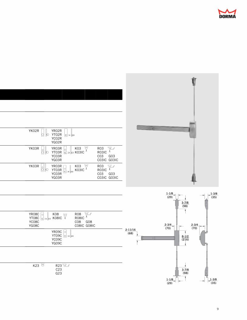
9
1-1/8(29)
2-3/4(70)2-11/16
(68)8-1/2(216)
3-7/8(98)
1-3/8(35)
1-1/8(29)
3-7/8(98)
1-3/8(35)
2-3/4(70)
YK02R YR02RYT02RYC02RYG02R
YK03R YR03RYT03RYC03RYG03R
K03 K03IC
R03R03ICC03C03IC
G03G03IC
YK03R YR03RYT03RYC03RYG03R
K03 K03IC
R03R03ICC03C03IC
G03G03IC
YR08CYT08CYC08CYG08C
K08 K08IC
R08R08ICC08C08IC
G08G08IC
YR09CYT09CYC09CYG09C
K23 R23C23G23

StrikesMinimum Stile
DORMA 9100
10
No. 418 - Top Strike 9100/F9100, 9100LB/F9100LB No. 439 - Bottom Strike 9100/F9100
Standard Strikes
No. 419 - Top Strike for use with wood frames No. 431 - Recessed Bottom Strike for use withoptional pullman bottom latch bolt
Optional Strikes
1-5/8(41)
13/16(21)
13/16(20)
2(51)
3/32(2)1-1/2
(38)
1(25)
3/32(2)
5/8(16)
I.D.
3/4(19)
3/4(19)
1-13/16(46)
13/16(21)
2(51)
9/16(14)
1-3/8(35)
3/32(2)1-1/2
(38)
1-3/4(44)
1-3/4(44)
5/32(4)
1(25)

11
No. 340 - Flat Bottom Strike; Optional for use with standardbottom slidebolt
Optional Strikes
Pair Concealed Vertical Rod Concealed Vertical Rod × Mortise
Minimum Stile and Vertical Reference
2(51)
1(25)
3/32(2)
Edge of Door
Minimum Stile
Vertical Reference2-3/4(70)
4-3/16(106)
4-3/16(106)
2-3/4(70)
Edge of Door
Minimum Stile
Vertical Reference

Exit DeviceDORMA 9300
9300/F9300 Rim Exit DevicesThe 9300 and F9300 present a simple, heavy-duty, easilyinstalled solution where high quality panic and fire-listedhardware is needed. The patented exit devices in the 9300 and F9300 Series are available in a full range of finishes and trim options. The F9300 Series devices carry an “A” label forthree-hour steel fire door applications.
ModelNumber
Function Operation Trim Model Numbers
9300F9300
01 Exit Only(no trim)
9300F9300
DT Dummy Trim VODT NPTDT YODT
9300 02 Entrance by trim when actuating bar is locked down.
V102V302
PTT02PRT02
9300F9300
03 Entrance by trim when latchbolt is retracted by key. Keyremovable only when locked.
VO03 V103V303
NPT03 PTT03PRT03
YO03
CD9300 04 Entrance by trim when latchbolt is retracted by key or set ina retracted position by key.
VO03 V103V303
NPT03 PTT03PRT03
YO03
9300F9300
05 Entrance by thumbpiece. Keylocks or unlocks thumbpiece.
HTT05HRT05
9300F9300
06 Entrance by thumbpiece onlywhen released by key. Keyremovable only when locked.
HTT06HRT06
9300F9300
08 Entrance by knob or lever. Keylocks or unlocks knob or lever.
YK08 YR08YT08YC08YG08
F9300 08x08 Entrance by lever. Outside orinside key locks or unlockslever.
YR08x08
9300F9300
09 Entrance by knob or lever onlywhen released by key. Keyremovable only when locked.
YK09 YR09YT09YC09YG09
9300 22 Entrance by thumbpiece andpull or pull only when actuating bar is locked down.
HTT22HRT22
9300F9300
23 Entrance by knob or lever (no cylinder). Knob or leveralways active.
YK23 YR23YT23YC23YG23
12

13
2-11/16(68)
2-3/4(70)
8-1/2(216)
2-3/4(70)
YK02R YR02RYT02RYC02RYG02R
YK03R YR03RYT03RYC03RYG03R
K03 K03IC
R03R03ICC03C03IC
G03G03IC
YK03R YR03RYT03RYC03RYG03R
K03 K03IC
R03R03ICC03C03IC
G03G03IC
YR08CYT08CYC08CYG08C
K08 K08IC
R08R08ICC08C08IC
G08G08IC
YR09CYT09CYC09CYG09C
K23 R23C23G23
POF03HDA
POF03HDA

StrikesMinimum Stile
DORMA 9300
14
No. 430 - Box Strike with 9300
Standard Strike
No. 486 - Roller Strike for use with 9300 No. 320 - Overlap Strike for use with 9300Not Fire Rated
Optional Strikes
29/32(23)
1-57/64(48)
1/2(13)
1-25/32(45)
29/64(12)
1-1/8(29)
1-13/16(46)
2-3/8(60)
5/8(16)
3/4(19)
1-1/2(38)
3/8(10)
2(51)
2-1/8(54)
15º
1-1/16(27)
No. 463 - Standard Strike with 9300 and F9300
1-5/8(41)
4-1/2(114)
3-3/4(95)
3/4(19)
Optional Strike

15
Single Door Pair Doors with Mullion
Minimum Stile and Vertical Reference
Rim and Vertical RodPair Doors with No Mullion
Edge of Door
Minimum Stile
2-13/16(71)
4-1/4(108)
Vertical Reference
Overlap Strike
Edge of Door4
(102)
2-1/2(64)
Vertical Reference
Minimum Stile
Edge of Door
Minimum Stile
Mullion
Vertical Reference
Mullion Strike Vert. Ref. Min. Stile
1310 All 2-3/4" (70) 4-3/16" (106)
1330 All 2-15/16" (75) 4-3/8" (111)
F1300 All 3-1/4" (83) 4-11/16" (119)F1340KR

Exit DeviceDORMA 9400
9400/F9400 Surface Vertical Rod Exit DevicesThe 9400 and F9400 provide heavy-duty, secure, two-pointlatching at the top and bottom of the opening. Both the 9400and F9400 Series feature a patented latch design for reliable,secure operation. The F9400 devices are U.L.-listed for three-hour steel fire door applications.
16
ModelNumber
Function Operation Trim Model Numbers
9400F9400
01 Exit Only(no trim)
9400F9400
DT Dummy Trim VODT NPTDT YODT
9400 02 Entrance by trim when actuating bar is locked down.
V102V302
PTT02PRT02
9400F9400
03 Entrance by trim when latchbolts are retracted by key. Keyremovable only when locked.
VO03 V103V303
NPT03 PTT03PRT03
YO03
CD9400 04 Entrance by trim when latchbolt is retracted by key or set ina retracted position by key.
VO03 V103V303
NPT03 PTT03PRT03
YO03
9400F9400
05 Entrance by thumbpiece. Keylocks or unlocks thumbpiece.
HTT05HRT05
9400F9400
06 Entrance by thumbpiece onlywhen released by key. Keyremovable only when locked.
HTT06HRT06
9400F9400
08 Entrance by knob or lever.Key locks or unlocks knob orlever.
YK08
9400F9400
09 Entrance by knob or lever onlywhen released by key. Keyremovable only when locked.
YK09
9400 22 Entrance by thumbpiece andpull or pull only when actuating bar is locked down.
HTT22HRT22
9400F9400
23 Entrance by knob or lever (no cylinder). Knob or leveralways active.
YK23

17
1-1/4(32)
2-3/4(70)
8-1/2(216)
1-9/16(40)
2-3/4(70)
4-3/8(111)
1-1/4(32)
1-9/16(40)
2-11/16(68)
1/2(13)
4-3/8(111)
YK02R YR02RYT02RYC02RYG02R
YK03R YR03RYT03RYC03RYG03R
K03 K03IC
R03R03ICC03C03IC
G03G03IC
YK03R YR03RYT03RYC03RYG03R
K03 K03IC
R03R03ICC03C03IC
G03G03IC
YR08YT08YC08YG08
YR08CYT08CYC08CYG08C
K08 K08IC
R08R08ICC08C08IC
G08G08IC
YR09YT09YC09YG09
YR09CYT09CYC09CYG09C
YR23YT23YC23YG23
K23 R23C23G23

StrikesMinimum Stile
DORMA 9400
18
No. 426 - Top Strike 9400/F9400, 9400LB/F9400LB No. 439 - Bottom Strike 9400/F9400
Standard Strikes
No. 426A - Top strike with angle bracket for use with flushdoor and frame
No. 340 - Flat bottom strike for use with standard bottom slidebolt
Optional Strikes
1/2(13)
2(51)
3/4(19)
1-1/2(38
1(25)
1(25)
3/32(2)
5/8(16)
I.D.
3/4(19)
3/4(19)
1-1/2(38)
2(51)
2-1/4(57)
2(51)
1(25)
3/32(2)

19
No. 416V - Surface mount bottom strike for use withoptional pullman bottom latch
No. 431 - Recessed bottom strike for use with optionalpullman bottom latch bolt
Optional Strikes
Vertical Rod × Mortise Pair Vertical Rod
Minimum Stile and Vertical Reference
1-1/8(29)
2-3/8(60)
1/2(13)
1-13/16(46)
5/8(16)
Edge of Door
Minimum Stile
Vertical Reference
4-3/16(106)
2-3/4(70)
1-3/4(44)
1-3/4(44)
5/32(4)
1(25)
Edge of Door
Vertical Reference
4-3/16(106)
2-3/4(70)
Minimum Stile

ModelNumber Function Operation Trim Model Numbers
9500F9500
011
Exit Only(no trim)
9500F9500
DT1
Dummy Trim VODT NPTDT YODT
9500 021
Entrance by trim when actuating bar is locked.
V102MV302M
PTT02MPRT02M
9500F9500
032
Entrance by trim when latchbolt is retracted by key. Keyremovable only when locked.
VO03M V103MV303M
NPT03M PTT03MPRT03M
YO03M
CD9500 042
Entrance by trim when latchbolt is retracted by key or set ina retracted position by key.
VO03M V103MV303M
NPT03M PTT03MPRT03M
YO03M
9500F9500
053
Entrance by thumbpiece.Key locks or unlocks thumbpiece.
HTT05MHRT05M
9500F9500
081
Entrance by knob or lever.Key locks or unlocks knob or lever.
YK08M
9500 223
Entrance by thumbpiece and pull.
HTT22MHRT22M
9500F9500
231
Entrance by knob or lever (no cylinder). Knob or leveralways active.
Exit DevicesDORMA 9500
20
9500/F9500 Mortise Lock Exit Devices
2-11/16(68)
2-3/4(70)
2-3/4(70)
8-1/2(216)
1-1/4(32)
The 9500 and F9500 include a heavy-duty, high quality deadlocking mortise lock that provides a high level of securityand exceptional durability. The F9500 Series devices are U.L.-listed for three-hour steel fire door applications.
Note: When ordering a 9500 device without trim, specify thedevice function so the correct mortise lock can be supplied.
1. Uses 08 function lock case
2. Uses 03 function lock case
3. Uses 05 function lock case
(specify hand)
(specify hand)

YK02R YR02RYT02RYC02RYG02R
YK03MR YR03MRYT03MRYC03MRYG03MR
YK03MR YR03MRYT03MRYC03MRYG03MR
YR08MYT08MYC08MYG08M
YR08MCYT08MCYC08MCYG08MC
YK23M YR23MYT23MYC23MYG23M
21
Standard Strike
Vertical Reference
Mortise Lock
1-7/8(48) 5/64
(2)
3-3/8(86)
1-1/4(32)
4-7/8(124)
Optional Strike
1-3/4(44)
4-1/8(105)
4-7/8(124)
7/8(22)
7/8(22)
2-5/8(67)
7/64(3)
Pull Side of Door
Edge of Door
Lock Depth
Vertical Reference(70)
2-3/4
(see lock above)
No. 465 - Standard strikewith 9500/F9500
No. 565 - Open back strike. Hand of strike is the same asthe device. Specify hand (RHR shown).
(Handed)
Single Doors
5-13/16(148)
4-3/16(106)
1-1/4(32)
2-3/4(70)
4-3/4(121)
8(203)
Vertical Reference 2-3/4(70)
Edge of Door
Lock Depth (see lock above)
Mortise and Vertical Rod Pair Doors
Available Functions – 03, 05, 08

TrimDORMA 9000
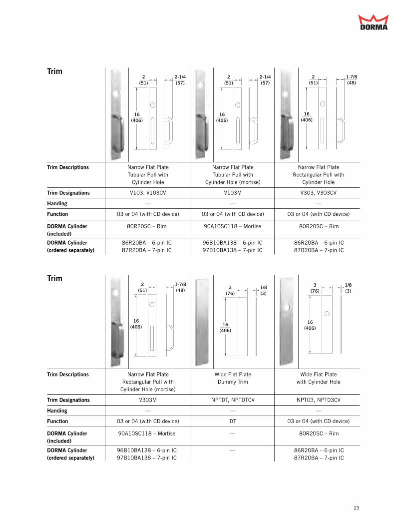
22
Trim
Trim Descriptions Exit Only Narrow Flat Plate Narrow Flat PlateDummy Trim with Cylinder Hole
Trim Designations No Trim VODT, VODTCV VO03, VO03CV
Handing — — —
Function 01 DT 03 or 04 (with CD device)
DORMA Cylinder — — 80R20SC – Rim(included)
DORMA Cylinder — — 86R20BA – 6-pin IC(ordered separately) 87R20BA – 7-pin IC
Trim
Trim Descriptions Narrow Flat Plate Narrow Flat Plate Narrow Flat Platewith Cylinder Hole (mortise) Tubular Pull Rectangular Pull
Trim Designations VO03M V102, V102CV V302, V302CV
Handing — — —
Function 03 or 04 (with CD device) 02 02
DORMA Cylinder 90A10SC118 – Mortise — —(included)
DORMA Cylinder 96B10BA138 – 6-pin IC — —(ordered separately) 97B10BA138 – 7-pin IC
2(51)
1/8(3)
16(406)
16(406)
2(51)
1/8(3)
16(406)
2(51)
1/8(3)
2(51)
2-1/4(57)
16(406)
16(406)
2(51)
1-7/8(48)
23
Trim
Trim Descriptions Narrow Flat Plate Narrow Flat Plate Narrow Flat PlateTubular Pull with Tubular Pull with Rectangular Pull with
Cylinder Hole Cylinder Hole (mortise) Cylinder Hole
Trim Designations V103, V103CV V103M V303, V303CV
Handing — — —
Function 03 or 04 (with CD device) 03 or 04 (with CD device) 03 or 04 (with CD device)
DORMA Cylinder 80R20SC – Rim 90A10SC118 – Mortise 80R20SC – Rim(included)
DORMA Cylinder 86R20BA – 6-pin IC 96B10BA138 – 6-pin IC 86R20BA – 6-pin IC(ordered separately) 87R20BA – 7-pin IC 97B10BA138 – 7-pin IC 87R20BA – 7-pin IC
Trim
Trim Descriptions Narrow Flat Plate Wide Flat Plate Wide Flat PlateRectangular Pull with Dummy Trim with Cylinder HoleCylinder Hole (mortise)
Trim Designations V303M NPTDT, NPTDTCV NPT03, NPT03CV
Handing — — —
Function 03 or 04 (with CD device) DT 03 or 04 (with CD device)
DORMA Cylinder 90A10SC118 – Mortise — 80R20SC – Rim(included)
DORMA Cylinder 96B10BA138 – 6-pin IC — 86R20BA – 6-pin IC(ordered separately) 97B10BA138 – 7-pin IC 87R20BA – 7-pin IC
16(406)
2(51)
2-1/4(57)
16(406)
2(51)
2-1/4(57)
2(51)
16(406)
1-7/8(48)
2(51)
16(406)
1-7/8(48)
3(76)
16(406)
1/8(3)
3(76)
16(406)
1/8(3)

TrimDORMA 9000
24
Trim
Trim Descriptions Wide Flat Plate Wide Flat Plate Wide Flat Platewith Cylinder Hole (mortise) Tubular Pull Rectangular Pull
Trim Designations NPT03M PTT02, PTT02CV PRT02, PRT02CV
Handing — — —
Function 03 or 04 (with CD device) 02 02
DORMA Cylinder 90A10DC118 – Mortise — —(included)
DORMA Cylinder 96B10BA138 – 6-pin IC — —(ordered separately) 97B10BA138 – 7-pin IC
Trim
Trim Descriptions Wide Flat Plate Wide Flat Plate Wide Flat PlateTubular Pull with Tubular Pull with Rectangular Pull
Cylinder Hole Cylinder Hole (mortise) with Cylinder Hole
Trim Designations PTT03, PTT03CV PTT03M PRT03, PRT03CV
Handing — — —
Function 03 or 04 (with CD device) 03 or 04 (with CD device) 03 or 04 (with CD device)
DORMA Cylinder 80R20SC – Rim 90A10SC118 – Mortise 80R20SC – Rim(included)
DORMA Cylinder 86R20BA – 6-pin IC 96B10BA138 – 6-pin IC 86R20BA – 6-pin IC(ordered separately) 87R20BA – 7-pin IC 97B10BA138 – 7-pin IC 87R20BA – 7-pin IC
16(406)
3(76)
2-1/4(57)
16(406)
3(76)
1-7/8(48)
16(406)
3(76)
1-7/8(48)
3(76)
16(406)
1/8(3)
16(406)
3(76)
2-1/4(57)
16(406)
3(76)
2-1/4(57)

25
Trim
Trim Descriptions Wide Flat Plate Wide Flat Plate Wide Flat PlateRectangular Pull with Tubular Pull with Rectangular Pull withCylinder Hole (mortise) Thumbpiece Thumbpiece
Trim Designations PRT03M HTT22, HTT22CV, HTT22M HRT22, HRT22CV, HRT22M
Handing — — —
Function 03 or 04 (with CD device) 22 22
DORMA Cylinder 90A10SC118 – Mortise — —(included)
DORMA Cylinder 96B10BA138 – 6-pin IC — —(ordered separately) 97B10BA138 – 7-pin IC
Trim
Trim Descriptions Wide Flat Plate Wide Flat Plate Raised Escutcheon PlateTubular Pull with Thumbpiece Rectangular Pull with Dummy Trim
and Cylinder Hole Thumbpiece and Cylinder Hole
Trim Designations HTT05, HTT05CV, HTT05M HRT05, HRT05CV, HRT05M YODTHTT06, HTT06CV HRT06, HRT06CV
Handing — — —
Function 05 or 06 (HTT06, HTT06CV) 05 or 06 (HRT06, HRT06CV) DT
DORMA Cylinder 90A10SC118 – Mortise 90A10SC118 – Mortise —(included)
DORMA Cylinder 96A10BA138 – 6-pin IC 96A10BA138 – 6-pin IC —(ordered separately) 97A10BA138 – 7-pin IC 97A10BA138 – 7-pin IC
16(406)
3(76)
2-1/4(57)
16(406)
3(76)
1-7/8(48)
2-3/4(70)
8-1/2(216)
7/8(22)
16(406)
3(76)
1-7/8(48)
16(406)
3(76)
2-1/4(57)
16(406)
3(76)
1-7/8(48)

TrimDORMA 9000
26
Trim
Trim Descriptions Raised Escutcheon Plate Raised Escutcheon Plate Raised Escutcheon Platewith Cylinder Hole with Cylinder Hole (mortise) Knob with Cylinder Hole
(rigid trim)
Trim Designations YO03 YO03M YK03R
Handing — — —
Function 03 or 04 (with CD device) 03 or 04 (with CD device) 03 or 04 (with CD device)
DORMA Cylinder 80R20SC – Rim 90X10SC112 – Mortise 80R20SC – Rim(included)
DORMA Cylinder 86R20BA – 6-pin IC 96D10BA134 – 6-pin IC 86R20BA – 6-pin IC(ordered separately) 87R20BA – 7-pin IC 97D10BA134 – 7-pin IC 87R20BA – 7-pin IC
Trim
Trim Descriptions Raised Escutcheon Plate Raised Escutcheon Plate Raised Escutcheon PlateKnob with Cylinder Hole Rectangular Lever with Rectangular Lever
(mortise × rigid trim) Cylinder Hole (rigid trim) with Cylinder Hole(mortise × rigid trim)
Trim Designation YK03MR YR03R YR03MR
Handing — — —
Function 03 or 04 (with CD device) 03 or 04 (with CD device) 03 or 04 (with CD device)
DORMA Cylinder 90X10SC112 – Mortise 80R20SC – Rim 90X10SC112 – Mortise(included)
DORMA Cylinder 96D10BA134 – 6-pin IC 86R20BA – 6-pin IC 96D10BA134 – 6-pin IC(ordered separately) 97D10BA134 – 7-pin IC 87R20BA – 7-pin IC 97D10BA134 – 7-pin IC
2-3/4(70)
8-1/2(216)
7/8(22)
2-3/4(70)
8-1/2(216)
3-1/2(89)
2-3/4(70)
8-1/2(216)
3-7/16(87)
2-3/4(70)
8-1/2(216)
7/8(22)
2-3/4(70)
8-1/2(216)
3-1/2(89)
2-3/4(70)
8-1/2(216)
3-7/16(87)

27
Trim
Trim Descriptions Raised Escutcheon Plate Raised Escutcheon Plate Raised Escutcheon PlateTubular Lever with Cylinder Hole Tubular Lever with Cylinder Curved Lever with
(rigid trim) Hole (mortise × rigid trim) Cylinder Hole (rigid trim)
Trim Designation YT03R YT03MR YC03R
Handing — — —
Function 03 or 04 (with CD device) 03 or 04 (with CD device) 03 or 04 (with CD device)
DORMA Cylinder 80R20SC – Rim 90X10SC112 – Mortise 80R20SC – Rim(included)
DORMA Cylinder 86R20BA – 6-pin IC 96D10BA134 – 6-pin IC 86R20BA – 6-pin IC(ordered separately) 87R20BA – 7-pin IC 97D10BA134 – 7-pin IC 87R20BA – 7-pin IC
Trim
Trim Descriptions Raised Escutcheon Plate Raised Escutcheon Plate Raised Escutcheon PlateCurved Lever with Cylinder Knob with Cylinder Hole Rectangular Lever withHole (mortise × rigid trim) Cylinder Hole
Trim Designation YC03MR YK08M YR08M, YR08MC
Handing — — Specify Hand YR08MC
Function 03 or 04 (with CD device) 08 08
DORMA Cylinder 90X10SC112 – Mortise 90X10SC112 – Mortise 90X10SC112 – Mortise(included)
DORMA Cylinder 96D10BA134 – 6-pin IC 96D10BA134 – 6-pin IC 96D10BA134 – 6-pin IC(ordered separately) 97D10BA134 – 7-pin IC 97D10BA134 – 7-pin IC 97D10BA134 – 7-pin IC
2-3/4(70)
8-1/2(216)
3-7/16(87)
2-3/4(70)
3-7/16(87)
8-1/2(216)
2-3/4(70)
8-1/2(216)
3-7/16(87)
2-3/4(70)
8-1/2(216)
3-7/16(87)
2-3/4(70)
8-1/2(216)
3-7/16(87)
2-3/4(70)
8-1/2(216)
3-1/2(89)

TrimDORMA 9000
28
Trim
Trim Descriptions Raised Escutcheon Plate Raised Escutcheon Plate Raised Escutcheon PlateTubular Lever with Curved Lever with Knob with Cylinder Hole
Cylinder Hole Cylinder Hole
Trim Designations YT08M, YT08MC YC08M, YC08MC YK08, YK09
Handing Specify Hand YT08MC Specify Hand YC08MC —
Function 08 08 08, 09
DORMA Cylinder 90X10SC112 – Mortise 90X10SC112 – Mortise 90X10SC118 – Mortise(included)
DORMA Cylinder 96D10BA134 – 6-pin IC 96D10BA134 – 6-pin IC 96X10BA138 – 6-pin IC(ordered separately) 97D10BA134 – 7-pin IC 97D10BA134 – 7-pin IC 97X10BA138 – 7-pin IC
Trim
Trim Descriptions Raised Escutcheon Plate Raised Escutcheon Plate Raised Escutcheon PlateRectangular Lever with Tubular Lever with Curved Lever with
Cylinder Hole Cylinder Hole Cylinder Hole
Trim Designations YR08, YR08C, YR08x08*, YT08, YT08C YC08, YC08CYR09, YR09C YT09, YT09C YC09, YC09C
Handing Specify Hand YR08C, Specify Hand YT08C, YT09C Specify Hand YC08C, YC09CYR08x08, YR09C
Function 08, 09 08, 09 08, 09
DORMA Cylinder 90X10SC118 – Mortise 90X10SC118 – Mortise 90X10SC118 – Mortise(included)
DORMA Cylinder 96X10BA138 – 6-pin IC 96X10BA138 – 6-pin IC 96X10BA138 – 6-pin IC(ordered separately) 97X10BA138 – 7-pin IC 97X10BA138 – 7-pin IC 97X10BA138 – 7-pin IC
2-3/4(70)
8-1/2(216)
3-1/2(89)
2-3/4(70)
8-1/2(216)
3-7/16(87)
2-3/4(70)
8-1/2(216)
3-7/16(87)
2-3/4(70)
8-1/2(216)
3-7/16(87) 2-3/4
(70)
8-1/2(216)
3-7/16(87)
2-3/4(70)
8-1/2(216)
3-7/16(87)
*YR08x08 trim requires push-side rim cylinder (ordered separately).
DORMA Cylinder: 80R20SC – Rim86R20BA – 6-pin IC87R20BA – 7-pin IC

29
Trim
Trim Descriptions Raised Escutcheon Plate Knob Raised Escutcheon Plate Raised Escutcheon PlateRectangular Lever Tubular Lever
Trim Designations YK02R, YK23, YK23M YR02R, YR23, YR23M YT02R, YT23, YT23M
Handing — — —
Function 02 or 23 02 or 23 02 or 23
DORMA Cylinder (ordered separately) — — —
Trim
Trim Descriptions Raised Escutcheon Plate Key-in-Knob Key-in-KnobCurved Lever Interchangeable Core
Trim Designations YC02R, YC23, YC23M K03, K08 K03IC, K08IC
Handing — Specify Hand Specify Hand
Function 02 or 23 03 or 08 03 or 08
DORMA Cylinder — Includes DORMA key-in-lever/ Accepts SFIC(included) knob cylinder 7013SC KD
DORMA Cylinder — — 76BAxxx – 6-pin IC(ordered separately) 77BAxxx – 7-pin IC
2-3/4(70)
8-1/2(216)
3-7/16(87)
3-3/8(86)
2-9/16(65)
2-3/4(70)
8-1/2(216)
3-1/2(89)
2-3/4(70)
8-1/2(216)
3-7/16(87)
2-3/4(70)
3-7/16(87)
8-1/2(216)
3-3/8(86)
2-9/16(65)

Trim
Trim Descriptions Knob Key-in-Rectangular Lever Key-in-Rectangular LeverInterchangeable Core
Trim Designations K23 R03, R08 R03IC, R08IC
Handing — Specify Hand Specify Hand
Function 23 03 or 08 03 or 08
DORMA Cylinder — Includes DORMA key-in-lever/ Accepts SFIC(included) knob cylinder 7013SC KD
DORMA Cylinder — — 76BAxxx – 6-pin IC(ordered separately) 77BAxxx – 7-pin IC
TrimDORMA 9000
30
Trim
Trim Descriptions Rectangular Lever Key-in-Curved Lever Key-in-Curved Leverinterchangeable Core
Trim Designations R23 C03, C08 C03IC, C08IC
Handing Specify Hand Specify Hand Specify Hand
Function 23 03 or 08 03 or 08
DORMA Cylinder — Includes DORMA key-in-lever/ Accepts SFIC(included) knob cylinder 7013SC KD
DORMA Cylinder — — 76BAxxx – 6-pin IC(ordered separately) 77BAxxx – 7-pin IC
3-3/8(86)
4-7/8(124)
2-9/16(65)
3-3/8(86)
2-9/16(65)
4-7/8(124)
3-3/8 (86)
2-9/16 (65)
3-3/8(86)
2-9/16(65)
4-7/8(124)
3-3/8(86)
4-7/8(124)
2-9/16(65)
3-3/8(86)
2-9/16(65)
4-7/8(124)

31
Trim
Trim Descriptions Curved Lever Heavy-Duty Offset Pullwith Cylinder Hole
Trim Designations C23 POF03HDA
Handing Specify Hand Specify Hand
Function 23 03
DORMA Cylinder — 80R20SC – Rim(included)
DORMA Cylinder — 86R20BA – 6-pin IC(ordered separately) 87R20BA – 7-pin IC
3-3/8 (86)
2-9/16 (65)
4-7/8(124)
Note: All operating trim furnished free wheeling as standard, except mortise devices.
Trim Options
Clutch Lever Trim –Although mandated to meet ADA requirements, lever handlesare especially subject to vandalism and damage. The clutchoption for lever trim includes an internal slip clutch mecha-nism which allows the lever handle to break away withoutdamage or violating security when excessive force is applied.The lever can be lifted back to horizontal to reset it.
An internal dead stop limits the break away to 55° of lever handlerotation. Specify suffix C to trim designation. Available only on YC,YG, YR, or YT trim. Specify hand.
Rigid Trim –Rigid lever and knob option is available on YC, YG, YK, YR, andYT trim. Specify suffix R to trim designation.
Electrified Trim – Electrified Y style trim with integral locking/unlocking option.Trim can be used with models 9100/F9100, 9300/F9300 and9400/F9400. Available as fail-secure or fail-safe. Specifysuffix LFSC (fail-secure) or LFSF (fail-safe) following trimdesignation. Available for the 09 function only. An integralmicroswitch is available as an option to monitor the status ofthe trim. Electrified trim options must use an ES100 powersupply to prevent permanent damage to the electronics. Twodevices can be powered by an ES100 device.
Electrified option also available with the 9500/F9500 mortisedevice which utilizes an electrified mortise lock design.Specify suffix following exit device designation, i.e. 9500LFSF.Available for all styles of trim with an 08 function. This optionis not field-interchangeable between fail-secure and fail-safe.Electrified mortise locks must use a PS531RF power supply toprevent permanent damage to the electronics. Two devices canbe powered by a PS531RF device,
Key-in-Knob and Key-in-Lever trim are reversible in the field.
11"(279)
1-7/8"(48)
1/2"(13)
7"(178)
2"(51)
1"(25)
1/8"(3)

Cylinder SpecificationsDORMA 9000
32
3/4 – 21/32 (20) – (17)
5/16(8)
––11/32
(9)
Min.
Mortise Cylinder
1-1/8(29)
5/16(8)
11/32(9)–
–
3/4 – 21/32 (20) – (17)
Min.
NOTES:1. Reference specific trim on pages 22–31 for DORMA rim
and mortise cylinder requirements.2. Cylinder illustrations are for mortise cylinder requirements.
Trim K03, K08, R03, R08, C03, C08, G03, and G08 use akey-in-lever/knob cylinder.
DORMA 7013SC KD key-in-lever/knob cylinder includedstandard with trim.
Trim K03IC, K08IC, R03IC, R08IC, C03IC, C08IC, G03IC,and G08IC accepts a small format interchangeable corecylinder.
Order DORMA cylinder:76BA – 6-pin IC77BA – 7-pin IC
Interchangeable Core Cylinder Specifications
Key-in-Lever/Knob Cylinder Specifications
Mortise and Rim Cylinder Specifications
Use DORMA cylinder 90X10SC118.
Cylinder Dogging, Exit Alarm, and Delayed Egress Cylinder Specifications
DORMA CAM #10
DORMA CAM #10

Electrical & AuxiliaryEquipment
DORMA 9000
33
Optional Electric Functions
Electric Latch bolt Retraction – Specify suffix ES. A solenoidconcealed in the touchbar assembly provides instantaneousretraction of the latch bolt to allow access from the secureside of the door. Remote control can be accomplished withswitching devices such as key switches and card readers thatprovide a normally open electrical contact. The solenoid israted for continuous duty, 24 VDC, 14-18 AMP inrush for 200milliseconds, 1 AMP holding current. Requires PS501 powersupply and ES105 power transfer. Not available with C sizedevice or 9500 mortise exit devices.
Monitor Switch – Specify suffix MS. Two micro switches in thetouchbar assembly functioning as form C contacts provide localand/or remote notification of two separate appliances when thetouchbar is depressed. Each switch is rated for .5 AMP @ 28VDC maximum.
Latch Monitor – Specify suffix LM. A microswitch attached tothe device chassis provides local and/or remote notification ofthe exit device rods and without depressing the touchbar. Thesingle-pole, double-throw switch is rated at .50 AMP @ 28VDC maximum.
Latch Monitor with Monitor Switch – Specify suffix LM/MS.A combination of Latch Monitor and Monitor Switch functionsin one device.
Latch Monitor with Monitor Switch and Bypass – Specify suffixLM/MS BP. Same as LM/MS above, but an additional single-pole, double-throw switch is triggered by a mortise cylinder foralarm bypass. Cylinder furnished.
The PS501 Power Supply is capable of powering and controlling (2) 9000 Series Exit Devices with the ES ElectricLatch Bolt Retraction feature. Also has the capability ofpowering (2) additional 9000 Series Exit Devices with an optional card. Specify option ES2 CARD.
NOTE: The PS501 Power Supply must be used along with theES105 power transfer to power the ES Electric LatchBolt Retraction feature.
The DORMA 9000 Series exit devices are available with anintegral battery powered alarm. The 102 decibel alarmcontained in the panic device touchbar and rail assemblyactivates when the touchbar is depressed and soundscontinuously until the device is reset or the battery iscompletely discharged. Alternatively, a factory-furnished optionallows the alarm to sound for four (4) minutes, thenautomatically rearm.
Furnished with and controlled by a lock cylinder and key, theunit allows ten (10) seconds to exit through the door afterarming the alarm, indicated by an intermittently flashing redL.E.D. light in the touchbar. A yellow L.E.D. in the touchbar willflash until manually reset by key to indicate an unauthorized exiteven if the alarm has automatically reset.
The unit is furnished with a 9 volt, industrial-grade batteryconcealed in the end cap assembly for easy replacement. Atamperproof switch will activate the alarm if unauthorizedremoval of the battery is attempted. Option is available for 12 or24 volt direct power wiring.
• Specify prefix BPA to 9000 Series model number for battery alarm device.
• Specify prefix BPAR for 4 minute auto reset battery alarm device.
• Specify prefix DWA for direct hard-wired option.• Size A device fits 48" wide door and can be
cut to fit 39" wide doors.• Size B device fits 36" wide door and can be
cut to fit 33" wide doors.• Size C device fits 30" wide door.
• Input: 120 volts• Input circuit protection: 1 AMP circuit breaker• Output: 24 VDC, 14-18 AMP surge,
2 AMP @ 5 volt continuous, per zone• Output circuit protection: 4 AMP fuse• Enclosure: 8" high × 8" wide × 4" deep
NEMA 1 Type enclosure for indoor use with hinged cover and knock-outs
EMERGENCY EXIT ONLYPUSH TO OPEN ALARM WILL SOUND
Optional Electric Functions
PS501 Power Supply
Battery Alarm Exit Device

MullionsDORMA 9000
34
Removable mullions are used with paired doors where a full-width openingis only occasionally required. Doors are fitted with rim exit devices andnormally function as single doors. Available in 8' or 10' lengths.
• Meets demands of heaviest use areas.• Durable extrusion.• Supplied with wood/machine screws and anchors.
1310 - 8 - 8' mullion1310 - 10 - 10' mullion
WS1310 - 8 - 8' mullion with weatherstripWS1310 - 10 - 10' mullion with weatherstrip
Finish:Aluminum: 628 (Satin).Bronze: 695 (Dark).
• Ideal for high-abuseareas such as schools.
• Meets demands of heaviest use areas.• Heavy-gauge, smooth-surface steel construction.• Attractive tube shape with rounded corners.• Supplied with wood/machine screws and anchors.
1330 - 8 - 8' mullion1330 - 10 - 10' mullion
Finish:Prime: 600.
Bottom Fitting
Top Fitting
Stabilizers(Installed on door)
Top Fitting
Bottom Fitting
Stabilizers(Installed on door)
1-1/2(38)
2-1/2(64)
.120(11 Gage)
Finished FloorFinished Floor
1-5/8(41)
2-5/8(67)
1-1/8(29)
Weatherstrip Slots
Bottom Fitting
Set Screw
Top Fitting
Set Screw
Stabilizers(Installed on door)
Finished Floor2
(51)
.120(11 Gage)
3(76)
• For use with U.L. listed fire exit devices.• Meets demands of heaviest use areas.• Large top and bottom fittings for extra
strength.• Heavy-duty tube with rounded corners.• Standard 8' length.• Supplied with wood/machine screws and
anchors.
F1300 - 8 - 8' fire-rated mullion1300 - 8 - 8' non-fire-rated mullion1300 - 10 - 10' non-fire-rated mullion
Finish:Prime: 600.
F1300 Steel Mullion
1310 Aluminum Mullion 1330 Steel Mullion

35
• Easily removable with key.• Keying is standard 1-1/8" mortise cylinder with
01 (AR) cam.• For use with U.L. listed fire exit devices.• Meets demands of heaviest use areas.• Large top and bottom fittings for extra strength.• Heavy-duty tube with rounded corners.• Standard 8' length.• Supplied with wood/machine screws and anchors.
F1340KR - 8 - 8' fire-rated key removable mullion1340KR - 8 - 8' non-fire-rated key removable mullion1340KR - 10 - 10' non-fire-rated key removable mullion
Finish:Prime: 600.
Optional DORMA SFIC:96D01BA138 – 6-pin IC97D01BA138 – 7-pin IC
Top Fitting
Mortise Cylinder90X01SC118 626(Supplied)
Stabilizers(Installed on door)
Set Screw
Bottom Fitting
2(51)
.120(11 Gage)
3(76)
Unlocked
Locked
Finished Floor
F1340KR Key Removable Steel Mullion HC1300 Steel HC Mullion
• For use with pairs of hurricane-rated rim devices on openings up to 8'0" × 8'0".
• 80 psf design pressure rating positive/negative deflection with HC9300 rim device.
• Tested to Miami-Dade TAS 201, 202, 203.• Large top and bottom fittings for extra strength.• Heavy-duty tube with rounded corners.• Standard 8' length.• Supplied with appropriate screws and anchors.
HC1300 - 8 - Heavy-duty 5/16" wall HC mullion*
Finish:Prime: 600.
*For other HC mullions, consult factory
Top Fitting
Set Screw
Stabilizers(Installed on door)
Set Screw
Bottom Fitting
Mullion Adaptor
2(51)
.312(8)
3(76)
Finished Floor
Note: When using a mullion,refer to exit devicetemplate for minimumstile and vertical refer-ence dimensions.

AccessoriesDORMA 9000
Subject to change without notice 11.08CT 3M USA 07000307
DORMA Mexico, S. de R.L. de C.V.Astrónomos 28, Col. EscandónMéxico, D.F. 11800Del. Miguel HidalgoTelephone: (52+55) 5272-6937Facsimile: (52+55) 5272-6948E-mail: [email protected]
DORMA GroupNorth Americawww.dorma-usa.com
DORMA Architectural HardwareDORMA Drive, Drawer ACReamstown, PA 17567-0411Telephone: (800) 523-8483Facsimile: (800) 274-9724E-mail: [email protected]
DORMA Canada1680 Courtney Park Drive,Unit 13Mississauga, Ontario L5T 1R4Telephone: (800) 387-4938Facsimile: (905) 670-5850E-mail: [email protected]
Non-functioning Exit DevicesThe non-functioning exit device looksexactly like the 9000 Series, but hasno latching mechanism. Units can befurnished in standard A or B width orcut to special size when door width isspecified. Order any applicable trimfor push/pull function. Choose thetype of operation required.
9035 Rigid Touchbar Device –Touchpad is permanently fixed and immobile.
9036 Moveable Touchbar Device – Same as 9035 rigid touchbar device, but touchbar is moveable. Similar to standard 9000 Series device.
9036MS Moveable Touchbar Devicewith Microswitch –Same as 9036, but includes microswitch that can be used tocontrol electromagnetic locks, electric strikes, or other electronicappliances.
Sex NutsThe information below serves as a simple reference whenspecifying DORMA 9000 Series exit devices and trim.
9100/F9100 3 packs 9100/F9100 w/trim 1 pack9300 3 packsF9300 4 packs9300/F9300 w/trim 1 pack9400/F9400 6 packs 9400/F9400 w/trim 4 packs9500/F9500 3 packs9500/F9500 w/trim 1 pack
The dummy bar is designed as acompanion to 9000 Series devices.Units consist of the touchbarassembly only and do not includethe device chassis or chassis cover.Door width must be specified.
9030 Rigid Dummy Bar – Touchbar only. Touchpad is permanently fixed and immobile.
9030MS Dummy Bar with Microswitch –Touchbar is moveable and activates included microswitch. Canbe used to control electromagnetic locks, electric strikes, or otherelectronic appliances.
GK9000 Glass Lite Shim Kit – Contains two 1/8" thick shims. Permits shimming of the exit device maximum 1/4" off door face without affectingU.L. listing. Designed to accommodate glass lite installed indoor. Furnished bright zinc plated. Optional finishes available, consult factory.
The following conversion kits are the same as options detailedelsewhere in this brochure, but in kit form with required com-ponents and installation instructions for field installation/retrofit.
MS Kit – Monitor Switch in Touchbar KitBPA Kit – Battery Powered Exit Alarm KitBPAR Kit – Battery Powered Exit Alarm, 4 Minute Reset KitDWA Kit – Direct Wired Alarm KitCD Kit – Cylinder Dogging Kit (less cylinder)
For applications where tamper-resistant security screws arerequired, specify TX. Note: Special screw bits are required.
Sex Nuts
GK9000 Glass Lite Shim Kit
Conversion Kits
Non-functioning Exit Devices
Dummy Bar
Security Screws