exionlc pda detector - sciex · exionlc™ pda detector operator guide ... the fse will unpack,...
TRANSCRIPT
ExionLC™ PDA Detector
Operator Guide
October 2015RUO-IDV-05-1842-B
This document is provided to customers who have purchased SCIEX equipment to use in the operation of such SCIEXequipment. This document is copyright protected and any reproduction of this document or any part of this document isstrictly prohibited, except as SCIEX may authorize in writing.
Software that may be described in this document is furnished under a license agreement. It is against the law to copy, modify,or distribute the software on any medium, except as specifically allowed in the license agreement. Furthermore, the licenseagreement may prohibit the software from being disassembled, reverse engineered, or decompiled for any purpose. Warrantiesare as stated therein.
Portions of this document may make reference to other manufacturers and/or their products, which may contain parts whosenames are registered as trademarks and/or function as trademarks of their respective owners. Any such use is intended onlyto designate those manufacturers' products as supplied by SCIEX for incorporation into its equipment and does not implyany right and/or license to use or permit others to use such manufacturers' and/or their product names as trademarks.
SCIEX warranties are limited to those express warranties provided at the time of sale or license of its products and are SCIEX’ssole and exclusive representations, warranties, and obligations. SCIEX makes no other warranty of any kind whatsoever,expressed or implied, including without limitation, warranties of merchantability or fitness for a particular purpose, whetherarising from a statute or otherwise in law or from a course of dealing or usage of trade, all of which are expressly disclaimed,and assumes no responsibility or contingent liability, including indirect or consequential damages, for any use by the purchaseror for any adverse circumstances arising therefrom.
For research use only. Not for use in diagnostic procedures.
AB Sciex is doing business as SCIEX.
The trademarks mentioned herein are the property of AB Sciex Pte. Ltd. or their respective owners.
AB SCIEX™ is being used under license.
© 2015 AB SCIEX
AB Sciex Pte. Ltd.Blk 33, #04-06Marsiling Ind Estate Road 3Woodlands Central Indus. Estate.SINGAPORE 739256
Operator GuideExionLC™ PDA DetectorRUO-IDV-05-1842-B2 of 47
Chapter 1 Introduction...............................................................................................................................5Electrical Precautions.........................................................................................................................................................5
AC Mains Supply..........................................................................................................................................................5Protective Earth Conductor..........................................................................................................................................6
Environmental Precautions................................................................................................................................................6Electromagnetic Environment......................................................................................................................................6Decommissioning and Disposal....................................................................................................................................6
Ventilation Precautions......................................................................................................................................................7Chemical Precautions.........................................................................................................................................................7Static Electricity Precautions .............................................................................................................................................7Equipment Use and Modification.......................................................................................................................................8
Chapter 2 Hazard Symbols.........................................................................................................................9Occupational Health and Safety Symbols...........................................................................................................................9Documentation Symbols and Conventions.......................................................................................................................10
Chapter 3 Overview..................................................................................................................................12
Chapter 4 Operating Instructions............................................................................................................17Precautions......................................................................................................................................................................17
Preparation Before Operation....................................................................................................................................17Precautions for Wavelength Calibration and Wavelength Accuracy Check................................................................18Precautions During Operation....................................................................................................................................18
Turn On the Module.........................................................................................................................................................18
Chapter 5 Service and Maintenance Information...................................................................................20Maintenance, Inspections, and Adjustment.....................................................................................................................20
Prior to Inspection and Maintenance.........................................................................................................................20Periodic Inspection and Maintenance List..................................................................................................................21
Clean or Replace the Flow Cell........................................................................................................................................22Remove the Flow Cell................................................................................................................................................22Clean the Flow Cell....................................................................................................................................................23Install the Flow Cell...................................................................................................................................................27
Replace the D2 Lamp.......................................................................................................................................................28Replace the Dust Filter.....................................................................................................................................................31Clean the Module Surfaces..............................................................................................................................................33
Chapter 6 Troubleshooting......................................................................................................................34Corrective Action for Bubbles..........................................................................................................................................39Insulation Tube................................................................................................................................................................39Corrective Action against Leaks from Cell Window.........................................................................................................40
Appendix A Error Messages.....................................................................................................................41
ExionLC™ PDA DetectorOperator Guide3 of 47RUO-IDV-05-1842-B
Contents
Appendix B Status Panel..........................................................................................................................44
Appendix C Consumables and Spares.....................................................................................................46
Revision History........................................................................................................................................47
Operator GuideExionLC™ PDA DetectorRUO-IDV-05-1842-B4 of 47
Contents

This guide describes the basic operation and troubleshooting for the ExionLCTM PDA Detector . Read this guidethoroughly before using the product and operate the product in accordance with the instructions in this guide.
This guide provides safety instructions and precautions to make sure that the user operates the system safely.Follow all Warning and Caution instructions provided in the guide. For more information, refer to the HardwareUser Guide for the ExionLCTM system.
Keep this guide for future reference. Make sure that it is accessible to the operator of the system.
Electrical Precautions
WARNING! Electrical Shock Hazard. Do not remove the covers. Removing the coversmight cause injury or malfunctioning of the system. The covers need not be removedfor routine maintenance, inspection, or adjustment. Contact the SCIEX FSE for repairsthat require the covers to be removed.
For information on system electrical specifications, refer to the Site Planning Guide.
AC Mains SupplyConnect the system to a compatible AC mains supply as instructed in this guide.
WARNING! Electrical Shock Hazard. Use only qualified personnel for the installationof all electrical supplies and fixtures, and make sure that all installations adhere tolocal regulations and safety standards.
WARNING! Electrical Shock Hazard. Make sure that the system can be disconnectedfrom the AC mains supply outlet in an emergency. Do not block the AC mains supplyoutlet.
CAUTION: Potential System Damage. Do not unpack or connect any system components.The FSE will unpack, connect, and configure the system for the proper operating voltage.
ExionLC™ PDA DetectorOperator Guide5 of 47RUO-IDV-05-1842-B
1Introduction
Protective Earth ConductorThe mains supply must include a correctly installed protective earth conductor. The protective earth conductormust be installed or checked by a qualified electrician before the system is connected.
WARNING! Electrical Shock Hazard. Do not intentionally interrupt the protectiveearth conductor. Any interruption of the protective earth conductor will create anelectrical shock hazard.
Environmental PrecautionsUse qualified personnel for the installation of electrical mains, heating, ventilation, and plumbing supplies andfixtures. Make sure that all of the installations comply with local bylaws and biohazard regulations. For moreinformation about the required environmental conditions for the system, refer to the Site Planning Guide.
WARNING! Biohazard. For biohazardous material use, always comply with localregulations for hazard assessment, control, and handling. This system or any part isnot intended to act as a biological containment.
Electromagnetic Environment
CAUTION: Potential Wrong Result. Do not use this device in close proximity to sources ofstrong electromagnetic (EMC) radiation (for example, unshielded intentional RF sources),as EMC radiation might interfere with the proper operation and cause a wrong result.
Make sure that a compatible electromagnetic environment for the equipment can be maintained so that the devicewill perform as intended.
Decommissioning and DisposalBefore decommissioning, decontaminate the system following local regulations.
When removing the system from service, separate and recycle different materials according to national and localenvironmental regulations.
Do not dispose of system components or subassemblies, including computer parts, as unsorted municipal waste.Follow local municapal waste ordinances for proper disposal provisions to reduce the environmental impact ofWEEE (waste, electrical and electronic equipment). To safely dispose of this equipment, contact a local CustomerService office for complimentary equipment pickup and recycling.
Operator GuideExionLC™ PDA DetectorRUO-IDV-05-1842-B6 of 47
Introduction
Note: SCIEX will not accept any system returns without a completed Decontamination Form. Contact an FSEto obtain a copy of the form.
Ventilation PrecautionsThe venting of fumes and disposal of waste must comply with all of the federal, state, provincial, and local healthand safety regulations. It is the customer's responsibility to make sure that the air quality is maintained in compliancewith local health and safety regulations.
Chemical Precautions
• Determine which chemicals have been used in the system prior to service and regular maintenance. Refer toSafety Data Sheets for the health and safety precautions that must be followed with chemicals.
• Work in a well-ventilated area.
• Always wear assigned personal protective equipment, including powder-free neoprene or nitrile gloves, safetyglasses, and a laboratory coat.
• Follow required electrical safe work practices.
• Avoid ignition sources when working with flammable materials, such as isopropanol, methanol, and otherflammable solvents.
• Take care in the use and disposal of any chemicals. Potential risk of personal injury if proper procedures forhandling and disposing of chemicals are not followed.
• Avoid skin contact with chemicals during cleaning and wash hands after use.
• Comply with all of the local regulations for the storage, handling, and disposal of biohazardous, toxic, orradioactive materials.
• (Recommended) Use secondary containment trays beneaththe solvent bottles and the waste collection containerto capture potential chemical spills.
Static Electricity PrecautionsLiquid chromatography (LC) uses flammable organic solvents as the mobile phase. LC systems are also often usedwhere large amount of flammable substances are present. Thus, there is a risk of accidents involving fire orexplosion.
The major cause of these accidents is static electricity. Devising preventative measures for static electricity can bedifficult, because the symptoms before an accident vary and can be hard to detect, because such accidents occur
ExionLC™ PDA DetectorOperator Guide7 of 47RUO-IDV-05-1842-B
Introduction

as a result of several simultaneous incidents. For recommended methods for preventing static electricity accidents,refer to the Hardware User Guide for the ExionLCTM system.
Equipment Use and Modification
WARNING! Electrical Shock Hazard. Do not remove the covers. Removing the coversmight cause injury or malfunctioning of the system. The covers need not be removedfor routine maintenance, inspection, or adjustment. Contact the SCIEX FSE for repairsthat require the covers to be removed.
WARNING! Personal Injury Hazard. Use SCIEX-recommended parts only. Use of partsnot recommended by SCIEX or use of parts for any use other than their intendedpurpose can place the user at risk of harm or negatively impact system performance.
Use the system indoors in a laboratory that complies with the environmental conditions recommended in the SitePlanning Guide.
If the system is used in an environment or in a manner not prescribed by the manufacturer, then the protectionprovided by the equipment might be impaired.
Unauthorized modification or operation of the system might cause personal injury and equipment damage, andmight void the warranty. Erroneous data might be generated if the system is operated either above or below therecommended environmental conditions or operated with unauthorized modifications. Contact an FSE for informationon servicing the system.
Operator GuideExionLC™ PDA DetectorRUO-IDV-05-1842-B8 of 47
Introduction
This section lists the hazard symbols and conventions used in the laboratory environment, on the system, and inthe documentation.
Occupational Health and Safety SymbolsThis section describes some occupational health and safety symbols found in the documentation and laboratoryenvironment.
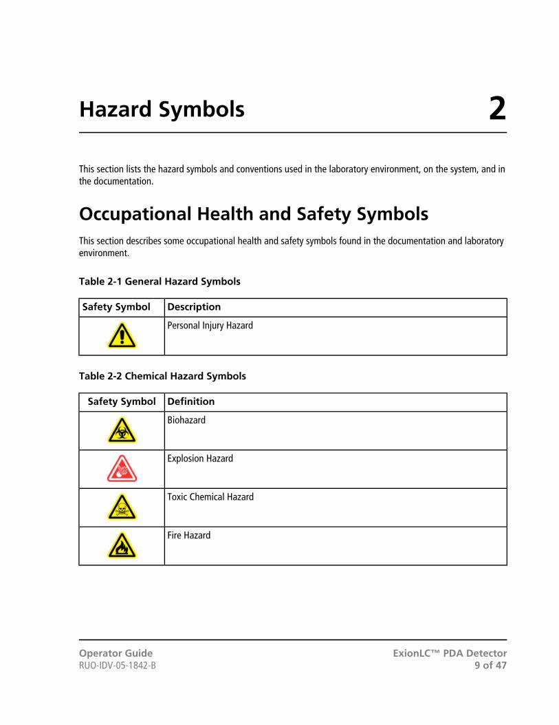
Table 2-1 General Hazard Symbols
DescriptionSafety Symbol
Personal Injury Hazard
Table 2-2 Chemical Hazard Symbols
DefinitionSafety Symbol
Biohazard
Explosion Hazard
Toxic Chemical Hazard
Fire Hazard
ExionLC™ PDA DetectorOperator Guide9 of 47RUO-IDV-05-1842-B
2Hazard Symbols

Table 2-3 Electrical Hazard Warning Symbols
DefinitionSafety Symbol
Electrical Shock Hazard
Table 2-4 Mechanical Hazard Symbols
DefinitionSafety Symbol
Hot Surface Hazard
Table 2-5 Radiation Hazard Symbols
DefinitionSafety Symbol
Laser Radiation Hazard
Documentation Symbols and ConventionsThe following symbols and conventions are used throughout the guide.
DANGER! Danger signifies an action which leads to severe injury or death.
WARNING! Warning signifies an action that could cause personal injury if precautionsare not followed.
CAUTION: Caution signifies an operation that could cause damage to the system orcorruption or loss of data if precautions are not followed.
Note: Note emphasizes significant information in a procedure or description.
Operator GuideExionLC™ PDA DetectorRUO-IDV-05-1842-B10 of 47
Hazard Symbols
Tip! Tip provides useful information that helps apply the techniques and procedures in the text for a specificneed and provides shortcuts, but is not essential to the completion of a procedure.
ExionLC™ PDA DetectorOperator Guide11 of 47RUO-IDV-05-1842-B
Hazard Symbols

The ExionLCTM PDA Detector is a photodiode array (PDA), UV-Vis detector designed for use with an ExionLCTM
ultra high performance liquid chromatograph system (HPLC), and was developed to satisfy demands for greateraccuracy and sensitivity in analysis.
A photodiode array detector continuously monitors spectra over the entire wavelength range. Use of a deuterium(D2) lamp as the light source allows high sensitivity measurement of chromatograms and absorbance spectra overa wavelength range of 190 nm to 700 nm.
• Continuous monitoring of the absorbance spectra of eluted components can improve analysis reliability.
• Identification of components from absorbance spectra
The combined use of retention time with absorbance spectra provides greater accuracy in identification.
• Impurities check
Eluted peaks can be inspected to determine whether they are generated from a single component or mixedwith impurities.
• An improved optical system provides high spectral resolution and excellent S/N performance.
A variable slit is incorporated to enable even higher sensitivity according to the application.
• Polychomator temperature control reduces baseline drift caused by fluctuations in room temperature.
Operator GuideExionLC™ PDA DetectorRUO-IDV-05-1842-B12 of 47
3Overview

Figure 3-1 Front
DescriptionItem
Display. Shows the statuses of lamps and the module.1
Dust filter. Prevents dust from being sucked into the external air inlet, which draws in air to coolthe inside of the module. Refer to Replace the Dust Filter.
2
Front cover. Open this cover to install or perform maintenance on the flow cell.3
Power switch. Turns the power on and off.4
Left-side cover. Open this cover to replace the lamp.5
ExionLC™ PDA DetectorOperator Guide13 of 47RUO-IDV-05-1842-B
Overview
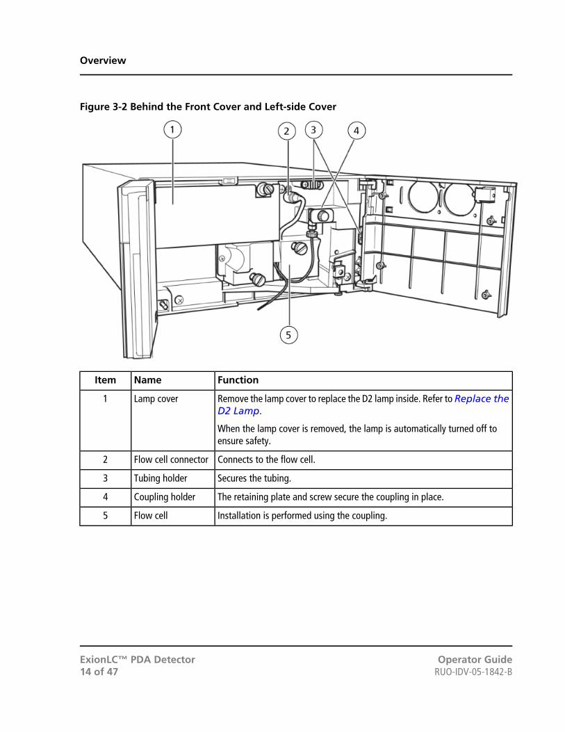
Figure 3-2 Behind the Front Cover and Left-side Cover
FunctionNameItem
Remove the lamp cover to replace the D2 lamp inside. Refer to Replace theD2 Lamp.
When the lamp cover is removed, the lamp is automatically turned off toensure safety.
Lamp cover1
Connects to the flow cell.Flow cell connector2
Secures the tubing.Tubing holder3
The retaining plate and screw secure the coupling in place.Coupling holder4
Installation is performed using the coupling.Flow cell5
Operator GuideExionLC™ PDA DetectorRUO-IDV-05-1842-B14 of 47
Overview
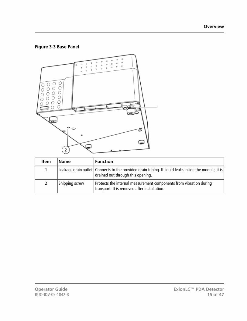
Figure 3-3 Base Panel
FunctionNameItem
Connects to the provided drain tubing. If liquid leaks inside the module, it isdrained out through this opening.
Leakage drain outlet1
Protects the internal measurement components from vibration duringtransport. It is removed after installation.
Shipping screw2
ExionLC™ PDA DetectorOperator Guide15 of 47RUO-IDV-05-1842-B
Overview

Figure 3-4 Back
FunctionNameItem
Used for the interface of control signals and analysis data through the network.ETHERNET connector1
Reserved for use by service personnel.RS-232C connector2
Used for the input and output of analysis start and stop signals, and eventsignals when an error occurs. These are used to connect to external equipment.Refer to the Peripheral Devices Setup Guide for the Analyst® software.
Externalinput/outputterminals
3
Not applicable.INTEGRATORconnectors (fourchannels)
4
Contains the fuses.Fuse holders5
Connector for the power cable.Power cordconnector
6
Fan for internal cooling (keep a minimum of 100 mm between the rear of themodule and the wall.)
Cooling fan7
Used to initialize the module.INITIALIZE button8
Press this button to clear errors.CLEAR button9
Operator GuideExionLC™ PDA DetectorRUO-IDV-05-1842-B16 of 47
Overview

Precautions
Preparation Before Operation
• After starting up the module or turning on the lamp, it takes some time for the baseline to stabilize.
When high sensitivity is required, turn on the lamp in advance while taking into account the time required forbaseline stabilization. As a guide, stabilization takes about 1.5 hours following startup.
• To prevent liquid leakage from the flow cell, tighten the cell window fixing screw on the flow cell every sixmonths.
Refer to Corrective Action against Leaks from Cell Window.
Fittings
Always use the fittings provided with the module. Otherwise, interior parts of the cell might be damaged due tohigh pressure generated within the cell when the cell plumbing is clogged.
Note: Any damage to the cell resulting from the use of fittings other than those provided voids the guarantee.
Refer to:
• Plumbing Between Column and Detector in the Hardware User Guide.
• Remove the Flow Cell
• Install the Flow Cell
Performance Checks
Perform these inspections daily to maintain module performance:
• Flow cell bubble removal and liquid leakage check
Refer to Corrective Action against Leaks from Cell Window.
• Lamp light intensity check
• Wavelength accuracy check
Refer to Service and Maintenance Information.
ExionLC™ PDA DetectorOperator Guide17 of 47RUO-IDV-05-1842-B
4Operating Instructions
Precautions for Wavelength Calibration and WavelengthAccuracy CheckWhen conducting wavelength calibration or a wavelength accuracy check, perform one of the following flow cellpreparation procedures.
• Flush the flow cell with a mobile phase that does not exhibit absorption in the wavelength region above 230nm (such as water, acetonitrile, methanol).
• Fill the flow cell with one of these mobile phases.
Note: The wavelength calibration and wavelength accuracy check include measurement of the lamp lightintensity as standard at the D2 lamp emission line wavelengths (656.1 nm, 486.0 nm) and holmium oxide filterabsorption wavelengths (360.8 nm, 287.6 nm, 241.5 nm). If the flow cell contains air bubbles or residue from alight absorbing sample, wavelength calibration and wavelength accuracy check might not operate properly.
Precautions During Operation• Be sure to close the cover during measurement. Opening the left or front covers during high sensitivity
measurement might cause an increase in baseline fluctuation and noise.
Precautions for Air Conditioner
• When performing high sensitivity measurement, turn on the power to the PDA Detector after the roomtemperature is stabilized.
• Furthermore, when using a room air conditioner, keep it running during analysis to maintain a constant roomtemperature.
Note: The PDA Detector controls the temperature of the optical system to reduce absorbance baseline drift dueto room temperature fluctuation. The detector measures ambient temperature for 15 minutes after the poweris turned on and defines the temperature control level according to the measured temperature. If the roomtemperature is unstable after the power is turned on, the control temperature might be inaccurate and effectsof room temperature change such as baseline drift in sync with temperature fluctuation, might appear duringanalysis. In addition, if the air conditioner is turned off, or if for some other reason the room temperature changestoo much, the temperature control on the optical system might become inadequate.
Turn On the Module
• Press the power switch.
Operator GuideExionLC™ PDA DetectorRUO-IDV-05-1842-B18 of 47
Operating Instructions

Figure 4-1 Power Button
The following events occur:a. The status indicator light is green and the D2 and CONNECT LEDs begin blinking alternately. While this
is occurring, the module performs the motor home position detection and slit initialization operations.
b. The D2 LED blinks more quickly and the light source lamp starts to turn on. The CONNECT LED illuminateswhen the module establishes communications with the system controller and acquisition computer.
c. After the light source lamp is illuminated, the D2 LED stops blinking and illuminates continuously.
Figure 4-2 Display
DescriptionItem
Green1
Orange2
Green blink3
Fast Green blinking4
Green or off5
Note: Whether the D2 lamp is turned on or not is determined by the setting at the time of the last moduleshutdown. If an error occurs, the status indicator turns red.
ExionLC™ PDA DetectorOperator Guide19 of 47RUO-IDV-05-1842-B
Operating Instructions

Regularly clean and maintain the system for optimal performance. Refer to Periodic Inspection and MaintenanceList on page 21.
WARNING! Radiation Hazard, Biohazard, or Toxic Chemical Hazard. Determinewhether mass spectrometer decontamination is required prior to cleaning ormaintenance. The customer must decontaminate the system prior to cleaningor maintenance if radioactive materials, biological agents, or toxic chemicalshave been used with a mass spectrometer.
Maintenance, Inspections, and Adjustment
WARNING! Personal Injury Hazard. Contact the SCIEX representative if productinstallation, adjustment, or relocation is required.
WARNING! Electrical Shock Hazard. Always turn off the power and then unplug theinstrument prior to performing inspection and maintenance. Otherwise, fire, electricshock, or a malfunction might occur.
To maintain the performance of the module system and to obtain accurate measurement data, perform dailyinspection and periodic calibration.
• For daily maintenance and inspection, refer to Precautions.
• For planned maintenance, contact a SCIEX representative.
• For replacement parts, refer to Consumables and Spares.
• Replacement cycles described for periodic replacement parts are estimates. Replacement might be requiredearlier than the described replacement cycles depending on usage environment and frequency.
Prior to Inspection and Maintenance• Purge the mobile phase in the flow lines with water.
• Wipe away any dirt from the front panel and the main cover.
• Wipe away any dirt from the screen with tissue paper or a soft cloth moistened with water.
Operator GuideExionLC™ PDA DetectorRUO-IDV-05-1842-B20 of 47
5Service and MaintenanceInformation

Refer to Clean the Module Surfaces.
Periodic Inspection and Maintenance ListThe replacement and maintenance periods listed in this table are presented only as guidelines. These are notguaranteed periods and will vary depending on the conditions of use.
Remarks2 Years1 YearInspection/Maintenance Item
Item
Replace the filter when it becomesdiscolored from the original white.Refer to Replace the DustFilter.
XDust filter replacement1
Replace the flow cell if it isunclean and light intensity is loweven after cleaning it. Refer toClean or Replace the FlowCell.
XFlow cell replacement2
Replace at about 2000 hours oftotal illumination time. Refer toReplace the D2 Lamp.
XD2 lamp replacement3
Figure 5-1 PDA Detector
ExionLC™ PDA DetectorOperator Guide21 of 47RUO-IDV-05-1842-B
Service and Maintenance Information

After inspection and maintenance, inspect for any leakage during pumping. Refer to Troubleshooting.
Clean or Replace the Flow Cell
Note: If cleaning above still does not improve light intensity, replace the flow cell assembly.
Required Materials
• 1 Flow cell ASSY
Remove the Flow Cell
CAUTION: Potential System Damage. Do NOT disassemble the flow cell. It might getdamaged and become unusable.
1. Turn off the PDA Detector.
2. Open the front cover.
3. Loosen the coupling mounting screw and then remove the coupling.
4. Disconnect the connector.
5. Loosen the two cell mounting screws and then remove the cell.
Figure 5-2 Flow Cell
Operator GuideExionLC™ PDA DetectorRUO-IDV-05-1842-B22 of 47
Service and Maintenance Information

DescriptionItem
Connector1
Coupling fixing screw2
Cell fixing screw3
Clean the Flow CellIf the cell interior becomes dirty, use a syringe to flush the cell with a rinsing solution such as isopropanol to cleanthe cell interior. If the dirt is removed, flush the cell once more with isopropanol or mobile phase.
Note: Use of mobile phases containing amines, such as triethylamine, might contaminate the flow cell andincrease noise. If this happens, use 2% formic acid solution for rinsing solution.
Required Materials
• Syringe, 1ML
• Syringe needle
• Coupling 1.6-0.8C
• Male nuts 0.8MN-PEEK
• Male nuts ETFE
• Distilled or deionized water
Note: If an aqueous solvent (especially a solvent containing buffer salts) is used as the mobile phase, purgethe solvent in the cell with water before flushing with isopropanol. If an organic solvent is mixed with a buffersolution, crystals will form and clog the tubing.
ExionLC™ PDA DetectorOperator Guide23 of 47RUO-IDV-05-1842-B
Service and Maintenance Information

Figure 5-3 Required Materials
DescriptionItem
Cell inlet tubing1
Waste container2
Cell outlet tubing3
Male nut EFTE4
Coupling 1.6-0.8C5
Male nut 0.8MN-PEEK6
Syringe needle7
Operator GuideExionLC™ PDA DetectorRUO-IDV-05-1842-B24 of 47
Service and Maintenance Information
DescriptionItem
Syringe8
Plunger9
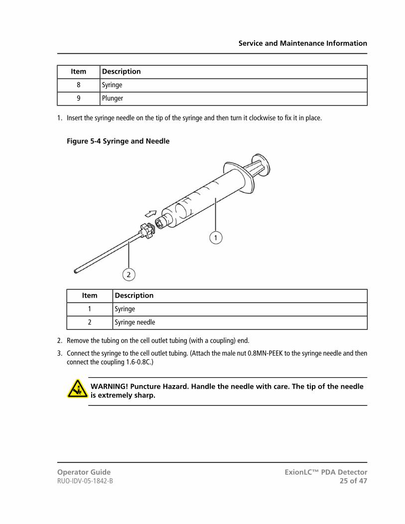
1. Insert the syringe needle on the tip of the syringe and then turn it clockwise to fix it in place.
Figure 5-4 Syringe and Needle
DescriptionItem
Syringe1
Syringe needle2
2. Remove the tubing on the cell outlet tubing (with a coupling) end.
3. Connect the syringe to the cell outlet tubing. (Attach the male nut 0.8MN-PEEK to the syringe needle and thenconnect the coupling 1.6-0.8C.)
WARNING! Puncture Hazard. Handle the needle with care. The tip of the needleis extremely sharp.
ExionLC™ PDA DetectorOperator Guide25 of 47RUO-IDV-05-1842-B
Service and Maintenance Information
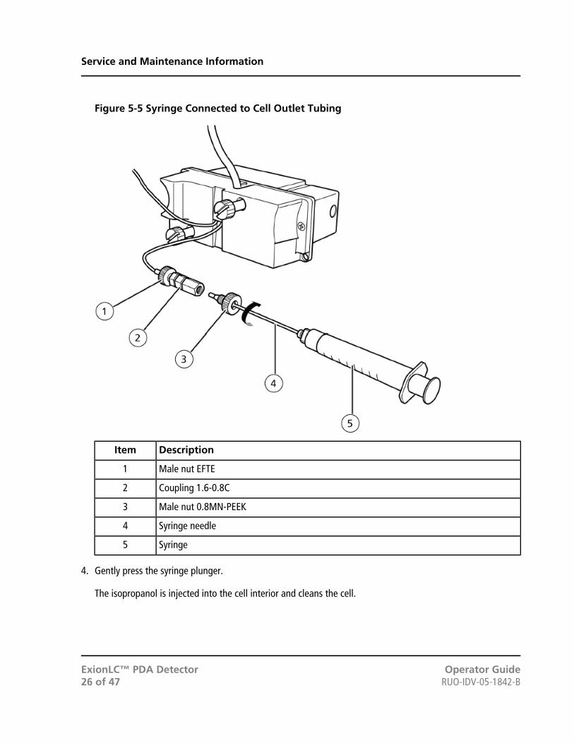
Figure 5-5 Syringe Connected to Cell Outlet Tubing
DescriptionItem
Male nut EFTE1
Coupling 1.6-0.8C2
Male nut 0.8MN-PEEK3
Syringe needle4
Syringe5
4. Gently press the syringe plunger.
The isopropanol is injected into the cell interior and cleans the cell.
Operator GuideExionLC™ PDA DetectorRUO-IDV-05-1842-B26 of 47
Service and Maintenance Information

Figure 5-6 Pressing the Plunger
5. Purge the rinsing solution by using a syringe to flush the flow cell with distilled or deionized water.
6. If cleaning with a syringe does not improve light intensity, replace the column with a coupling, and then pumpa rinsing solution into the flow cell assembly for about two hours.
Install the Flow Cell
1. Orient the flow cell with the connector end upward, align the pin holes in the cell with the positioning pins,install the cell on the pins, and then press the cell flush against the module. Refer to Remove the FlowCell.
2. While placing the flow cell onto the mounting surface, tighten the two cell fixing screws alternately.
3. Insert the connector in the module.
4. Affix the coupling to the module using the coupling mounting screw.
5. Connect the cell inlet tubing to the column and the cell outlet tubing to the waste container.
Note: When performing the above operation, do not let any air enter the flow lines.
6. Reattach the front cover.
ExionLC™ PDA DetectorOperator Guide27 of 47RUO-IDV-05-1842-B
Service and Maintenance Information

Replace the D2 LampA D2 lamp is the light source used in this module. It has a service life of 2000 hours. It is guaranteed for the lesserof 2000 hours or one year of service.
As the D2 lamp used in this module approaches the end of its service life, the light intensity of the lamp beginsto decrease and baseline noise starts to increase. When the lamp approaches the end of its service life, replacethe lamp with a new one.
WARNING! Electrical Shock Hazard. Fire Hazard. Before replacing a lamp, turn thedetector power switch off and unplug the detector. Otherwise, fire, electric shock,or malfunction could result.
WARNING! Radiation Hazard. Do not turn on the power while the lamp housing isexposed to view. You could be exposed to harmful ultraviolet rays.
WARNING! Hot Surface Hazard. Allow the instrument to cool down adequatelybefore performing the lamp replacement procedure. The lamp compartment isextremely hot just after the lamp is turned off.
CAUTION: Potential System Damage:• When holding the lamp, grasp it by the metal flange.
• When the lamp is dirty, wipe it with lens paper soaked in ethanol.
• If the lamp cover is removed when the lamp is on, the lamp is turned off automatically.
• The lamp cannot be turned on while the lamp cover is removed. Be sure to install thelamp cover before turning on the lamp.
• Be careful that the lamp does not break.
• Do not shake the lamp.
Required Materials
• D2 lamp
1. Turn off the module and unplug it from the wall.
2. Open the front cover and left side cover.
3. Loosen the lamp cover mounting screw and then remove the lamp cover.
Operator GuideExionLC™ PDA DetectorRUO-IDV-05-1842-B28 of 47
Service and Maintenance Information

Figure 5-7 Lamp Cover
DescriptionItem
Lamp cover1
Lamp cover fixing screw2
4. Disconnect the connector.
5. Loosen the two D2 lamp mounting screws and then pull the lamp out of the module.
Release the stopper by pinching the part indicated by arrows in the Figure 5-8 on page 30, and then pullout the connector.
ExionLC™ PDA DetectorOperator Guide29 of 47RUO-IDV-05-1842-B
Service and Maintenance Information

Figure 5-8 Removing the Lamp
DescriptionItem
Stopper1
Connector2
D2 Lamp fixing screws3
6. Install the new lamp the same way the old lamp was installed.
While placing the D2 lamp onto the mounting surface, tighten the two lamp fixing screws alternately.
7. Install the lamp cover in its original position on the module.
Install the lamp cover by inserting its edge into the slit in the panel and then secure it by tightening the lampcover mounting screw.
Operator GuideExionLC™ PDA DetectorRUO-IDV-05-1842-B30 of 47
Service and Maintenance Information
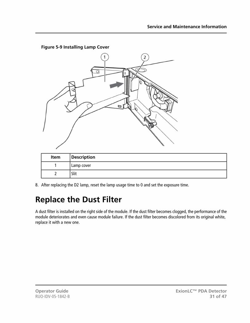
Figure 5-9 Installing Lamp Cover
DescriptionItem
Lamp cover1
Slit2
8. After replacing the D2 lamp, reset the lamp usage time to 0 and set the exposure time.
Replace the Dust FilterA dust filter is installed on the right side of the module. If the dust filter becomes clogged, the performance of themodule deteriorates and even cause module failure. If the dust filter becomes discolored from its original white,replace it with a new one.
ExionLC™ PDA DetectorOperator Guide31 of 47RUO-IDV-05-1842-B
Service and Maintenance Information
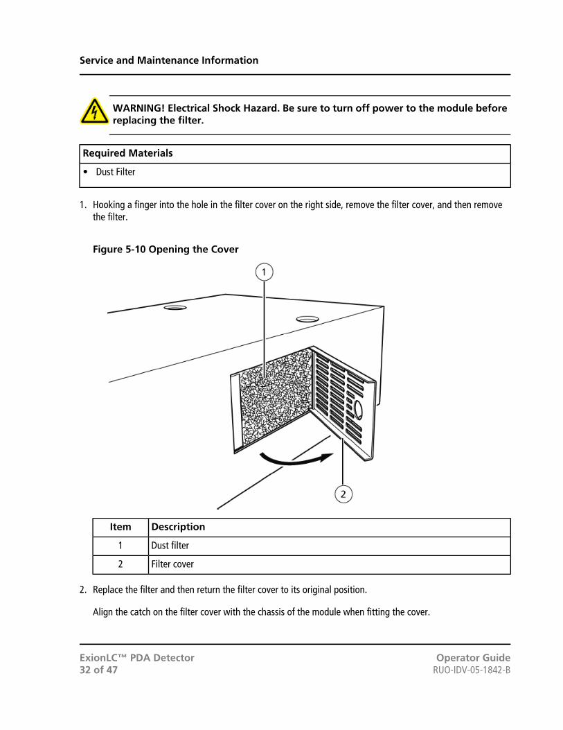
WARNING! Electrical Shock Hazard. Be sure to turn off power to the module beforereplacing the filter.
Required Materials
• Dust Filter
1. Hooking a finger into the hole in the filter cover on the right side, remove the filter cover, and then removethe filter.
Figure 5-10 Opening the Cover
DescriptionItem
Dust filter1
Filter cover2
2. Replace the filter and then return the filter cover to its original position.
Align the catch on the filter cover with the chassis of the module when fitting the cover.
Operator GuideExionLC™ PDA DetectorRUO-IDV-05-1842-B32 of 47
Service and Maintenance Information

Clean the Module Surfaces
Required Materials
• Dry, soft rags, or tissue paper
• For persistent stains
• Diluted, neutral detergent
• Water
1. Wipe the module surfaces with the rag or tissue paper.
2. If the stains persist, follow these steps:
a. Moisten a rag in the diluted, neutral detergent and then wring it dry.
b. Wipe the module surfaces, scrubbing as necessary to remove the stains.
c. Moisten a rag in water and then wring it dry.
d. Wipe the module surfaces.
e. Dry with a dry rag.
CAUTION: Potential System Damage. Do not allow spilled water to remain on theinstrument surface and do not use alcohol or thinner-type solvents to clean the surfaces.Doing so can cause rusting and discoloration.
ExionLC™ PDA DetectorOperator Guide33 of 47RUO-IDV-05-1842-B
Service and Maintenance Information

If a problem cannot be resolved even after taking the corrective action specified in the table, or if a problem is notincluded in the following tables, contact your SCIEX representative.
Table 6-1 Electrical System Issues
Corrective ActionProbable CauseSymptom
Properly connect the power cableplug.
A power cable is unplugged.Power is not on even after the powerswitch is turned on.
Replace the power cable with thesame type of cable.
Internal wires of the power cable arecut.
Use electrical power that meets thespecifications for this module.
The supplied power does not meetspecifications for this module.
Contact an FSE to replace the fuse.The fuse is blown.
Refer to the error code number anderror message and perform theindicated measures. Refer to ErrorMessages.
A transmission error or liquid leakhas occurred.
The error indicator illuminates.
Table 6-2 Baseline Issues
Corrective ActionProbable CauseSymptom
Perform the lamp light intensity test.If the lamp light intensity is low,
Lamp light intensity is insufficient.Excessive noise
perform the corrective action for"Lamp light intensity is low" in thistable.
Contact an FSE.
• Use an appropriate barrier toblock direct exposure of themodule to drafts.
• Move the module to a differentlocation.
A strong draft (for example, from anair conditioner) is being drawn intothe module.
Operator GuideExionLC™ PDA DetectorRUO-IDV-05-1842-B34 of 47
6Troubleshooting

Table 6-2 Baseline Issues (continued)
Corrective ActionProbable CauseSymptom
• Move the module to a sturdycounter.
• Take measures to reduce externalvibrations.
External vibrations are affecting themodule.
• Determine whether the noisedisappears when the LC pump isstopped.
The pump is generating a large pulse.Cyclical spike-like noise occurs.
• Verify the state of the LC pump(pulsation). Eliminate pulsationfrom the pump unit.
• Determine whether the baselineshows a significant change whensolvent delivery is manuallystopped.
• If bubbles are flowing throughthe cell, perform corrective actionfor bubbles. Refer to CorrectiveAction for Bubbles.
The cell contains bubbles.
• Put the tip of the detector draintube in liquid and determinewhether bubbles are exiting thetube.
• If bubbles are flowing throughthe cell, perform corrective actionfor bubbles. Refer to CorrectiveAction for Bubbles.
Bubbles are flowing through cell.Random spike-like noise occurs.
ExionLC™ PDA DetectorOperator Guide35 of 47RUO-IDV-05-1842-B
Troubleshooting
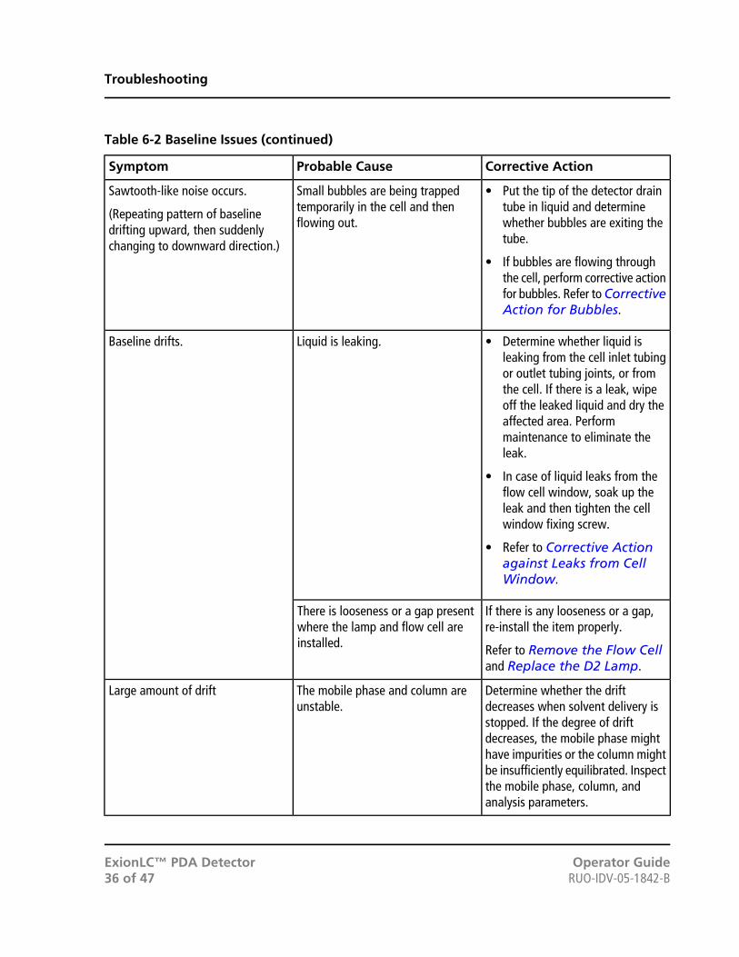
Table 6-2 Baseline Issues (continued)
Corrective ActionProbable CauseSymptom
• Put the tip of the detector draintube in liquid and determinewhether bubbles are exiting thetube.
• If bubbles are flowing throughthe cell, perform corrective actionfor bubbles. Refer to CorrectiveAction for Bubbles.
Small bubbles are being trappedtemporarily in the cell and thenflowing out.
Sawtooth-like noise occurs.
(Repeating pattern of baselinedrifting upward, then suddenlychanging to downward direction.)
• Determine whether liquid isleaking from the cell inlet tubingor outlet tubing joints, or fromthe cell. If there is a leak, wipeoff the leaked liquid and dry theaffected area. Performmaintenance to eliminate theleak.
Liquid is leaking.Baseline drifts.
• In case of liquid leaks from theflow cell window, soak up theleak and then tighten the cellwindow fixing screw.
• Refer to Corrective Actionagainst Leaks from CellWindow.
If there is any looseness or a gap,re-install the item properly.
Refer to Remove the Flow Celland Replace the D2 Lamp.
There is looseness or a gap presentwhere the lamp and flow cell areinstalled.
Determine whether the driftdecreases when solvent delivery is
The mobile phase and column areunstable.
Large amount of drift
stopped. If the degree of driftdecreases, the mobile phase mighthave impurities or the column mightbe insufficiently equilibrated. Inspectthe mobile phase, column, andanalysis parameters.
Operator GuideExionLC™ PDA DetectorRUO-IDV-05-1842-B36 of 47
Troubleshooting

Table 6-2 Baseline Issues (continued)
Corrective ActionProbable CauseSymptom
Module stabilization takes at least 1hour after the lamp is turned on, orin the case of high sensitivitymeasurement, 1.5 hours after thelamp is turned on. Startmeasurement after waiting forstabilization to complete.
Measurement is being performedimmediately after the lamp is turnedon.
• Stabilize the ambienttemperature.
• Install the module in a locationwhere there is little temperaturefluctuation.
• Attach the provided insulationtube to the inlet plumbing. Referto Insulation Tube.
The ambient temperature isfluctuating.
• Determine whether liquid isleaking from the cell inlet tubingor outlet tubing joints, or fromthe cell. If there is a leak, wipeoff the leaked liquid and dry theaffected area. Performmaintenance to eliminate theleak.
• In case of liquid leaks from theflow cell window, soak up theleak and then tighten the cellwindow fixing screw.
• Refer to Corrective Actionagainst Leaks from CellWindow.
Liquid is leaking from the cell.
ExionLC™ PDA DetectorOperator Guide37 of 47RUO-IDV-05-1842-B
Troubleshooting
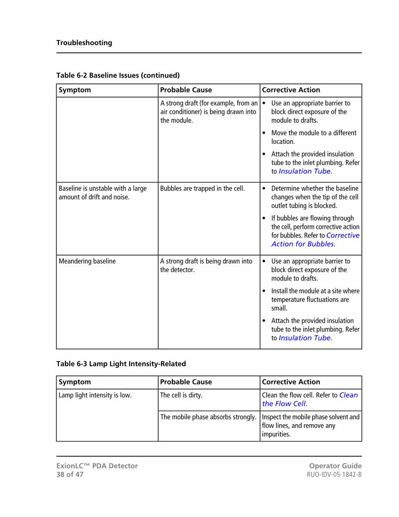
Table 6-2 Baseline Issues (continued)
Corrective ActionProbable CauseSymptom
• Use an appropriate barrier toblock direct exposure of themodule to drafts.
• Move the module to a differentlocation.
• Attach the provided insulationtube to the inlet plumbing. Referto Insulation Tube.
A strong draft (for example, from anair conditioner) is being drawn intothe module.
• Determine whether the baselinechanges when the tip of the celloutlet tubing is blocked.
• If bubbles are flowing throughthe cell, perform corrective actionfor bubbles. Refer to CorrectiveAction for Bubbles.
Bubbles are trapped in the cell.Baseline is unstable with a largeamount of drift and noise.
• Use an appropriate barrier toblock direct exposure of themodule to drafts.
• Install the module at a site wheretemperature fluctuations aresmall.
• Attach the provided insulationtube to the inlet plumbing. Referto Insulation Tube.
A strong draft is being drawn intothe detector.
Meandering baseline
Table 6-3 Lamp Light Intensity-Related
Corrective ActionProbable CauseSymptom
Clean the flow cell. Refer to Cleanthe Flow Cell.
The cell is dirty.Lamp light intensity is low.
Inspect the mobile phase solvent andflow lines, and remove anyimpurities.
The mobile phase absorbs strongly.
Operator GuideExionLC™ PDA DetectorRUO-IDV-05-1842-B38 of 47
Troubleshooting
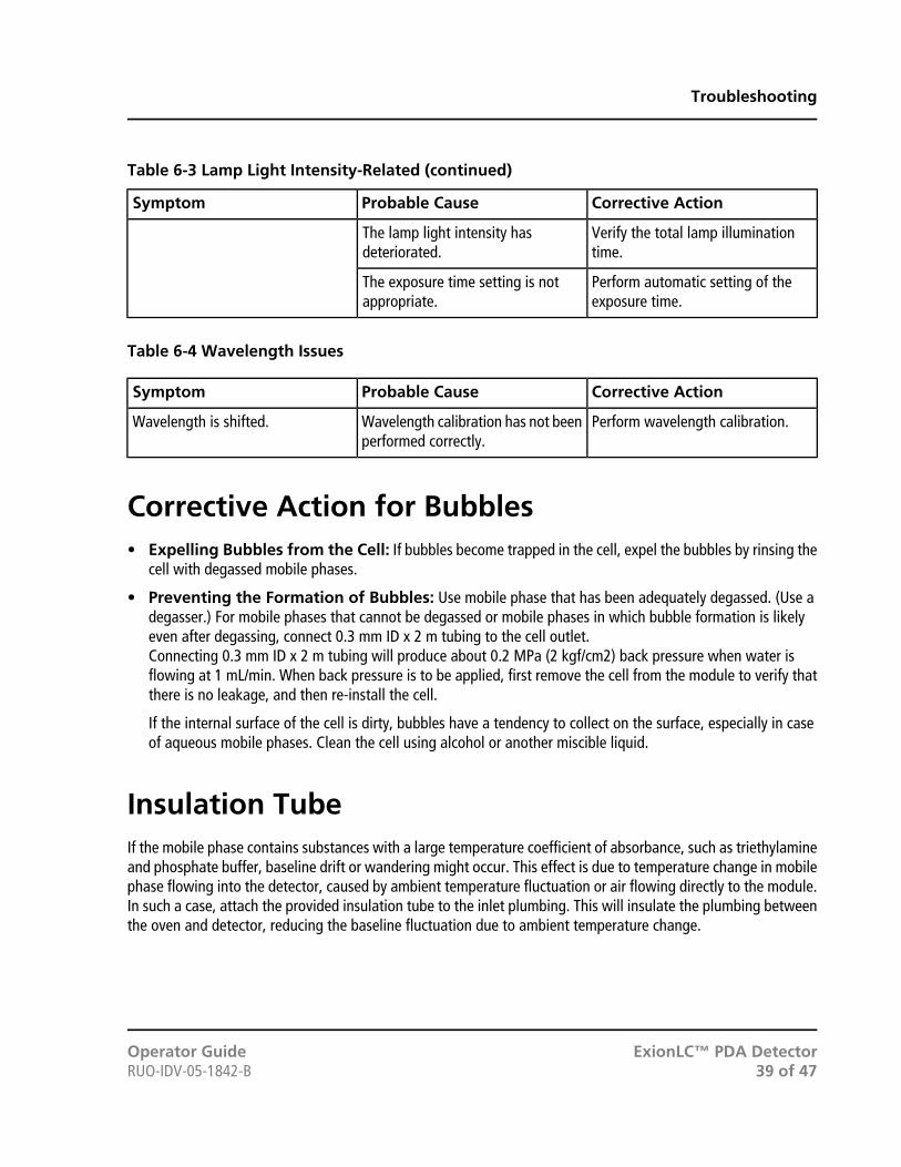
Table 6-3 Lamp Light Intensity-Related (continued)
Corrective ActionProbable CauseSymptom
Verify the total lamp illuminationtime.
The lamp light intensity hasdeteriorated.
Perform automatic setting of theexposure time.
The exposure time setting is notappropriate.
Table 6-4 Wavelength Issues
Corrective ActionProbable CauseSymptom
Perform wavelength calibration.Wavelength calibration has not beenperformed correctly.
Wavelength is shifted.
Corrective Action for Bubbles• Expelling Bubbles from the Cell: If bubbles become trapped in the cell, expel the bubbles by rinsing the
cell with degassed mobile phases.
• Preventing the Formation of Bubbles: Use mobile phase that has been adequately degassed. (Use adegasser.) For mobile phases that cannot be degassed or mobile phases in which bubble formation is likelyeven after degassing, connect 0.3 mm ID x 2 m tubing to the cell outlet.Connecting 0.3 mm ID x 2 m tubing will produce about 0.2 MPa (2 kgf/cm2) back pressure when water isflowing at 1 mL/min. When back pressure is to be applied, first remove the cell from the module to verify thatthere is no leakage, and then re-install the cell.
If the internal surface of the cell is dirty, bubbles have a tendency to collect on the surface, especially in caseof aqueous mobile phases. Clean the cell using alcohol or another miscible liquid.
Insulation TubeIf the mobile phase contains substances with a large temperature coefficient of absorbance, such as triethylamineand phosphate buffer, baseline drift or wandering might occur. This effect is due to temperature change in mobilephase flowing into the detector, caused by ambient temperature fluctuation or air flowing directly to the module.In such a case, attach the provided insulation tube to the inlet plumbing. This will insulate the plumbing betweenthe oven and detector, reducing the baseline fluctuation due to ambient temperature change.
ExionLC™ PDA DetectorOperator Guide39 of 47RUO-IDV-05-1842-B
Troubleshooting
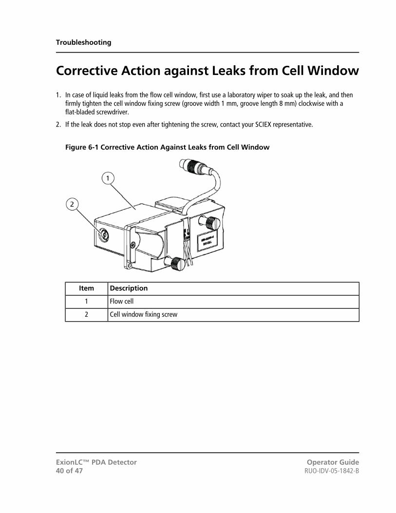
Corrective Action against Leaks from Cell Window
1. In case of liquid leaks from the flow cell window, first use a laboratory wiper to soak up the leak, and thenfirmly tighten the cell window fixing screw (groove width 1 mm, groove length 8 mm) clockwise with aflat-bladed screwdriver.
2. If the leak does not stop even after tightening the screw, contact your SCIEX representative.
Figure 6-1 Corrective Action Against Leaks from Cell Window
DescriptionItem
Flow cell1
Cell window fixing screw2
Operator GuideExionLC™ PDA DetectorRUO-IDV-05-1842-B40 of 47
Troubleshooting
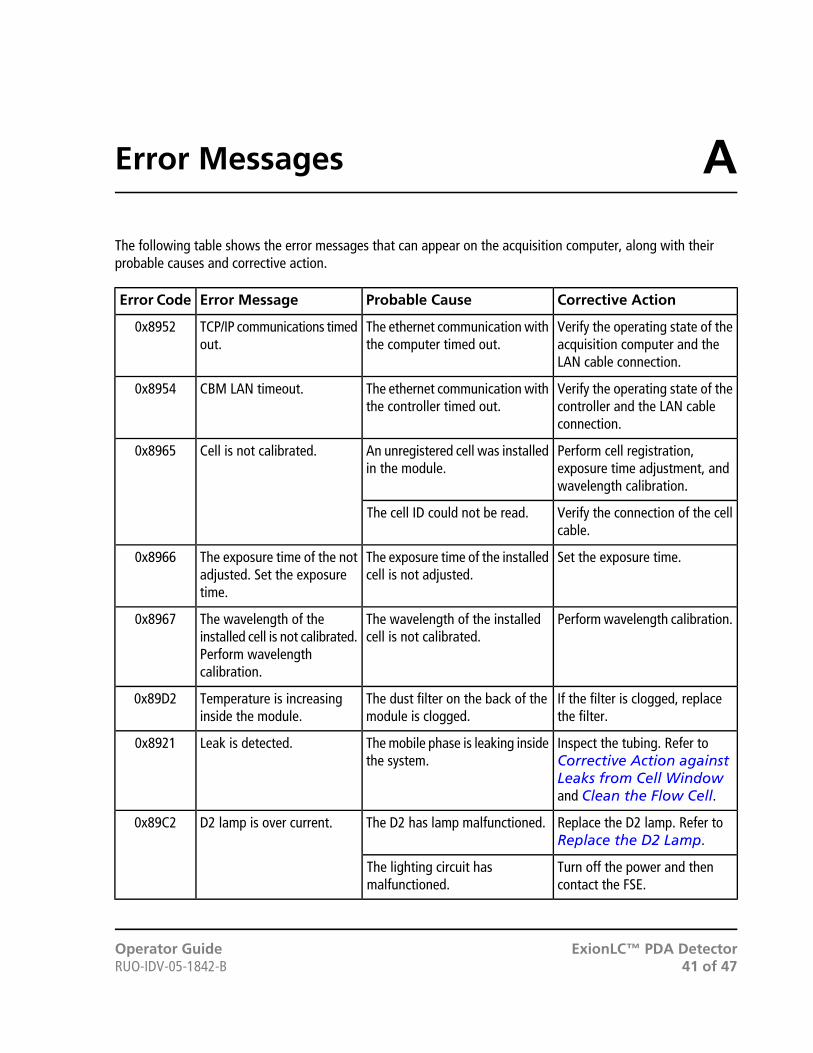
The following table shows the error messages that can appear on the acquisition computer, along with theirprobable causes and corrective action.
Corrective ActionProbable CauseError MessageError Code
Verify the operating state of theacquisition computer and theLAN cable connection.
The ethernet communication withthe computer timed out.
TCP/IP communications timedout.
0x8952
Verify the operating state of thecontroller and the LAN cableconnection.
The ethernet communication withthe controller timed out.
CBM LAN timeout.0x8954
Perform cell registration,exposure time adjustment, andwavelength calibration.
An unregistered cell was installedin the module.
Cell is not calibrated.0x8965
Verify the connection of the cellcable.
The cell ID could not be read.
Set the exposure time.The exposure time of the installedcell is not adjusted.
The exposure time of the notadjusted. Set the exposuretime.
0x8966
Perform wavelength calibration.The wavelength of the installedcell is not calibrated.
The wavelength of theinstalled cell is not calibrated.Perform wavelengthcalibration.
0x8967
If the filter is clogged, replacethe filter.
The dust filter on the back of themodule is clogged.
Temperature is increasinginside the module.
0x89D2
Inspect the tubing. Refer toCorrective Action againstLeaks from Cell Windowand Clean the Flow Cell.
The mobile phase is leaking insidethe system.
Leak is detected.0x8921
Replace the D2 lamp. Refer toReplace the D2 Lamp.
The D2 has lamp malfunctioned.D2 lamp is over current.0x89C2
Turn off the power and thencontact the FSE.
The lighting circuit hasmalfunctioned.
ExionLC™ PDA DetectorOperator Guide41 of 47RUO-IDV-05-1842-B
AError Messages

Corrective ActionProbable CauseError MessageError Code
Replace the D2 lamp. Refer toReplace the D2 Lamp.
The D2 has lamp malfunctioned.There is a problem with theD2 lamp.Inspect the lamp connectionsand the lamp for defects.
0x89C3
Turn off the power and thencontact the FSE.
Lighting circuit malfunction
Turn off the power and thencontact the FSE.
Lighting circuit malfunctionD2 lamp heater is overcurrent.
0x89C7
Replace the D2 lamp. Refer toReplace the D2 Lamp.
The D2 has lamp malfunctioned.D2 lamp heater current islow.
0x89CA
Turn off the power and thencontact the FSE.
Lighting circuit malfunction
If the filter is clogged, replacethe filter. Refer to Replace theDust Filter.
The dust filter on the back of themodule is clogged.
Lamp housing is overheated.0x89C8
Turn off the power and thencontact the FSE.
Lamp compartment fanmalfunction
Lamp housing fan rotationerror.
0x89D6
Turn off the power and thencontact the FSE.
Power heat exhaust fanmalfunction
Power heat exhaust fanrotation error.
0x89D7
Turn off the power and thencontact the FSE.
A malfunction has occurred insidethe module.
Polychromator is overheated.0x89D8
Turn off the power and thencontact the FSE.
A malfunction has occurred insidethe module.
Heater sensor is open.0x89D9
Turn off the power and thencontact the FSE.
A malfunction has occurred insidethe module.
Room sensor is open.0x89DA
Turn off the power and thencontact the FSE.
EEPROM malfunction occurredinside the module.
Invalid EEPROM parameter.0x8904
Verify the connection to thecomputer (network and so on).
Failed to send detector data to theacquisition computer, or thecomputer stopped during analysis.
Communications to PC databuffer overflow.
0x8941
Verify the connection to thecomputer (network and so on).
Failed to send detector data to theacquisition computer, or thecomputer stopped during analysis.
Buffer memory overflow indetector during analysis. It isnot possible to send the dataagain.
0x8944
Perform exposure timeoptimization using SPDM30AUtility.
The signal is saturated becausethe exposure time for the PDAelements is inappropriate.
Photo diode is saturated.0x8945
Operator GuideExionLC™ PDA DetectorRUO-IDV-05-1842-B42 of 47
Error Messages

Corrective ActionProbable CauseError MessageError Code
Turn off the power and thencontact the FSE.
A malfunction has occurred insidethe module.
Lamp housing temperaturesensor is open.
0x897A
Turn off the power and thencontact the FSE.
A malfunction has occurred insidethe module.
Leak sensor is short-circuited.0x8978
Turn off the power and thencontact the FSE.
A malfunction has occurred insidethe module.
Leak sensor is open.0x8979
Change the IP address of themodule or device to resolve thecollision.
A device with the same IP addressas the module exists on the samenetwork.
IP resource contention.0x8956
Install the cell and connect thecable correctly. Refer to Installthe Flow Cell.
The cell is not installed or the cellcable is not connected.
Failed to detect Cell.0x8964
Close the lamp cover. Refer toReplace the D2 Lamp.
The lamp compartment cover wasopened during D2 lampillumination. The lamp has beenturned off to prevent electricshocks and exposure to ultravioletlight.
The light sourcecompartment cover is open.Close the cover.
0x89C6
Install the D2 lamp. Refer toReplace the D2 Lamp.
The D2 lamp is not installed.Failure to detect D2 lamp.0x89CB
Turn off the power and thencontact the FSE.
A malfunction has occurred insidethe module.
Failure to detect lightshutter/filter origin.
0x89D1
If the filter is clogged, replacethe filter.
The dust filter on the back of themodule is clogged.
Abnormal high temperatureis detected inside themodule.
0x89D3
Turn off the power and thencontact the FSE.
A malfunction has occurred insidethe module.
Replace the D2 lamp. Refer toReplace the D2 Lamp.
The D2 has lamp malfunctioned.D2 lamp overvoltage.0x89D4
Turn off the power and thencontact the FSE.
A malfunction has occurred insidethe module.
Replace the D2 lamp. Refer toReplace the D2 Lamp.
The D2 has lamp malfunctioned.D2 lamp overvoltage.0x89D5
Turn off the power and thencontact the FSE.
A malfunction has occurred insidethe module.
ExionLC™ PDA DetectorOperator Guide43 of 47RUO-IDV-05-1842-B
Error Messages
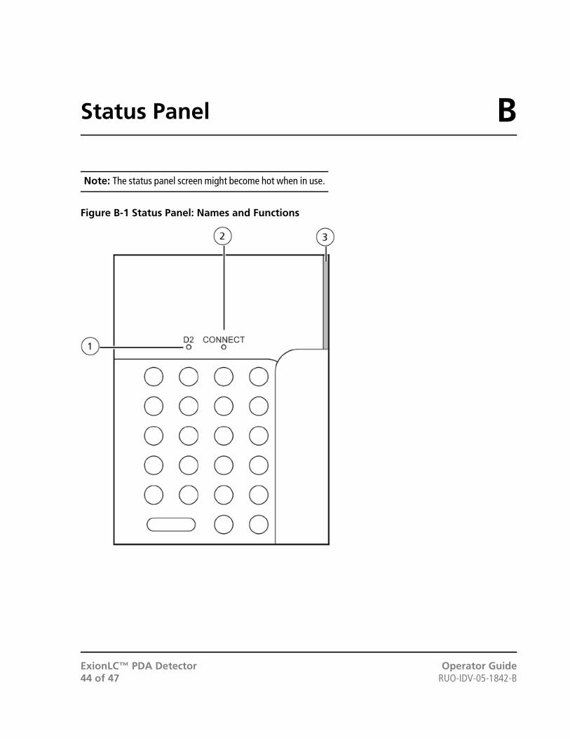
Note: The status panel screen might become hot when in use.
Figure B-1 Status Panel: Names and Functions
Operator GuideExionLC™ PDA DetectorRUO-IDV-05-1842-B44 of 47
BStatus Panel
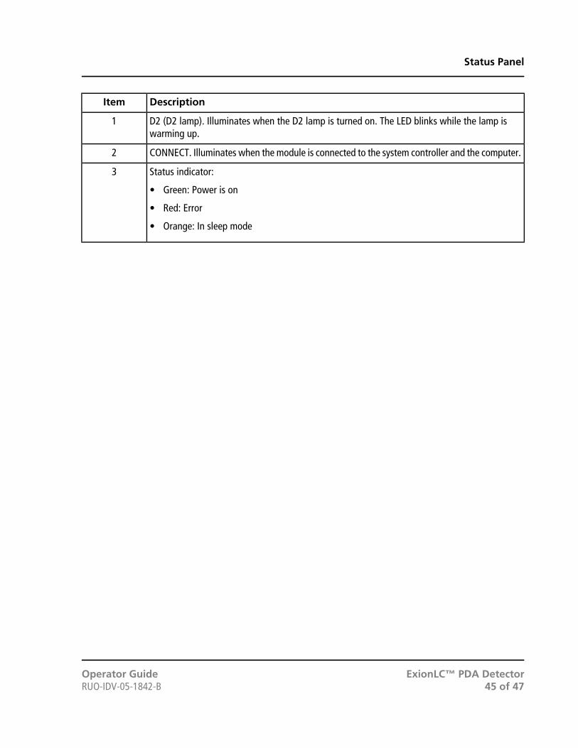
DescriptionItem
D2 (D2 lamp). Illuminates when the D2 lamp is turned on. The LED blinks while the lamp iswarming up.
1
CONNECT. Illuminates when the module is connected to the system controller and the computer.2
Status indicator:
• Green: Power is on
• Red: Error
• Orange: In sleep mode
3
ExionLC™ PDA DetectorOperator Guide45 of 47RUO-IDV-05-1842-B
Status Panel

FeaturesPart No.Option
228-54515D2 (deuterium) lamp
228-54534Dust filter
S228-5675Male nuts ETFE
S228-56760Insulation tube
S086-10504-18Flat-bladed screwdriver
Operator GuideExionLC™ PDA DetectorRUO-IDV-05-1842-B46 of 47
CConsumables and Spares

DateDescriptionRevision
April 2015First release of document.A
October 2015Remove incorrect graphics from Troubleshooting section.B
ExionLC™ PDA DetectorOperator Guide47 of 47RUO-IDV-05-1842-B
Revision History