exhibit a - ct.gov · atitude: l 41.73308000 ongitude: ... # 2 0 # 33 # 87 # 9 # 35 # 6 # 8 # 12 #...
TRANSCRIPT
Northeast Site Solutions Denise Sabo 199 Brickyard Rd Farmington, CT 06032 860-209-4690 [email protected]
October 5, 2017
Members of the Siting Council Connecticut Siting Council Ten Franklin Square New Britain, CT 06051
RE: Tower Share Application
87 MONCE ROAD, BURLINGTON, CT 06013 Latitude: 41.73308000
Longitude: -72.90730000 T-Mobile Site#: CTHA560B-MWAAV
Dear Ms. Bachman:
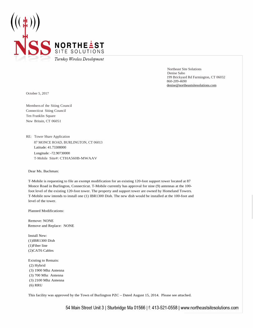
T-Mobile is requesting to file an exempt modification for an existing 120-foot support tower located at 87 Monce Road in Burlington, Connecticut. T-Mobile currently has approval for nine (9) antennas at the 100-foot level of the existing 120-foot tower. The property and support tower are owned by Homeland Towers. T-Mobile now intends to install one (1) IBR1300 Dish. The new dish would be installed at the 100-foot and level of the tower.
Planned Modifications:
Remove: NONE Remove and Replace: NONE
Install New: (1)IBR1300 Dish (1)Fiber line (2)CAT6 Cables
Existing to Remain: (2) Hybrid (3) 1900 Mhz Antenna (3) 700 Mhz Antenna (3) 2100 Mhz Antenna (6) RRU
This facility was approved by the Town of Burlington PZC – Dated August 15, 2014. Please see attached.
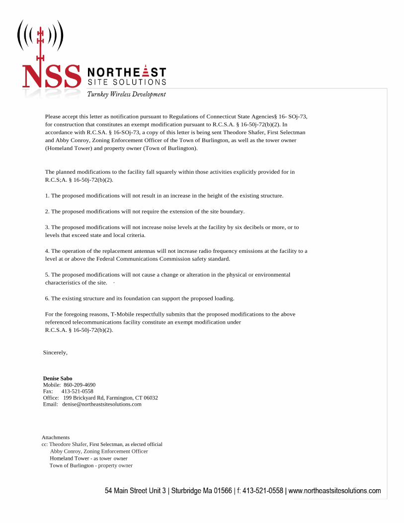
Please accept this letter as notification pursuant to Regulations of Connecticut State Agencies§ 16- SOj-73, for construction that constitutes an exempt modification pursuant to R.C.S.A. § 16-50j-72(b)(2). In accordance with R.C.SA. § 16-SOj-73, a copy of this letter is being sent Theodore Shafer, First Selectman and Abby Conroy, Zoning Enforcement Officer of the Town of Burlington, as well as the tower owner (Homeland Tower) and property owner (Town of Burlington).
The planned modifications to the facility fall squarely within those activities explicitly provided for in R.C.S;A. § 16-50j-72(b)(2).
1. The proposed modifications will not result in an increase in the height of the existing structure.
2. The proposed modifications will not require the extension of the site boundary.
3. The proposed modifications will not increase noise levels at the facility by six decibels or more, or tolevels that exceed state and local criteria.
4. The operation of the replacement antennas will not increase radio frequency emissions at the facility to alevel at or above the Federal Communications Commission safety standard.
5. The proposed modifications will not cause a change or alteration in the physical or environmentalcharacteristics of the site. ·
6. The existing structure and its foundation can support the proposed loading.
For the foregoing reasons, T-Mobile respectfully submits that the proposed modifications to the above referenced telecommunications facility constitute an exempt modification under R.C.S.A. § 16-50j-72(b)(2).
Sincerely,
Denise Sabo Mobile: 860-209-4690 Fax: 413-521-0558 Office: 199 Brickyard Rd, Farmington, CT 06032 Email: [email protected]
Attachments cc: Theodore Shafer, First Selectman, as elected official
Abby Conroy, Zoning Enforcement Officer Homeland Tower - as tower owner
Town of Burlington - property owner

Exhibit A

Kitchen Style
Land Use
Land Class
Mailing Address
Owner
Property Location
Zoning Code
Census Tract
Co-Owner
4101
Neighborhood
Utilities
Acreage
Lot Setting/Desc
Additional Info
Photo
Building Style
Total Rooms
Bedrooms
Half Bathrooms
Building Condition
Primary Construction Details
Account
Property Information
Report Created On
Year Built
Roof Style
Roof Cover
Sketch
Exterior Walls
Interior Walls
Floors
Heating Type
Heating Fuel
Total Living Area
Gross Bldg Area
Map Block Lot
Building Use
Full Bathrooms
Bath Style
Stories
AC Type
Property Listing Report
Town of Burlington, CT
Municipal Mdl-00Municipal Mdl-00
EE
87 MONCE RD87 MONCE RD
R44R44
87 MONCE RD87 MONCE RD
BURLINGTONBURLINGTON CTCT 0601306013
90309030
BURLINGTON TOWN OFBURLINGTON TOWN OF
40004000
RuralRural LevelLevel
Well,SepticWell,Septic
0.80.8
000394000003940011-06-3311-06-33
9/11/2017

Sales HistorySale Date Sale PriceBook/ Page
Valuation Summary
Land
Buildings
Outbuildings
Appraised Assessed
(Assessed value = 70% of Appraised Value)
Improvements
Extras
Total
Owner of Record
Report Created On
Item
Sub Areas
Subarea Type Gross Area (sq ft) Living Area (sq ft)
Total Area
Outbuilding and Extra Items
Type Description
AccountMap Block LotProperty Listing Report
Town of Burlington, CT
4/6/2015
127000 88900
0 0
5500 3850
0
5500 3850
0
132500 92750
50002/1/1995
0
9/11/2017
BURLINGTON TOWN OF
BURLINGTON VOLUNTEER FIRE DEPT
BURLINGTON VOLUNTEER FIRE
335/ 780
00151/0044
00047/0037
Paving-Asphalt
Light w/Pole
Paving-Asphalt
Light w/Pole
3600.00 S.F.
1.00 UNITS
3600.00 S.F.
1.00 UNITS
0
000394000003940011-06-3311-06-33

0.43 AC
0.47 AC
0.23 AC
0.31AC
0.71 AC
0.22 AC
0.22 AC0.28 AC
0.8 AC
0.46 AC0.34 AC
0.24 AC 0.33 AC
0.45 AC 0.36 AC0.34 AC
0.29 Ac
#86
# 106
# 102# 23
# 98
# 29
# 2# 33# 90
# 87
# 9 # 35
# 6 # 8 # 12
# 72 # 45# 15# 11
132'
530.55'
177.74'178.57' 62.43'
109.8'
185.56'
419.76'
92.54'
52.59' 178.76'100'
100'
100'41' 80.53'
19.47'
32.26'
129.49'
18.24'
101.78'
106.68'
37.32'125.21'
50'
134'
176.74'39.8'
5.61'
50' 100'
19-1
26
25
24
23
22
201933
16 21
23 5
6
24-1
20-2
4-1
9-18-1
Monce Rd
Oak St
Woodside St
Disclaimer: This map is for informational purposes only All information is subject to verification by any user. The Town of Burlington and its mapping
contractors assume no legal responsibility for the information contained herein.
Map Produced: July 20170 50 100 150 200Feet
1 inch = 100 feet
µ
Map-Block-Lot
Town of Burlington, Connecticut. Assessment Parcel Map
Address:11-06-33 87 MONCE RD

Exhibit B


Exhibit C

420 MAIN STREET, BLDG 4STURBRIDGE, MA 01566
203-275-6669
462 WALNUT STREETNEWTON, MA 02460
617-212-3123
THIS DOCUMENT IS THE DESIGN PROPERTY ANDCOPYRIGHT OF FORESITE, LLC. AND FOR THE
EXCLUSIVE USE BY THE TITLE CLIENT.DUPLICATION OR USE WITHOUT THE EXPRESS
WRITTEN CONSENTOF THE CREATOR IS STRICTLY PROHIBITED.
DRAWING SCALES ARE INTENDED FOR 11"x17" SIZEPRINTED MEDIA ONLY. ALL OTHER PRINTED SIZES
ARE DEEMED "NOT TO SCALE".
SITE NUMBER: CTHA560BSITE NAME: CTHA560B
SITE ADDRESS: 87 MONCE RDBURLINGTON, CT 06013
SHEET TITLE:
REV DESCRIPTION DATE
A PRELIMINARY 09/14/17
PROJECT MANGER
CONSULTANT:
APPLICANT:
T-MOBILE NORTHEAST LLC35 GRIFFIN ROAD SOUTHBLOOMFIELD, CT 06002
860-692-7100
Cop
yrig
ht ©
201
6 Fo
resi
te L
LC a
ll rig
hts
rese
rved
. The
det
ails
, tem
plat
es, d
raw
ing
form
ats
or a
ny p
ortio
n of
this
doc
umen
t gen
erat
ed b
y Fo
resi
te L
LC m
ay n
ot b
e du
plic
ated
, tra
ced
or u
sed
othe
rwis
e fo
r any
pro
fit-d
riven
ent
erpr
ise.
PROFESSIONAL SEALPROJECT NOTES:
PROJECT SCOPE:
ADDING A BACKHAUL RADIO TO T-MOBILE SECTOR ON THE TOWERWITH ASSOCIATED CABLES.
ADDRESS:
STRUCTURE TYPE:
ZONING DISTRICT:COORDINATES: STRUCTURE HEIGHT:
POWER PROVIDER:
TELCO PROVIDER:
CALL BEFORE YOU DIG:
STRUCTURE OWNER:
PROJECT INFORMATION:
PROJECT TEAM:
SHEET INDEX:T-1: TITLE SHEETLE-1: PLANLE-2: ELEVATION AND DETAILS
APPLICABLE STATE ADOPTION CODES:2016 CONNECTICUT STATE BUILDING CODE (CSBC).
ANSI/TIA-222-G-2005 STRUCTURAL STANDARD FOR ANTENNASUPPORTING STRUCTURES AND ANTENNAS.
2014 NATIONAL ELECTRICAL CODE (NFPA 70) FOR POWER ANDGROUNDING REQUIREMENTS.
T-MOBILE NORTHEAST LLC
APPLICANT:
TOWN OF BURLINGTON200 SPIELMAN ROADBURLINGTON, CT 06013
PROJECT MANGER:
CONSULTANTS:
LANDLORD:
SITE NUMBER: CTHA560BSITE NAME: CTHA560B
SITE ADDRESS: 87 MONCE RD, BURLINGTON, CT 06013 (797DB2 CONFIGURATION)
87 MONCE RDBURLINGTON, CT 06013
FUTURE MONOPOLE BYHOMELAND TOWERS LLC
R-44N 41°44'20.89" & W 72°54'28.08"140' AGL
EVERSOURCE107 SELDEN STREETBERLIN, CT 06037
LIGHT TOWER260 FRANKLIN STREETBOSTON, MA 02110
800-922-4455
HOMELAND TOWERS, LLC (CT011)9 HARMONY ST 2ND FLOORDANBURY, CT 06810203-297-6345
T-MOBILE NORTHEAST, LLC.35 GRIFFIN ROAD SOUTHBLOOMFIELD, CT 06002860-692-7100
NORTHEAST SITE SOLUTIONS420 MAIN STREET, BLDG 4STURBRIDGE, MA 01566MATTHEW [email protected]
FORESITE LLC462 WALNUT STNEWTON, MA 02460SAEED [email protected]
ANTENNA UPGRADESBY
SITE IMAGE:
ZONING / VICINITY MAP:
T-1: TITLE SHEET
1. THIS IS AN UNMANNED TELECOMMUNICATION FACILITY ANDNOT FOR HUMAN HABITATION:
HANDICAPPED ACCESS IS NOT REQUIRED. POTABLE WATER OR SANITARY SERVICE IS NOT REQUIRED.
NO OUTDOOR STORAGE OR ANY SOLID WASTE RECEPTACLES REQUIRED.
2. CONTRACTOR SHALL VERIFY ALL PLANS, EXISTINGDIMENSIONS, AND CONDITIONS ON THE JOB SITE.CONTRACTOR SHALL IMMEDIATELY NOTIFY THEARCHITECT/ENGINEER IN WRITING OF ANY DISCREPANCIESBEFORE PROCEEDING WITH THE WORK. FAILURE TONOTIFY THE ARCHITECT/ENGINEER PLACES THERESPONSIBILITY ON THE CONTRACTOR TO CORRECT THEDISCREPANCIES AT THE CONTRACTOR'S EXPENSE.
3. DEVELOPMENT AND USE OF THE SITE WILL CONFORM TO ALLAPPLICABLE CODES, ORDINANCES AND SPECIFICATIONS.
SITE LOCATION
FSA CM
RF ENGINEER
FOPS
T-MOBILE ENGINEERING AND DEVELOPMENT
APPROVALS:
DATE
DATE
DATE
DATE
DATE
DATE
SITE LOCATION
LEASE EXHIBIT
420 MAIN STREET, BLDG 4STURBRIDGE, MA 01566
203-275-6669
462 WALNUT STREETNEWTON, MA 02460
617-212-3123
THIS DOCUMENT IS THE DESIGN PROPERTY ANDCOPYRIGHT OF FORESITE, LLC. AND FOR THE
EXCLUSIVE USE BY THE TITLE CLIENT.DUPLICATION OR USE WITHOUT THE EXPRESS
WRITTEN CONSENTOF THE CREATOR IS STRICTLY PROHIBITED.
DRAWING SCALES ARE INTENDED FOR 11"x17" SIZEPRINTED MEDIA ONLY. ALL OTHER PRINTED SIZES
ARE DEEMED "NOT TO SCALE".
SITE NUMBER: CTHA560BSITE NAME: CTHA560B
SITE ADDRESS: 87 MONCE RDBURLINGTON, CT 06013
SHEET TITLE:
REV DESCRIPTION DATE
A PRELIMINARY 09/14/17
PROJECT MANGER
CONSULTANT:
APPLICANT:
T-MOBILE NORTHEAST LLC35 GRIFFIN ROAD SOUTHBLOOMFIELD, CT 06002
860-692-7100
Cop
yrig
ht ©
201
6 Fo
resi
te L
LC a
ll rig
hts
rese
rved
. The
det
ails
, tem
plat
es, d
raw
ing
form
ats
or a
ny p
ortio
n of
this
doc
umen
t gen
erat
ed b
y Fo
resi
te L
LC m
ay n
ot b
e du
plic
ated
, tra
ced
or u
sed
othe
rwis
e fo
r any
pro
fit-d
riven
ent
erpr
ise.
PROFESSIONAL SEAL
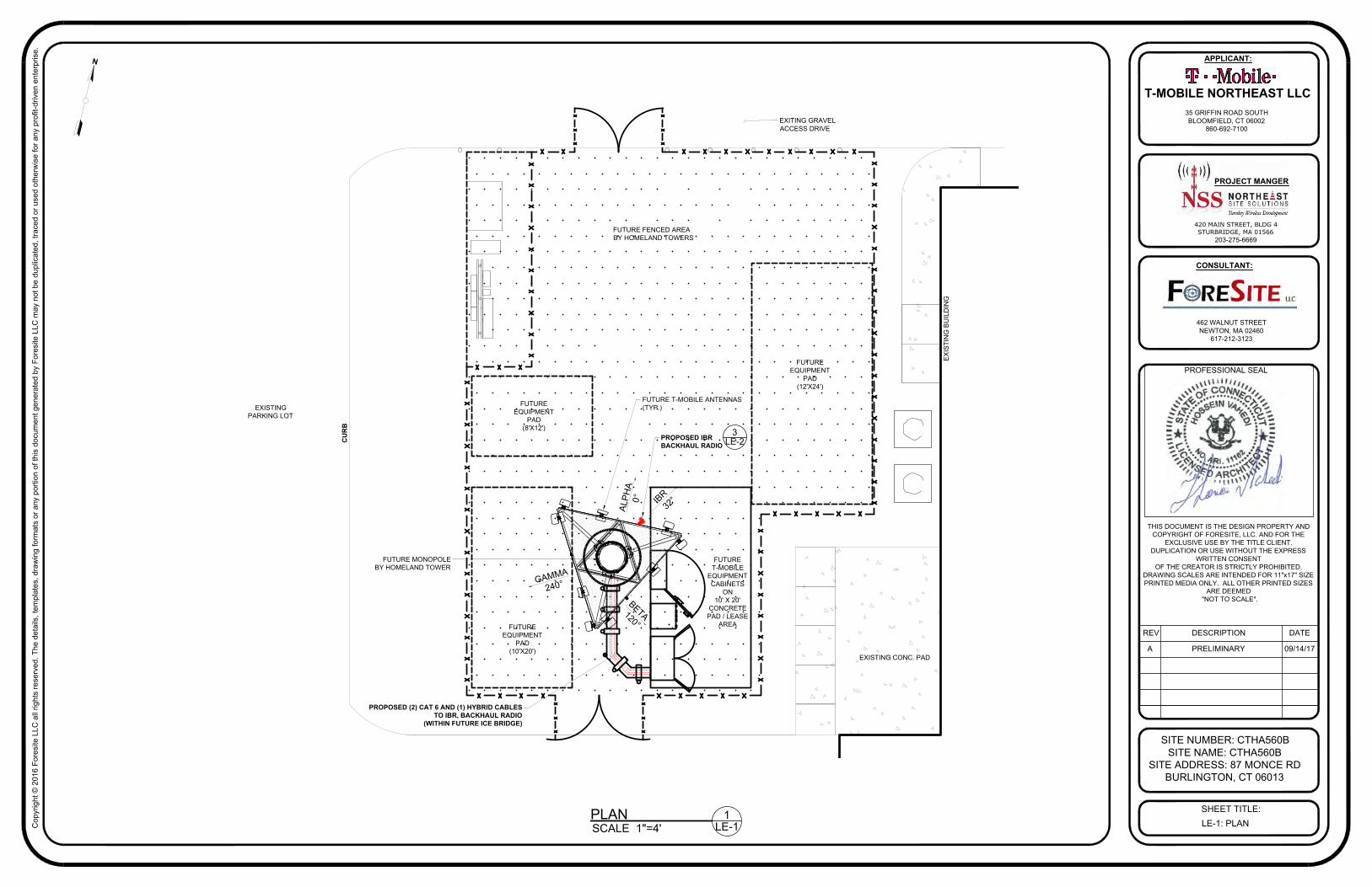
LE-1: PLAN
N
FUTURE MONOPOLEBY HOMELAND TOWER
FUTUREEQUIPMENT
PAD(12'X24')
FUTUREEQUIPMENT
PAD(8'X12')
FUTUREEQUIPMENT
PAD(10'X20')
FUTURET-MOBILE
EQUIPMENTCABINETS
ON10' X 20'
CONCRETEPAD / LEASE
AREA
CU
RB
FUTURE FENCED AREABY HOMELAND TOWERS
EX
ISTI
NG
BU
ILD
ING
PROPOSED (2) CAT 6 AND (1) HYBRID CABLESTO IBR, BACKHAUL RADIO
(WITHIN FUTURE ICE BRIDGE)
PLANSCALE 1"=4'
1LE-1
PROPOSED IBRBACKHAUL RADIO
FUTURE T-MOBILE ANTENNAS(TYP.)
3LE-2
GAMMA
240°
ALPH
A 0
°
BETA 120°
IBR 32
°
EXITING GRAVELACCESS DRIVE
EXISTING CONC. PAD
EXISTINGPARKING LOT

420 MAIN STREET, BLDG 4STURBRIDGE, MA 01566
203-275-6669
462 WALNUT STREETNEWTON, MA 02460
617-212-3123
THIS DOCUMENT IS THE DESIGN PROPERTY ANDCOPYRIGHT OF FORESITE, LLC. AND FOR THE
EXCLUSIVE USE BY THE TITLE CLIENT.DUPLICATION OR USE WITHOUT THE EXPRESS
WRITTEN CONSENTOF THE CREATOR IS STRICTLY PROHIBITED.
DRAWING SCALES ARE INTENDED FOR 11"x17" SIZEPRINTED MEDIA ONLY. ALL OTHER PRINTED SIZES
ARE DEEMED "NOT TO SCALE".
SITE NUMBER: CTHA560BSITE NAME: CTHA560B
SITE ADDRESS: 87 MONCE RDBURLINGTON, CT 06013
SHEET TITLE:
REV DESCRIPTION DATE
A PRELIMINARY 09/14/17
PROJECT MANGER
CONSULTANT:
APPLICANT:
T-MOBILE NORTHEAST LLC35 GRIFFIN ROAD SOUTHBLOOMFIELD, CT 06002
860-692-7100
Cop
yrig
ht ©
201
6 Fo
resi
te L
LC a
ll rig
hts
rese
rved
. The
det
ails
, tem
plat
es, d
raw
ing
form
ats
or a
ny p
ortio
n of
this
doc
umen
t gen
erat
ed b
y Fo
resi
te L
LC m
ay n
ot b
e du
plic
ated
, tra
ced
or u
sed
othe
rwis
e fo
r any
pro
fit-d
riven
ent
erpr
ise.
PROFESSIONAL SEAL
LE-2: ELEVATION AND DETAILSELEVATION SCALE 1-1/2"=1'-0"
TOP OF MONOPOLE ELEV.= 120'± (AGL)
CENTER OFT-MOBILE ANTENNAS
ELEV.= 100'± (AGL)
CENTER OFAT&T ANTENNAS
ELEV.= 110'± (AGL)
CENTER OF ANTENNAS BY OTHERS
ELEV.= 90'± (AGL)
CENTER OF ANTENNAS BY OTHERS
ELEV.= 80'± (AGL)
TOP OF AIR TERMINAL ELEV.= 126'± (AGL)
TOP OF ANTENNAS ELEV.= 141'± (AGL)
FUTURE T-MOBILE ANTENNAS(TYP.)
FUTURE T-MOBILE 10' X 20'CONCRETE PAD/LEASE AREA
1LE-2
FUTURE MONOPOLEBY HOMELAND TOWERS
N
FUTURE TOWN OF BURLINGTONMUNICIPAL WHIP ANTENNAS
(1) 22' AND (2) 21'
TOP OF ANTENNAS ELEV.= 143'± (AGL)
FUTURE T-MOBILEEQUIPMENT CABINETSON CONC. PAD
FUTURE CHAIN LINKFENCED COMPOUND BYHOMELAND TOWER
PROPOSED IBRBACKHAUL RADIO (AZ.:32°)
4LE-1
PROPOSED (2) CAT 6 AND (1) HYBRID CABLES(TO IBR, BACKHAUL RADIO)
3LE-2
7.87"
10.2
4"
3.54"
3.54
"
7.87"
MANUFACTURER: FASTBACKMODEL: IBR 1300FOOTPRINT: 10.24"HX7.87"WX3.54"DWEIGHT: 8.82 LBS
BACKHAUL RADION.T.S
GAMMA
240°
ALPH
A 0
°
BETA 120°
IBR 32
°
PROPOSED IBRBACKHAUL RADIO
FUTURE T-MOBILE ANTENNAS(TYP.)
2LE-2
ANTENNA PLANN.T.S
3LE-2

Exhibit D


Exhibit E

EBI Consulting environmental | engineering | due diligence
21 B Street . Burlington, MA 01803 . Tel: (781) 273.2500 . Fax: (781) 273.3311
RADIO FREQUENCY EMISSIONS ANALYSIS REPORT EVALUATION OF HUMAN EXPOSURE POTENTIAL
TO NON-IONIZING EMISSIONS
T-Mobile Existing Facility
Site ID: CTHA560B
CTHA560B 87 Monce Road
Burlington, CT 06013
September 27, 2017
EBI Project Number: 6217004212
Site Compliance Summary
Compliance Status: COMPLIANT
Site total MPE% of FCC general population
allowable limit:
6.868%

EBI Consulting environmental | engineering | due diligence
21 B Street . Burlington, MA 01803 . Tel: (781) 273.2500 . Fax: (781) 273.3311
September 27, 2017
T-Mobile USA Attn: Jason Overbey, RF Manager 35 Griffin Road South Bloomfield, CT 06002
Emissions Analysis for Site: CTHA560B – CTHA560B
EBI Consulting was directed to analyze the proposed T-Mobile facility located at 87 Monce Road, Burlington, CT, for the purpose of determining whether the emissions from the Proposed T-Mobile Antenna Installation located on this property are within specified federal limits.
All information used in this report was analyzed as a percentage of current Maximum Permissible Exposure (% MPE) as listed in the FCC OET Bulletin 65 Edition 97-01and ANSI/IEEE Std C95.1. The FCC regulates Maximum Permissible Exposure in units of microwatts per square centimeter (W/cm2). The number of W/cm2 calculated at each sample point is called the power density. The exposure limit for power density varies depending upon the frequencies being utilized. Wireless Carriers and Paging Services use different frequency bands each with different exposure limits, therefore it is necessary to report results and limits in terms of percent MPE rather than power density.
All results were compared to the FCC (Federal Communications Commission) radio frequency exposure rules, 47 CFR 1.1307(b)(1) – (b)(3), to determine compliance with the Maximum Permissible Exposure (MPE) limits for General Population/Uncontrolled environments as defined below.
General population/uncontrolled exposure limits apply to situations in which the general population may be exposed or in which persons who are exposed as a consequence of their employment may not be made fully aware of the potential for exposure or cannot exercise control over their exposure. Therefore, members of the general population would always be considered under this category when exposure is not employment related, for example, in the case of a telecommunications tower that exposes persons in a nearby residential area.
Population exposure to radio frequencies is regulated and enforced in units of microwatts per square centimeter (μW/cm2). The general population exposure limit for the 700 MHz Band is approximately 467 μW/cm2, and the general population exposure limit for the 1900 MHz (PCS), 2100 MHz (AWS) and 5 GHz microwave bands is 1000 μW/cm2. Because each carrier will be using different frequency bands, and each frequency band has different exposure limits, it is necessary to report percent of MPE rather than power density.
EBI Consulting environmental | engineering | due diligence
21 B Street . Burlington, MA 01803 . Tel: (781) 273.2500 . Fax: (781) 273.3311
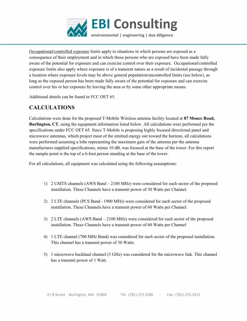
Occupational/controlled exposure limits apply to situations in which persons are exposed as a consequence of their employment and in which those persons who are exposed have been made fully aware of the potential for exposure and can exercise control over their exposure. Occupational/controlled exposure limits also apply where exposure is of a transient nature as a result of incidental passage through a location where exposure levels may be above general population/uncontrolled limits (see below), as long as the exposed person has been made fully aware of the potential for exposure and can exercise control over his or her exposure by leaving the area or by some other appropriate means.
Additional details can be found in FCC OET 65.
CALCULATIONS
Calculations were done for the proposed T-Mobile Wireless antenna facility located at 87 Monce Road, Burlington, CT, using the equipment information listed below. All calculations were performed per the specifications under FCC OET 65. Since T-Mobile is proposing highly focused directional panel and microwave antennas, which project most of the emitted energy out toward the horizon, all calculations were performed assuming a lobe representing the maximum gain of the antenna per the antenna manufactures supplied specifications, minus 10 dB, was focused at the base of the tower. For this report the sample point is the top of a 6-foot person standing at the base of the tower.
For all calculations, all equipment was calculated using the following assumptions:
1) 2 UMTS channels (AWS Band – 2100 MHz) were considered for each sector of the proposedinstallation. These Channels have a transmit power of 30 Watts per Channel.
2) 2 LTE channels (PCS Band - 1900 MHz) were considered for each sector of the proposedinstallation. These Channels have a transmit power of 60 Watts per Channel.
3) 2 LTE channels (AWS Band – 2100 MHz) were considered for each sector of the proposedinstallation. These Channels have a transmit power of 60 Watts per Channel
4) 1 LTE channel (700 MHz Band) was considered for each sector of the proposed installation.This channel has a transmit power of 30 Watts.
5) 1 microwave backhaul channel (5 GHz) was considered for the microwave link. This channelhas a transmit power of 1 Watt.
EBI Consulting environmental | engineering | due diligence
21 B Street . Burlington, MA 01803 . Tel: (781) 273.2500 . Fax: (781) 273.3311
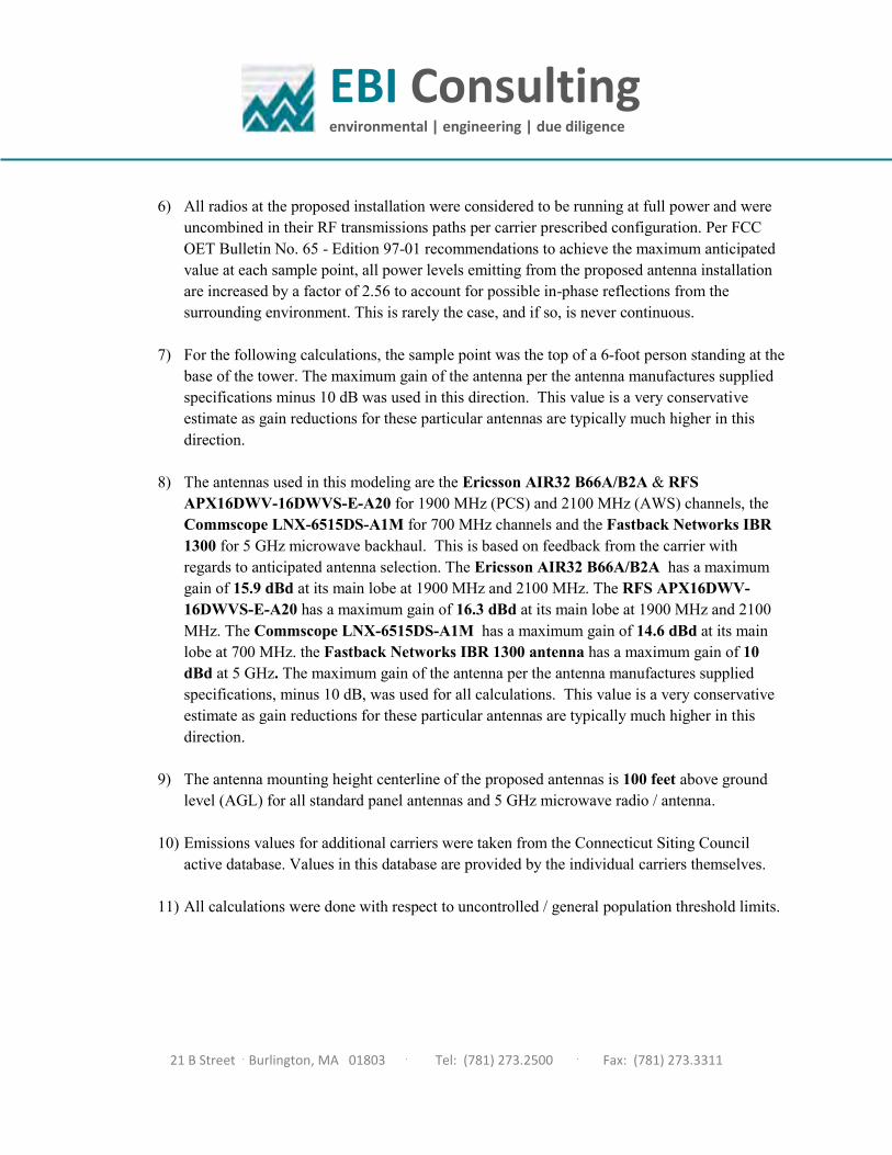
6) All radios at the proposed installation were considered to be running at full power and wereuncombined in their RF transmissions paths per carrier prescribed configuration. Per FCCOET Bulletin No. 65 - Edition 97-01 recommendations to achieve the maximum anticipatedvalue at each sample point, all power levels emitting from the proposed antenna installationare increased by a factor of 2.56 to account for possible in-phase reflections from thesurrounding environment. This is rarely the case, and if so, is never continuous.
7) For the following calculations, the sample point was the top of a 6-foot person standing at thebase of the tower. The maximum gain of the antenna per the antenna manufactures suppliedspecifications minus 10 dB was used in this direction. This value is a very conservativeestimate as gain reductions for these particular antennas are typically much higher in thisdirection.
8) The antennas used in this modeling are the Ericsson AIR32 B66A/B2A & RFSAPX16DWV-16DWVS-E-A20 for 1900 MHz (PCS) and 2100 MHz (AWS) channels, theCommscope LNX-6515DS-A1M for 700 MHz channels and the Fastback Networks IBR1300 for 5 GHz microwave backhaul. This is based on feedback from the carrier withregards to anticipated antenna selection. The Ericsson AIR32 B66A/B2A has a maximumgain of 15.9 dBd at its main lobe at 1900 MHz and 2100 MHz. The RFS APX16DWV-16DWVS-E-A20 has a maximum gain of 16.3 dBd at its main lobe at 1900 MHz and 2100MHz. The Commscope LNX-6515DS-A1M has a maximum gain of 14.6 dBd at its mainlobe at 700 MHz. the Fastback Networks IBR 1300 antenna has a maximum gain of 10dBd at 5 GHz. The maximum gain of the antenna per the antenna manufactures suppliedspecifications, minus 10 dB, was used for all calculations. This value is a very conservativeestimate as gain reductions for these particular antennas are typically much higher in thisdirection.
9) The antenna mounting height centerline of the proposed antennas is 100 feet above groundlevel (AGL) for all standard panel antennas and 5 GHz microwave radio / antenna.
10) Emissions values for additional carriers were taken from the Connecticut Siting Councilactive database. Values in this database are provided by the individual carriers themselves.
11) All calculations were done with respect to uncontrolled / general population threshold limits.
EBI Consulting environmental | engineering | due diligence
21 B Street . Burlington, MA 01803 . Tel: (781) 273.2500 . Fax: (781) 273.3311
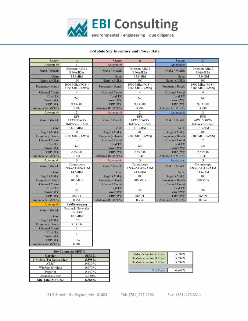
T-Mobile Site Inventory and Power Data
Sector: A Sector: B Sector: C Antenna #: 1 Antenna #: 1 Antenna #: 1
Make / Model: Ericsson AIR32 B66A/B2A Make / Model: Ericsson AIR32
B66A/B2A Make / Model: Ericsson AIR32 B66A/B2A
Gain: 15.9 dBd Gain: 15.9 dBd Gain: 15.9 dBd Height (AGL): 100 Height (AGL): 100 Height (AGL): 100
Frequency Bands 1900 MHz (PCS) / 2100 MHz (AWS) Frequency Bands 1900 MHz (PCS) /
2100 MHz (AWS) Frequency Bands 1900 MHz (PCS) / 2100 MHz (AWS)
Channel Count 4 Channel Count 4 Channel Count 4 Total TX
Power(W): 240 Total TX Power(W): 240 Total TX
Power(W): 240
ERP (W): 9,337.08 ERP (W): 9,337.08 ERP (W): 9,337.08 Antenna A1 MPE% 3.799 Antenna B1 MPE% 3.799 Antenna C1 MPE% 3.799
Antenna #: 2 Antenna #: 2 Antenna #: 2
Make / Model: RFS
APX16DWV-16DWVS-E-A20
Make / Model: RFS
APX16DWV-16DWVS-E-A20
Make / Model: RFS
APX16DWV-16DWVS-E-A20
Gain: 16.3 dBd Gain: 16.3 dBd Gain: 16.3 dBd Height (AGL): 100 Height (AGL): 100 Height (AGL): 100
Frequency Bands 2100 MHz (AWS) Frequency Bands 2100 MHz (AWS) Frequency Bands 2100 MHz (AWS) Channel Count 3 Channel Count 2 Channel Count 2
Total TX Power(W): 60 Total TX
Power(W): 60 Total TX Power(W): 60
ERP (W): 2,559.48 ERP (W): 2,559.48 ERP (W): 2,559.48 Antenna A2 MPE% 1.041 Antenna B2 MPE% 1.041 Antenna C2 MPE% 1.041
Antenna #: 3 Antenna #: 3 Antenna #: 3
Make / Model: Commscope LNX-6515DS-A1M Make / Model: Commscope
LNX-6515DS-A1M Make / Model: Commscope LNX-6515DS-A1M
Gain: 14.6 dBd Gain: 14.6 dBd Gain: 14.6 dBd Height (AGL): 100 Height (AGL): 100 Height (AGL): 100
Frequency Bands 700 MHz Frequency Bands 700 MHz Frequency Bands 700 MHz Channel Count 1 Channel Count 1 Channel Count 1
Total TX Power(W): 30 Total TX
Power(W): 30 Total TX Power(W): 30
ERP (W): 865.21 ERP (W): 865.21 ERP (W): 865.21 Antenna A3 MPE% 0.754 Antenna B3 MPE% 0.754 Antenna C3 MPE% 0.754
Antenna #: 4 (Microwave)
Make / Model: Fastback Networks IBR 1300
Gain: 10.0 dBd Height (AGL): 125
Frequency Bands 5.0 GHz Channel Count 1
Total TX Power(W): 1
ERP (W): 10 W Antenna A4 MPE% 0.004
Site Composite MPE% Carrier MPE%
T-Mobile (Per Sector Max) 5.598% AT&T 0.630 %
WinStar Wireless 0.070 % PageNet 0.140 %
Broadcast Video 0.430% Site Total MPE %: 6.868%
T-Mobile Sector A Total: 5.598% T-Mobile Sector B Total: 5.594% T-Mobile Sector C Total: 5.594%
Site Total: 6.868%

EBI Consulting environmental | engineering | due diligence
21 B Street . Burlington, MA 01803 . Tel: (781) 273.2500 . Fax: (781) 273.3311
T-Mobile Per Sector Maximum Power Values
T-Mobile _Max Values per sector (Sector A)
# Channels
Watts ERP (Per Channel)
Height (feet)
Total Power Density
(W/cm2)
Frequency (MHz)
Allowable MPE
(W/cm2)
Calculated % MPE
T-Mobile AWS - 2100 MHz LTE 2 2,334.27 100 18.99 AWS - 2100 MHz 1000 1.899%
T-Mobile PCS - 1900 MHz LTE 2 2,334.27 100 18.99 PCS - 1900 MHz 1000 1.899%
T-Mobile AWS - 2100 MHz UMTS 2 1,279.74 100 10.41 AWS - 2100 MHz 1000 1.041%
T-Mobile 700 MHz LTE 1 865.21 100 3.52 700 MHz 467 0.754%
T-Mobile 5 GHz MW
NOTE: Totals may vary by 0.001% due to summing of remainders
1 10.00 100 0.04 5 GHz 1000 0.004% Total*: 5.598%

EBI Consulting environmental | engineering | due diligence
21 B Street . Burlington, MA 01803 . Tel: (781) 273.2500 . Fax: (781) 273.3311
Summary
All calculations performed for this analysis yielded results that were within the allowable limits for general population exposure to RF Emissions.
The anticipated maximum composite contributions from the T-Mobile facility as well as the site composite emissions value with regards to compliance with FCC’s allowable limits for general population exposure to RF Emissions are shown here:
T-Mobile Sector Power Density Value (%) Sector A: 5.598% Sector B: 5.594% Sector C: 5.594%
T-Mobile Per Sector Maximum: 5.598%
Site Total: 6.868%
Site Compliance Status: COMPLIANT
The anticipated composite MPE value for this site assuming all carriers present is 6.868% of the allowable FCC established general population limit sampled at the ground level. This is based upon values listed in the Connecticut Siting Council database for existing carrier emissions.
FCC guidelines state that if a site is found to be out of compliance (over allowable thresholds), that carriers over a 5% contribution to the composite value will require measures to bring the site into compliance. For this facility, the composite values calculated were well within the allowable 100% threshold standard per the federal government.

Exhibit