exhaust system - catalytic converter-1.6l duratorq-tdci (74kw-100ps 81kw-110ps) - dv 110 ps
DESCRIPTION
Exhaust System - Catalytic Converter-1.6L Duratorq-TDCi (74kW-100PS 81kW-110PS) - DV 110 PSTRANSCRIPT
Exhaust System - Catalytic Converter—1.6L
Duratorq-TDCi (74kW/100PS 81kW/110PS) - DV
110 PS, VIN Plate Emission Level Code: V
Focus 2004.75 (07/2004-)
Print Report An Error
Removal and Installation
Special Tool(s)
General Equipment
Materials
Specification
SA-M1C9107-A
3. Remove the components in the order indicated in the following illustration(s) and table(s).
Remover/Installer, Coolant Hose Clamp
303-397
Angle Grinder - General Purpose
Name
Grease
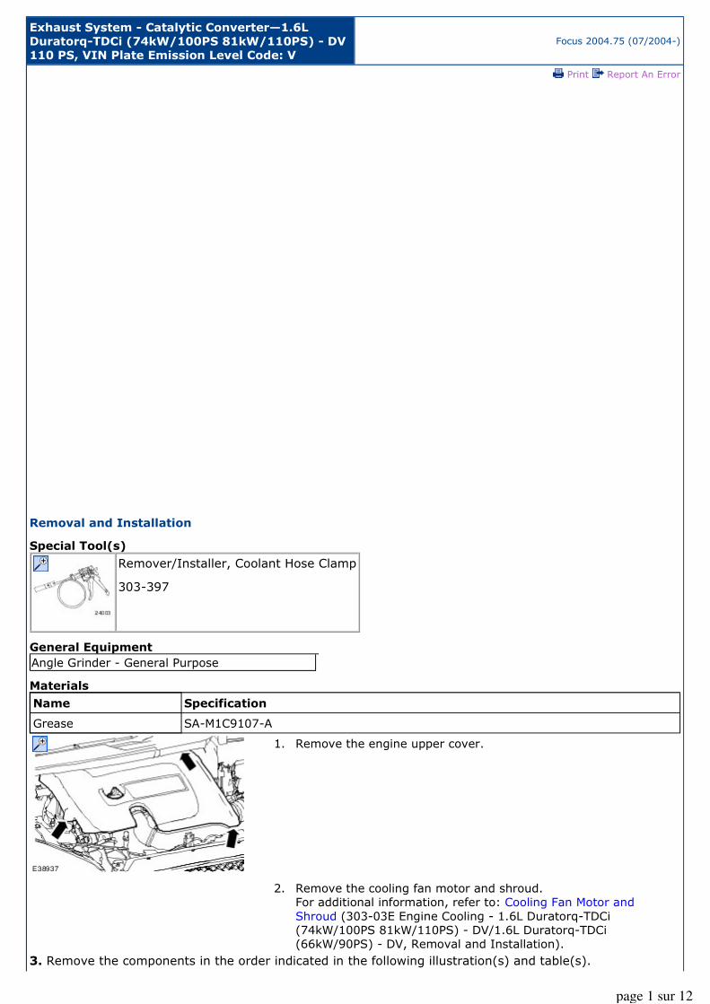
1. Remove the engine upper cover.
2. Remove the cooling fan motor and shroud.
For additional information, refer to: Cooling Fan Motor and
Shroud (303-03E Engine Cooling - 1.6L Duratorq-TDCi
(74kW/100PS 81kW/110PS) - DV/1.6L Duratorq-TDCi
(66kW/90PS) - DV, Removal and Installation).
page 1 sur 12
Description
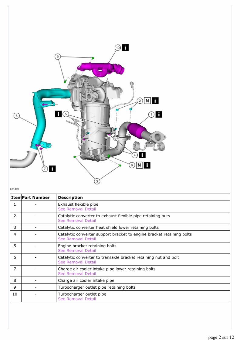
Exhaust flexible pipe See Removal Detail
Catalytic converter to exhaust flexible pipe retaining nuts
See Removal Detail
Catalytic converter heat shield lower retaining bolts
Catalytic converter support bracket to engine bracket retaining bolts
See Removal Detail
Engine bracket retaining bolts
See Removal Detail
Catalytic converter to transaxle bracket retaining nut and bolt
See Removal Detail
Charge air cooler intake pipe lower retaining bolts
See Removal Detail
Charge air cooler intake pipe
Turbocharger outlet pipe retaining bolts
Turbocharger outlet pipe
See Removal Detail
Item
1
2
3
4
5
6
7
8
9
10
Part Number
-
-
-
-
-
-
-
-
-
-
page 2 sur 12
Description
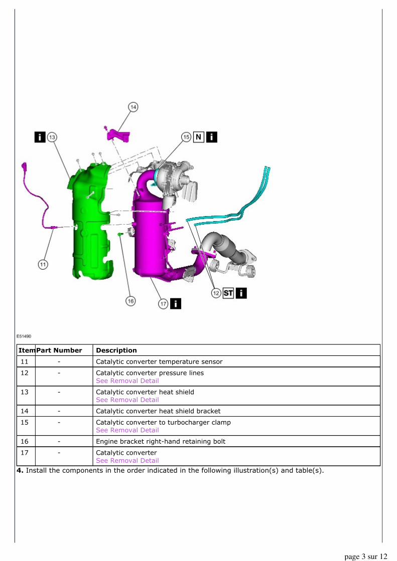
Catalytic converter temperature sensor
Catalytic converter pressure lines
See Removal Detail
Catalytic converter heat shield
See Removal Detail
Catalytic converter heat shield bracket
Catalytic converter to turbocharger clamp
See Removal Detail
Engine bracket right-hand retaining bolt
Catalytic converter
See Removal Detail
4. Install the components in the order indicated in the following illustration(s) and table(s).
Item
11
12
13
14
15
16
17
Part Number
-
-
-
-
-
-
-
page 3 sur 12
Description
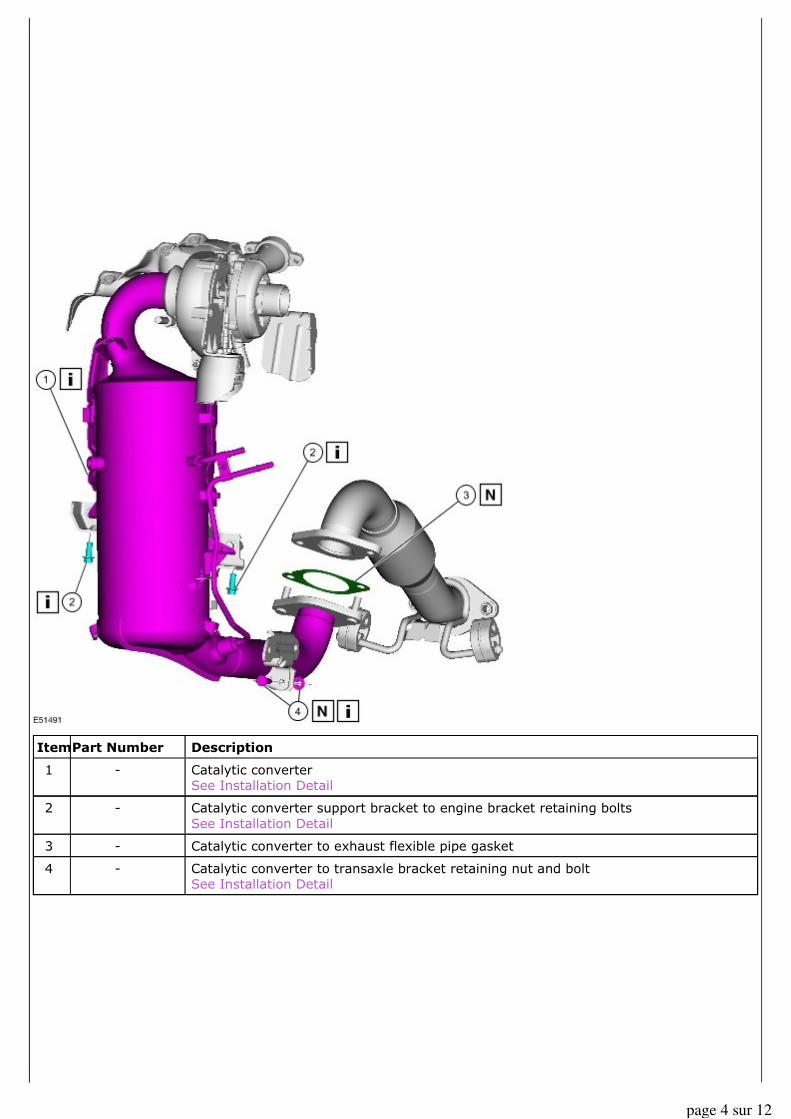
Catalytic converter
See Installation Detail
Catalytic converter support bracket to engine bracket retaining bolts
See Installation Detail
Catalytic converter to exhaust flexible pipe gasket
Catalytic converter to transaxle bracket retaining nut and bolt
See Installation Detail
Item
1
2
3
4
Part Number
-
-
-
-
page 4 sur 12
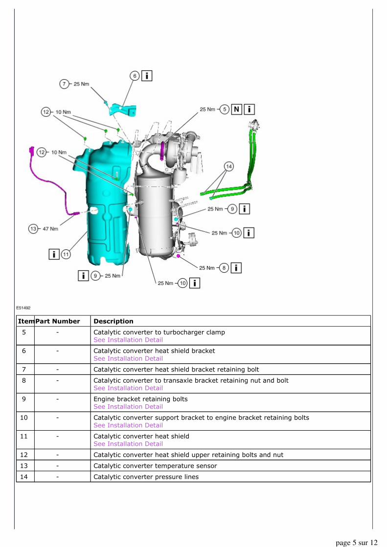
Description
Catalytic converter to turbocharger clamp See Installation Detail
Catalytic converter heat shield bracket
See Installation Detail
Catalytic converter heat shield bracket retaining bolt
Catalytic converter to transaxle bracket retaining nut and bolt
See Installation Detail
Engine bracket retaining bolts
See Installation Detail
Catalytic converter support bracket to engine bracket retaining bolts
See Installation Detail
Catalytic converter heat shield See Installation Detail
Catalytic converter heat shield upper retaining bolts and nut
Catalytic converter temperature sensor
Catalytic converter pressure lines
Item
5
6
7
8
9
10
11
12
13
14
Part Number
-
-
-
-
-
-
-
-
-
-
page 5 sur 12
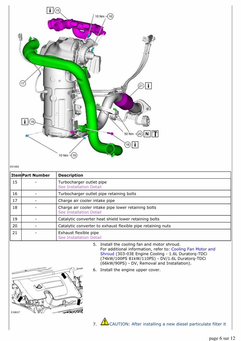
Description
Turbocharger outlet pipe
See Installation Detail
Turbocharger outlet pipe retaining bolts
Charge air cooler intake pipe
Charge air cooler intake pipe lower retaining bolts
See Installation Detail
Catalytic converter heat shield lower retaining bolts
Catalytic converter to exhaust flexible pipe retaining nuts
Exhaust flexible pipe
See Installation Detail
Item
15
16
17
18
19
20
21
5. Install the cooling fan and motor shroud.
For additional information, refer to: Cooling Fan Motor and Shroud (303-03E Engine Cooling - 1.6L Duratorq-TDCi
(74kW/100PS 81kW/110PS) - DV/1.6L Duratorq-TDCi (66kW/90PS) - DV, Removal and Installation).
6. Install the engine upper cover.
7. CAUTION: After installing a new diesel particulate filter it
Part Number
-
-
-
-
-
-
-
page 6 sur 12
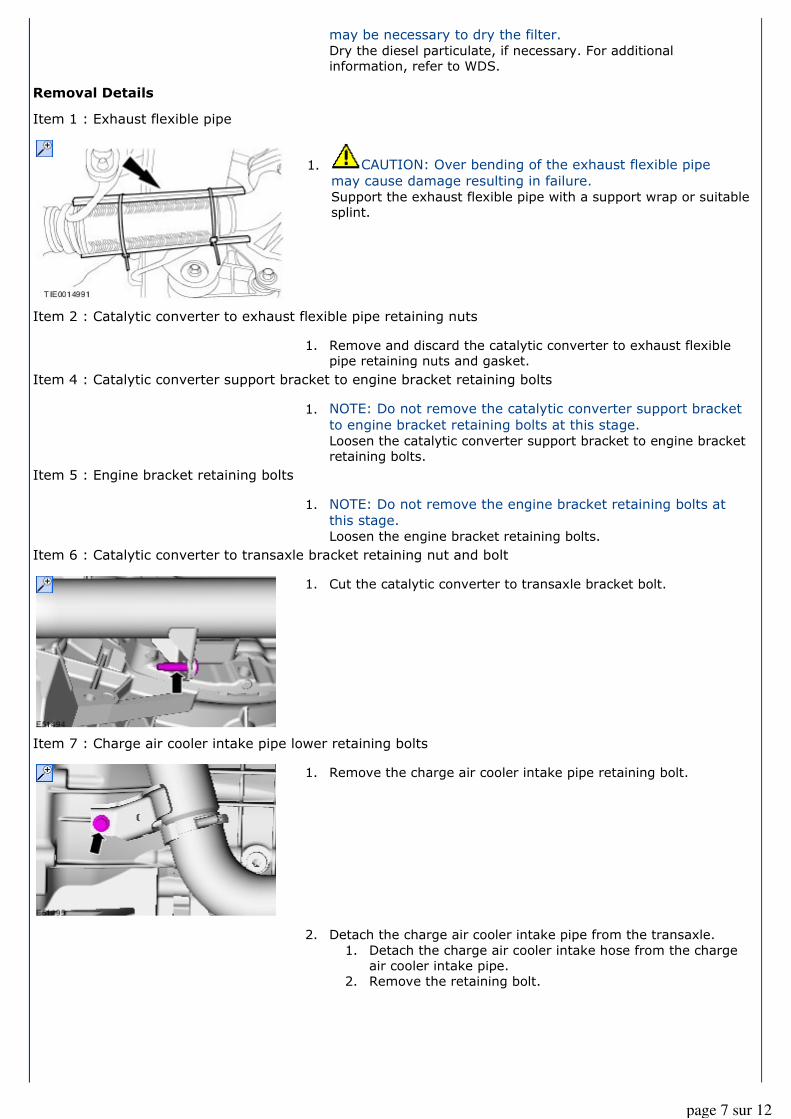
Removal Details
Item 1 : Exhaust flexible pipe
Item 2 : Catalytic converter to exhaust flexible pipe retaining nuts
Item 4 : Catalytic converter support bracket to engine bracket retaining bolts
Item 5 : Engine bracket retaining bolts
Item 6 : Catalytic converter to transaxle bracket retaining nut and bolt
Item 7 : Charge air cooler intake pipe lower retaining bolts
may be necessary to dry the filter. Dry the diesel particulate, if necessary. For additional
information, refer to WDS.
1. CAUTION: Over bending of the exhaust flexible pipe
may cause damage resulting in failure. Support the exhaust flexible pipe with a support wrap or suitable
splint.
1. Remove and discard the catalytic converter to exhaust flexible
pipe retaining nuts and gasket.
1. NOTE: Do not remove the catalytic converter support bracket
to engine bracket retaining bolts at this stage. Loosen the catalytic converter support bracket to engine bracket
retaining bolts.
1. NOTE: Do not remove the engine bracket retaining bolts at
this stage. Loosen the engine bracket retaining bolts.
1. Cut the catalytic converter to transaxle bracket bolt.
1. Remove the charge air cooler intake pipe retaining bolt.
2. Detach the charge air cooler intake pipe from the transaxle.
1. Detach the charge air cooler intake hose from the charge air cooler intake pipe.
2. Remove the retaining bolt.
page 7 sur 12
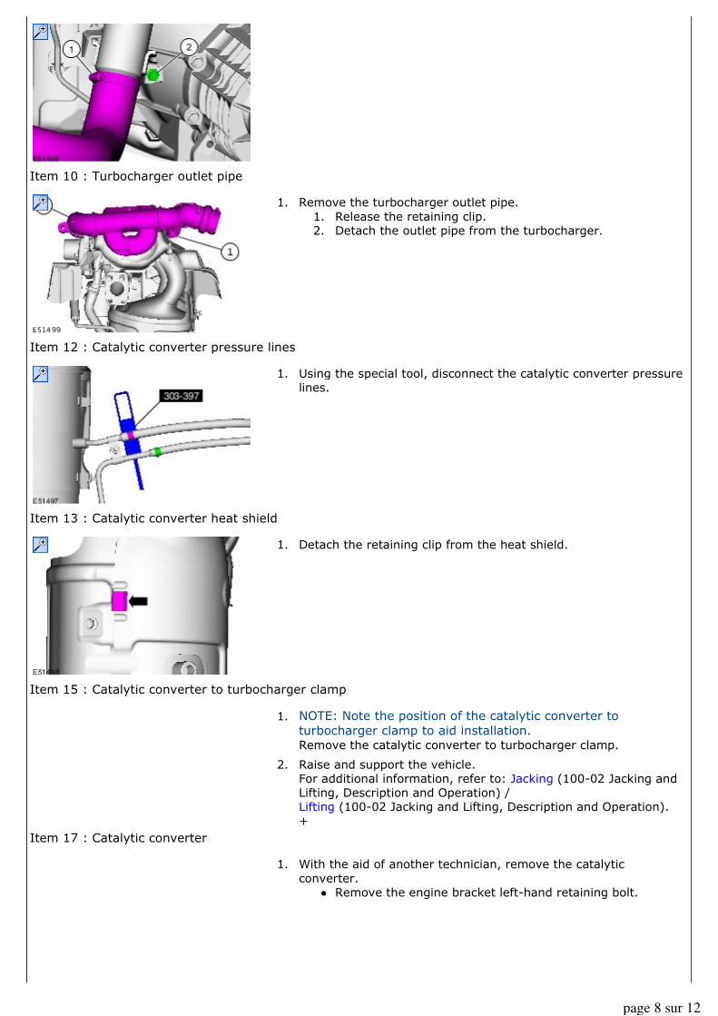
Item 10 : Turbocharger outlet pipe
Item 12 : Catalytic converter pressure lines
Item 13 : Catalytic converter heat shield
Item 15 : Catalytic converter to turbocharger clamp
Item 17 : Catalytic converter
1. Remove the turbocharger outlet pipe.
1. Release the retaining clip. 2. Detach the outlet pipe from the turbocharger.
1. Using the special tool, disconnect the catalytic converter pressure
lines.
1. Detach the retaining clip from the heat shield.
1. NOTE: Note the position of the catalytic converter to
turbocharger clamp to aid installation. Remove the catalytic converter to turbocharger clamp.
2. Raise and support the vehicle. For additional information, refer to: Jacking (100-02 Jacking and Lifting, Description and Operation) /
Lifting (100-02 Jacking and Lifting, Description and Operation).
+
1. With the aid of another technician, remove the catalytic
converter. � Remove the engine bracket left-hand retaining bolt.
page 8 sur 12
Installation Details
Item 1 : Catalytic converter
2. Remove the engine bracket.
1. NOTE: Do not fully tighten the engine bracket retaining bolts
at this stage. Install the engine bracket.
2. Remove the transaxle bracket.
3. Using a suitable Angle Grinder, remove the bolt from the
transaxle bracket.
4. Install the transaxle bracket.
page 9 sur 12
Item 2 : Catalytic converter support bracket to engine bracket retaining bolts
NOTE: Do not fully tighten the catalytic converter to engine bracket retaining bolts at this stage.
Item 4 : Catalytic converter to transaxle bracket retaining nut and bolt
Item 5 : Catalytic converter to turbocharger clamp
CAUTION: Never use jointing compound forward of the catalytic converter.
NOTE: Make sure the catalytic converter to turbocharger clamp is installed in its original position.
Item 6 : Catalytic converter heat shield bracket
Item 8 : Catalytic converter to transaxle bracket retaining nut and bolt
5. NOTE: Make sure the catalytic converter bracket is on top of
the engine bracket. Align the catalytic converter to the engine bracket
6. NOTE: Make sure the catalytic converter bracket is behind
the transaxle bracket. Align the catalytic converter to the transaxle bracket.
1. NOTE: Do not fully tighten the catalytic converter to
transaxle bracket nut and bolt at this stage. Install the catalytic converter to transaxle bracket retaining nut
and bolt.
2. NOTE: Vehicles built 01/2007 onwards. Install the bracket nuts.
3. Lower the vehicle.
1. NOTE: Make sure that the catalytic converter heat shield
bracket locating tang is correctly located on the catalytic
converter. Install the catalytic converter heat shield bracket.
1. Raise and support the vehicle.
page 10 sur 12
Item 9 : Engine bracket retaining bolts
CAUTION: Make sure the catalytic converter to transaxle bracket retaining nut is tightened before
tightening the engine bracket retaining bolts.
Item 10 : Catalytic converter support bracket to engine bracket retaining bolts
CAUTION: Make sure the engine bracket retaining bolts are tightened before tightening the catalytic
converter support bracket to engine bracket retaining bolts.
Item 11 : Catalytic converter heat shield
Item 15 : Turbocharger outlet pipe
Item 18 : Charge air cooler intake pipe lower retaining bolts
Item 21 : Exhaust flexible pipe
For additional information, refer to: Jacking (100-02 Jacking and Lifting, Description and Operation) /
Lifting (100-02 Jacking and Lifting, Description and Operation).
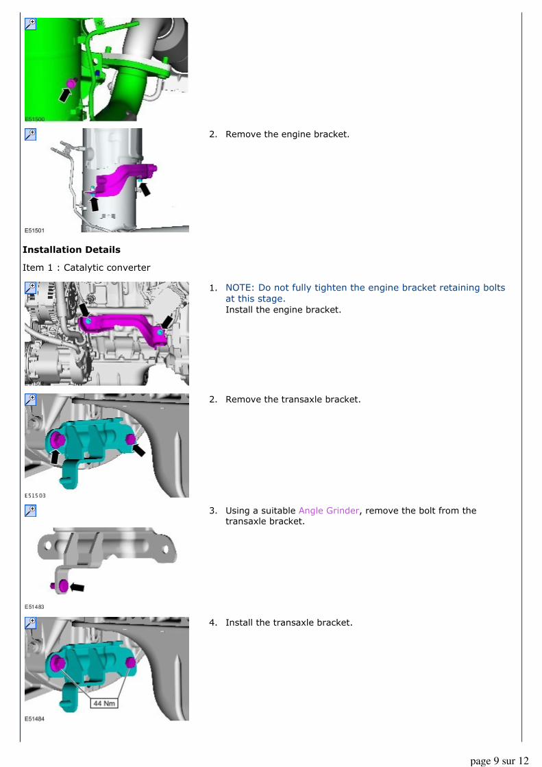
1. NOTE: If the retaining clip is damaged, repair or install a
new retaining clip. Attach the retaining clip to the heat shield.
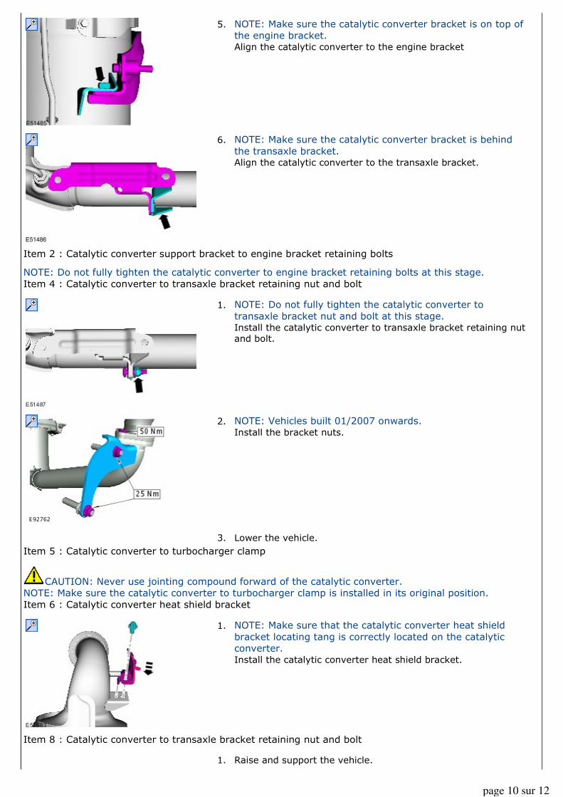
1. Install the turbocharger outlet pipe.
1. Attach the outlet pipe to the turbocharger.
2. Secure the retaining clip.
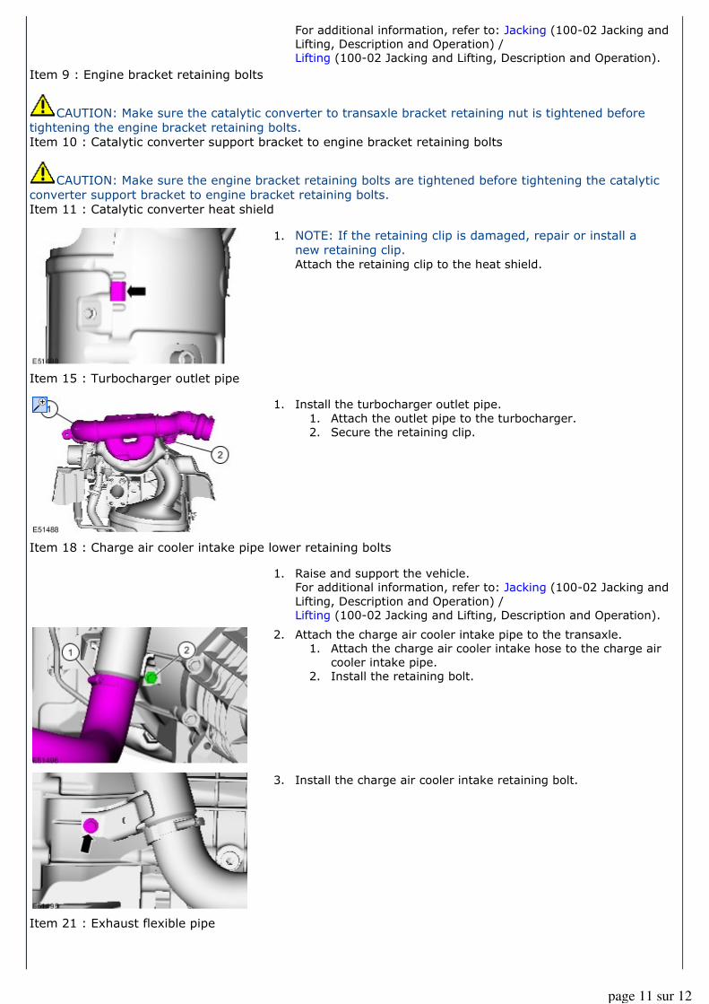
1. Raise and support the vehicle.
For additional information, refer to: Jacking (100-02 Jacking and
Lifting, Description and Operation) / Lifting (100-02 Jacking and Lifting, Description and Operation).
2. Attach the charge air cooler intake pipe to the transaxle.
1. Attach the charge air cooler intake hose to the charge air
cooler intake pipe.
2. Install the retaining bolt.
3. Install the charge air cooler intake retaining bolt.
page 11 sur 12
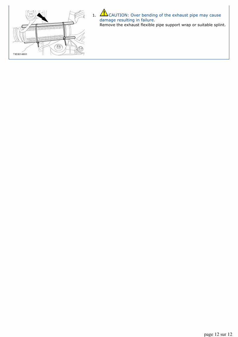
1. CAUTION: Over bending of the exhaust pipe may cause
damage resulting in failure. Remove the exhaust flexible pipe support wrap or suitable splint.
page 12 sur 12