exemption renewal form - exemption 26 annex iv
TRANSCRIPT
1
Exemption Renewal Form - Exemption 26 Annex IV
Date of submission: 02 December 2019 (deadline 20 Dec 2019 as expires 21 June 2021)
This dossier is submitted by COCIR for category 8 medical imaging devices. Exemption 26 of
Annex IV also includes lead solders used to connect to temperature measurement sensors
needed by category 8 equipment and category 9 industrial equipment, which are not in the
scope of this COCIR renewal request, the contact details for these applications are reported
below. Such applications are covered in separate documents that have been submitted with
this dossier.
Attached documentation:
1. CONFIDENTIAL - COCIR quantity calculation Renewal exemption 26
2. Ex 26 lead in temp sensor for cat 8&9
3. CONFIDENTIAL- Addendum to ex 26 lead in temp sensor for cat 8&9
1. Name and contact details
1) Name and contact details of applicant: Medical Imaging Devices
Company: COCIR Tel.: 00327068966
Name: Riccardo Corridori E-Mail: [email protected]
Function: EHS Policy Senior Manager Address: Blvd A. Reyers 80, 1030
Bruxelles
2) Name and contact details of applicant: Category 8&9 – Lead solders to temperature measurement sensors
Company: Lake Shore Cryotronics Tel.: 01-614-212-1537
Name: Betsey Krause E-Mail:
Function: Corporate Compliance
Manager
Address: 575 McCorkle Blvd,
Westerville, OH 43082
2. Reason for application:
Please indicate where relevant:
Request for new exemption in:
Request for amendment of existing exemption in
Request for extension of existing exemption in Annex IV
2
Request for deletion of existing exemption in:
Provision of information referring to an existing specific exemption in:
Annex III Annex IV
No. of exemption in Annex III or IV where applicable: 26 of Annex IV
Proposed or existing wording:
i) Lead in the following applications that are used durably at a temperature below
– 20 °C under normal operating and storage conditions:
(a) solders on printed circuit boards;
(b) termination coatings of electrical and electronic components and
coatings of printed circuit boards;
(c) solders for connecting wires and cables;
(d) solders connecting transducers and sensors.
Duration where applicable:
• Low helium content MRI (<10kg / scanner) Maximum validity period of
at least 7 years
• Standard MRI: Until 30 June 2027
ii) Lead in solders of electrical connections to temperature measurement sensors
in devices which are designed to be used periodically at temperatures below – 150
°C.
Duration where applicable:
• Categories 8 and 9 equipment: Maximum validity period of at least 7
years
Other:
3. Summary of the exemption request / revocation request
Medical magnetic resonance imaging (MRI) scanners are large and very complex and
utilise liquid helium cooled superconducting electromagnets. Associated with these
magnets are wires, cables, sensors and control electronics some of which are at
locations where the temperature is very low. Everything inside of the vacuum vessel of
an MRI magnet during normal operation is at ~40K = -233 C (or less) and ~4.2K = -
268.8C (or less). Everything at/on the outer vacuum vessel including service turret
elements must withstand storage conditions to -25 C. During helium filling, ramping,
quenching the service turret elements will experience temperatures below -150C as air
is known to be liquefied in these conditions (Oxygen liquefies at -183C); the service
turret and vent area is at cryogenic temperatures during such periodic operations or
events.
Manufacturers have built MRI circuits using tin/lead and lead-free solders and tested
3
these at realistic use conditions of low temperature and vibration to compare the
reliability with different solders. At low temperatures, the lead-free soldered circuits
failed sooner than the tin/led circuits due to bond failure. It is not possible to determine
whether tin pest failures will occur in the normal lifetime of an MRI because this failure
mode cannot be accelerated and research has shown that this takes at least eight years
to occur. MRI system once installed may be used for 15 – 25 years so published data
on tin pest suggests that there may be a reliability concern with lead-free solders during
this timescale, although this cannot be proven. However, the risk posed by tin pest is
extremely high – if/when it occurs and impacts the entire magnet of the MRI system
which would need to be replaced. The average cost of a single magnet replacement is
>$250,000 which most EU hospitals can ill-afford. This exemption is justified as
reliability of substitute solders is not ensured. MRI scanner designs are reviewed and
modified by manufacturers to improve diagnostic capability and this may also reduce
the amount of lead solders needed in some designs.
The latest magnet design of MRI uses only 7 litres of liquid helium instead of the usual
~1500 litres of liquid helium. This design includes control circuits that are at low
temperature and suffer from vibration and so will continue to need this exemption.
Examples of components with soldered lead connections are contactors that thermally
disconnect the cold components after the magnet has been energized, as well as
temperature and voltage sensors to monitor the condition of the magnet. This will be
required until research can be carried out that determines whether any substitutes exist
that will be reliable for up to 25 years lifetime.
Renewal of exemption 26 for lead in solders to temperature sensors for both category
8 and 9 applications is also requested, but an explanation of this use and justification
of the exemption is provided as separate documents.
4. Technical description of the exemption request / revocation
request
(A) Description of the concerned application:
1. To which EEE is the exemption request/information relevant?
Name of applications or products: Medical Magnetic Resonance Imaging
(MRI) equipment, MRI/PET, MRI/CT.
a. List of relevant categories: (mark more than one where applicable)
4
1 7
2 8
3 9
4 10
5 11
6
b. Please specify if application is in use in other categories to which the
exemption request does not refer: Most uses in Category 9 (such as NMR
spectrometers) are not covered by this request. However renewal for uses in
category 9 (and 8) temperature sensors is included (described in separately
submitted documents)
c. Please specify for equipment of category 8 and 9:
The requested exemption will be applied in
monitoring and control instruments in industry (temperature sensors only)
in-vitro diagnostics
other medical devices or other monitoring and control instruments than
those in industry
2. Which of the six substances is in use in the application/product?
(Indicate more than one where applicable)
Pb Cd Hg Cr-VI PBB PBDE
3. Function of the substance: Lead is used as an alloy constituent in solder
that is used to make electrically and thermally conducting connections that are
stable and reliable at low temperatures
4. Content of substance in homogeneous material (%weight): Typically 36
– 40% by weight
5. Amount of substance entering the EU market annually through application for
which the exemption is requested: Estimated to be <1kg per year
Please supply information and calculations to support stated figure.
This is provided separately as the calculation includes confidential market
information.
6. Name of material/component: Tin / lead solder
5
7. Environmental Assessment:
LCA: Yes
No
(B) In which material and/or component is the RoHS-regulated substance used,
for which you request the exemption or its revocation? What is the function
of this material or component?
Magnetic Resonance Imaging (MRI) is an essential medical diagnostic tool which
is used to examine in very fine detail all parts of the human body including internal
organs, blood vessels, muscles, etc. It uses a large round, very powerful
electromagnet into which the patient is inserted. 3D images of parts of the patient
are obtained by exposing the patient to the powerful magnetic field as well as to
pulsed gradient magnetic fields for spatial encoding and electromagnetic radio
frequencies that are used to excite the resonance and generate the image. Image
quality depends on the strength of the magnetic field and so magnetic fields of up
to 7 Tesla (7T) are used clinically, and even higher (>7T) magnetic fields are used
for research applications. The signal to noise ratio in MRI increases (improving the
image quality) with magnetic field strength, thus there is the need for high magnetic
field strength.
It is possible to obtain the very powerful magnetic field in a relatively compact
space only by using superconducting electromagnet coils that must be cooled to
the temperature of liquid helium (4.2K = -269°C). Construction of the cold elements
of the magnet require many wires, cables, speciality components such as current
switches, heaters for emergency use, circuits and sensors that are all connected
electrically and thermally with tin/lead solder. Control of the magnetic field requires
complex electronics, such as temperature sensors and control electronics, also
additional compensation coils that adjust and stabilise the magnetic field to
optimise image quality. Each MRI manufacturer has their own proprietary designs
and each design of MRI has a unique combination of performance parameters.
Most of the magnet related electronics, wires, cables, specialty components are in
cold regions in or in thermal communication with the bath of liquid helium or in the
radiation shield. Thus all see over their lifetime temperature of ~4.2K (- 269C).
In principal, any solder bonds that are within 1 metre of the isocentre of the
electromagnet would be covered by exemption 27 of Annex IV, but some MRI
solder bonds are at below -20°C and located at >1 metre of the isocentre of the
electromagnet so require exemption 26.
MRI rely on high-energy superconducting magnets that operate at liquid helium
temperature (≤4K). Electrical circuitry needs to be located close to the magnets
and liquid helium; this will need to operate reliably at below -20°C for at least 25
years. These include components that are part of the electrical circuit of the
magnet, which are disconnected from the outside world for thermal reasons.
6
Examples are diodes, switches and heaters for quench protection and components
that control the current in the magnet coils to maintain a steady field in the presence
of moving metallic objects outside of the magnet.
Long lifetime, reliable electrical circuits are created using solders because these
have very low electrical resistance and good thermal conduction properties,
including at low temperature and, after many decades of use, have been proven to
be reliable. Solders used to make electrical circuitry must melt at a temperature
that does not damage either the printed circuit boards or the electronic components
and all reliable solder alloys are based on tin. Tin metal however exists as two
allotropic forms: white and grey. At ambient temperature above 13.2°C, such as
occurs in hospitals, tin exists in the white -form. Below 13.2°C, tin can transform
into the brittle grey -form and the transformation causes the solder bonds to
disintegrate and form a grey powder with no electrical connection.
Lead has been added to tin as a constituent of solder for many decades and is
used to make electrical connections that can be used at low temperature at which
they have been found to very significantly retard the phase transformation of tin
and tin-based alloys from the white to grey forms. MRI scanners with tin/lead solder
have been in use for many decades (>30 years) and the tin/lead solder bonds at
low temperature have proven to be reliable during the lifetime of the MRI.
Manufacturers of MRI have carried out research into lead-free soldering of low
temperature electrical connections of MRI since medical devices were included in
scope of the RoHS Directive. Research has shown that early bond failures occur
due to the combination of severe vibration that occurs with MRI and the low
temperatures that make lead-free solders harder and so more brittle than solders
that contain lead. Longer term testing to determine whether tin pest occurs is not
complete so the reliability of low temperature lead-free MRI circuits is not ensured.
COCIR is aware that RoHS exemption 27 of Annex IV will exempt lead in solders
of MRI circuits that are within a 1 metre radius around the isocentre of the magnet
(if it is renewed) and so one way to avoid exemption 26 is to design MRI with all
low temperature bonds at locations that are within the 1m radius of the isocentre
of the magnet. However this is not always possible and so exemption 26 is still
needed for at least some of the uses of MRI circuit solder. With most standard
design MRI, relatively few low temperature solder bonds are located outside of 1m
from the magnets’ isocentre and these include bonds to sensors, contactors,
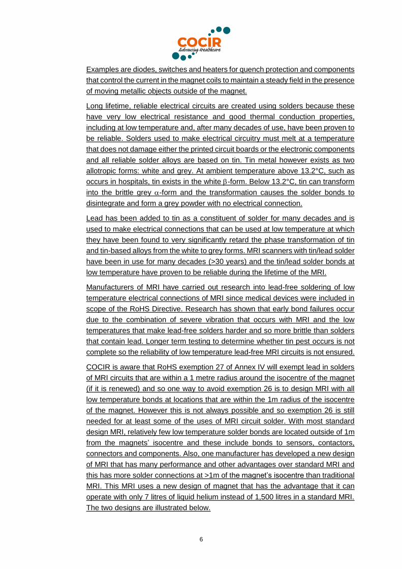
connectors and components. Also, one manufacturer has developed a new design
of MRI that has many performance and other advantages over standard MRI and
this has more solder connections at >1m of the magnet’s isocentre than traditional
MRI. This MRI uses a new design of magnet that has the advantage that it can
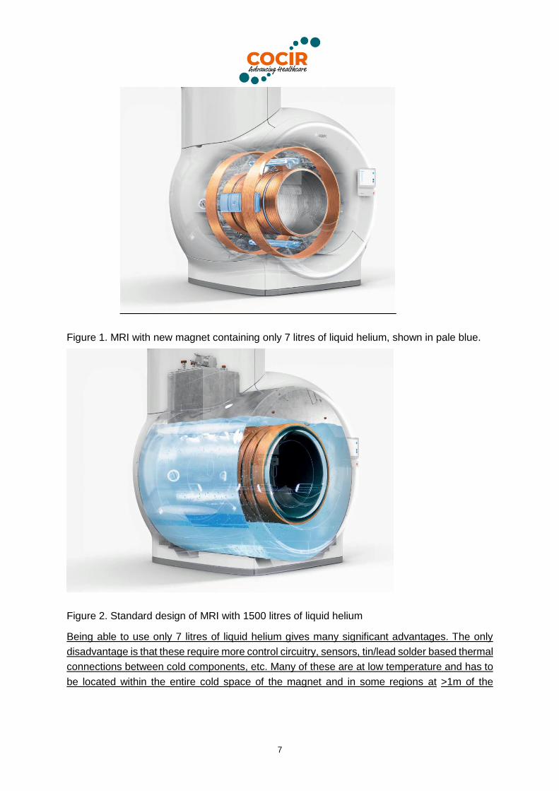
operate with only 7 litres of liquid helium instead of 1,500 litres in a standard MRI.
The two designs are illustrated below.
7
Figure 1. MRI with new magnet containing only 7 litres of liquid helium, shown in pale blue.
Figure 2. Standard design of MRI with 1500 litres of liquid helium
Being able to use only 7 litres of liquid helium gives many significant advantages. The only
disadvantage is that these require more control circuitry, sensors, tin/lead solder based thermal
connections between cold components, etc. Many of these are at low temperature and has to
be located within the entire cold space of the magnet and in some regions at >1m of the
8
magnet’s isocentre with MRI having a 70cm patient bore1. However the advantages of this
design include:
• Helium is a very scarce element on the Earth. MRI scanners consume 20% of the
earth’s available supply and it is expected that demand is likely to increase for all uses
of helium, so an ability to use considerably smaller quantities in each MRI would help
to ensure that MRI scanners can continue to be produced and maintained and patients
treated / diagnosed using this essential diagnostic technique. At the same time, the
environmental impact arising from the extraction, processing and use of this very
scarce element is much reduced.
• Having 1500 litres of liquid helium inside each MRI poses a known safety risk that is
generally mitigated by a vent pipe system. If the magnet quenches >1,000,000 litres of
helium gas is evolved and must safely be vented to atmosphere outside the building.
Over the decades long lifecycle of the MRI the terminus and full path of the vent system
must never become blocked or impeded, otherwise potentially catastrophic failure can
occur due to overpressure. For this reason the MRI customers/sites have the burden
to maintain, inspect, clean as necessary the vent system over the lifecycle. Also, helium
must safely vent if the equipment has to be ramped down (magnet power reduced to
zero), either because a piece of magnetic metal accidentally enters the bore or in an
emergency with a patient. When this happens, some of the liquid helium in standard
MRI vaporises and needs to be vented. With these new magnets, as they contain only
7 litres of liquid helium, if this vaporises, the pressurised helium gas is retained within
the MRI and no venting is required. MRI magnets are relatively heavy (typically 3.7
tonnes) and so are usually located on the ground floor of hospitals. However, many
hospitals are multi-story and the vent outlet must be above the roof. This increases the
disruption to hospitals when MRI are installed as well as increasing the hospital’s costs.
Avoiding a vent system means that the hospitals can spend the money saved on
installing a vent on providing healthcare to patients instead.
• MRI with only 7 litres of liquid helium typically weigh 900kg less than a standard MRI
with the same magnet energy. This is a big advantage, not only in conserving raw
materials, but as the MRI is lighter, it may be possible (depending on floor strength) to
locate the MRI on upper floors of hospitals, which may allow patients to be transferred
from wards to the MRI scanner more quickly in an emergency.
• After a magnet quenches, the time taken to restart the MRI, re-liquefy the helium and
make up for any vented gases, then ramp up the magnetic field is on average 7 days
and can and can be weeks in some world regions with standard MRI due to limited
access and logistics of helium delivery. This poses a health risk to patients that cannot
be scanned while this is being carried out. MRI with 7 litres of liquid helium can be
passively cooled down and then ramped up and be back in operation in about two days
1 MRI are made with various bore diameters. 70cm is larger than many MRI on the market and has the advantage
of being suitable for very large patients as well as being less of an issue with claustrophobic patients. However,
a larger bore means that more circuitry will be at >1m of the magnet’s isocentre
9
after a loss of field and in even less time after a controlled ramp down. A survey of
hospitals found that 60% had an issue with magnetic parts stuck in the bore during a
three year period and so required ramp-down2, so this is a fairly common problem.
This new design of magnet needs permanently installed, energization leads and it has unique
control components inside the magnet (in the cold zone) to ensure a reliable electrical and/or
thermal communication between elements, as well as maintaining minimum heat conduction
into the cold space. Low helium magnets require much more complex control circuitry to
maintain liquid helium and keep the magnet cool and so use more circuits and components
within the cold zone than standard MRI designs.
(C) What are the particular characteristics and functions of the RoHS-regulated
substance that require its use in this material or component?
The solder used to make electrical and thermal connections of MRI must have all of
the following essential characteristics:
• Solder alloy must be stable at temperatures below -20°C for at least 25 years and
must not suffer from the phase transformation known as “tin pest” or bond failure
due to vibration.
• Low electrical resistivity.
• High thermal conductivity.
• Ductile material that is able to withstand intense, high g-force vibration without
suffering from fatigue, fracture or de-bonding.
• Ability to form a strong bond between the printed circuit boards and components
that do not weaken significantly during the expected lifetime of at least 25 years.
• Bonds can be produced at a temperature that does not damage the components or
circuit board.
• It must be possible to produce many thousands of bonds simultaneously with 100%
being of good quality.
• Bonds must be reliable under the high g-force vibration conditions of well over 2g
at a wide range of frequencies. This g-force has been measured on MRI circuits.
5. Information on Possible preparation for reuse or recycling of waste
from EEE and on provisions for appropriate treatment of waste
1) Please indicate if a closed loop system exist for EEE waste of application
exists and provide information of its characteristics (method of collection to
ensure closed loop, method of treatment, etc.)
2 Marketech June 2017 study http://www.marketechcorp.com/
10
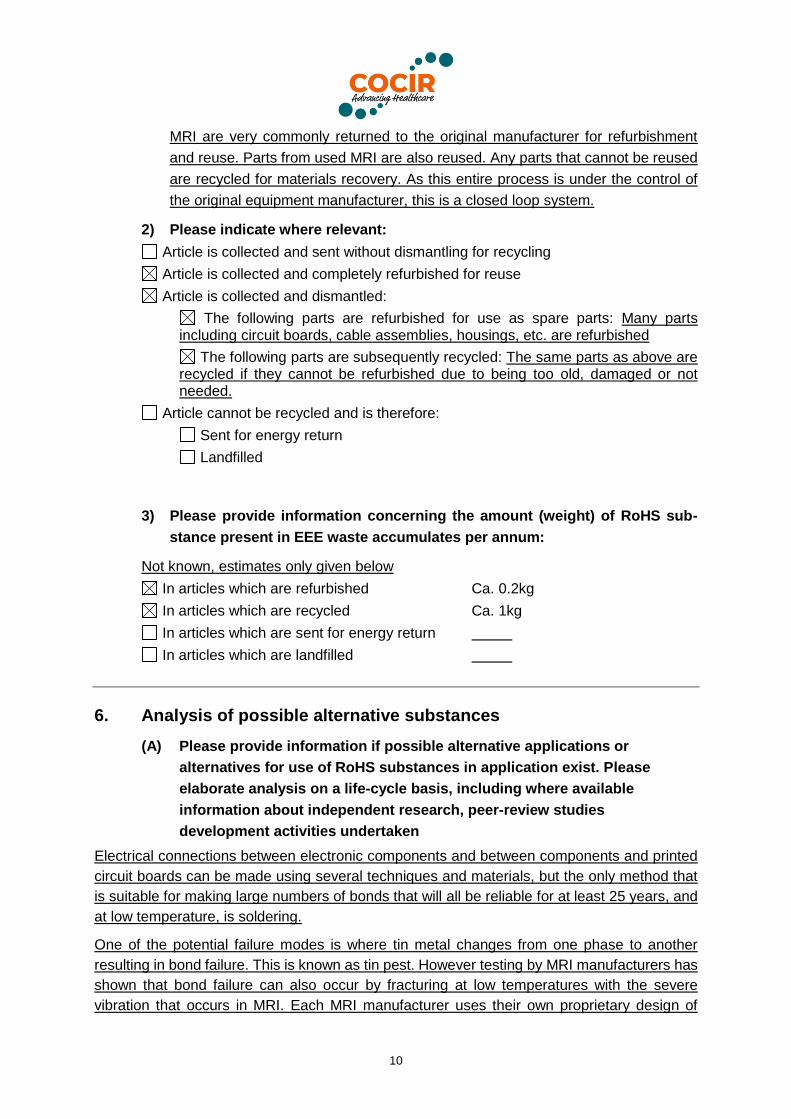
MRI are very commonly returned to the original manufacturer for refurbishment
and reuse. Parts from used MRI are also reused. Any parts that cannot be reused
are recycled for materials recovery. As this entire process is under the control of
the original equipment manufacturer, this is a closed loop system.
2) Please indicate where relevant:
Article is collected and sent without dismantling for recycling
Article is collected and completely refurbished for reuse
Article is collected and dismantled:
The following parts are refurbished for use as spare parts: Many parts including circuit boards, cable assemblies, housings, etc. are refurbished
The following parts are subsequently recycled: The same parts as above are recycled if they cannot be refurbished due to being too old, damaged or not needed.
Article cannot be recycled and is therefore:
Sent for energy return
Landfilled
3) Please provide information concerning the amount (weight) of RoHS sub-
stance present in EEE waste accumulates per annum:
Not known, estimates only given below
In articles which are refurbished Ca. 0.2kg
In articles which are recycled Ca. 1kg
In articles which are sent for energy return
In articles which are landfilled
6. Analysis of possible alternative substances
(A) Please provide information if possible alternative applications or
alternatives for use of RoHS substances in application exist. Please
elaborate analysis on a life-cycle basis, including where available
information about independent research, peer-review studies
development activities undertaken
Electrical connections between electronic components and between components and printed
circuit boards can be made using several techniques and materials, but the only method that
is suitable for making large numbers of bonds that will all be reliable for at least 25 years, and
at low temperature, is soldering.
One of the potential failure modes is where tin metal changes from one phase to another
resulting in bond failure. This is known as tin pest. However testing by MRI manufacturers has
shown that bond failure can also occur by fracturing at low temperatures with the severe
vibration that occurs in MRI. Each MRI manufacturer uses their own proprietary design of
11
magnet and this will affect the location of soldered bonds (i.e. inside or outside of the 1m
isocentre) and also significantly the mass of the magnet. It is known that lighter magnets suffer
from more vibration that heavy magnets. Reducing vibration will improve reliability, but heavier
magnets consume more raw materials and energy for fabrication. An advantage of lighter
magnets is that they can be installed in high-rise hospitals. This can be important in cities
where space is limited. Reducing vibration therefore is not straightforward and can have
undesirable side-effects. In fact, vibrations in MRI are increasing with time due to the higher
gradient performance being used that is driven by an increasing range of clinical applications
and also by the demands for higher scanning speed.
Lead has been shown to significantly retard the “tin pest” phase transformation from white tin
into grey. Research into the rate of transformation shows that some metals accelerate
transformation (such as copper), whereas others retard the phase change (such as lead). Even
trace quantities of impurities can significantly affect the transformation rate. Research also
shows that many other variables, some not well understood, affect tin pest rates and so it is
difficult to compare publications because often the impurity concentrations and other variables
are not measured, but would have a significant impact on rate. The dependence on a wide
variety of poorly understood variables is shown when multiple samples are stored at low
temperature where only some experience tin pest or the time until first signs occur are very
varied.
Some of the metals that may be an alternative to lead that retard the transformation including
antimony and bismuth would make the tin alloy too hard and brittle at low temperature if
relatively large concentrations of these additives are used, whereas standard tin/lead solder
with up to 40% lead is ductile and reliable at the low temperatures that occur in MRI.
Prediction of phase transformation rates is very difficult as it depends on two stages of the
process; first nucleation and then propagation. The rates of each stage depend (differently) on
impurity and additive concentrations as well as the temperature and other many other
variables. Although transformation from the white to grey forms potentially occurs below
13.2°C, temperature has a complex impact on rates. Very low temperature creates higher
thermodynamic energy for transformation to occur, but nucleation must initiate first and
research shows that the overall transformation rate decreases as the temperature decreases
below certain temperatures. One publication found that there is an optimal transformation rate
occurs with tin/silver/copper solder (SAC) at -35°C3 and so rates are lower above and below
this temperature. Another publication reports that the highest transformation rate with pure tin
and SnGe alloy occurs at -25°4. Overall, the temperature of maximum transformation rates are
alloy dependent. Publications also shows that material thickness (bond size), temperature
history (aging), physical damage (as this may create nucleation sites) and other variables all
3 https://www.researchgate.net/publication/288311543_Tin_Allotropic_transformation_-_Tin_pest
4 The phenomenon of tin pest: A review, Ben Corneliusa, Shay Treivishb, Yair Rosenthalb, Michael Pechta,
Microelectronics Reliability 79 (2017) 175–192.
12
also affect nucleation and growth rates. These variables make prediction of reliable lifetimes
very difficult or impossible with real equipment such as an MRI.
Studying tin pest is especially difficult because it is not possible to realistically accelerate the
phase transformation rate. Increasing temperature above the optimal temperature decreases
the rate of transformation and it will not occur at all above 13°C. Most research is aimed at
studying phase transformation, especially the effects of each variable on rates but as it is
practically impossible to accelerate the process, testing usually takes many years and in some
studies, results are inconclusive as no phase transfer occurs in the test period that was
available. Typical university research projects are between 1 – 3 years in duration which is not
sufficient to determine whether a new formulation will have a faster or slower transformation
rate than tin/lead solder at the temperatures experienced inside MRI circuits. Some studies
use high purity tin where transformation rates can be faster and so will be compatible with
university study timescales, but rates with commercial alloys are much slower. It is clear that
nucleation is essential for phase transfer to occur and this may be the rate determining effect.
Some research deliberately initiates nucleation and so only studies the growth phase and,
although important, is only part of the transformation process.
One of the longest running studies regarding the occurrence of tin pest that has been published
compared solder alloys at low temperatures for over 10 years. This was carried out by the UK
Open University researcher Plumbridge5 who compared a variety of commercial lead-free
solders with tin lead solder at -18°C and -40°C. Plumbridge additionally compared alloy cooling
rates after casting as this was also shown to have a significant effect on transformation rates.
The various potential substitute solder alloys are discussed here and other bonding methods
are also briefly described below.
Soldering
Soldering is by far the most common method used to make reliable electrical connections.
Solder has been used for many decades and many thousands of reliable solder bonds can be
produced simultaneously on one printed circuit board; this is not possible by any other
technique. Tin alloy solders are used because they have a melting point that is not so high as
to damage electronic components or printed circuit laminate materials and also not too low so
that it could melt when the equipment is in use, taking into account that electrical circuits often
generate heat. Originally tin/lead eutectic solder6 was usually used but as a result of the RoHS
Directive, this alloy has largely been replaced by lead-free tin-based alloys and for many
applications these have proven to be reliable.
However, electronic circuits that are used at low temperatures for long periods are very
uncommon. Many types of equipment may be used for short periods at low temperature, but
usually, they cycle up to >13°C periodically which essentially stops tin pest nucleation. It is
possible that this could reverse any changes that may have occurred at low temperature, but
5 W. J. Plumbridge, “Further Observations on tin pest formation in solder alloys”, J. Electronic Materials, Vol 39
(4), p 433, 2010.
6 Eutectic solders fully melt at one single temperature, not over a range of temperatures
13
there is evidence that if any phase remains, this acts as a seed for more rapid transformation
when the equipment is next at low temperature4. The use of circuits at low temperatures
continuously for very long periods in MRI equipment is an unusual use of solders, so very little
field data from other types of electrical equipment in scope of RoHS exists.
As was explained in COCIR’s original exemption request7, some metals accelerate tin pest
and others retard the phase transformation. There are indications that metals that slow the rate
tend to be those that dissolve in tin, such as lead, whereas metals that form intermetallic
phases within tin such as silver can accelerate phase transformation. Some metals such as
copper seem to either accelerate or retard depending on which other impurities are also
present.
A recent review of published literature, that also included some of the authors’ unpublished
work, illustrates the complexity of the tin pest phase transformation process4. In many of the
studies using electronic components, it was not possible to observe tin pest phase
transformations, even after as long as about 8 years in one case (although this was with
samples stored only in a refrigerator for most of this time). The authors claim that overall
transformation rates in real electrical circuits may be slower than in bulk tin samples as studied
by Plumbridge, which appears to be correct, but the timescale difference is not known and so
it is not possible to know with certainty the behaviour of lead-free solders in MRI over a 25 year
lifetime from the published data available.
The reason for the apparent difference between small solder bonds and bulk samples is not
clear. Images of solder affected by tin pest all show that this starts at the surface and this
indicates that nucleation is caused by an external source. -tin has been used in some
research to initiative transformation, but other substances with similar crystal structure can also
be used. Some forms of water-ice have a similar crystal structure and so could be the
nucleating substances in some examples of tin pest.
A lower likelihood of nucleation on solder bonds of PCBs than on bulk surfaces may be related
to the relative areas available for a nucleating substance to be deposited and be able to initiate
tin pest. One study with mobile phone printed circuit boards, one made with SnPb solder, the
other with SAC lead-free solder over 5.5 years at low temperature (mostly at -40°C) showed
no tin pest in this timescale, although this is consistent with Plumbridge’s work which showed
that SAC solders showed signs of phase transformation only after about 6-8 years. Why
nucleation should suddenly start after many years is not known but could be due to random
contact with dirt particles (or water ice) that have the correct crystal structure to initiate the
transformation and be able to penetrate the natural air-formed protective oxide. This however
is speculation and something that has, so far, been almost impossible to prove. It is also known
7 http://rohs.exemptions.oeko.info/fileadmin/user_upload/Rohs_V/Request_8/8_COCIR_-_Exemption_request_-
_Lead_in_solders_low_temperature.pdf
14
that it is rare for commercial electrical equipment to fail due to tin pest; however there are
several reasons for this:
• Most equipment is not used continuously at low temperature. Even in Arctic or Antarctic
conditions, circuitry can be heated or kept in air-conditioned areas to avoid reliability
issues.
• Many types of equipment that are used at low temperature are out of scope of RoHS,
such as aircraft when at altitude, types of vehicles used in very cold climates and
satellites and so lead-solders are used.
• Equipment lifetimes of equipment used in hostile (e.g. low temperature) environments
are not as long as for MRI.
Failures due to tin pest in commercial equipment have very occasionally occurred and been
published. One example was a laptop computer used in the Iraqi mountains and so was used
continuously for a fairly long period at low temperature. This failed because the lead-free solder
of the circuit board transformed from to tin8. Another study showed that tin pest can occur
in stored electronic components9. In both of these published cases, the rapid rate of failure
was attributed to a lack of trace impurity metals that retard tin pest, however, they may both
have still failed after a longer period if the retarding impurities that are normally present had
been present.
Research on tin pest does not prove that solder bonds made with lead-free solders will be
reliable over a 15 – 25 year lifetime at low temperature, nor does it provide clear answers to
the question, how long will a bond survive? Therefore, reliability cannot be ensured.
This is a serious issue with medical devices as these must gain approval by a Notified Body in
the EU before they can be sold. Evidence must be submitted to the Notified Body that the
device will be reliable and so not fail unexpectedly as non-availability of MRI could cause harm
to patients who cannot be scanned. Medical device manufacturers have many decades of
reliability data with lead solders that can be used to prove long term reliability, but this does
not yet exist for low temperature lead-free solder bonds of MRI.
There has been a lot of research in the comparable reliability of lead solders and lead-free
solders when exposed to thermal cycles and to vibration, but no published research on severe
long-term vibration at continuous low temperatures. Therefore manufacturers have carried out
their own trials using MRI circuits. Unfortunately, circuits made using lead-free solders proved
to be less reliable10 than those made with lead-based solders (as described above).
Physical connections
8 http://studylib.net/doc/18342954/tin-pest--a-forgotten-issue-in-lead
9 https://link.springer.com/article/10.1007/s11668-009-9280-8
10 See MRI circuit test results in
https://rohs.exemptions.oeko.info/fileadmin/user_upload/Rohs_V/Request_9/9_COCIR_-
_Exemption_request_-_Lead_solder_magnetic_field.pdf
15
Several types of physical connection are used in electrical equipment such as crimp
connectors and plugs and sockets. These however can be unreliable in long lifetime
equipment, especially when exposed to severe vibration as occurs in MRI scanners. Vibration
causes small sideways movements of the two parts of physical connections which results in
failure due to a phenomenon called fretting. This is a common problem with tin plated
connections but can occur with any metal including gold plated connectors11 when the
sideways movement wears away the coating metal layer to expose base metal substrate that
oxidises as the sideways movement abrades off air-formed oxide to expose clean metal, which
immediately re-oxidises. Gradually, the amount of oxide builds up until there is sufficient
between the metal parts to increase electrical and thermal resistance. The build-up of
insulating metal oxide then causes resistance-heating which raises the connector’s
temperature resulting in an acceleration of this effect and eventually an open circuit (or a poor
thermal connection) is created. Another limitation is that physical connections usually occupy
too much space to be used on high density printed circuit boards where many components
must be located close to each other, especially those connected to digital semiconductor
devices.
Conducting adhesives
Conducting adhesives will not suffer from tin pest but have different reliability issues. Their use
on printed circuit boards instead of solder is very uncommon because their reliability can be
poor due to the contact resistance increasing over time because of surface oxidation of
terminal surfaces. This can occur even with silver coated copper pads because the copper of
the board substrate slowly diffuses into the silver and oxidises when it reaches the surface.
The conductor particles used in most types of conducting adhesive can also oxidize or corrode
(especially if they contain copper or nickel). The conductors used in these materials are usually
silver or other precious metals, but these can form a galvanic cell with the substrate copper of
the PCB or component terminals which accelerate the corrosion/oxidation of the substrate pad
or terminal material. Vibration is also a cause of poor reliability of conducting adhesives by
delaminating the adhesive bonds and MRI circuits suffer from severe vibration.
Another limitation is that the adhesive will become increasingly brittle as the temperature
reduces. This will have two negative results;
• The thermal expansion coefficient of the epoxy adhesives used for these materials are
much larger than those of the copper and other metal substrates. The different thermal
expansion coefficients will impose strain on the bonds that can cause delamination.
• Vibration will cause the components to impose high g-forces on the adhesive. This is
an issue even at ambient temperature, but will be much worse when the material
becomes very hard and brittle at low temperature.
A third limitation is that commercial conducting adhesives for electronics typically have lowest
11 http://www.sciencedirect.com/science/article/pii/0043164881901927

16
use temperature specifications of about -40 to -50°C12. This lower temperature limit is higher
than those temperatures that can be experienced in MRI circuits and operating at temperatures
outside of the specified range will result in poor reliability.
Electrically conducting adhesives cannot be used for MRI circuits therefore because:
• Oxidation/corrosion can occur during the up to 25+ year’s lifetime.
• Vibration within MRI is likely to cause delamination.
• The use temperatures can be below the minimum temperature specification of these
materials.
• They are completely unproven at cryogenic temperatures of MRI magnets where good
electrical and good thermal communication between elements is needed reliably for
decades.
Brazing and welding
Brazing typically occurs at temperatures of above 350°C and welding at over 1000°C. These
temperatures will destroy the polymer insulation of circuit laminates and electronic components
so these methods cannot be used.
The use of high melting point solders is also not a technically viable option. Although solders
containing >85% of lead are covered by a RoHS exemption (Annex III, item 7a), their melting
temperatures of about 300°C are too hot as this will damage polymer insulation of most types
of circuit laminates and most types of components. In addition, even where polymers are not
involved the high temperatures cause huge distortion of metals. Welding of the outer Vacuum
enclosure of the MRI magnet is common, as is welding of large bulk metal parts of the cryostat
but welding cannot be used for the delicate electrical and thermal connections of the magnet
elements in the cold space as components will be destroyed by the very high temperature.
(B) Please provide information and data to establish reliability of possible
substitutes of application and of RoHS materials in application
See 6A above
7. Proposed actions to develop possible substitutes
12 For example
https://tds.us.henkel.com/NA/UT/HNAUTTDS.nsf/web/93AB86CF8FE2C81F852575760046EF4B/$File/CE%2
08500.pdf
17
(A) Please provide information if actions have been taken to develop further
possible alternatives for the application or alternatives for RoHS
substances in the application.
The original research into tin pest was carried out between 1930 and 1960, but
more has been carried out since, especially as a result of the RoHS Directive.
This work has been reviewed (published by CALCE and NRCN in 2017)4 and this
shows that the mechanism is complex with many variables potentially affecting
whether tin pest will occur.
Research has focussed on various lead-free solders, mostly the alloys that are
widely used to manufacture most other types of equipment in scope of the RoHS
Directive. These alloys have been tested under closely controlled conditions as
bulk samples (notably by the work of Plumbridge) as well as using real soldered
bonds on printed circuit boards, although not always under such strictly controlled
conditions or for sufficient time to record tin pest transformation under the test
conditions used.
Medical device manufacturers have built MRI circuits which have been tested at
low temperature and under realistic vibration conditions. Solder bond failures
occurred with lead-free solders, so that these could not be used.
(B) Please elaborate what stages are necessary for establishment of possible
substitute and respective timeframe needed for completion of such
stages.
Medical devices must be approved by independent Notified Bodies in the EU
before they can be placed on the EU market. In order to obtain approval for a
new device or for a redesigned MRI such as a lead-free soldered version (as
redesign is likely to be necessary and may not be successful), the manufacturer
must prove that the medical device will be safe to use and will be reliable (or at
least equally reliable as current MRI). If an MRI suddenly and unexpectedly fails
due to tin pest or other bond failure mechanisms, this would pose a potential
safety risk to patients as they could not be diagnosed and delays to treatment
can be very harmful.
Obtaining confirmation that tin pest failure will not occur during a normal lifetime
of MRI, i.e. up to 25 years, would be very difficult to obtain and may take up to 25
years to determine. As tin pest is not fully understood and accelerated testing
cannot be used, reliability can only be determined by extensive test and lengthy
testing combined with novel (currently unknown) designs that minimise vibration
and limit the bonds that have to be in cold zones. If this work is successful, then
Medical Devices Regulation (MDR) approval could be obtained. However, for the
low helium MRI designs, this would require at least 15 years to complete the trials,
plus time needed to gain approval and there is no guarantee of success.
Timescales for standard MRI that have less electronics in cold zones is expected
18
to take less time so that exemption 26 is not expected to be required for standard-
design MRI after June 2027 unless efforts to find reliable solutions are not
successful.
8. Justification according to Article 5(1)(a):
(A) Links to REACH: (substance + substitute)
1) Do any of the following provisions apply to the application described under
(A) and (C)?
Authorisation
SVHC
Candidate list
Proposal inclusion Annex XIV
Annex XIV
Restriction
Annex XVII
Registry of intentions
Registration – lead has been registered – see https://ila-reach.org/our-
substances/lead-metal/ and https://echa.europa.eu/registration-dossier/-
/registered-dossier/16063
2) Provide REACH-relevant information received through the supply chain.
Name of document:
(B) Elimination/substitution:
1. Can the substance named under 4.(A)1 be eliminated?
Yes. Consequences?
No. Justification: Reliability of substitutes is not ensured
2. Can the substance named under 4.(A)1 be substituted?
Yes.
Design changes:
Other materials:
Other substance:
No.
Justification: The only possible alternative is a different
material for bonding electronic and mechanical components, redesign does
not avoid using solders. Reliability of alternative materials is not known.
3. Give details on the reliability of substitutes (technical data + information): See
explanations given above
19
4. Describe environmental assessment of substance from 4.(A)1 and possible
substitutes with regard to – Not applicable to this exemption request as exemption
is needed because the reliability of substitutes are not assured.
1) Environmental impacts:
2) Health impacts:
3) Consumer safety impacts:
Do impacts of substitution outweigh benefits thereof? Not applicable
Please provide third-party verified assessment on this:
(C) Availability of substitutes:
a) Describe supply sources for substitutes: Not an issue, lead-free solders
are widely available
b) Have you encountered problems with the availability? Describe: No
c) Do you consider the price of the substitute to be a problem for the
availability?
Yes No
d) What conditions need to be fulfilled to ensure the availability? Need
evidence of at least 15 year reliability to obtain MDR approval
(D) Socio-economic impact of substitution:
What kind of economic effects do you consider related to substitution?
Increase in direct production costs
Increase in fixed costs Significant R&D and redesign costs. This expenditure
would be made instead of new product development. This would negatively affect future
healthcare as new innovative products potentially give superior diagnosis and treatment
whereas replacing lead solder by lead-free will not improve the performance of the modified
MRI.
Increase in overhead
Possible social impacts within the EU. Without this exemption many types of
MRI (for example, any that are also not fully exempted by exemption 27 when renewed) could
not be sold in the EU. It would also be a significant disadvantage to EU hospitals if they could
not obtain the new types of MRI that use a much smaller quantity of liquid helium, as explained
20
above. If manufacturers were forced to replace lead solders without time for reliability testing,
three scenarios could result:
a. They would not gain Notified Body approval so could not be sold in the EU;
b. If they were approved, but reliability is found in the future to be inferior, unexpected
failures would cause delays in medical treatment with resultant negative health
impacts; or
c. If MRI lifetimes were very much shortened by magnet failures due to tin pest, this would
very significantly increase costs incurred by EU hospitals. COCIR estimate that a
replacement magnet is on average €250,000.
The OECD13 estimate that about 14 million MRI scans are carried out in the EU annually.
Without this exemption, this number will gradually decline as MRI become too old but are not
replaced. This would result in a growing number of EU patients not being able to be diagnosed
using the most suitable technique, which may be a certain type of MRI. Use of alternatives
types of MRI or other techniques can result in much later diagnosis or misdiagnosis, both
resulting in serious health implications and higher healthcare costs. Quantification of the
number of patients affected is difficult but could be a significant number within 5 years as most
new MRI have a first user lifetime of 7 – 10 years (although many are used for up to 25 years).
Possible social impacts external to the EU. MRI with lead solders could
continue to be sold outside of the EU. However, if a manufacturer redesigns their MRI to use
lead-free solders and this proves in the future to be less reliable, this would negatively affect
healthcare in non-EU countries as well as in the EU.
Other: Long lifetime reliable circuits are essential for MRI which are
frequently refurbished for reuse by second users. Low helium content and long lifetimes both
help to promote a circular economy.
Provide sufficient evidence (third-party verified) to support your statement:
9. Other relevant information
Please provide additional relevant information to further establish the necessity of your
request:
See separately submitted documents from Lakeshore Cryotronics describing the use of lead
in solders for bonding to low temperature measurement sensor.
10. Information that should be regarded as proprietary
Please state clearly whether any of the above information should be regarded to as
proprietary information. If so, please provide verifiable justification:
13 https://data.oecd.org/healthcare/magnetic-resonance-imaging-mri-exams.htm
21
• Confidential market data is used by COCIR to calculate the quantity of lead used in
MRI applications. This is submitted separately.
• Commercially sensitive confidential test data is submitted separately by Lakeshore