executive summaryengr.calvinblogs.org/17-18/srdesign10/wp-content/uploads/... · web viewappendix...
TRANSCRIPT

VTOL Aircraft
Project Proposal and Feasibility Study
Team 10
Calvin College Engr 339/340 Senior Design Project
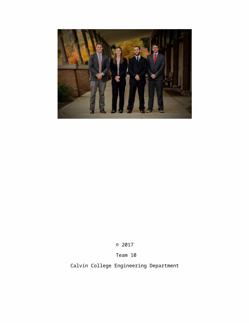
Tyson Butler, Brent Homan, Darbi Meyer, Derek VerMerris
11 December 2017
© 2017
Team 10
Calvin College Engineering Department
Executive Summary
Team 10, consisting of four mechanical engineering students, aims to design an aircraft capable
of vertical takeoff and landing (VTOL). In areas of limited take-off space, and with standard RC
aircraft technologies becoming outdated, the team hopes to renew the potential for technological
advancement with this product. The project incorporates vertical take-off, static flight, kinetic
flight, and vertical landing through an internal weight distribution mechanism. This provides
stability control with smooth weight transfer, while allowing for the flight of larger air crafts in
areas with restricted take off space. The project will be completed through Senior Design (ENGR
339/340) in the fall and spring semesters of 2017 and 2018.

Table of ContentsExecutive Summary.......................................................................................................................iii
Table of Figures..............................................................................................................................vi
Table of Tables..............................................................................................................................vii
Table of Equations........................................................................................................................viii
1. Introduction..............................................................................................................................1
2. Project Management.................................................................................................................4
2.1 Team Organization.................................................................................................................4
2.2 Schedule.................................................................................................................................4
2.3 Budget....................................................................................................................................4
2.4 Method of Approach..............................................................................................................4
3. Requirements............................................................................................................................6
4. Research...................................................................................................................................7
5. Task Specifications and Schedule............................................................................................8
6. Design.......................................................................................................................................9
6.1 Design Criteria.......................................................................................................................9
6.1.1 Design Norms..................................................................................................................9
6.1.2 Christian Perspective.......................................................................................................9
6.2 Design Alternatives..............................................................................................................10
6.2.1 Fuselage/Body...............................................................................................................10
6.2.2 Internal Stabilization/Weight Distribution Mechanism(s) (WDM)..............................11
6.2.3 Electrical Control System..............................................................................................12
6.2.4 Flight Control Mechanisms...........................................................................................13
6.3 Calculations..........................................................................................................................13
6.3.1 Thrust.............................................................................................................................13
6.3.2 Lift.................................................................................................................................14
6.3.3 Drag Forces...................................................................................................................14
6.3.4 FEA Air-Frame..............................................................................................................15
6.4 Design Decisions..................................................................................................................15
7. Testing....................................................................................................................................16
7.1 Internal Weight Distribution Mechanism Testing...............................................................16
7.2 Airframe Testing..................................................................................................................16
7.3 Electrical Component Testing..............................................................................................16
7.4 Stationary Testing...........................................................................................................17
7.5 Flight Testing.......................................................................................................................17
8. Conclusion..............................................................................................................................18
Acknowledgements........................................................................................................................19
References......................................................................................................................................20
Appendix A: Calculations..............................................................................................................21
Appendix A.1: Thrust Calculations...........................................................................................22
Appendix A.2: Lift Calculations................................................................................................23
Appendix A.3: Drag Force Calculations....................................................................................24
Appendix A.4: FEA Air-Frame.................................................................................................25
Appendix A.5: Weight Calculation............................................................................................26
Appendix A.6: Calculation References......................................................................................27
Appendix B: Components..............................................................................................................28
Appendix C: Flight Design References.........................................................................................29

Table of FiguresFigure 1: Lead Screw SolidWorks Design....................................................................................12
Figure 2: Belt and Carriage Prototype...........................................................................................12
Figure 3: Present Solidworks Prototype (Version VI)...................................................................25
Figure 4: Velocity Relationship Curve Graph...............................................................................27
Figure 5: Aircraft Controller..........................................................................................................28
Figure 6: Prototype of Slide and Carriage.....................................................................................28
Figure 7: Airfoil Design.................................................................................................................29
Figure 8: Airfoil Free Body Diagram............................................................................................29
Figure 9: Counter Rotating............................................................................................................30

Table of TablesTable 1: Weight Calculation..........................................................................................................26
Table 2: I.C.A.O. Standard Atmosphere Table.............................................................................27

Table of EquationsEquation 1......................................................................................................................................13
Equation 2......................................................................................................................................14
Equation 3......................................................................................................................................14
Equation 4......................................................................................................................................14

1. IntroductionThe development of a VTOL aircraft involves the design of a weight distribution mechanism,
systems control interface, and the optimization of a body design. This process will be completed
by Team 10 of the Calvin College Engineering Department's senior design class. The project
aims to create a working model of a small-scale aircraft that can alter between vertical and
horizontal flight via the shifting of an internal weight, and potentially other mechanical systems
to change wing orientation to assist in axial transfer. The internal mass will likely be shifted
using a lead screw or belt mechanism controlled by a small electric motor and other necessary
control systems. The propulsion of the aircraft will be supplied from two electric motors; one
mounted on the front crest of each wing.
The Team consists of four mechanical engineers: Tyson Butler, Brent Homan, Darbi Meyer, and
Derek VerMerris. Through the accumulation of wide variety of skills and backgrounds, Team 10
seeks to create a fully operational model that demonstrates our intellectual and practical strengths
as a team.
Tyson Butler was born and raised in
Littleton, a small town sitting directly west
of Denver, Colorado on the foothills of the
Rocky Mountains. From the time he was
very young, Tyson has pursued a diverse
array of passions including engineering,
biology, and the outdoors. After graduating
from Dakota Ridge High School in 2014
and receiving his International
Baccalaureate (IB) Diploma, Tyson found himself at Calvin College as a 2014 recruit for the
men's lacrosse team. It was Tyson's hope to discover a rigorous engineering education and a
genuine Christian community. During the Summer of 2015, Tyson began his first internship at
Biomass Controls in Putnam, Connecticut. After his experience with Biomass, Tyson offers
experience in 3D modeling, prototype fabrication, control system testing, coding and system
analysis. Presently, Tyson works as a design and testing engineer at Temper, Inc. During his time

at Temper, Biomass and Calvin college, Tyson has found a passion for research, design, and
development, and offers a variety of hands on, design based, and analytical experience.
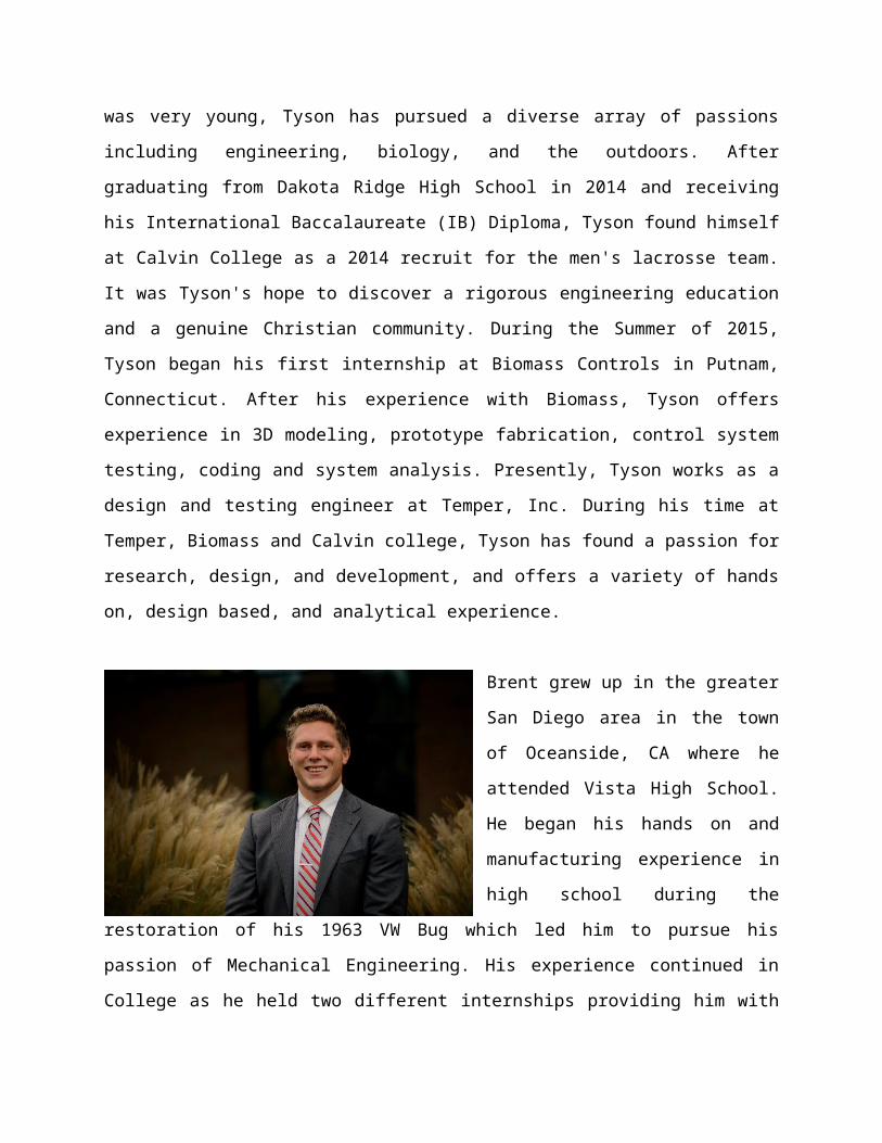
Brent grew up in the greater San Diego
area in the town of Oceanside, CA where
he attended Vista High School. He began
his hands on and manufacturing
experience in high school during the
restoration of his 1963 VW Bug which
led him to pursue his passion of
Mechanical Engineering. His experience
continued in College as he held two
different internships providing him with very valuable practical experience. The first internship
was at Best Metal Products in Grand Rapids, MI where Brent learned his first official
manufacturing experience as well as design and sales engineering for the company. Following
this experience, Brent went on to work for Highlight Industries in Wyoming, MI where he
assisted in assembly building robots and large stretch wrapping machines. Brent has also
obtained a sustainability designation during his time in the Calvin Engineering Program, and
seeks to use his knowledge of renewables and manufacturing work to contribute to the
completion of this project.
Darbi grew up in Granger, Indiana and
went to Penn High School. Her first
experience in engineering was at Calvin
College, but has always been interested
in how and why things work the way
they do. She spent the past two
summers interning at Cook Nuclear
Plant in Bridgman, Michigan. The first
summer was spent in Programs
Engineering looking at plant equipment qualifications and reliability. The second summer was
spent in Systems Engineering where she worked with the secondary systems of the plant in the
production of power. Darbi is also a part of the Calvin College Varsity Swim team.
Derek grew up in Dorr Michigan on
the family Friesian horse farm where
he encountered many different types of
agricultural machinery and many
mechanistic solutions to physical
problems presented in this world. His
desire to build machinery, tools, and
vehicles started very early in life and
was able to do so through the unique
opportunities given to him from living on a farm. For the past three summers Derek has interned
for Yanfeng Global Automotive Interiors as a product engineer and process innovation intern.
Derek would like to be a manufacturing engineer in the automotive industry upon graduation
looking and seeking greater efficiency in the manufacturing of automotive parts.

2. Project Management
2.1 Team OrganizationTeam 10, consisting of four senior mechanical engineering students, will be guided by Professor
Ned Neilson of the Calvin College Engineering Department. Tim Bangma, a design engineer at
Unist, also seeks to guide the team in their project, while serving as a sponsor for the team. Other
Calvin College engineering professors and faculty will also contribute to the progression of this
project through assistance in their areas of expertise.
2.2 ScheduleFor this project, the work has been broken down to a several fundamental deadlines over the
course of the year, and then some minor milestones that our team is aiming to achieve. Some of
the major scheduling objectives the team has set forth include the completion of research, initial
design decisions, and calculations by the end of first semester. Prototyping for the internal
weight distribution mechanism will be completed by the end of interim, and then completion of
building, prototyping, and testing of full aircraft will be completed during the spring semester. In
terms of immediate or small-scale milestones, the team typically meets once a week; at which
point these smaller tasks can be divided and accomplished.
2.3 BudgetThe budget for this project will stay below the $750 as allotted by the Calvin College
Engineering Department. This will be accomplished by using as many available parts as possible
through Calvin from past years’ projects. The budget will dictate what components will be
available to the team, and similarly, how many prototype designs can be created. The most
expensive pieces of equipment must be carefully managed to assure they are not broken during
testing. Darbi Meyer will oversee keeping track of the budget.
2.4 Method of ApproachTeam 10 has looked at different design alternatives for the aircraft as well as similar products
and the design of necessary components. Based on the capabilities and necessities of the aircraft
we are creating; we cannot follow the designs of other VTOL aircrafts on the market. Based on
this, our method of approach has been laid out in a few decision-making steps. The first decision

is the style of internal weight distribution mechanism that will be included in the aircraft. This
mechanism must be stable, lightweight, and be as space efficient as possible. This mechanism
and the decisions made can be seen in the decision section of the report. Once this mechanism
has been designed, created and tested, the design of the plane body can then undergo
construction. The reason that the mechanism must be designed before the body of the plane is
that this mechanism will provide our team with the majority of our weight and space constraints
which will then dictate the size and capacity of the overall aircraft. As specified, the VTOL
aircraft will be capable of vertical takeoff, static flight, kinetic flight, vertical landing, and then
also sustained flight during the transition from static to kinetic flight.

3. RequirementsThe aircraft will be engineered to operate in moderate wind conditions as it is rare for RC
enthusiasts to encounter a windless day. The aircraft will also be maneuverable in vertical take-
off and landing trajectories. Some conventional aircrafts have the ability to hang from there prop
in the air and as a result could potentially land vertically if it had the right landing gear however,
it takes many years of skill to achieve this type of flying ability and is a rare ability amongst
enthusiasts. The requirement for this VTOL aircraft will be that with little skill a new flyer will
be able to easily take-off and land the aircraft without it crashing. A self-set requirement of five
minutes of fly time will be the minimum and it will be our goal to achieve a greater length of fly
time before the battery is depleted. The end user will also be able to disassemble the aircraft into
key components for transportation, maintenance, as well as replacement of parts in the event of a
crash. The aircraft will be ergonomic and safe to use, as it is our goal to have a product that
instils confidences in the end user's flying abilities. The product will not cost more than $750
dollars to make as a prototype and will be competitive with the current products already on the
market for price and performance. The aircraft will be propelled by two electric motors powered
by a lithium ion battery. This aircraft is to leverage the use of components already existing on the
market to achieve a new type of take-off and landing recently only reserved for helicopters.

4. ResearchThere are many aspects of aeronautical engineering Team 10 was not familiar with, so research
began with the basics and advanced from there [1]. One focus of the team was finding other
products on the market currently that matched the capabilities of our aircraft or were similar in
design. This was achieved through the use of several google searches as well as exploration
through the websites of some companies. Two products, the Convergence VTOL PNP [2] and X-
vert VTOL BNF Basic [3], were found, but both products still differed greatly from the design
envisioned by Team 10. Research then focused on the components needed for the completion of
the aircraft as well as the overall weight and cost. Knowing weight would be one of the biggest
factors of the design, and it was important to get a starting estimate for feasibility calculations.
To potentially save cost of components, part inventory research was done by looking through
past senior design projects for useable components. Patent research also proved to be helpful by
demonstrating that shifting weight can in fact change the flight pattern of a small RC aircraft.
One interesting patent was for a small quad-copter, which is not the design Team 10 intends, but
it uses four adjustable weights on a track, similar to one design alternative the team has
considered, to control the flight of the aircraft [4]. Initial feasibility calculations including lift,
thrust, and drag have been done with the aid of online research, such as tutorial pages offered by
NASA’s Glenn Research Center [5] [6], and textbooks including Fundamentals of Thermal-
Fluid Sciences [7]. Research will continue throughout the remainder of the project to insure
successful flight.

5. Task Specifications and ScheduleFor the completion of the task of creating a vertical take-off and landing aircraft, the design and
construction must be broken into sections and steps. The first step of this project is the design of
the weight distribution mechanism. By creating the design of this aspect first, our team will be
able to better assess the complexity of this project, as well as the size constraints that we are
dealing with. Creating a working model is going to involve fine tuning of the relationship
between power output and weight, and this can be better analyzed once the overall size capability
is known. This design phase is expected to take about two or three weeks.
Once the design of the internal mechanism has been created, the design of the body of the plane
can be created based on the size constraints set. This design will begin as rough estimates, and
then become more precise through the process of prototyping which will allow our team to find
the most effective style. Implementing the internal mechanism and the motors will occur after
prototyping and testing has been conducted for the body of the plane. This design and
prototyping process is expected to take one month.
After the finalization of a body design prototype, the internal mechanism can be fabricated and
then installed onto the plane. Completion of this task will then allow for flight testing of the
aircraft followed by the installation of the motors and the wiring and coding of the system. This
process is expected to last about a month and a half.
With the assembly of the aircraft now completed, the focus of the team will then turn to testing
and improvements for flight and fluidity. The task of this project is to design an aircraft that can
sustain static and kinetic flight with the capability of vertical take-off and landing. Once a
working model has been created, the task is complete, but as Calvin Engineering Students, our
team seeks to base our project on trust, and transparency which will lead us to continue to
improve the model until we feel it is the best representation of our work that we can deliver.

6. Design
6.1 Design CriteriaBased on the specific capabilities required for this project, our team used different design criteria
than what would be used for a traditional aircraft. One of the biggest criterion that we have
considered in our design has been weight. With the complex mechanism integrated within our
aircraft, we have to be careful in order to keep the weight at a point where the aircraft will still be
able to fly. This has been a major influence in not only our component selection, but also in our
design decisions. In addition to the weight constraints we are facing, our team also has a limited
budget which influences our design decisions as well. With this financial constraint, our team
must weigh the importance of certain components and then spend money accordingly. In relation
to a traditional aircraft, our aircraft involves many differing capabilities including an altered
body style that supports this vertical flight. The criteria listed above has influenced our decision
process and led to the current design that is implemented in the prototyping process.
6.1.1 Design Norms
While all the design norms discussed in this course are important when looking at this project,
our team has chosen three of them to focus on specifically: Trust, Transparency, and
Integrity. Through our education at Calvin College, we have learned the importance of
integration of faith and engineering. As a team, we ensure that our mentors and customers can
trust that our project has the capabilities we claim it to have. In addition to that, our team seeks
to maintain trust in each other and the aspects of the project we are working on individually. In
addition to that, our team also seeks to work with transparency throughout the entirety of this
project. This will look like a consistently updated website where our mentors and potential
customers will have the ability to track our progress. Our designs and design decisions should be
something that those interested in our project should be able to keep up with and track. Finally,
we also commit to integrity through the construction and design of this project. Our final project
will not be something different than we are claiming it to be, and this will be achieved through
the trust and transparency already established.

6.1.2 Christian Perspective
For this project, our team has chosen a guiding verse that we are going to remember and think
about for the entirely of this project. The verse is Romans 12:4-6,
For as in one body, we have many members, and each member does not serve the same
function. So we, though many, are one body in Christ, individually made one of another,
having gifts that differ according to the Grace given to us.
This verse talks about the different gifts that we all have as Christians, and that none of these
gifts are greater than any other gift. Each gift is important in its own way, and contributes
equally to the Kingdom of God. Through the following of this verse, our team is able to
recognize the different, and equally important, gifts and strengths that each of us bring to the
table, and how this diversity of strengths is what will allow us to complete this project.
6.2 Design AlternativesThe design of a VTOL aircraft can be considered in terms of four main mechanisms/sections: the
fuselage or body, the internal stabilization/weight distribution mechanism(s), electrical control
systems, and flight control mechanisms.
6.2.1 Fuselage/Body
The design of the fuselage, or body, of a VTOL aircraft must incorporate considerations of
weight, lift, balance (center of gravity), and spatial considerations for internal electrical
components and necessary internal stabilization/weight distribution mechanism(s). As an initial
approach, materials for the construction of the body are to be determined with the goal of
maximizing the structural integrity of the plane and minimizing weight. It is anticipated that final
fabrications of the body will be completed using an available mill on campus from Solidworks
design files. With this approach, it is necessary to be able to mill the selected body material(s).
With this consideration, the body of the plane will be constructed in sections and manually
assembled to accommodate the milling process. The final design of the body will be determined
after the specified testing period. Multiple prototypes will be constructed by hand and using a
mill for testing and design optimization.
The fuselage of the plane will be responsible for housing electrical components and the weight
distribution mechanism. Electrical components will be responsible for controlling exterior

mechanism (ailerons and elevators), internal mechanisms (motors and switches), supplying
power, regulating power, and receiving controller signals. All electrical components (excluding
exterior components and those in the weight distribution system) will be housed near the nose of
the fuselage. Behind the electrical control system, the weight distribution mechanism (WDM)
will run axially along the length of the fuselage. The size and operation requirements of the
WDM will be determined after several phases of testing.
The largest consideration for the design of the whole aircraft is the shape, form and scale of the
wings and tailfins. The surface area must be large enough to accommodate the general size of
other components via generated lift. As there is a linear relationship between lift and surface
area, wings will be optimized through testing and further analysis with regard to weight, scale,
motor placement, and other aerodynamic criteria as seen fit. Numerous types of traditional
airfoils were considered as well; with desire for maximum lift and low drag forces. As seen in
Figure 7 of Appendix C, multiple airfoil designs were considered. As the plane will most likely
operate at moderate speeds (<10mph on average), it is necessary for the airfoil design to
incorporate considerations for maximized lift, as well as a generally symmetric design to prevent
any non-symmetric forces during vertical flight. With these considerations, it is likely that the
wings will be generally symmetric; as a combination of a GA(W)-1 and Symmetric Airfoil
(Appendix C Figure 7).
With the overall hope of developing a sleek and aerobatic wing profile, an additional objective is
to maximize aerodynamic stability and responsiveness to RC signals from the flyer. To achieve
this goal, there is an opportunity to design folding wing tips; permanently or manually (using an
RC controller). Folding the wing tips will increase overall stability as an air stream passing
toward the wing tips will be directed upward along the bottom of the wing. More importantly,
reorienting the wing tips from a parallel position with the overall wing to a folded position
during transitions in flight mode changes the points of thrust across the plane. Ultimately, raising
the points of thrust (motors at wing tips) should result in a natural forward/rearward rotation of
the planes body; in conjunction with the WDM.

6.2.2 Internal Stabilization/Weight Distribution Mechanism(s) (WDM)The main objective of the WDM is to vary the center of gravity with respect to systems of
propulsion, such that the plane has the ability to transfer to and from a static/vertical flight mode
to one that is kinetic. Ultimately, to achieve necessary weight distribution the battery will take
the place of an additional mass, and will be transferred axially along the body of the plane. The
WDM will be designed with a focus on smooth/steady weight distribution, weight minimization,
and in-flight responsiveness with regard to WDM operation.
It is anticipated that a lead-screw or belt and carriage mechanism will be constructed. The lead
screw rotates to transfer a mounted harness that harbors the battery. The lead screw will be
driven by a motor with internal controls to regulate the speed and stability of weight distribution.
This design can be seen in its initial design phases in Figure 1 below. The belt and carriage
design would transfer the weight along a track, with the battery attached to the carriage. The
motor to drive the belt could potentially be attached to the carriage as well. This design can be
seen as the first 3D printed prototype in Figure 2 below.
Figure 1: Lead Screw SolidWorks Design
Figure 2: Belt and Carriage Prototype

6.2.3 Electrical Control SystemThe basis of the aircrafts control system will incorporate a standard radio control system with
specific variations for the WDM. "Standard" implies a system that would be expected on most
radio control planes, generally consisting of a battery to power system components, a receiver to
transfer radio signals to necessary components, a controller to output user operations, motors for
propulsion, servos to control ailerons and stabilizers, and additional components for power
regulation. The key variation of the VTOL's control system includes the addition of an internal
WDM and the addition of a motor (compared to 1) and two elevators. Additional components,
specifically the WDM, may require coding and the addition of a control device compatible other
controls and the user's receiver. Specific electrical components are still to be determined.
6.2.4 Flight Control MechanismsTo achieve static and kinetic flight modes, that are also characterized to be fluid, responsive and
stable, it is necessary to develop an adequate flight control system. General flight control
mechanisms consist of the motors (and propellers), servos, elevators, and the internal WDM. To
achieve static and kinetic flight, a flight control system including four elevators (four tail fins and
four servos) and two motors has been outlined as a potential solution. The use of four tail fins
will allow for stable variations in yaw while in static and kinetic flight modes, as well as the
combination of pitch yaw and roll. The addition of two motors instead of one will allow for
stabilization in the separation of propulsion mechanisms, as well as the potential for an addition
plane of motion while in static mode parallel to the belly of the aircraft; otherwise, the
introduction of a horizontal plane of motion.
6.3 Calculations
6.3.1 ThrustThe very first calculation that was addressed was that of thrust, the very success of this project is
dependent on the aircraft having the ability to accelerate upwards in a vertical trajectory in a
manner that not only overcomes the force of gravity but also moves enough air over the wings to
create lift. Online resources where used to attain the appropriate equations used to calculate lift
in the context of specific pitched props at a set rotational speed. The equation seen below takes
into account Euler's Law, the rotational speed of the prop, the diameter and pitch of the prop, and
the surface area of the prop.

Thrust Force=4.39 x10⁻⁸ RPM D3.5
√ pitch(0.00042 RPM pitch−V 0)
Equation 1
6.3.2 LiftIn addition to the other preliminary calculations performed for the Vertigo VTOL aircraft, we
have also measured the aircraft’s lift capabilities from the following equation acquired from
NASA,
L=12
ρ V 2 A CL
Equation 2
In this equation, “L” represents the lift, which must equal the airplane’s weight in pounds. Rho is
the density of air, and this will change due to altitude. These values can be found in Table 2:
I.C.A.O. Standard Atmosphere Table located in Appendix A.5. The velocity of the aircraft
expressed in terms of meters per second is shown in the term “V,” and “A” is the wing area of
the aircraft in square meters. The Coefficient of Lift (CL), is determined by the type of airfoil
and angle of attack, and can be found using Figure 4: Velocity Relationship Curve Graph in
Appendix A.5.
6.3.3 Drag ForcesDrag calculations were also completed to verify the aircraft would not experience too much
resistive force to fly. These equations were found from NASA’s Glenn Research Center online
resource. The following equation describes the drag force experienced by the aircraft.
D=12
Cd ρ V 2 A
Equation 3
Variables of ρ, V, and A represent density of air, velocity, and reference area as in the Lift
Calculations. “D” is the force of drag on the aircraft and Cdis the drag coefficient. The drag
coefficient consists of two parts, the basic drag and induced drag. The basic drag is resistance on
the aircraft due to its shape and material. The induced drag is the resistance experienced due to
lift on the wings creating a pressure differential.
Cd=Cdo+Cdi
Equation 4
The overall drag coefficient is the addition of these two drag forces seen in the equation below
with Cdo being basic drag and Cdi as induced drag. These calculations can be seen in Appendix
A.3.
6.3.4 FEA Air-FrameA Finite Element Analysis (FEA) model is currently in progress using Solidworks to determine
airflow properties for present prototype designs. Using prototype Solidworks designs (Figure 3),
the Flow-Analysis Simulator in Solidworks will be used to get rough estimates for mass, surface
area, lift, drag, and other resulting forces expected during both kinetic and static flight modes.
Results will be taken into consideration to optimize designs for minimal weight, maximum lift
and stability, and maneuverability.
6.4 Design DecisionsThe two biggest decision factors of the design are weight and cost. The aircraft will not be able
to get off the ground if it weights too much, and the team is working with a limited budget.
Components will be selected based on these two decision factors first. With most things related
to engineering, more costly components are usually lighter, stronger and have a greater
performance delta in comparison. We will be using micro high torque precision servos for their
lightweight and high strength, brushless 1100kpv motors for their instantaneous torque and great
power to weigh ratio compared to traditional brushed motors. Lithium Polymer batteries are
more expensive option to Ni-Cad batteries but have a better capacity of power in respects to

weight and we need to shave as many grams as possible. A twin-engine prop setup will be used
as it will yield the most lateral maneuverability as well as stability.

7. TestingTesting will be crucial for the successful flight of the aircraft. One of the biggest concerns and
places for failure is crashing. This may result in going over budget and time to fix and replace
broken components. For this reason, intermediate testing will be done throughout the prototyping
stage before final flight tests are conducted. All mechanical components will be modeled and
FEA tested in Solidworks.
7.1 Internal Weight Distribution Mechanism TestingTesting has begun on the internal weight distribution mechanism. Solidworks drawings of a
carriage and track have been created for the belt and carriage weight transfer system. These
components have been 3D printed to test the maneuverability of the mechanism. A leadscrew
and carriage design has also been modeled in Solidworks and a larger component has been
acquired for conceptualizing purposes. Once coding for the two design options for the weight
distribution mechanism is complete, the two designs will be tested for easy of movement, time to
transfer, and use of space.
7.2 Airframe TestingInitial designs for the body of the aircraft have also been designed in Solidworks. These designs
have been tested with FEA for structural and aerodynamic design. Two-dimensional foam
prototypes have been created and tested for lift capabilities based on aerodynamics. Initial
designs have also been created out of foam by use of a table top CNC router to test the
capabilities of the mill and response to design input. Further testing of the airframe will include
strength testing of the airframe material and coating options. The final material will be selected
based on strength and weight.
7.3 Electrical Component TestingTesting of electrical components will happen simultaneously with prototyping. All parts will be
tested before implementation to insure they function properly as well as after they have been
included into the system to verify correct wiring. All components need to function properly
before being enclosed in the airframe. The range of the receiver will be tested by validating the
signal at greater and greater distances. This will be done outside on Calvin’s Common’s Lawn or
Gainey Athletic Facility.

7.4 Stationary Testing Stationary testing must be conducted before any flight test can take place. All electrical
components must respond as expected by the controller as well as the weight distribution
mechanism. The weight distribution mechanism will be tested to confirm it moves to the correct
spot and transitions the center of gravity of the aircraft properly. The battery life will also be
tested to insure it will not die mid-flight. This will be done using a multimeter, being careful to
not accidently short the battery. Along with aircraft stationary testing, flight simulation testing
will be practiced so the flier of the plane is prepared for flight testing. This will be done using a
program called RealFlight that allows computer based simulation of RC flight.
7.5 Flight Testing Once all ground testing is done, flight testing can begin. With a limited budget and time frame,
flight testing must be done extremely cautiously to make sure the plane does not crash and
completely break. Initial flight testing will include vertical takeoff and limited hovering or static
flight. This must be successful before moving on to transitioning to horizontal flight and vertical
landing. Video will be taken of all flight tests to watch for areas for improvement.

8. ConclusionIn conclusion, it is Team 10's main objective to complete all outlined tasks to meet all design
norms; specifically, transparency, trust, and integrity. While it is anticipated that there will be
variations in specified designs and methods in the completion of a working prototype, it is
believed that a weight distribution mechanism(s) can be successfully applied to achieve a fully
function VTOL aircraft. Through accurate testing, Solidworks modeling, and thorough design
methods, it is possible not only to meet all specified objectives, but to complete all tasks in a
timely manner.

Acknowledgements
Calvin College Engineering Department, for sponsoring the project
Tim Bangma at Unist, for mentoring our team for the project
Chuck Boelkins the owner of Unist for sponsoring the project
Professor Neilson, for advising the team throughout the project
David Malone, for assisting the team in library research

References[1] Weitz, Paul J. “A Qualitative Discussion of the Stability and Control of VTOL Aircraft
During Hovering (Out of Ground Effect) and Transition.” DTIC Online, Defense Technical Information Center, 1964, www.dtic.mil/docs/citations/AD0622205
[2] “Convergence VTOL PNP.” HorizonHobby, <www.horizonhobby.com/EFL11075?KPID=EFL11075&CAWELAID=320011980001297380&CAGPSPN=pla&CAAGID=37619207031&CATCI=pla-382671762385&gclid=EAIaIQobChMIyK2BnsaA2AIVybrACh1cFQG-EAQYASABEgKf1_D_BwE>
[3] “X-VERT VTOL BNF Basic.” Horizon Hobby, <www.horizonhobby.com/EFL1850?KPID=EFL1850&CAWELAID=320011980001297786&CAGPSPN=pla&CAAGID=37619207031&CATCI=pla-272081934850&gclid=EAIaIQobChMIyK2BnsaA2AIVybrACh1cFQG-EAQYAiABEgJFBfD_BwE>
[4] Vaughn, Brad Lee. Adjustable Weight Distribution for Drone. 18 Oct. 2016.
[5] “The Drag Equation.” NASA, The Glenn Research Center, 5 May 2015, <www.grc.nasa.gov/www/k-12/airplane/drageq.html>
[6] “The Drag Coefficient.” NASA, The Glenn Research Center, 5 May 2015, <www.grc.nasa.gov/www/k-12/airplane/drageq.html>
[7] Cengel, Yunus A., et al. “Chapter 15.” Fundamentals of Thermal Fluid Sciences, 5th ed.,
McGraw-Hill Education / Asia, 2017.
[8] NASA, NASA, www.grc.nasa.gov/www/k-12/WindTunnel/Activities/lift_formula.html.
[9] “Conventional Airfoils and Laminar Flow Airfoils.” Wing Design, Aviation Publishers, 2
May 2008, www.allstar.fiu.edu/aero/wing31.htm.
[10] “Romans 12.” The Holy Bible: Containing the Old and New Testaments, Oxford University Press, 2002.
-
Appendix A: Calculations

Appendix A.1: Thrust Calculations

Appendix A.2: Lift Calculations

Appendix A.3: Drag Force Calculations

Appendix A.4: FEA Air-Frame
Figure 3: Present Solidworks Prototype (Version VI)
Appendix A.5: Weight Calculation
Table 1: Weight Calculation

Appendix A.6: Calculation References
Table 2: I.C.A.O. Standard Atmosphere Table
Figure 4: Velocity Relationship Curve Graph

Appendix B: Components
Figure 6: Prototype of Slide and Carriage
Figure 5: Aircraft Controller

Appendix C: Flight Design References
Figure 7: Airfoil Design
Figure 8: Airfoil Free Body Diagram

Figure 9: Counter Rotating