executive summary - researchspace - csir
TRANSCRIPT

Safety in Mines Research Advisory Committee
Literature survey on the advance
detection of dykes in underground coal
mine workings
Prof. G A Fourie
Laboratory for Advanced Engineering
University of Pretoria
Project COL 503b
October 1998
i
Executive Summary
To minimise risk, a more effective system of mine planning and operation is required
which calls for advance knowledge of structural and geological conditions ahead of
the coal working face. This research project attempts to identify, by means of a
literature survey, different exploration and geophysical methods that could be used
to detect dykes ahead of underground coal mine workings.
In this study a range of geophysical and exploration methods have been identified
which are generally used in the mining industry. Each different method exploits a
different physical property of the earth’s crust, e.g. seismic and acoustic methods
measure the velocities of sound waves, while magnetic methods distinguish the
variance in magnetic susceptibility of different rock types. Gravitational survey
methods detect and measure lateral variations in the earth’s gravitational pull that
are associated with near surface changes in density.
Dykes generally display a high level of magnetic susceptibility and magnetic survey
methods are therefore commonly used by most coal mining companies to identify
the presence of this geological feature. The sophistication of aeromagnetic survey
techniques has increased significantly over the past decade and is now routinely
used by local and overseas coal mining companies to explore relatively large target
areas fairly successfully.
Horizontal, in-seam drilling was first tested in the United States during the late
1950’s. This technique was initially developed to degasify the coal seam ahead of
mining operations. Similar trials were conducted in Australia during 1980 and by
mid-1981 the Australlian Coal Industries Research Laboratories Limited (ACIRL)
reported that “600 m longholes can be achieved on a regular basis”. In-seam drilling
is now practiced on a number of South African collieries and hole lengths of up to
1200 m are standard. During the early 1990’s Amcoal introduced incline-directional
drilling from surface as a means to detect dykes and other geological features ahead
of mining. Average borehole lengths achieved with this method are now in

ii
the order of 1200 metres, however, development work is in progress to increase the
effective reach to 2000 metres. Similar work is currently in progress at Sasol Coal.
The use of ground penetrating radar as a means to detect dykes has been tested on
various South African gold mines. Initial reports indicate that the presence of dykes
and faults could be detected successfully up to a distance of 40 metres ahead of
the mining face. The same level of success could, however, not be achieved on coal
mines.
At present most South African coal operations use a combination of vertical drilling,
aeromagnetic surveying and in-seam drilling techniques to detect and identify the
presence of dykes ahead of the mining face with a relative high degree of accuracy

iii
Acknowledgements
The author is indebted to the following persons for help received and for their
valuable contributions in preparing this report :
- Mrs. G. Ehlers, Information Specialist, University of Pretoria, for assisting
with the search and collection of relevant publications, locally and abroad,
- Prof. W.J. Botha, Department of Geophysics, University of Pretoria, for
technical advise.
-Mr. S.R. Mc Mullan, Poseidon Geophysics, and Mr. Martin Frere, Geodass,
for their contribution on Magnetic Survey techniques used in Southern Africa.
Contents
iv
Page no.
1 Introduction 1
2. Investigation objectives 4
3. Seismic and acoustic methods 5
3.1. Background 5
3.2. Basic principles and concepts
of shallow seismic reflection profiling 5
3.3. In-seam seismic methods 9
3.4. Hole-to-surface seismic methods 11
3.5. Typical applications 13
3.6. Reference list 14
4. Tomography 18
4.1. Introduction 18
4.2. Applications in mining 20
4.3. Reference list 21
5. Ground-penetrating Radar 23
5.1. Electromagnetic methods 23
5.2. Application in mining 24
5.3. Reference list 27
6. Radio Imaging Method 30
6.1. Principles 30
6.2. RIM operations 31
6.3. RIM survey results 32
6.4. Application in detecting dykes ahead of mining 32
6.5. Reference list 32
7. Drilling 33
7.1. Vertical or near vertical drilling 33

v
7.2. Horizontal or in-seam drilling 33
7.3. Developments in South Africa 37
7.4. Reference list 38
8. Magnetic Methods 40
8.1. Magnetic susceptibility 40
8.2. Magnetic method theory 41
8.3. Magnetic survey techniques 41
8.4. Instrumentation and survey methods 42
8.5. Application in mining 43
8.6. Reference list 44
9. Gravitational method 47
9.1. Fundamental principles of gravity prospecting 47
9.2. Equipment 48
9.3. Application in coal mining 48
9.4. Reference list 49
10. Conclusions 51

1
1. Introduction
This review examines the various techniques of applied geophysics used by the
coal industry at large to delineate the boundaries of geological and man-made
structures in coal deposits, with special reference to the detection of dykes ahead
of underground workings.
Applied geophysical techniques exploit the physical properties of the earth to
investigate relatively small-scale and shallow features in the earth’s crust. They
have been used for several decades in the exploration for metallic minerals and
since the beginning of this century in the exploration for oil and gas and were first
applied to coal deposits in the 1920s and 1930s
Although geophysical techniques continued to be used to some extent,
examination of coal deposits in many areas continued until the early 1970s to be
performed mainly by a combination of geological mapping and the drilling of
boreholes. The coal industries in many countries have become aware of the
potential economic and safety benefits which may be gained from the use of
applied geophysical techniques to examine coal deposits for features of
importance to mine planning and operations.
Geophysical techniques are capable not only of delineating the edges of the coal
seam more accurately than by using surface mapping, but also of locating and
characterising geologic and man-made structures in the deposit. The commonest
geologic structures are faults, folds, dykes and clay layers which may cause the
coal seam being mined to decrease in thickness or even to disappear altogether.
In addition, they may cause roof falls, accumulations of gases and water, all of
which contribute to the risk associated with mining. Features such as these can
rarely be detected by only drilling conventional vertical exploration boreholes.
Clearly if the coal industry could plan its operations to avoid such structures then it
might be able to reduce losses of coal, disruptions to production and most
important, the reduction of safety hazards. A number of geophysical techniques
originally developed in the search for metallic minerals, oil or gas have been
tested in coal deposits. Each technique responds to a certain physical property of

2
the rocks. The objective of this project is to determine, through a literature survey,
various
geophysical and other techniques used in the coal industry to detect the presence
of dykes ahead of underground mining.
There are a number of reasons why geophysical techniques are not used more
widely in the coal industry. One which may be the cost involved or otherwise the
prejudice against geophysical techniques due to earlier poor results in surveys.
Often, the poor results have been due to communication problems between
mining companies and the geophysical companies in terms of the needs of the
one and the capabilities of the other. Clarke (1976 a,b) and Ziolkowski (1981)
discuss some of the difficulties encountered in the United Kingdom in the early
1960s when surface seismic surveys were first performed. Price (1978) surveys
the geophysical techniques employed in the Australian coal industry and the
confidence placed in them by the mining companies. The clash of attitudes
between the enthusiastic geophysicists and the sceptical mining companies which
is noted is certainly not unique to Australia.
However, confidence in the techniques has steadily grown as more and more
successes are recorded. Many of these may be attributed to the redesign of field
procedures and instrumentation specifically for coal rather than their adoption
from oil and gas exploration techniques.
Reference list
Clarke, A.M. 1976a. Seismic surveying and mine planning : their relationships and
application. In : Coal Exploration. W.L.G. Muir (ed) Proceedings of the 1st
international coal exploration symposium, London, UK, 18-21 May 1976. San
Francisco USA, Miller-Freeman, p 158-191 (1976)
Clark, A.M. 1976b. Why modern exploration has little to do with geology and much
more to do with mining. Colliery Guardian, 224 (8), 323-336. August 1976.
3
Price, G.P. 1978. A survey into the application of geophysics in the Australian coal
mining industry. Mount Waverley, Australia, Commonwealth Scientific and Industrial
Research Organisation, June 1978
Ziolkowski, A. 1981. Seismic surveying in British coalfields. The Mining Engineer,
140 (234) : March 1981.
2. Investigation Objectives
A major component of mining risk is the risk of encountering unexpected
geological disturbances ahead of the working face. Of particular concern to the

4
coal mining industry is the presence of dykes in underground workings and the
general safety risks associated there with.
The objectives of this study are to determine through a literature search, various
methods that can be used to determine the presence of dykes ahead of mining
and to identify further research work (if any) that needs to be performed.
3. Seismic and acoustic methods
3.1. Background

5
Seismic surveying techniques from the surface of the earth were originally
developed by the oil and gas industry in the search for large geological structures
containing hydrocarbons at depths of 600 to 10 000 metres(Bredewout and
Goulty, 1986). Recent developments associated with the use of the seismic and
acoustic methods to evaluate environmental sites have enhanced the potential of
this technique for cost-effective application in the mining industry (Miller and
Steeples 1990, 1995). Shallow, high-resolution seismic reflection profiles can be
useful in characterising shallow structures or anomalies and extending features
identifiable in outcrop and surface excavation into the upper several hundred
metres of the subsurface (Miller and Steeples 1995). The high-resolution seismic
reflection method has only recently developed into a practical and effective tool
for identifying shallow (<100 metres) structures (Miller and Steeples, 1995;
Hunter et al., 1985; Jongerius and Helbig, 1988 ; Treadway et al., 1988; Miller et
al., 1989; Miller and Steeples, 1991; Goforth and Hayward, 1992).
3.2. Basic principles and concepts of shallow seismic reflection profiling
Seismic methods make use of the fact that elastic waves travel at different
velocities in different rocks and behave in certain ways when encountering
interfaces between different rock types. Steeples and Miller (1993) refer to these
velocity differences as “acoustic impedance contrasts”. Accoustic impedance
contrasts occur at natural boundaries between geologic layers, although
manmade boundaries, such as tunnels and other underground excavations, also
represent contrasts. The classic use of seismic reflection is to identify the
boundaries of layered geologic units. However, the technique can also be used
to search for localised anomalies such as sand/clay lenses and cavities.
Compression waves (P-waves) propagating through the earth behave similarly to
sound waves propagating in air. When sound waves (voices, explosions, horns,
etc.) come in contact with a wall, cliff or building (all acoustic contrasts), it is
common to hear an echo. When a P-wave comes in contact with an acoustical
contrast underground, echoes (reflections) are also generated. P-wave

6
reflections can be thought of as sound echoes from underground acoustic
impedance contrasts. In the underground environment the situation is more
complex because some P-wave energy impinging on a solid acoustical interface
can also be transmitted across the interface, refracted at the interface and/or
converted to other types of seismic waves at the interface.
Seismic methods are sensitive to the physical properties of earth materials and
relatively insensitive to the chemical make-up of contained fluids in earth
materials. The work of Hunter and Pullan and their colleagues at the Geological
Survey of Canada (Hunter, et al 1984; Pullan and Hunter, 1985) and Helbig
(Doornenbal and Helbig, 1988 Jongerius and Helbig, 1988) and his students at
the University of Utrecht in The Netherlands has been instrumental in developing
shallow seismic reflection techniques. In particular, the simple data manipulation
and display of Hunter’s optimum window-common offset makes it a cost-effective
method of imaging the shallow subsurface in areas conducive to seismic
reflection.
The simplest case of seismic reflection is a single layer over an infinitely thick
medium (Figure 1). Seismic energy induced into the ground from a point is
radiated spherical away from that point in much the same fashion in three
dimensions as waves from a pebble tossed into a still pond radiate outward in
two dimensions (Steeples and Miller, 1993). One particular ray path will direct
energy to a subsurface layer and return as an echo to the ground surface first.

7
Figure 1
BASIC PRINCIPLES OF SEISMIC SURVEY METHOD
(After Steeples and Miller, 1993)

8
Seismic reflection surveys routinely involve three basic parts : acquisition,
processing and interpretation. A variety of selectable parameters and methods
are possible at each of these three distinct stages. Pronounced differences exist
between shallow and conventional seismic reflection techniques during the
acquisition and processing stages. The basic principle of interpretation for
shallow and conventional seismic reflection is consistent, except for scale
differences. The underlying theoretical method is consistent for conventional and
shallow applications.
i) Data Acquisition
The most site-dependent part of the acquisition system is the acoustic energy
source. A variety of sources have been developed and are in routine use on
shallow seismic reflection projects. As a human voice is a source of acoustic
energy, so is an explosion, a car horn or an electric razor. The method of
generating and transmitting acoustic energy into the ground is what determines
the quality of a source at any particular site.
There are two types of sources : impulsive and vibratory. Impulsive sources are
the predominant type of shallow seismic source while vibratory sources are the
predominant conventional seismic source. The frequency-limited nature of
vibratory sources is what has held them to very limited used on shallow reflection
surveys. Most shallow refection surveys employ weight drop (accelerated) or
explosives as the source of acoustic energy. Other types of sources which may
be used are weights, hydraulic hammers, vibrators, air guns, gas exploders and
piezoelectric stacks (Lepper and Ruskey, 1976; Zoilkowski 1978; Zoilkowski and
Lerwill, 1979).
The second part of the acquisition system consists of seismic detectors. The
main requirement of the seismic wave detectors is that their frequency response
should match the frequencies transmitted through the rocks by the seismic
source. The commonest detectors in use are geophones and hydrophones with
natural frequencies of 28Hz and 100Hz (Farr and Peace 1979).

9
ii) Data Processing
All data, generated by the geophones, are processed using special developed
computer programmes. In general, the aim of the computer processing of raw
seismic data is to enhance the signals from features of interest and to reduce
unwanted noise to a minimum. “Noise” in this case does not only mean the
effects of ground roll and man-made phenomena but also the distortion of the
seismic data by velocity variations in the rocks and differences in elevation over
the survey area. The results of processing the digital data is normally a seismic
record or seismogram (Ziolkowski and Lerwill, 1979; Steeples and Miller, 1993).
iii) Data Interpretation
Interpretation of the collected seismic data needs a thorough understanding of
the geology of the project, seismic methods used and other relevant information.
3.3. In- seam seismic methods
A variation to normal seismic surveying techniques is underground - or in-seam
seismic surveys.
Most of the surveys currently being conducted underground involve the use of
channel waves propagating in the coal seam to detect discontinuities in advance
of mining although some more conventional seismic surveys have been done
from mine roadways downwards into the underlying rocks.
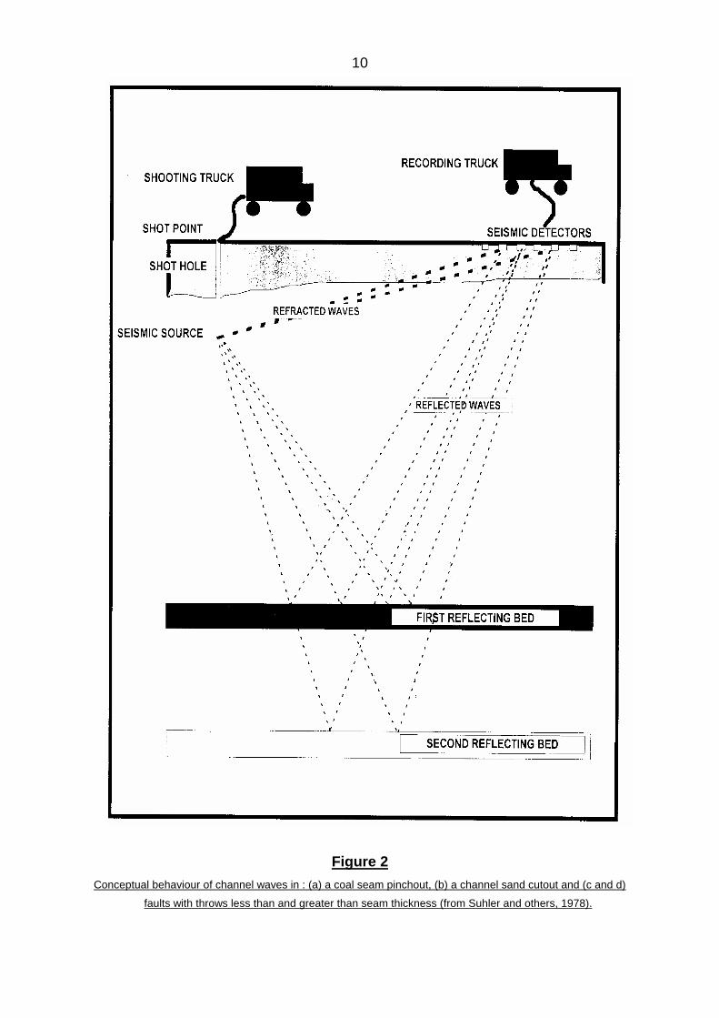
In the in-seam seismology work two techniques are used in the detection of
discontinuities in the coal seam: transmission in which the distortion of the
channel waves as they pass a disturbance is recorded and reflection in which the
reflected waves are recorded. Suhler and others (1978) present sketches
illustrating the conceptual behaviour of channel waves reflected from or
transmitted through certain geological discontinuities and anomalies (Refer to
Figure 2)
10
Figure 2
Conceptual behaviour of channel waves in : (a) a coal seam pinchout, (b) a channel sand cutout and (c and d)
faults with throws less than and greater than seam thickness (from Suhler and others, 1978).

11
The equipment used for this in-seam seismic surveys is similar to that used in
surface seismic work. Rüter and Schepers (1979) describe equipment used in the
Federal Republic of Germany : the United Kingdom equipment is described by
Dawson et al (1994) and Jackson (1985)
The seismic sources used underground are usually small quantities of approved
commercial explosives placed in drill holes 2-3 metres deep in the centre of the
coal seam. An exploder with a coupling to the seismic recorder is used to record
the time when the explosion is initiated. The seismic waves are recorded by an
array of at least 12 geophones of natural frequency, usually about 28 Hz,
mounted singly or in pairs in the centre of the coal seam and orientated in such a
way that they record certain components of motion and hence may discriminate
between different wave types.
There are two important difficulties in doing underground or in-seam seismic work.
Firstly the restricted environment of the working face means that a smaller array
of geophones than in surface seismic work must be used. Secondly, there are
stringent safety requirements governing the use of electrical equipment
underground. In the UK no flameproof recording equipment is available
commercially and special permission was obtained from the authorities concerned
(Buchanan 1979). In the Federal Republic of Germany, however, a flameproof
digital recording unit was developed by Prakla-Seismos GmbH in 1977 and
certified by the German mining authorities in 1978. The instrument is described in
Prakla - Seismos GmbH (1980) and also by Klar and Arnetzl (1978), Rüter and
Schepers (1979), Brentrupp (1979) and Klinge et al (1979).
3.4. Hole - to - surface seismic methods
Kragh et al (1992) and Goulty et al (1984) argue that conventional shallow seismic
reflection surveys have limited value for opencast mines in the United Kingdom
mainly because the nature of the near-surface geology causes the reflection
records to be swamped by reverberant refracted arrivals, and commonly
groundroll also. As an alternative they suggested the use of hole-to-surface

12
seismic methods. For this method, boreholes drilled routinely for ongoing
opencast exploration were used to locate the acoustic source, while geophones
were installed on surface as illustrated in Figure 3.
Figure 3
Hole - to - surface field geometry
(after Kragh et al 1992)

13
Small charges of 25g of special explosives were used as shots and single
geophones as receivers. Shots were fired at intervals of 2 or 3 metres below the
surface in the borehole and the geophones were spaced 4m apart in a line
intersecting the top of the borehole. A 24-channel seismograph was used to
record the data. Kragh concludes that the hole-to-surface data have produced
high-resolution seismic sections with strong reflections originating from coal
seams “only tens of centimetres” thick and a major fault has been located to an
accuracy of ± 4 metres laterally.
3.5. Typical Applications in Mining.
According to Miller and Steeples (1995) the application of shallow, seismic
reflection to problems associated with mineral exploration, mine planning,
abandoned-mine detection and environmental evaluation has been successful in
many geological settings. The increased dynamic range of recording equipment
and the decreased cost of processing hardware and software have made shallow,
seismic reflection a cost-effective means of imaging geological targets significant
to mining operations.
A large number of publications have been found on the use of seismic surveys to
locate faults, subsurface voids (eg. abandoned underground workings) and
variations in stratigraphic horizons (Miller and Steeples, 1995; Branham and
Steeples, 1968; Ziolkowski, 1981; Miller and Steeples, 1991; Goulty and
Branham, 1984;Goulty and Ziolkowski, 1979; Al-Rawahy and Goulty, 1995;
Buchanan et al, 1981; Jackson, 1997, Clarke, 1976) however nothing could be
found on the use of this specific geotechnical method to detect dykes ahead of
mining faces.
3.6. Reference List : Seismic and acoustic methods
14
Al-Rawahy, S.Y.S. & Goulty, N.R. 1995. Effect of mining subsidence on
seismic velocity monitored by a repeated reflection profile. Geophysical
Prospecting 1995.
Branham, K.L. & Steeples, D.W. 1968. Cavity detection using high-resolution
seismic reflection methods. Mining Engineering, February 1968.
Bredewout, J.W. & Goulty, N.R. 1986. Some Shallow Seismic Reflections. First
Break, Vol. 4, no. 12, December 1986/15.
Brentrupp, F.K. 1979. Development of a flameproof digital apparatus for seam
transmission seismics. Gluckauf - Forschungshezte, 40 (1); 11-15 Feb. 1979.
Buchanan, D.J. 1979. The location of faults by underground seismology.
Colliery Guardian, 227(8) pp. 419-427, Aug. 1979.
Buchanan, D.J. & Davis, R; Jackson, P J ; Taylor, P M. 1981. Fault detectionin coal by channel wave seismology : some case histories. Bulletin : AustralianSociety for Exploration Geophysicists, Vol. 12, May 1981.
Clarke, A.M. 1976. Seismic surveying and mine planning : Their relationship
and application. Coal Exploration, 1st. Int. Coal Exploration Symposium May
1976.
Dawson, S.C.J., Jackson, P.J. & Davis R. 1994. Recent developments in in-
seam seismic techniques. Coal Exploration 1994, 19-20 Jan. 1994 pp. V1-8 to
32.
Doornebal, J.C. & Helbig, K. 1983. High-resolution reflection seismics on a
tidal flat in the Dutch Delta-Acquisition : processing and interpretation. First
Break, May 1983, pp 9-20.

15
Farr, J.B. & Peace, D.C. 1979. Surface seismic profiling for coal exploration and
mine planning. In : Future coal supply for the world energy balance. Ed. M
Grenon, Proceedings of the 3rd HASA Conference on energy resources,
Moscow, Nov. 1977. London, UK, Pergamon, pp.137-160.
Goforth, T. & Hayward, C. 1992. Seismic reflection investigation of a bedrock
surface buried under alluvium. Geoghysics, 57:1217-1227.
Goulty, N.R. & Brabham, P.J. 1984. Seismic refraction profiling in opencast
coal exploration. First Break May 1984.
Goulty, N.R. & Ziolkowski, A. 1979. Seismic reflection surveys applied to
problems in coal mining : example from Bilsthorpe Colliery, UK. Carboniferous
Stratigraphy and Geology, 9th International Conference 1979, Vol.4 pp 689.694.
Hunter, J.A. et al, 1984. Shallow seismic reflection mapping over the
overburden-bedrock interface with the engineering seismograph - some principle
techniques. Geophysics, 49:1381-1385.
Jackson, Peter. 1985. Horizontal seismic in coal seams : its use by the UK coal
industry. First Break Vol. 3 no 11, November 1985.
Jackson, P. 1997. Finding Fault. World Coal, May 1997.
Jongerius, P. & Hilbig, K. 1988. Onshore high-resolution seismic profiling
applied to sedimentology. Geophysics, Vol. 53, pp. 1276-1283.
Klar, J.W.P., Arnetzl, H.H.V. 1978. A new firedamp-proof instrument for in-
seam seismics in coal mining. In : 40th meeting of the European Assoc. of
Exploration Geophysicists, Dublin, Ireland 27-30 June 1978.

16
Klinge, U.J., Krey, T., Ordowski, N. & Reimers, L. 1979. Digital in-seam
reflection surveys and their interpretation by classical data processes only.
In : 41st meeting of the European Association of Exploration Geophysicists,
Hamburg FRG, 29 May-1June 1979. Abstracts in “Geophysical Prospecting”;
27(3); 681 (Sept. 1979).
Kragh, J.E., Goulty, N.R. & Brabham. P.J. 1992. Surface and hole-to-surface
reflection profiles in shallow coal measures. Quarterly Journal of Engineering
Geology 25, 1992.
Lepper, C.M. & Ruskey, F. 1976. High-resolution seismic reflection techniques
for mapping coal seams from the surface. Technical Progress Report, U S
Bureau of Mines, Denver CO, October 1976.
Miller, R.D. & Steeples, D.W. 1995. Applications of shallow, high-resolution
seismic reflection to various mining operations. Mining Engineering, April 1995.
Miller, R.D. & Steeples, D.W. 1991. Detecting voids in a 0,6m coal seam, 7m
deep, using seismic reflection. Geoexploration, Elsevier Science Publishers B V,
Amsterdam, The Netherlands, Vol. 28,pp 109-119.
Prakla-Seismos GmbH. 1980. In-seam seismic techniques. Hanover, FRG,
Prakla-Seismos Information no.23.
Pullan, S.E. & Hunter, J.A. 1985. Seismic model studies of the overburden -
bedrock reflection. Geophysics, Vol. 50, pp.1684-1688.
Rüter, H. & Scheper, R. 1979. In-seam seismic methods for the detection of
discontinuities applied to West German coal deposits. In : Coal Exploration 2, G
O Argall (Ed) Proceedings of the 2nd international coal exploration symposium.
Denver, Colorado, 1-6 October 1978, San Francisco, USA, Miller-Freeman pp.
267-293 (1979).

17
Steeples, D.W. & Miller, R.D. Seismic reflection methods applied to
enigineering, environmental and ground water problems. Society of Exploration
Geophycists, Volumes on Geotechnical and Environmental Geophysics, Ward,
ed. Vol 1 : Review and Tutorial, pp 1-30.
Steeples, D.W. & Miller, R.D. 1993. Basic principles and concepts of practical
shallow seismic reflection profiling. Mining Engineering, October 1993 pp. 1297-
1302.
Suhler, S.A., Duff, B.M., Owen, T.E. & Spiegel, R.J. 1978. Geophysical hazard
detection from the working face : phase one. Interim Technical Report. San
Antonio Texas, USA. Southwest Research Institute April 1978.
Treadway, J.A., Steeples, D.W. & Miller, R.D. 1988. Shallow seismic study of a
fault scarp near Borah Peak, Idaho. Journal of Geophysical Research, Volume
93, no. B6, pp 6325-6337.
Ziolkowski, A. 1978. High resolution seismic reflection developments in United
Kingdom coal exploration. In : Proceedings of the coal seam discontinuities
simposium. Pittsburg, Pennsylvania, 3-4 Nov. 1976, R M Voelker (Ed.) pp. 12,17.
Ziolkowski, A. & Lerwill, W.E. 1979. A simple approach to high resolution
seismic profiling for coal. Geophysical Prospecting; 27 June 1979.
Ziolkowski, A. 1981. Seismic surveying in British Coalfield. Mining Engineering,
March 1981.
4.Tomography
4.1. Introduction
Seismic and radiowave tomography are two of several additions to the suite of
geotechnical engineering tools for use in various underground rock and mineral
geological structures (Neil and Associate, 1996; Campbell, 1994).

18
Tomography was developed for the medical field as a means of imaging the
interior of the human body and within the last 15 years the technology has been
transferred to the earth sciences to image geological structures. The principle
behind tomography is that the interior of a region can be imaged by measuring the
energy that has passed through it (Jackson and Tweeton, 1994).
In the case of seismic tomography a seismic wave is transmitted through a rock
mass and the travel time of that wave through the rock mass is determined at
several points. As large an area as desired can be surveyed although with
corresponding levels of field effort. Knowing the travel time and the distance
between source and receiver locations, a velocity along the ray path can be
calculated by incorporating many unique ray paths into the study and subdividing
the region into discrete areas, called pixels, a velocity distribution throughout the
rock mass can be calculated. Because the velocity of the seismic wave is a
function of the physical properties, an image of the distribution of the physical
properties within the rock mass can be inferred. Time-dependent changes in the
image of the area studied can be attributed to mining-induced temporal stress
redistribution within the rock mass, whereas time independent features are
attributable to geologic anomalies (Westman and Haramy 1996).
Tomography is essentially a transmission technique and therefore requires
borehole and/or tunnel access across the area of investigation. Seismic or
radiowave signals are generated at closely spaced intervals (2-6m) down a “shot”
hole, and travel along various angled raypaths to receiver arrays in the detector
hole. Each of the single raypaths contains information about the various rock units
encountered along its path. A tomographic image is then constructed by dividing
the area between the boreholes into a number of rectangular elements (or pixels),
and combining the information from all the raypaths via software inversion
techniques. A schematic flow sheet of a topographic survey and its interpretation
is presented in Figure 4 (Campbell, 1994).

19
Campbell (1994) states that placing of the geophysical sensors in pairs of
boreholes, or within the underground tunnels themselves, permits the use of
20
higher frequency seismic and electromagnetic systems which have mapping
resolutions down to 2m. In the main these higher frequencies are possible
because of the shorter probing distances involved (compared to surface surveys),
and the better signal transmission properties of the virgin rock (in the absence of
a weathered zone). These techniques offer penetration ranges of 40 meters (for
radar) to 200 metres (seismic and radiowave tomography), and allow for the
advance delineation of reef geometry via the generation of 2-D, pseudo-geological
cross-sections from acoustic or electrically imaged data.
4.2. Applications in Mining
The potential of seismic tomography in exploration for ore pods of metallic
minerals and for evaluating the geological structure in coal fields has been
examined in various test surveys (Goulty 1993). A different type of application is in
giving advanced warning of mining hazards, such as weak zones, water filled old
workings from abandoned mines, and stress concentrations indicative of rock
burst hazard (Rogers et al 1987, Watanabe and Sassa, 1996; Sassa et al 1989,
Podolski et al 1990; Westman and Haramy 1996, Campbell, 1994).
Secunda Collieries in the Highveld coalfields have locally initiated the use of
seismic cross-hole tomography to map variations in coal-seam elevation and
faults or dykes ahead of the working face (Jordaan 1986 ; Campbell 1994).
CSIR Miningtek has pioneered the use of cross-hole radiowave tomography in
South Africa and developed local survey instrumentation and software
(Wedepohl, 1994 : Campbell, 1994). Wedepohl indicates that “radio wave
tomography performs best when used in appropriate environments, specifically
where there is a reasonable contrast between the electrical conductivity of the
feature and the host rock” (Nixon, 1994).
4.3. Reference List : Seismic Tomography
Campbell, G. 1994. Geophysical contributions to mine-development planning :

21
a risk reduction approach. XV th CMMI Congress, SAIMM, 1994.
Goulty, N.R. 1993. Controlled-source tomography applications. In : Seismic
tomography : theory and practice. Ed. H M Iyer, Published by Chapman & Hall,
London 1993.
Jackson, M.J. & Tweeton, D.R. MIGRATOM - Geophysical tomography using
wavefront migration and fuzzy constraints. USBM Report RI 9497.
Jordaan, J. 1986. Highveld Coalfield. In : Anhaeusser, C.R. and Maske, S. (Eds)
Minerals Deposits in Southern Africa, Geological Society of South Africa,
Johannesburg 1985-1994.
Neil and Associates. 1996. Seismic tomography aids ground-control decision
making. Mining Engineering, August 1996.
Nixon, J. 1994. Making waves at the cutting edge. S.A. Mining, Coal, Gold and
Base Minerals, Februaty 1994.
Podolski, R., Kosior, A. & Piotrowski, P.C. 1990. The results of applied seismic
tomography to localisation the anomalies of velocity fields in coal seams.
Mechanics of Jointed and Faulted Rocks. Rossmanith (ed) Balkema 1990.
Rogers, P.G., Edwards, S.A., Young, J.A. & Downey, M. 1987. Geotomography
for the delineation of coal seam structure. Geoexploration 24 (1987), Elsevier
Science Publishers, Amsterdam.
Sassa, K., Ashida, Y., Kozawa, T. & Yamada, M. 1989. Improvement in the
accuracy of seismic tomography by use of an effective ray-tracing algorithm. IMM
Symposium, Kyoto, 1989.

22
Watanabe, T. & Sassa, K. Seismic attenuation tomography and its application to
rock mass evaluation. Int. Jour Mech. Min. Sci & Geomech Abstracts, Vol. 33 no
5, Elsevier, Great Britain.
Wedepohl, E. 1993. Imaging ore-bodies using radio waves. Proceedings : Third
South African Geophysical Association, Biennial Technical Conference, Cape
Town. 95-99.
Westman, E.C. & Haramy K.Y. 1996. Seismic tomography to map hazards ahead
of the longwall face. Mining Engineering, November 1996.
5. Ground-penetrating Radar
5.1. Electromagnetic Methods

23
Electromagnetic radiation may be used in a number of ways in the examination of
coal deposits. One important method which has been tested in underground coal
mines in the United States of America, the United Kingdom, the Federal Republic
of Germany and Australia is pulse radar, in which reflections from small
disturbances are detected (Church and Webb, Friedel et al; Momayez et al, 1996;
Dennen and Stroud, 1991).
Under good conditions, the radar may have a range of about 45 metres in coal
and is particularly effective at detecting small features such as water-filled tunnels
(Friedel et al), abandoned oil and gas wells (Church and Webb), clay veins and
sand lenses in the coal deposit (Dennen and Stroud, 1991).
Momayez et al (1996) describes the general basic principle of Ground Probing
Radar (GPR) as follows : “The radar antenna transmits a short electromagnetic
pulse of radio frequency into the medium. When the transmitted wave reaches an
electric interface, some of the energy is reflected back while the rest continues its
course beyond the interface. The radar system will then measure the time
elapsed between wave transmission and reflection. In modern systems, this is
repeated at short intervals while the antenna is in motion and the output signal (or
scans) are displayed consecutively in order to produce a continuos profile of the
electric interfaces in the medium. In general, the propagation speed of the wave
and its reflection are affected by the dielectric constant and the magnetic
susceptibility of the medium. The electrical conductivity of the medium contributes
to the attenuation of the wave and to some extent its reflection. The antenna
wavelength affects the ability of the system to identify objects of different sizes.
For example, high frequency antennas have better resolution, but shallow
penetration depth, while low frequency antennas have a coarser resolution, but
penetrate deeper into the medium. Water content in a medium has a great
influence on the penetration and reflection of electromagnetic waves. The
electrical conductivity of a medium influences the degree of attenuation in the
amplitude of the electromagnetic waves. Significant attenuation takes place when
electrical conductivities become greater than 10 mS/m.
24
If the conductivity is low and the number of electrical interfaces are high, multiple
reflections will reduce penetration depth, while poor conductivity combined with a
small number of interfaces will cause the wave to be attenuated as a function of
the distance between the antenna and the reflecting interface”.
Campbell (1994) suggests that “ground probing radar (GPR) is a reflection
technique and the electromagnetic equivalent of seismics”. Campbell further
indicates that water- or air-filled voids, such as disused underground workings,
pipes or boreholes, generally represent good radar targets.
Radar equipment consists of an antenna, a pulse generator, a receiver/recorder
and a power supply. There are many problems associated with using radar
equipment underground : the mine roadways are often narrow, cluttered, dusty
and wet and so the equipment must be protected. In addition, most equipment are
not specifically designed for use underground and in order to conform with
electrical safety requirements it must therefore be used in intake airways only.
Research programmes are in progress to design portable, intrinsically safe mine
radar systems (Coon and others, 1979).
Pulse radar has been tried from the surface, from boreholes penetrating the coal
seam (Cook, 1977) and also from underground mine roadways (Cook, 1972,
1973, 1974) whereas the continuos wave method has only been successful below
the surface (Ellerbrich and Adams, 1974 , Ellerbrich and Belsher 1976, 1978).
5.2. Application in Mining
Ground penetrating radar is now a well established geophysical tool for shallow
engineering investigations. It has had spectacular successes in locating
underground pipes, cables and cavities and mapping shallow geological
structures. It is an attractive method because it can rapidly produce high
resolution images of the subsurface. The speed is due to the ability of the
equipment to work from the ground surface without the need for holes or
trenches.

25
One area in which ground radar has yet to establish itself as a production tool but
in which great potential is seen, is in coal mining. There is a strong contrast in
electromagnetic properties between coal and its host rocks and therefore
boundaries between the two have strong reflection coefficients. In addition to this
the low conductivity of coal enables good propagation distances.
Early investigations into coal mining applications were conducted by John Cook in
the 1970’s (Cook, 1975). Cook also conducted trials in the Hunter Valley in New
South Wales in 1976. Subsequent published work has been carried out by
ENSCO Inc. (later Xadar Corporation) (Fowler et al, 1977, Coon et al 1981), the
US National Bureau of Standards (Ellerbruch and Belsher, 1978) and the US
Bureau of Mines (Church et al., 1985), (Foss and Leckenby, 1986).
Various test programmes with ground penetrating radar were conducted by the
Australian Coal Industry Research Laboratories (ACIRL) and Georadar Research
in both opencast and underground coal mines in Australia and the following
results were reported :
a) Geological mapping
Ground penetrating radar was successfully used at the Ashford opencast
mine (New South Wales) to map the locality of dipping coal seams.
b) Horizon control
In March 1989 ACIRL and Georadar Research conducted surveys at the
Howick mine in the Hunter Valley to assess the potential of GPR as a
means of tracking coal seams and parting layers in order to improve coal
recovery and qualities. Relatively good results were achieved.
c) Locating old workings
Another application for which ground radar has been used successfully in
opencast mining is for the location of old workings beneath the mine floor.
d) Roof inspection

26
The use of ground penetrating radar for roof inspection has been
investigated at Tahmoor Colliery in the southern coalfields of New South
Wales. The inspection was carried out to identify local areas of bad roof
expected to be characterised by separations within the roof or
delaminations. Delaminations provide a good target for ground penetrating
radar because of the strong difference in electro-magnetic properties
between air and coal. The presence, however, of roof bolts and straps
made this trial extremely difficult as ground radar has a high sensitivity to
metal objects and the straps and bolts alter the antenna’s impedance and
therefore the signal propagated into the roof.
e) Pillar structures and the detection of structures ahead of the mining face
Cook (1975) claims that ground radar has the potential to rapidly produce
high resolution images of structures ahead of the mining face.
Ground penetrating radar also has the potential to be used in transmission
mode for assessing fracturing in pillars to aid in pillar design studies.
f) Detection of dykes in underground coal mines
Although no reference could be found in the literature where ground
penetrating radar has been used specifically to detect dykes ahead of the
coal mining face, Nami (1990) reports that this method has been used
successfully on South African gold mines to delineate dykes and faults up
to 40m ahead of the mining face. Bell (1998) reports that five different
experiments were conducted at one of the Amcoal Collieries, primarily to
establish the presence of old underground workings. These experiments
were terminated because of the poor and unreliable results achieved.
5.3. Reference list - Electromagnetic methods

27
Bell, K. September 1998. (Amcoal) Personal communications on the use of GPR by
Amcoal.
Campbell, G. 1994. Geophysical contributions to mine-development planning : A
risk reduction approach. XV th CMMI Congress, SAIMM 1994.
Church, R.H. & Webb, W.E. Evaluation of a ground penetrating radar system for
detecting subsurface anomalies. US Bureau of Mines, Report 9004.
Church, R.H., Webb, W.E. & Boyle, J.R. Ground-Penetrating Radar for Strata
Control. US Bureau of Mines, Report no 8954.
Cook, J.C. 1973. Radar exploration through rock in advance of mining.
Transactions of the Society of Mining Engineers of AIME. 254; 140-146 (June
1973).
Cook, J.C. 1974. Status of ground-probing radar and some recent experience. In :
Subsurface exploration for underground excavation and heavy construction.
Proceedings of the engineering foundation conference. Henniker, New Hampshire,
Aug. 1974, New York, NY, VSA. American Society of Civil Engineers pp. 175-195
(1974).
Cook, J.C. 1975. Radar transparencies of mine and tunnel rocks. Geopysics, 40,
865-885
Cook, J.C. 1977. Borehole radar exploration in a coal seam. Geophysics, 42 (6) ;
1254-1257 October 1977.
Cook, J.C. 1977. Seeing through rock with radar. In : Proceedings of the North
American rapid excavation and tunnelling conference. Chicago, Illinois, 5-7 June

28
1972. K S Lane and L A Garfield (eds). American Institute of Mining, Metallurgical
and Petroleum Engineers, Volume 1, pp.89-101 (1972).
Coon, J.B., Schafers, C.J. & Fowler, J.C. 1981. Experimental uses of short pulse
radar in coal seams. Geophysics, 46, 1163-1168.
Coon, J.B., Schafers, C.J. & Fowler, J.C. 1979. Experimental uses of short
pulse radar in coal seams : In : 49th Annual International Meeting of the Society of
Exploration Geophysicist. New Orleans, Louisiana, 4-6 November 1979. Abstracts in
Geophysics, 45(4); 576 (April 1980).
Dennen, R.S. & Stroud, W.P. 1991. Radar hazard detection in a coal structure.
Mining Engineering, April 1991.
Ellerbruch, D.A. & Adams, D.W. 1974. Microwave measurement of coal layer
thickness. NBSIR 74-387 Boulder, CO USA (Sept. 1974).
Ellerbruch, D.A. & Belsher, D.R. 1976. FM-CW electromagnetic technique of
measuring coal layer thickness. PB 258 324, Boulder CO USA (May 1976).
Ellerbruch, D.A. & Belsher, D.R. 1978. Electromagnetic technique of measuring
coal layer thickness. IEEE Transaction on Geoscience Electronics. GE -16(2); 126-
133 (April 1978).
Foss, M.M. & Leckenby, R.J. 1986. Coal mine hazard detection using in seam
ground-penetrating-radar transillumination. U.S. Bureau of Mines R1 9062.
Fowler, J.C., Rubin, L.A. & Still, W.L. 1977. Delection, delineation, and location of
hazards using ground-probing radar in coal mines. Keystone Conf, Rock Mech.
Friedel, M.J., Jessop, J.J. & Thill, R.E. Delineation of fractures in igneous rock
masses using common offset radar reflection. US Bureau of Mines.

29
Friedel, M.J., Jessop, J.A., Thill, R.E. & Veith, D.L. Electromagnetic investigation
of abandoned mines in the Galena, KS Area. US Bureau of Mines, Report 9303.
Momayez, M., Hassani, F.P., Hara, A. & Sadri, A. 1996. Application of GPR in
Canadian Mines. CIM Bulletin Vol 89 no 1001, 1996.
Nami, M. In-mine geophysics - an aid in detecting geological hazards. Mine Safety
Digest, no. 3, 1990.

30
6. Radio Imaging Method
6.1. Principles
The Radio Imaging Method (RIM) is an electromagnetic (EM) wave survey
procedure used to detect geological abnormalities ahead of mining. RIM utilises
medium frequency radio waves (100-500 kHz) (Thompson, Hatherly and Liv,
1990, Stolarczyk et al, 1988).
There are two basic types of RIM surveys e.g. :
• in-mine RIM and
• Borehole RIM
In-mine RIM is conducted entirely within the mine, with a transmit and receive
antenna to either side of the coal pillar under investigation. Currently all RIM in-
mine work is done using 300 kHz equipment. The in-mine RIM equipment is light
and portable and certified intrinsically safe.
The RIM borehole to in-mine or borehole to borehole survey utilises transmit or
receive antennae from surface boreholes (Thomson et al, 1990).
The RIM method is based upon the propagation of electromagnetic radio waves
through the coal seam which acts as a waveguide.
As the radio wave propagates, it interacts with the bulk seam material and
surrounding rock. This interaction causes the signal to lose energy thereby
decreasing its strength. The amount of energy lost per unit path length
(attenuation rate) depends on the local coal seam height and the conductivity of
the coal and surrounding rock. The attenuation rate will increase as the coal seam
thickness decreases.
Higher than normal attenuation rates also indicate a geologically disturbed zone
which could be a fault, igneous body, sandstone washout or water filled tunnel in
an abandoned coal mine.
RIM surveys are based on the determination of the attenuation along various ray
paths. At each measuring station a voltage is induced in the receiving antenna
and then measured by the calibrated receiver.
The measured signal level can be expressed as :
L (r) = 20 log c’ - α r

31
where c’ = a calibration constant
α = the average attenuation rate along the ray path
r = the radial distance from the radiating antenna.
(Thomson et al, 1990)
The right hand side of this equation is a straight line with intercept 20 log c’ and a
slope α. The intercept is the RIM system coupling factor (c factor), and the slope
is the attenuation rate.
Mine entries can be used to conduct calibration surveys to obtain values of c’ and
α in both disturbed and undisturbed zones of a coal seam. Calibration surveys
are an essential part of every RIM survey. Once these have been undertaken,
unmined panels can be investigated.
6.2 RIM Operations
The licence to operate the Radio Imaging Method in Australia, New Zealand and
Papua New Guinea is held by METS Pty Ltd (Mine Exploration and Technical
Services), a joint venture between Australia Coal Industry Research Laboratories
Ltd (ACIRL) and MECO Australia Pty Ltd. Stolar Inc. of the USA hold the patents
on the method and also holds an exclusive licence to operate in North America
and South America. MECO International (UK) operates under a non-exclusive
licence in Europe.
METS has been offering RIM survey services on a commercial basis since 1989
(Thompson et al 1990). All RIM surveys to date have utilised RIM 1 in-mine
equipment. The majority of applications have concerned hazard detection in
longwall panels.
6.3. RIM Survey Results
Thompson et al (1990) states that the best way to test the RIM response to a
known structure is to run a ‘calibration’ survey along a mine roadway. This
involves leaving the receiver (Rx) stationary and moving the transmitter (Tx)

32
progressively further away (usually at 10 or 15 metre intervals) until around 300
metres antenna separation is achieved. In this way the drop in signal strength
through a structure can be observed by the operator of the receiver unit when the
transmitter operator passes to the far side of the structure.
To further clarify the effect of the structure a “step-out” survey may be performed.
This requires the receiver and transmitter being located immediately either side of
the structure of interest and progressively moving away from each other (usually
by 15m intervals) until the signal can not longer be recorded. This enables an
assessment of the attenuation rate through the structure at various Rx and Tx
separations.
6.4. Application in detecting dykes ahead of mining
No evidence could be traced in the literature where the RIM survey technique has
be used conclusively to detect dykes ahead of mining operations
6.5. References : Radio Imaging Method
Stolarczyk, L., Rogers, G. & Hatherly, P. 1988. Comparison of radio imaging
method (RIM) electromagnetic wave tomography with I-mine geological mapping in
the Liddell, Bulli and Wongawilli Coal Seams . ASEG/SEG Conference, Adelaide,
1988.
Thompson, S., Hatherly, P. & Liv,G. 1990. The RIM 1 In-mine method -
theoretical and applied studies of its mine exploration capabilities. The Coal Journal,
no.29, 1990.

33
7. Drilling
7.1. Vertical or near vertical drilling
One of the most widely used methods of examining geological deposits involves
the drilling of holes from surface and recording and analysing the drill chippings
or drill core.
The development of geophysical borehole logging techniques were initially
promoted by the oil and gas industry motivated both by the high cost of cutting
continuous drill cores and the inadequate results from analysis of the rock chips
carried to the surface from the rotary drill head by the drilling mud. Strangely
enough, one of the earliest borehole logs to be performed by geophysical
methods was in a coal deposit (Allaud and Martin, 1977, pp. 130)
Campbell (1994) (1984); and Heidstra and Jones (1990) claim that geophysical
wireline logging of boreholes is a well-established technique in South African coal
and uranium mines.
The drilling of a single vertical hole rarely provides adequate information about the
coal deposit on its own, but when used in combination with other boreholes and
borehole logs will allow the various lithologies present to be identified and strata
thicknesses to be measured.
Vertical boreholes can be used to detect dolerite sills, but its ability to detect
vertical or near vertical dykes is negligible, merely because the probability of
intersecting a dyke is relatively small. No reference could be found in the literature
where only vertical surface boreholes were used to detect dykes in coal deposits.
7.2. Horizontal or in-seam drilling
Horizontal or in-seam drilling was introduced during 1958 at the Humphrey Mine
of Consolidation Coal Company in the United States of America (Thakur and
Poundstone, 1980) mainly for degasification of the coal seams. Spindler and
Poundstone (1960) experimented for years with vertical and horizontal holes and
concluded that horizontal drilling in advance of underground mining appears to

34
offer the most promising prospect for degasification, but effective and extensive
application would be dependent upon the ability to drill long holes, possibly 300
to 600m, with reasonably precise directional control and within practical cost
limits. Mining Research Division of Conoco Inc., the parent company of
Consolidation Coal Company began a research program in the early 1970’s to
achieve the above objective. The technology needed to drill nearly 300 metres in
advance of working faces was developed by 1975 and experiments on advance
degasification with such deep holes began in 1976 (Thakur and Davis 1977).
Encouraged by the results, Consolidation Coal decided to design a horizontal
drilling system that would be mobile and comparable with other face equipment.
Thakur and Poundstone (1980) stated that, if successful, this mobile horizontal
drilling machine will be able to detect faults, clay veins, sand channels and the
thickness of the coal seam in advance of mining.
During March 1982 Thakur reported on the successful commissioning of a
horizontal drilling machine, capable of drilling 600 metres in advance of mining.
(Thakur and Dahl, 1982).
Although this machine was designed mainly to degasify the coal seam, it was also
used at a mine in northern West Virginia to delineate a sand channel ahead of the
advancing mining face (see Figure 5).
Similar to the method used to detect the sand channel, this method can also be
used to detect dykes.
At basically the same time as developments were progressing in the United
States, the National Coal Board’s Mining Research and Development
Establishment (MRDE) undertook a new project to develop a “Guided Longhole
Drilling Machine” (Morris and Wykes, 1984). The objectives of this project were :
a) the development of equipment and techniques for drilling long holes in
coal for distances up to 1000 metres, with certified instrument packages to
permit surveying of the hole, in order to determine the angle and attitude of
the drill string, and the position at any time of the drill head relative to a coal/
stone interface.

35
b) the development of techniques and acquisition of information and general
“know-how” to be available at the appropriate time for application to the
underground gasification project
Figure 5 : Detecting a sand channel ahead of mining face by means of horizontal
boreholes (Thakur and Dahl, 1982)

36
c) the ability to drill ahead of a proposed tunnel line and to establish the
nature of the rock along that line, so as to assist in selection of machines for
tunnelling operations.
Initial trials were conducted at a disused opencast coal mine in close proximetry of
the MRDE offices. These trials were most encouraging in the sense that it indicated
that it would be possible to steer and keep a horizontal drill string within the seam for
distances up to 1000 metres. During these trials the position of a fault was
determined with a high degree of accuracy.
The Australian Coal Industries Research Laboratories Limited (ACIRL) introduced
the use of longhole in-seam drilling techniques to the Australian Coal Industry during
1981. This method was specifically developed for seam gas drainage ahead of
mining. (Richmond et al, 1985). The objective of this research program was to
develop and demonstrate drilling and borehole survey technology which could
achieve 600 metre longholes on a regular basis. To this effect, ACIRL acquired an
Acker Big John drill rig which at the time was considered the most applicable to the
work requirement. Numerous ancillary items were also obtained including 1000m BQ
drill rods, a variety of 80mm drill bits, drill rod stabilisers and borehole survey
instrumentation. In the initial two years of the work program a total of approximately
10 000m of in-seam rotary drilling was undertaken at West Cliff and Tahmoor
Collieries. The techniques employed basically consisted of controlling the vertical
deviation of the drill bit, by altering the thrust and speed applied to the bit via the
rotating chuck. Stabilisers were also used to achieve specific vertical deviation, by
locating them at various points away from the drill head. The holes were
incrementally surveyed as the hole progressed, so that decisions could be made as
to any changes required in drilling parameters.
On completion of the research program Richmond and his team (1985) concluded
that :
a) the longest borehole that could be drilled was 732 metres and
b) horizontal deviation was virtually impossible to control
With regard to horizontal deviation, numerous techniques of drill string stabilisation
were tested. However, it was finally concluded that the combination of inherent

37
directional weakness in the coal seam, aligned to the right handed torque of the
rotating drill string, produced uncontrollable lateral wander.
7.3. Developments in South Africa
Bell and Dingemans (1998) indicated that until the early 1980’s Amcoal primarily
used information derived from vertical holes, drilled from surface, to determine
geological conditions of its coal deposits. To augment this information, horizontal
holes were drilled underground from specially developed cubbies. During the initial
years, borehole lengths rarely exceeded 250 metres, however, through in-house
research and development lengths of 1200 metres are now achieved on a regular
basis. At the Goedehoop and Bank Collieries, drilling of 300 metre long horizontal in-
seam holes is standard procedure. Drill chippings derived from these holes are
sampled on a regular basis to determine any changes in volatile content of the coal
seam. A change in volatile content signifies the possible presence of dykes ahead of
the mining face.
A major breakthrough was made by Amcoal during the early 1990’s with the
introduction of inclined, directional holes from surface (Bell and Dingemans, 1998).
Inclined holes are generally drilled at an angle of 45-60° through the overburden
strata. At the overburden/coal interface the drill bit is directed along a horizon directly
above the coal seam. Specially designed sensors, positioned behind the drill bit,
emmit information in digital format to surface on the actual position of the bit. The bit
can then be steered along the required path. Bell and Dingemans reported that
borehole lengths of 1200 metres are possible with current technology but
development work is in progress to increase this number to 2000 metres.
Visser and Van Dam (1998) indicate that Ingwe Coal Corporation primarily use
aeromagnetic techniques to delineate dykes on a regional basis. This is followed by
in-seam horizontal drilling. To date the maximum drilling length that could be
achieved with this method is 1200 metres.

38
In addition to the standard aeromagnetic and electromagnetic methods used by
Sasol Coal, this company is at present also testing the use of directional holes form
surface into the coal seam as a means to detect dykes and other geological features
ahead of mining (Potgieter, 1998). Potgieter indicated that the concept of down-the-
hole motors is used to drive the drill bit. Lengths of 600 metres are achieved on a
regular basis, and the record distance drilled to date stands at 1500 metres.
7.4. Reference list - Drilling
Allaud, L.A. & Martin, M.H. 1977. Schlumberger - the history of a technique. New
York, Wiley, 333p (1977)
Bell, K. & Dingemans, D.R.W. 1998. Amcoal. Personal communications on the use
of aeromagnetic and other methods by Amcoal to detect dykes.
Campbell, G. 1994. Geophysical contribution to mine-development planning. A risk
reduction approach. XVth CMMI Congress, SAIMM 1994.
Campbell, G. 1984. Geophysical wireline logging of coal, uranium and gold
boreholes : on-site application in geological mapping, assay analysis and in-situ rock
strength estimation. JCI Technical Services Department, Quarterly Meeting.
Heidstra, P.T. & Jones, K.D. 1990. Wireline logging for uranium, coal and gold
exploration and evaluation. JCI Geological Department Annual Technical Meeting 5,
1990.
Morris, A.H. & Wykes, J.S. 1984. Guided longhole drilling and instrumentation. The
Mining Engineer, March 1984.
Potgieter, C. 1998 Sasol Coal, Personal communication on the use of aromagnetic
and other methods by Sasol Coal to detect dykes ahead of mining, 1998.

39
Richmond, A., Holl, G.E., Hatherly, P. & Mc Nally, G. 1985. Future exploration
techniques for the coal mining industry. Queensland Government Mining Journal,
August 1985.
Spindler, G.R. & Poundstone, W.N. 1960. Experimental work in the degasification
of the Pittsburg Coal seam by horizontal and vertical drilling. 1960 AIME Annual
Meeting, New York.
Thakur, P.C. & Davis, J.G. 1977. Planning methane control in underground coal
mines. Mining Engineering, October 1977 p 41.
Thakur, P.C. & Dahl, H.D. 1982. Horizontal drilling - a tool for improved
productivity. Mining Engineering, March 1982.
Thakur, P.C. & Poundstone, W.N. 1980. Horizontal drilling technology for advance
degasification. Mining Engineering, June 1980.
Visser, M.A.J. & Van Dam, C.L. 1998. Ingwe Coal Corporation Ltd, 1998, Personal
communications on the use of aeromagnetic and other methods by Ingwe Coal
Corporation to detect dykes, 1998

40
8. Magnetic methods
8.1. Magnetic susceptibility
The magnetic susceptibility is a measure of the degree to which a rock can be
magnetised. Rock-forming minerals (quartz, feldspar etc.) are virtually non-
magnetic, so the magnetic susceptibility is related to the amount of minor
accessory minerals in rock which contain iron such as magnetite, pyrrhotite and
haematite.
Magnetite is the most important magnetic mineral, because it is not only very
common, but also has a magnetic susceptibility up to 10 times that of pyrrhotite
(Mc Mullan, 1998). Laboratory measurements report a range of susceptibility for
magnetite between 7,957 to 127,323 µcgs and an average for pyrrhotite of 9,947
µcgs.
Campbell (1994) indicates that most basic intrusions such as dolerite dykes or
dunite pipes carry accessory magnetite and thus can be mapped from airborne
or ground magnetic surveys.
Analyses of magnetic susceptibility measurement from exploration projects in
Botswana indicates that basement gneissic rocks tend to have a low but variable
susceptibility from 10 to 100 µcgs. Karoo sediments are virtually non-magnetic,
with an average of 5,5 µcgs. Coal beds in the Karoo are slightly diamagnetic, but
have no inherent magnetic susceptibility unless there are impurities, such as
maghaemite or pyrrhotite, present.
The most magnetic units are quartz-magnetite horizons, dolerite intrusives and
the Stormberg basalt, with a range of susceptibility from approximately 50 to
1500 µcgs, depending on the degree of weathering.
The Kalahari beds are virtually non-magnetic, but may have a small remnant
component due to ferricrete duricrust.
Volcanic and sedimentary rocks may have been deposited at a time when the
earth’s magnetic field was in a different direction than present day. The frozen or
remnant magnetism may modify dipole anomalies into a complex shape, possibly
exhibiting reversed polarity. In some cases, particularly in iron-rich sediments,
41
the remnant magnetic component may be more important than the induced
magnetisation.
8.2. Magnetic Method Theory
The earth’s magnetic field resembles that of a large bar magnet which is created
by electrical currents flowing in the core. The magnetic field is constantly
changing at different time scales. Long term or secular variations are a result of
changes in the current flow in the core. Shorter period variations (diurnal or
micropulsations) are caused by the interaction of the earth’s field with the solar
ionic wind. Occasionally the earth’s magnetic field is affected by strong solar flux
caused by sunspots, which creates a magnetic storm.
The interaction of the earth’s field with rocks induces a magnetic field
proportional to the magnetic susceptibility. Time variations in the magnetic field
must be removed to map the spatial distribution of the field, which is useful for
mapping the subsurface geology.
8.3. Magnetic survey techniques
Magnetic measurements can either be done on surface or from the air
(aeromagnetic). The interpretation of the magnetic measurements is
concentrated on the identification of geologic units with distinctive magnetic
signature, and structures inferred from magnetic lineaments.
Lineaments in magnetic contours are identified by linear contour patterns,
terminations or offsets in high or low trends, or changes in slope. Lineaments
may represent faults, geological contacts, or artefacts introduced in the data
acquisition or processing.
Geologic units are identified by areas with distinctive magnetic signature, i.e.
magnitude, shape, texture and trend. The textural characteristics (e.g. flat,
stippled) are difficult to reproduce in hard copy colour images, and can only be
truly visualised on the computer image processor. It is not strictly valid to assign

42
rock names to pseudo-geologic units unless direct measurements of the physical
properties have been made on representative rock types from the area.
Magnetic surveys map the distribution of magnetic minerals , primarily magnetite,
in crustal rocks. The distribution of magnetite is mostly controlled by the original
rock composition, but this may be altered by metamorphic and weathering
processes. The observed magnetic pattern therefore reflects both the rock type
and subsequent metamorphic and weathering history (Grant, 1985 a,b).
8.4. Instrumentation and survey methods
The most common types of magnetometers in use today are fluxgate proton
precession and nuclear resonance (alkali vapour). Fluxgate magnetometers
operate by sensing the difference in the magnetisation of two highly permeable
iron alloy cores oriented in opposite directions, which is proportional to the
inducing magnetic field. Fluxgate magnetometers measure the strength of the
magnetic field in one direction only, and are often used in gradient applications.
Fluxgate magnetometers can measure the magnetic field to 0,2 nT sensitivity.
Proton precession magnetometers measure the precession frequency of the
magnetic moment of spinning protons, which is proportional to the total magnetic
field. These measurements can be made to 0,1 nT sensitivity. Proton precession
instruments are the most common type used on ground magnetometer surveys.
Alkali vapour magnetometers are based on the excitation of electrons to different
energy levels by irradiating an alkali gas (e.g. sodium or caesium vapour) with
light of a specific energy. The electrons of the gas are optically raised (pumped)
to a higher energy level which is a function of the magnetic spin moment and the
ambient magnetic field. The amount of light which is absorbed by the gas in
exciting electrons to a higher energy level is proportional to the total magnetic
field. The sensitivity of alkali vapour magnetometers is 0,001 nT and is most
commonly used in airborne applications.
Magnetometers can be used to measure the total magnetic field, or several
sensors can be configured to measure the gradients of the entire magnetic field

43
under investigation. The main advantages of gradient measurements is the
removal of diurnal variations of the earth’s magnetic field, magnetic noise can be
cancelled, and the resolution is greatly increased.
Magnetic surveys can be undertaken from aircraft, ground surveys or in
boreholes depending on the scale of exploration.
8.5. Application in mining
As early as 1928 iron-ore deposits, rich in magnetite, ilmenite, pyrrhotite or some
other strongly magnetic mineral, have been located by magnetic methods.
(Brough et al, 1928). In 1935 the course of the Acklington Dyke in
Northumberland was plotted by means of a Watts Magnetic Variometer (Poole et
al, 1935) and during 1959 D.A. Robson resurveyed this dyke using a Proton
Magnetometer. This instrument was claimed to be of “high sensitivity” (Robson.
1964). In addition to confirming the position of the dyke, more accurate
information on various geological aspects of this dyke were obtained due to the
more sophisticated equipment being used.
Campbell (1994) reported that earlier ground magnetic work in the Ermelo district
of the (previously) eastern Transvaal had shown the dolerite intrusions to be only
weakly magnetic and of variable strike orientation. To map this large target area
(± 200km2) cost effectively the first aeromagnetic survey to do “detailed dyke
mapping” was introduced during 1983. Since this early start the sophistication of
aeromagnetic surveys has increased significantly and this technique is now
routinely used by the South African coal mining industry (Bell and Dingemans,
Visser and Van Dam, Cochran, 1998). As most of the magnetic surveys
completed in Southern Africa (and elsewhere in the world) are undertaken for
private sector clients, all data remain proprietary and no publications could be
traced on actual results obtained. (Mc Mullan, 1998).

44
8.6. Reference List : Magnetic Surveys
Andrew, J.A., Edwards, D.M., Graf, R.J. & Wod, R.J. 1991. Empirical
observations relating to near-surface magnetic anomalies to high frequency
seismic data and Landsat data in eastern Sheridan Country, Montana.
Geophysics, Vol 56, No.10, pp. 1553-1570.
Bell, K & Dingemans, D.R.W. 1998. Amcoal, Personal communications on the
use of aeromagnetic and other methods by Amcoal to detect dykes ahead of
mining, 1998.
Broding, R.A., Zimmerman, C.W., Somers, E.V., Wilhelm & Stripling, A.A.
1952. Magnetic well logging. Geophysics, Vol.17, No. 1, pp.-8.
Brough, Dean & Louis, Mine Surveying, 1928 Edition
Campbell, G. 1994. Geophysical contribution to mine-development planning. A
risk reduction approach. XV CMMI Congress, SAIMM 1994.
Cochran, P. 1998. Consulting Geologist, JCI and Duiker Coal. Personal
communication on the use of earomagnetic and other methods by JCI and
Duiker to detect dykes ahead of mining, 1998.
De Jager, F.S.J. 1976. Coal, In: Mineral Resources of the Republic of South
Africa, C.B. Coetzee editor, Department of Mines, Geological Survey of South
Africa, Handbook 7, 478p.
Donovan, T.J., Forgey, R.J. & Roberts, A.A. 1979. Aeromagnetic detection of
diagenetic magnetite over oil fields. AAPG Bulletin, Vol.63, pp. 245-248.
45
Gochioco, L.M. 1994. Coal and geophysics in the USA. The Leading Edge, Vol
13, no.11, pp. 1113-1114.
Grant, F.S. 1985a. Aeromagnetics, geology and ore environments I - Magnetite
in igneous, sedimentary and metamorphic rocks : An overview, Geoexploration,
Vol 23, pp. 303-333.
Grant, F.S. 1985b. Aeromagnetics, geology and ore environments II - Magnetite
and ore environments. Geoexploration, Vol 23, pp. 335-362.
Mc Caffrey, R.J., McElroy, W.J. & Leslie, A.G. 1995. Exploration of a lignite-
bearing basin in Northern Ireland using ground magnetic and VLF-EM methods,
Geophysics, Vol 60, No. 2, pp. 408-412.
Mc Mullan, S.R. 1998. Application of magnetic surveys : Coal exploration and
development. Poseidon Geophysics, May 1998.
Parker Gay, S. 1992. Epigenetic versus syngenetic magnetite as a cause of
magnetic anomalies. Geophysics, Vol, 57 No1, pp.60-68.
Parker Gay, S., & Hawley, B.W. 1991. Syngenetic magnetic anomaly sources :
Three examples. Geophysics, Vol. 56, No. 7, pp. 902-913.
Poole, G. Whetton, M.C. & Taylor, A. 1935. Magnetic observations on
concealed dykes and other intrusions in the Northumberland Coalfield.
Transactions - Institution of Mining Engineers, vol. LXXXIX, 1934-1935.
Potgieter, C.D. 1998. Sasol Coal, Personal communications on the use of
aeromagnetic and other methods by Sasol Coal to detect dykes ahead of mining,
1998.
46
Robson, D.A. 1964. The Acklington Dyke - A proton magnetometer survey.
Proceeding of the Yorkshire Geological Society, vol. 34, March 1964.
Steeples, D. 1991. Uses and techniques of environmental geophysics. The
Leading Edge, Vol. 10, No. 9, pp.30-31.
Visser, M.A.J. & Van Dam, C.L. 1998. Ingwe Coal Corporation, Personal
communications on the use of aeromagnetic and other methods by Ingwe Coal
Corporation to detect dykes, 1998.

47
9. Gravitational method
9.1. Fundamental principles of gravity prospecting
The gravity method detects and measures lateral variations in the earth’s
gravitational pull that are associated with near surface changes in density. Many
geological structures of interest in oil and coal exploration give rise to
disturbances in the normal density distribution within the earth which cause
diagnostic anomalies in the earth’s gravitational field. Such anomalies will be very
small compared to the earth’s over-all attraction, in some cases being less than
one ten-millionth as great. Extremely sensitive instruments are required to
resolve such small differences in gravitational force.
The theory behind gravitational prospecting depends directly upon Newton’s law
expressing the force of mutual attraction between two particles in terms of their
masses and separation. This law states that two particles of mass m1 and m2
respectively, each with dimensions very small compared to the separation r of
their centres of mass, will be attracted to one another with the force
F = γ (m1 m2)/r2
where γ, known as the universal gravitational constant, depends on the system of
dimensions employed (Dobrin, 1960).
Coal has a very low density relative to the rocks commonly found in coal
deposits. Density variations in the ground may be examined by measuring the
difference between the earth’s gravitational field at an observation point and at a
reference point, and then plotting the values of these differences on a map of the
survey area. Areas of lower or higher density will appear as gravitational
anomalies.
In the examination of coal deposits, gravity surveys have been found to offer a
quick and cheap method of delineating the boundaries of the coal at depths
suitable for surface mining. The survey results may be used in the selection of
suitable sites for drilling to verify the geophysical interpretation and these
drillholes may subsequently be logged using a tool which measures density.

48
Gravity surveys have not been very successful in revealing structures such as
faults in coal deposits, except in those cases where there is a large contrast in
density between the rocks likely to be thrown by the fault and where the
superficial deposits are reasonably uniform (Rees,1975).
9.2. Equipment
Relative gravity measurements must be made with an accuracy approaching 1 to
5 parts in 10 (Parasnis, 1972). Before modern gravimeters were developed, an
instrument known as the Eötvös torsion balance was widely used to detect
anomalies in the earth’s gravitational field. However, each observation usually
took several hours to make and various elaborate corrections for topographic
irregularities in the vicinity of the measuring station had to be applied to the data.
This instrument has now been completely replaced by the modern gravimeters,
on which readings may be taken in a matter of minutes.
9.3. Application in coal mining
Gravity surveys of coal deposits have been performed for many years.
Hasbrouck and Hadsell (1979) present a survey performed by Miller in 1931 in
the Onakawana lignites of Ontario, Canada, using a torsion balance. Miller’s
results showed the expected inverse correlation between gravitational attraction
and lignite thickness - the thicker the lignite, the smaller the gravity anomaly.
A number of more recent gravity surveys are reported in the literature - for
example, Verma and others (1976) who present the results of a survey of the
Raniganj coalfield in north-west India, Grosse and others (1976) who report good
detection of glacial erosion channels in brown coal deposits in the German
Democratic Republic and Hasbrouck and Hadsell (1976,1978) who describe in
detail three gravity surveys performed in Wyoming, North Dakota and Colorado
to detect the presence and extent of a known sand intrusion. Hasbrouck and
Hadsell conclude that gravitational methods appear capable of delineating the
49
edge of a cut-out in a thick seam and that this would have been detectable even
if the seam was considerably thinner.
Gravitational methods are also used to detect subsurface cavities such as
abandoned mine shafts and tunnels. Hellewell and Cox (1975) describe
theoretical studies and Dresen (1977) reports successful location of abandoned
shafts in longwall mining areas in the Federal Republic of Germany.
This method, however has not been used specifically for the purpose of detecting
dykes ahead of underground mining operations.
9.4. Reference list : Gravitational Prospecting
Dobrin, M.B. 1960. Introduction to Geophysical prospecting. Mc Grac-Hill Book
Company, New York, 1960 pp. 169-262.
Dresen, L. 1977. Locating and mapping of cavities at shallow depths by seismic
transmission methods. In : Dynamic methods in soil and rock mechanics
proceedings, Karlruhe, FRG, 4-16 September 1977, G.W. Borm (Ed.) Rotterdam,
Netherlands, Balkema vol. 3, pp. 149-171 (1978).
Grosse, S., Hartman, B. & Schoessler, K. 1976. Efficient exploration of brown
coal deposits using geophysical methods. In : 20th geophysical symposium,
Budapest-Szentendre, 15-19 September 1975, Budapest, Hungary, Omkdk-
Technoinform 1976.
Hasbrouck, W.F. & Hadsell, F.A. 1976. Geophysical exploration techniques
applied to Western United States coal deposits. In : Coal Exploration, W.L.G Muir
(ed). Proceedings of 1st International coal exploration symposium, London, U.K.,
18-21 May 1976. San Francisco, U.S.A., Miller-Freeman, (1976).

50
Hasbrouck, W.P. & Hadsell, F.A. 1978. Geophysical techniques for coal
exploration and development In : Proceedings of the second symposium on the
geology of Rocky Mountain coal - 1977, Golden, Colorado, Colorado School of
Mines, 9-10 May 1977, H.E. Hodgson (ed.) Colorado Geological Survey,
Department of Natural Resources, pp. 187-218 (1978).
Hellewell, E.G. & Cox, M.R. 1975. Surface location of voids due to old coal
mining activity by gravity surveying. 3 (1) pp. 11-15 (1975).
Parasnis, D.S. 1972. Principles of appoed geophysics. London, UK, Chapman
and Hall, 214p (1972).
Rees, P.B. 1975. Exploitation of deposits : exploration. The Mining Engineer,
135; 321-335 (April 1975).
Verma, R.K., Majumdar, R., Ghosh, D., Ghosh, A., & Gupta, N.C. 1976.
Results of a gravity survey over Raniganj coalfield, India. Geophysical
Prospecting; 24(1); 19-30 March 1976).
10.Conclusions

51
In addition to conventional drilling a number of geophysical methods have been
developed to delineate the boundaries of geological and man-made structures in
coal deposits. In this report, which is based on a literature survey, various
techniques are described that could possibly be considered as a means to detect
dykes ahead of underground coal mine workings. Each geophysical method
responds to a particular and unique physical property associated with the rock types
concerned. Depending on the method used, data acquisition may take place from
surface, or from within boreholes drilled, or from a position within the underground
workings. The applicability (or suitability) and efficiency with which different
geophysical methods can be used to detect dykes under typical South African coal
mining conditions are primarily dependent on the following two factors :
a) the total range or distance that can be covered from a single observation
point
b) the degree of accuracy to which dykes can be distinguished as a unique
geological feature within the coal horizon.
In the following table a quatitative assessment of the applicability and efficiency of
the various methods to detect dykes under the following scenarios is presented :
Scenario 1 : Large target area
Target areas to be covered under this heading will extend over several kilometers
and will typically include selected coal regions or the total mining area required over
the entire life of a mine.
Scenario 2 : Medium size target area
This category will include target areas of limited dimensions (say 5 km²) that will
generally be required for medium term planning purposes of a typical coal mining
operation.
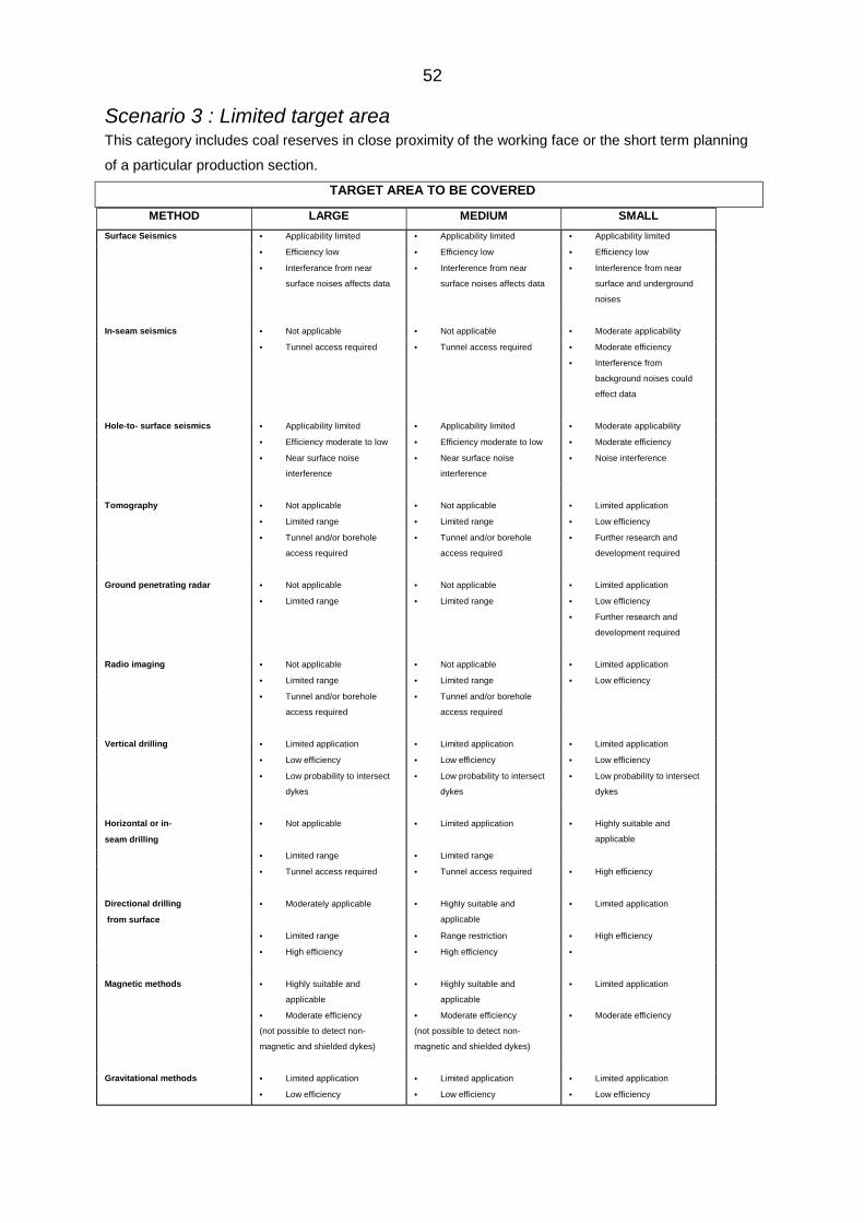
52
Scenario 3 : Limited target areaThis category includes coal reserves in close proximity of the working face or the short term planning
of a particular production section.
TARGET AREA TO BE COVERED
METHOD LARGE MEDIUM SMALL
Surface Seismics • Applicability limited • Applicability limited • Applicability limited
• Efficiency low • Efficiency low • Efficiency low
• Interferance from near
surface noises affects data
• Interference from near
surface noises affects data
• Interference from near
surface and underground
noises
In-seam seismics • Not applicable • Not applicable • Moderate applicability
• Tunnel access required • Tunnel access required • Moderate efficiency
• Interference from
background noises could
effect data
Hole-to- surface seismics • Applicability limited • Applicability limited • Moderate applicability
• Efficiency moderate to low • Efficiency moderate to low • Moderate efficiency
• Near surface noise
interference
• Near surface noise
interference
• Noise interference
Tomography • Not applicable • Not applicable • Limited application
• Limited range • Limited range • Low efficiency
• Tunnel and/or borehole
access required
• Tunnel and/or borehole
access required
• Further research and
development required
Ground penetrating radar • Not applicable • Not applicable • Limited application
• Limited range • Limited range • Low efficiency
• Further research and
development required
Radio imaging • Not applicable • Not applicable • Limited application
• Limited range • Limited range • Low efficiency
• Tunnel and/or borehole
access required
• Tunnel and/or borehole
access required
Vertical drilling • Limited application • Limited application • Limited application
• Low efficiency • Low efficiency • Low efficiency
• Low probability to intersect
dykes
• Low probability to intersect
dykes
• Low probability to intersect
dykes
Horizontal or in-
seam drilling
• Not applicable • Limited application • Highly suitable and
applicable
• Limited range • Limited range
• Tunnel access required • Tunnel access required • High efficiency
Directional drilling
from surface
• Moderately applicable • Highly suitable and
applicable
• Limited application
• Limited range • Range restriction • High efficiency
• High efficiency • High efficiency •
Magnetic methods • Highly suitable and
applicable
• Highly suitable and
applicable
• Limited application
• Moderate efficiency
(not possible to detect non-
magnetic and shielded dykes)
• Moderate efficiency
(not possible to detect non-
magnetic and shielded dykes)
• Moderate efficiency
Gravitational methods • Limited application • Limited application • Limited application
• Low efficiency • Low efficiency • Low efficiency
53
From this table it can therefore be concluded that magnetic methods offer the best
solution to establish the presence of dykes over very large areas. Since its
introduction during the early 1980’s the sophistication of aeromagnetic surveys has
increased significantly and this technique is now routinely used by the South African
coal mining industry. A major limitation of this survey technique is its ability to detect
non-magnetic dykes or dykes shielded by overlying strata with high magnetic
characteristics. Magnetic survey techniques can be used effectively for long term
conceptual planning purposes.
To obtain more accurate information over smaller target areas, directional drilling
techniques offer the best solution. Major progress in the development of this survey
method has been made in South Africa over the last 10 years and it is envisaged
that this system will be more widely used in future.
Despite attempts to develop alternative techniques, in-seam drilling remains the
most reliable and robust method to detect dykes immediately ahead of the mining
face.