executive summary bed - laramie, · pdf fileexecutive summary novel fixed‐bed ... a...
TRANSCRIPT
Executive Summary
Novel Fixed‐Bed Gasifier for Wyoming Coals
Prepared for University of Wyoming
Clean Coal Technologies Research Program Project Code: WY49975EMERY
February 8, 2013
Submitted by:
Emery Energy Company, LLC
159 Pierpont Avenue
Salt Lake City, Utah 84101
Phone: 801‐364‐8283
E‐mail: [email protected]

Table of Contents Abstract ......................................................................................................................................................... 1
Objectives ..................................................................................................................................................... 2
Introduction .................................................................................................................................................. 2
Changes from Original Proposal ............................................................................................................... 3
Results ........................................................................................................................................................... 3
Technical ....................................................................................................................................................... 3
Construction .............................................................................................................................................. 3
Preliminary Design Basis ....................................................................................................................... 3
Design Changes, Fabrication and Installation ....................................................................................... 5
Systems Table ....................................................................................................................................... 8
HazOps and Design Reviews ................................................................................................................. 8
General Project Timeline ...................................................................................................................... 8
Operations ................................................................................................................................................ 9
Parameters of Run ................................................................................................................................ 9
Mass and Energy Summary Tables ..................................................................................................... 10
Block Diagrams .................................................................................................................................... 11
Recommendations/Conclusion ................................................................................................................... 12
Page 1 of 12
Abstract
The Emery Energy Company has novel gasification technology that has the potential to improve
the state of the art technology in fixed bed gasifier configurations. Fixed bed gasification has
traditionally had technical limitations including tar and oil carryover and limited to coarse coal
feeding (i.e. no fines). Emery’s approach aims to maximize the benefits of fixed-bed gasifier
technology while mitigating the technical and economic downsides of such systems. This
approach leverages two well-known and proven processes: updraft fixed-bed gasification &
entrained flow gasification. The potential results will be a new approach to coal gasification
enabling greater feedstock flexibility and low rank coal utilization and effective use of higher
moisture Wyoming coals and capable of operating at altitude with minimal heat and mass
balance penalties.

Page 2 of 12
Objectives
Goal: To demonstrate the Emery Energy Gasification technology on Wyoming Coals at altitude.
Objective 1: Evaluate the overall heat and mass balance to compare relative to existing
processes
Objective 2: Determine the extent of benefit and identify opportune applications
resulting from the syngas outputs and extrapolated economics for larger systems
The methods to be employed included designing, constructing and operating an Emery
FlexFeedTM Gasifier appropriately scaled to test and demonstrate this initial configuration (i.e.
partial embodiment of the full Emery FlexFeedTM technology and integrated performance and
outputs.
Introduction
With Emery Energy’s 2008 Clean Coal Technologies Research Program award we were able to
complete a majority of the construction of the Gasification System. Additionally, Emery Energy
Company has successfully completed additional extended testing of our proprietary FlexFeed™
Gasification system.
Emery’s ability to develop predictability and reliability on the start-up, shut down and steady
state conditions represents a significant milestone of the development and technical performance
of the FlexFeed™ Gasifier technology. This activity has helped reduce the risk of subsequent

Page 3 of 12
and ongoing development activities toward engineering scale up activities and will increase the
appeal of the technology to potential licensees.
Changes from Original Proposal
In December 2010, the Clean Coal Technologies Fund awarded Emery an incremental $285,000
due to an increase in construction costs as well as an increase in labor costs related to
engineering and installation. There were also several project extensions as construction took
longer than anticipated due to weather and some design changes.
Results
Construction was completed in November 2011. Due to limitations when the monies needed to
be spent on the 2009 Clean Coal Technologies Award, Emery switched to the 2009 award before
completing the 2008 award. Emery was unable to complete the full 300 hours of testing under
the 2008 award due to severe weather restrictions. However, a total of 132hours of gasification
were completed and due to changes in our operational methods significant improvements were
made in our ability to run at steady state for longer periods of time which is described in more
detail later in the report.
Technical
Construction
Preliminary Design Basis The initial phase of engineering began in early 2009. Initial ‘entrained flow’ reactor modeling
was performed at at Southern Utah University worked on the E2R reactor modeling. With his

Page 4 of 12
data we were able to determine the size and specific details for the E2R reactor. Although was
sent out for bid, its relative high cost weighed against the benefit to this specific project, we
decided not to go forward with the E2R’s. Below is a chart depicting some of the resulting CFD
modeling.
Entrained Flow Model Development
A Utah-based mechanical engineering firm handled the original engineering and design analysis
on the ash grate including the internal and external bearing, shaft calculations, seals and the
plates. Drawings were generated that were given to fabricator to begin construction. A
separate Utah-based structural engineering firm handled the calculations for the structural piping

Page 5 of 12
and support steel for the gasifier vessel itself. In May 2009, it was decided that a cradle to allow
for removal of the bottom head of the gasifier and also to allow for testing the ash grate prior to
shipping the unit to Laramie. In addition to outsourcing the design engineering, Dr. Richard
Boardman, from Idaho National Lab, also participated in various design review activities prior to
fabrication in May 2009.
Design Changes, Fabrication and Installation After the design basis of the main gasifier reactor was finalized, the balance of the design and
design/build efforts went into sizing the balance of plant major systems. During the design of
major systems, additional weights and stresses were realized and hence some re-engineering was
required to support larger dimension components.
Gasifier Vessel In November 2009, after the gasifier purchase order was issued, it was determine that we needed
to decrease the height of the gasifier. This was to allow for few inches to accommodate the
larger 300 lb pressure flanges (vs. the original design of 150 lb flanges) in order to maintain a
‘code-stamp’ vessel design (at 125 psig), the thicker flanges were required.
The site pad originally specified by the civil contractor that supported the gasifier and flare stack,
didn’t required rebar detailing. It was determined that with the increase in structural support
weight the pad needed additional reinforcement.

Page 6 of 12
Utilizing the gasifier’s bottom head cradle, Emery was able to conduct an ash grate test in Salt
Lake before it was shipped to Laramie in February 2010. Preliminary results validated good
removal rate of the feedstock through the exit, under ambient, non-thermal conditions.
Piping Downstream of the gasifier, the syngas piping was the next major system that would have to be
designed and fabricated to handle the anticipated flows and temperatures of syngas coming from
the gasifier. This effort required multiple iterations by the engineering firm to identify where
and how all the expansion could occur. They recommended that we use three (3) expansion
joints in our piping scheme to deal with the planned expansion and resulting torque. However,
the costs of expansion joints were very expensive, hence we elected to only purchase one
expansion joint and then extend the length of piping (to overcome expansion) in lieu of the other
two expansion joints. This activity then had new impacts on the overall structural steel, which
then, again had to be resized and additional structural members added necessary to accommodate
the new pipe routing.
In January 2010 it was decided that we needed to line the syngas exit pipes with refractory.
This was to accommodate a higher temperature range of the syngas exiting the gasifier.
Steam Boiler In an effort to reduce costs, we purchased a used steam boiler in December 2009. At the time we
didn’t know that we needed to also build an enclosure around the boiler and purchase a furnace
to keep it operational in colder temperatures.

Page 7 of 12
Flare The purchase order for the flare was issued in early October 2009 based on the original design.
In November 2009 it was determined that the flare stack needed to be made taller to improve
destruction efficiency of syngas combustion. This required adjusting stack height, check valves,
pressure gauges and manual ball valves, all required incremental costs
In February 2010 we decided to add a small burner in the flare so that purge gas and ventilation
gases could be fed to it. This required a new manifold, risers, tips and a 150 lb flange connection
to accommodate the 2 new streams.
Feed Pad For feedstock receiving, handling, and overall infrastructure, we had assumed that much more
would be provided by the Western Research Institute. However, the site development ended up
being much more like a ‘greenfield’ development with nothing but land and one natural gas line.
Hence we incurred increases costs (and hence time) to complete feedstock receiving area.
Additionally, since we didn’t have the funds to build solid concrete walls to contain the coal dust
we had to design and concrete block system using old freeway barriers and tarps.
Industrial gases The Oxygen and Nitrogen tanks were much larger than we had originally anticipated. It was
required to pour another concrete pad which had to be large enough to allow for the trucks to
safely fill the tanks. It was also required to place bollards around the tanks for safety reasons, all
per Air Liquide’s requirements

Page 8 of 12
Systems Table
HazOps and Design Reviews There was an initial HazOps/Design Review with WRI conducted in August 2010. Minor design
changes were implemented in response to safety concerns resulting in increasing the number of
thermocouples, additional pressure relief valves and additional carbon monoxide (CO) monitors.
General Project Timeline Gasifier Design Began – May 2009
Construction of Gasifier Began–July 2009
Site Preparation Began – November 2009 (gasifier pad poured)
Systems Design, Fabricated and Installed through WYO I Award
Gasifier Feed Storage
Ash Grate Feed Pad
Plattco's Walls
Nozzles Tarps
Flanges Storm Water Catch Chamber
Piping Industrial gases
Hot Piping Bollards
Cold Piping Design for feed pad
Piping to Industrial Gases Steam Piping OX
Steam Boiler Safety
Boiler LOTO
Enclosure Rattlers
Furnace Confined Space Monitors
Electrical Misc
Junction Boxes Tools
Heaters Solenoids
General Gauges
Nipples
Pipe Fittings

Page 9 of 12
Gasifier Installation – June 2010
Site Construction Completed – November 2011
Operations
Parameters of Run Overall Amount
1 Total coal feed, lbs 30,977 2 Total run time, hrs 131.6 3 Total oxygen, lbs 12,257 4 Total steam feed, lbs 30,834 5 Total syngas produced, scf 5,579,558
Feed stats 1 Feedstock Black Thunder Sub-bituminous coal 2 Maximum feed rate achieved, lbs/h 226 3 Feed size 1/4” to 1” 4 Inert bed material used 3/8” washed crushed gravel 5 Total inert material used, tons ~1.5 6 Density of coal, lbs/ft3 44.8
8 Proximate analysis of feed
26.3 %M, 5.1% Ash, 8972 BTU/lb, 35.4% fixed C, 33.3% v.matter
Gasification stats
1 Average gas composition over the run
8.9% CH4, 20.2% CO, 28.1% CO2, 42.7% H2
2 Average feed rate, lbs/h 226 3 Average steam feed rate, lbs/h 253.5 4 Average oxygen feed rate, scfm 21 (104.7 lbs/h) 5 Average syngas flow rate, scfm 764 6 Average gas heating value, BTU/scf 310.3 (dry basis) 7 Oxygen to coal ratio, lbs/lb 2.16 8 Steam to coal ratio, lbs/lb 1.12 9 Average gasification temperature, F 1387

Page 10 of 12
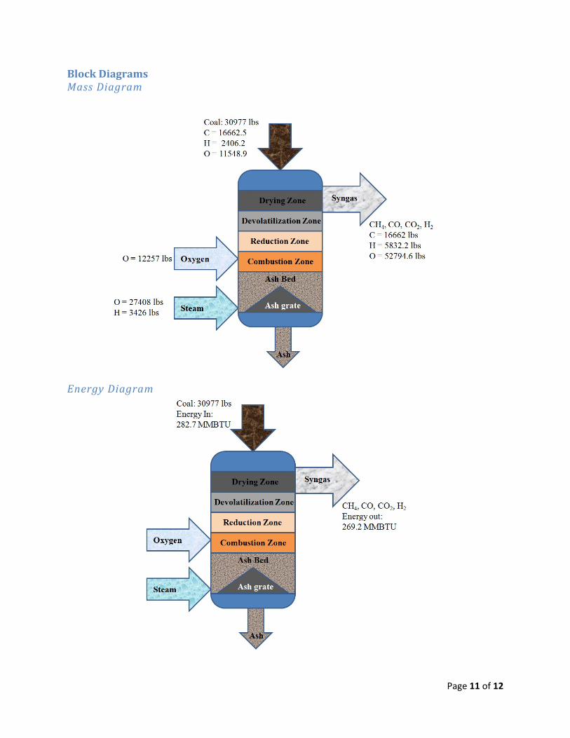
Mass and Energy Summary Tables Mass Balance
Mass In
Coal Wood Steam Oxygen
lbs 30977.0 0.0 30834.0 12257.0
C, lbs 16662.5 0.0 0.0 0.0
H, lbs 2406.2 0.0 3426.0 0.0
O, lbs 11548.9 0.0 27408.0 12257.0
Mass Out
CH4 CO CO2 H2 H2O
lbs 3456.8 13730.1 30013.9 2078.0 26010.6
C total, lbs 16662.5
H total, lbs 5832.2
O total, lbs 52794.6
Energy Balance
Energy in Coal wood out/in
btu 282706083 0
0.9522713
Total Energy out, syngas
btu 269212896.4
Page 11 of 12
Block Diagrams Mass Diagram
Energy Diagram

Page 12 of 12
Recommendations/Conclusion Emery Energy successfully designed, installed and commissioned the FlexFeed Gasifier facility
over the period January 2009 and December 2011. Although various challenges and delays
during design, engineering and construction were encountered, Emery was able to successfully
implement the complete functioning gasifier system. This facility, through the subsequent
contract, was then able to accrue 1500 hours on Wyoming Powder River Basin feedstocks.
During the final operational run at the plant, we achieved a 132 hour continuous run, in which
ash was removed at steady state, which represented a significant achievement over prior runs
during WYO II operational test runs, where ash removal was still be learned.
Based on this experience, our recommendations for improving operational reliability and
maintainability would include the following facility additions:
a. Increase steam capacity to 1500 lbs/hr (vs. the current ~600 lbs/hr) by replacing
the current boiler system, so as to increase capacity of gasifier
b. Add a cyclone for particulate removal immediately downstream from the gasifier
to prevent coal fines from entraining in the syngas exit lines
c. Increase instrumentation to the HMI in the trailer. Approximately 5% - 10% of
the instruments required manual field checking without any feed to the HMI
d. Replace start-up blower (for gasifier burner heat up) with new blower with
additional capacity.