examples manual mill model - mcgill university · 2 example manual surface milling. mill an xy...
TRANSCRIPT

Examples ManualMill model
Ref. 0112 (ing)

INDEX
General examples ........................................................................ 1
Canned cycles ............................................................................13
Multiple machining .....................................................................23
Irregular pockets with islands ..................................................29
Profile editor................................................................................33
User screen customizing programs ........................................41
The cutting speeds and feedrates appearing in this manual are only approximate,they may vary depending on the material of the part and the tools used. Whenmachining one of the parts of these examples, use the speeds recommended bythe tool manufacturer.The tool number will also be different depending on the machine.
========= 0 ========
The information described in this manual may be subject to variations due to technicalmodifications.
FAGOR AUTOMATION, S.Coop. Ltda. reserves the right to modify the contents ofthe manual without prior notice.
WARNING

1
Programming examples:
General examples
8040M8055M
Surface milling. ........................................................................................ 2
Profile definition with tool radius compensation (G40/G41/G42). ................... 3
Arc programming (G02/G03). .................................................................... 4
Tangential entry/exit (G37/G38) and corner rounding (G36). .......................... 5
Mirror image (G10/G11/G12/G13). ............................................................. 6
Pattern rotation (G73). .............................................................................. 7
Pattern rotation (Center of rotation other than part zero). .............................. 8
Selection of the polar origin (G93). ............................................................. 9
Programming in polar coordinates. (I) ....................................................... 10
Programming in polar coordinates. (II) .......................................................11
Programming in polar coordinates. (Archimedes’ Spiral). ........................... 12

2 EXAMPLE MANUAL
Surface milling.
Mill an XY surface down 6mm with a Ø50mm endmill.
Absolute coordinates (G90) Incremental coordinates (G91)
T1 D1 T1 D1 (Tool and tool offset.)
F200 S800 M3 M41 F200 S800 M3 M41 (Cutting conditions.)
G0 G90 X-50 Y0 Z25 G0 G90 X-50 Y0 Z25 (Approach.)
G1 Z6 F200 G1 Z6 F200 (Positioning.)
N10 G1 G90 X-30 Y0 F250 N10 G1 G90 X-30 Y0 F250 (Start milling.)
G91 G1 Z-2 F200 G91 G1 Z-2 F200G90 G1 X230 F250 N20 G1 X260 F250G0 Y40 G0 Y40G1 X-30 N30 G1 X-260G0 Y80 G0 Y40G1 X230 N40 (RPT N20, N30)G0 Y120 (RPT N10, N40) N2
N20 G1 X-30 ;(RPT N10, N20) N2 ;G1 Z20 G1 G90 Z20 (Withdraw the tool.)
G0 X-50 G0 X-50M30 M30 (End of program.)

EXAMPLE MANUAL 3
Profile definition with tool radius compensation (G40/G41/G42).
This example is carried out withclockwise tool radius compensation
(G42).
When starting machining (N10), the tool is placed in front of theprogrammed point and perpendicular to the first path.
When done machining (N150), the tool is placed in front of the programmedpoint and perpendicular to the last path.
N5 T2 D2N10 G0 G90 G42 X0 Y0 Z5 S1000 M3 M41N20 G94 G1 Z-5 F150N30 X10.858 F200 .................................................... Start machining the profile.
N40 G2 X39.142 I14.142 J-5 ................................
N50 G1 X100N60 Y50N70 X90 Y42N80 X80 Y50N90 Y20N100 X55N110 X38.672 Y56.172 ............................................
N120 G3 X10 Y50 I-13.672 J-6.172N130 G1 X10 Y20N140 X0N150 Y0 ...................................................................... Finish machining the profile.
N160 G1 Z5N170 G0 G40 X-30 Y-30 Z20 M30
4 EXAMPLE MANUAL
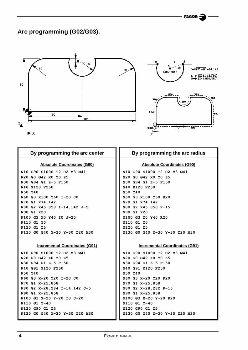
Arc programming (G02/G03).
By programming the arc center
Absolute Coordinates (G90)
N10 G90 S1000 T2 D2 M3 M41N20 G0 G42 X0 Y0 Z5N30 G94 G1 Z-5 F150N40 X120 F250N50 Y40N60 G3 X100 Y60 I-20 J0N70 G1 X74.142N80 G2 X45.858 I-14.142 J-5N90 G1 X20N100 G3 X0 Y40 I0 J-20N110 G1 Y0N120 G1 Z5N130 G0 G40 X-30 Y-30 Z20 M30
Incremental Coordinates (G91)
N10 G90 S1000 T2 D2 M3 M41N20 G0 G42 X0 Y0 Z5N30 G94 G1 Z-5 F150N40 G91 X120 F250N50 Y40N60 G3 X-20 Y20 I-20 J0N70 G1 X-25.858N80 G2 X-28.284 I-14.142 J-5N90 G1 X-25.858N100 G3 X-20 Y-20 I0 J-20N110 G1 Y-40N120 G90 G1 Z5N130 G0 G40 X-30 Y-30 Z20 M30
By programming the arc radius
Absolute Coordinates (G90)
N10 G90 S1000 T2 D2 M3 M41N20 G0 G42 X0 Y0 Z5N30 G94 G1 Z-5 F150N40 X120 F250N50 Y40N60 G3 X100 Y60 R20N70 G1 X74.142N80 G2 X45.858 R-15N90 G1 X20N100 G3 X0 Y40 R20N110 G1 Y0N120 G1 Z5N130 G0 G40 X-30 Y-30 Z20 M30
Incremental Coordinates (G91)
N10 G90 S1000 T2 D2 M3 M41N20 G0 G42 X0 Y0 Z5N30 G94 G1 Z-5 F150N40 G91 X120 F250N50 Y40N60 G3 X-20 Y20 R20N70 G1 X-25.858N80 G2 X-28.282 R-15N90 G1 X-25.858N100 G3 X-20 Y-20 R20N110 G1 Y-40N120 G90 G1 Z5N130 G0 G40 X-30 Y-30 Z20 M30

EXAMPLE MANUAL 5
Tangential entry/exit (G37/G38) and corner rounding (G36).
N10 G0 X15 Y-50 Z5 S1000 T2 D2 M3 M41N20 G1 Z-5 F150N30 G42 G37 R10 Y0 F250N40 G36 R5 X30N50 G36 R12 Y35.01 ................................................
N60 G36 R20 X80 Y0N70 G36 R8 X140N80 G36 R12 X122.68 Y30 ......................................
N90 G36 R20 X65N100 G36 R18 Y68N110 G36 R6 X0N120 G36 R10 Y0N130 G38 R10 X15N140 G40 Y-50N150 G0 X-50 Y-50 Z30 M30
6 EXAMPLE MANUAL
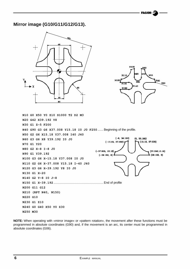
N10 G0 X50 Y0 Z10 S1000 T2 D2 M3N20 G42 X39.192 Y8N30 G1 Z-5 F200N40 G90 G3 G6 X37.008 Y15.18 I0 J0 F250 ...... Beginning of the profile.
N50 G2 G6 X15.18 Y37.008 I40 J40N60 G3 G6 X8 Y39.192 I0 J0N70 G1 Y20N80 G2 X-8 I-8 J0N90 G1 Y39.192N100 G3 G6 X-15.18 Y37.008 I0 J0N110 G2 G6 X-37.008 Y15.18 I-40 J40N120 G3 G6 X-39.192 Y8 I0 J0N130 G1 X-20N140 G2 Y-8 I0 J-8N150 G1 X-39.192 .................................................... End of profile
N200 G11 G12N210 (RPT N40, N150)N220 G10N230 G1 Z10N240 G0 G40 X50 Y0 Z30N250 M30
NOTE: When operating with «mirror image» or «pattern rotation», the movement after these functions must beprogrammed in absolute coordinates (G90) and, if the movement is an arc, its center must be programmed inabsolute coordinates (G06).
Mirror image (G10/G11/G12/G13).

EXAMPLE MANUAL 7
N10 G0 X50 Y0 Z10 S1000 T2 D2 M3N20 G42 X39.192 Y8N30 G1 Z-5 F200N40 G90 G3 G6 X37.008 Y15.18 I0 J0 F250N50 G2 G6 X15.18 Y37.008 I40 J40N60 G3 G6 X8 Y39.192 I0 J0N70 G1 Y20N80 G2 X-8 I-8 J0N90 G1 Y39.192N200 G73 Q90N210 (RPT N40, N200) N3N220 G73N230 G1 Z10N240 G0 G40 X50 Y0 Z30N250 M30
NOTE: When operating with «mirror image» or «pattern rotation», the movement after these functions must beprogrammed in absolute coordinates (G90) and, if the movement is an arc, its center must be programmed inabsolute coordinates (G06).
Pattern rotation (G73).
8 EXAMPLE MANUAL
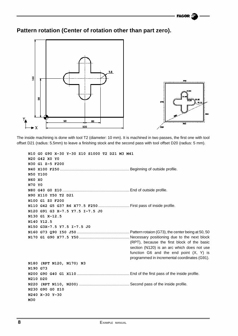
Pattern rotation (Center of rotation other than part zero).
The inside machining is done with tool T2 (diameter: 10 mm). It is machined in two passes, the first one with tooloffset D21 (radius: 5.5mm) to leave a finishing stock and the second pass with tool offset D20 (radius: 5 mm).
N10 G0 G90 X-30 Y-30 Z10 S1000 T2 D21 M3 M41N20 G42 X0 Y0N30 G1 Z-5 F200N40 X100 F250 .......................................................... Beginning of outside profile.N50 Y100N60 X0N70 Y0N80 G40 G0 Z10 ........................................................ End of outside profile.N90 X110 Y50 T2 D21N100 G1 Z0 F200N110 G42 G5 G37 R6 X77.5 F250 .......................... First pass of inside profile.N120 G91 G3 X-7.5 Y7.5 I-7.5 J0N130 G1 X-12.5N140 Y12.5N150 G3X-7.5 Y7.5 I-7.5 J0N160 G73 Q90 I50 J50 ............................................ Pattern rotaion (G73), the center being at 50, 50N170 G1 G90 X77.5 Y50 .......................................... Necessary positioning due to the next block
(RPT), because the first block of the basicsection (N120) is an arc which does not usefunction G6 and the end point (X, Y) isprogrammed in incremental coordinates (G91).
N180 (RPT N120, N170) N3N190 G73N200 G90 G40 G1 X110 ............................................ End of the first pass of the inside profile.N210 D20N220 (RPT N110, N200) .......................................... Second pass of the inside profile.N230 G90 G0 Z10N240 X-30 Y-30M30

EXAMPLE MANUAL 9
Selection of the polar origin (G93).
N10 G0 G90 X100 Y100 Z10 S1000 T2 D2 M3 M41N20 G93 I45 J50 ...................................................... Selection of point A as polar origin.
N30 G42 R30 Q60N40 G1 Z-5 F200N50 G91 Q60 .............................................................. Basic machining (one side)
N60 (RPT N50, N50) N5 .......................................... Machining of the other sides.
N70 G0 G90 G40 Z10N80 X100 Y100N90 M30
To cancel the polar origin, the program may be changed using one of the following options:
First option:
N80 X0 Y0 ......................................Positioning at the point which will be the new polar origin.
N90 G93 ..........................................Presetting the current point as the new polar origin.
N100 X100 Y100N110 M30 ........................................End of program.
Second option:
N80 G93 I0 J0 ..............................Presetting point X0 Y0 as the new polar origin.
N90 X100 Y100N100 M30 ........................................End of program.
10 EXAMPLE MANUAL
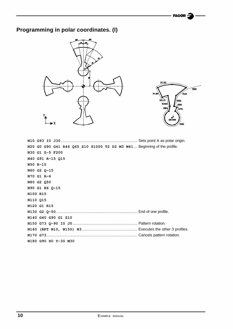
Programming in polar coordinates. (I)
N10 G93 I0 J30 ................................................................. Sets point A as polar origin.
N20 G0 G90 G41 R46 Q65 Z10 S1000 T2 D2 M3 M41 ... Beginning of the profile.
N30 G1 Z-5 F200N40 G91 R-15 Q15N50 R-15N60 G2 Q-15N70 G1 R-6N80 G2 Q50N90 G1 R6 Q-15N100 R15N110 Q15N120 G1 R15N130 G2 Q-50 ..................................................................... End of one profile.
N140 G40 G90 G1 Z10N150 G73 Q-90 I0 J0 ....................................................... Pattern rotation.
N160 (RPT N10, N150) N3 ............................................... Executes the other 3 profiles.
N170 G73 ............................................................................. Cancels pattern rotation.
N180 G90 X0 Y-30 M30

EXAMPLE MANUAL 11
Programming in polar coordinates. (II)
N10 G93 I0 J0 .......................................................... Sets point X0 Y0 as polar origin.
N20 G0 G90 R70 Q45 Z10 S1000 T2 D2 M3 M41N30 G1 Z-5 F200N40 G90 G1 G41 R60 Q45 ........................................ Beginning of profile.
N50 G93 I35.35534 J35.35534N60 G2 G91 Q180N70 G93 I14.14214 J14.14214N80 G3 Q180N90 G93 I21.2132 J-21.2132N100 G2 Q180 ............................................................ End of profile.
N110 G93 I0 J0 ........................................................ Cancels polar origin.
N120 G73 Q-90 .......................................................... Pattern rotation.
N130 (RPT N40, N120) N3 ...................................... Executes the other 3 profiles.
N140 G73 .................................................................... Cancels pattern rotation.
N150 G90 G40 G1 R70N160 G0 Z10N170 R80 Z50 M30

12 EXAMPLE MANUAL
Programming in polar coordinates. (Archimedes’ Spiral).
The espiral increases 10 mm every 360°.
• The first option considers increments of 0.36°, thus, to each angular increment corresponds a radial incrementof 0.01 mm.The number of passes necessary to make the spindle is: 30mm / 0.01mm = 3,000 increments
• The second option considers increments of 0.036°, thus, to each angular increment corresponds a radialincrement of 0.001 mm.The number of passes necessary to make the spindle is: 30mm / 0.001mm = 30,000 incrementsSince the CNC allows repeating a block up to 9999 times, the spiral will have to be made in three blocks.
The basic (first increment)Repeat the first increment 9999 times (total accumulated: 10000)Repeat the previous 2 steps (10,000 times repetion) twice, thus completing the 30000 times.
Fist option:
N10 G0 G90 X0 Y0 Z10 S1000 T5 D5 M3N20 G1 G5 Z-5 F200N30 G91 R0.01 Q-0.36 F100 ....................First incrementN40 (RPT N30, N30) N2999 ......................Rest of incrementsN50 G0 G90 G7 Z10 M30
Second option:
N10 G0 G90 X0 Y0 Z10 S1000 T5 D5 M3N20 G1 G5 Z-5 F200N30 G91 R0.001 Q-0.036 F100 ................First incrementN40 (RPT N30, N30) N9999 ......................Repeats first increment 9999 times (total accumulated: 10000
times)N50 (RPT N30, N40) N2 ............................Repeats previous 2 steps (10,000 times repetion) twice,
thus completing 30,000 times.N60 G0 G90 G7 Z10 M30

13
Programming examples:
Canned cycles
Drilling canned cycle (G81). ............................................................................................ 14
Center punching using the drilling canned cycle with dwell (G82). ..................... 15
Deep hole drilling cycle with constant peck (G83). ................................................. 16
Tapping canned cycle (G84). .......................................................................................... 17
Canned cycles for rectangular pocket (G87) and circular pocket (G88). .......... 18
Modification of the canned cycle parameters (G79). ............................................... 19
Part example 1. .................................................................................................................. 20
Part example 2. .................................................................................................................. 21
8040M8055M

14 EXAMPLE MANUAL
Drilling canned cycle (G81).
T10 D10G0 G90 G43 Z25 S1000 M3 M8 M41
N10 G81 G98 X15 Y15 Z2 I-20 F200N20 X85N30 Y85N40 X15N50 X50 Y75
G93 I50 J50N60 G91 Q-45 N3
G80G0 G90 G44 Z30M30
Definition of the drilling points in: Absolute Cartesian coordinates
Incremental polar coordinates with repetition.
Tool: Ø10mm drill bit.
Cutting conditions:
- S=1000 rpm.- Feedrate: 200 mm/min.
Reference plane
Starting plane

EXAMPLE MANUAL 15
T6 D6G0 G90 G43 Z25 S1800 M3 M8 M41
N10 G82 G99 X-30 Y-50 Z2 I-3 K150 F200N20 G91 X12 Y20 N5N70 G90 G82 G99 X50 Y50 Z-13 I-18 K150N80 G98 Y-50N90 G99 X-50N100 G98 Y50
G80G0 G90 G44 Z30M30
Center punching using the drilling canned cycle with dwell (G82).
Definition of the drilling points in: Absolute Cartesian coordinates
Incremental polar coordinates with repetition.
Tool: 45º center punch.
Cutting conditions:
- S=1800 rpm.- Feedrate: 200 mm/min.
Reference plane
Starting plane

16 EXAMPLE MANUAL
T10 D10G0 G90 G43 Z25 S1000 M3 M41
N10 G83 G99 X-50 Y50 Z2 I-15 J3 F200N20 X50N30 Y - 5 0N40 X - 5 0
G93 I-60 J-60N50 R80 Q30N60 Q70
G80G0 G90 G44 Z30M30
Deep hole drilling cycle with constant peck (G83).
Definition of the drilling points in: Absolute Cartesian coordinates.
Absolute polar coordinates.
Change of polar origin.
Tool: Ø10mm helical drill bit.
Cutting conditions:- S=1000 rpm.
- Feedrate: 200 mm/min.
Reference plane
Starting plane
EXAMPLE MANUAL 17
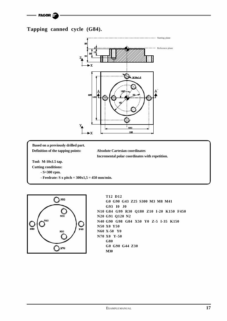
Tapping canned cycle (G84).
T12 D12G0 G90 G43 Z25 S300 M3 M8 M41G93 I0 J0
N10 G84 G99 R30 Q180 Z10 I-20 K150 F450N20 G91 Q120 N2N40 G90 G98 G84 X50 Y0 Z-5 I-35 K150N50 X0 Y50N60 X-50 Y0N70 X0 Y-50
G80G0 G90 G44 Z30M30
Based on a previously drilled part.
Definition of the tapping points: Absolute Cartesian coordinates
Incremental polar coordinates with repetition.
Tool: M-10x1.5 tap.
Cutting conditions:- S=300 rpm.
- Feedrate: S x pitch = 300x1,5 = 450 mm/min.
Reference plane
Starting plane

18 EXAMPLE MANUAL
Definition of the rectangular and circular pocket.
Tool: Ø10mm Endmill
Cutting conditions:
- S=1600 rpm.
- Roughing feedrate: 300mm/min.- Finishing feedrate: 200mm/min.
Canned cycles for rectangular pocket (G87) and circular pocket (G88).
T2 D2G0 G90 G43 Z25 S1600 M3 M42
N10 G88 G99 X30 Y35 Z2 I-10 J-15 B5 C6 D2 H200 L1 F300N20 G98 Y85N30 G87 G98 X90 Y60 Z17 I3 J-20 K40 B4 C6 D2 H200 L1
G80G0 G90 G44 Z30M30
Reference plane
Starting plane

EXAMPLE MANUAL 19
T2 D2G0 G90 G43 Z25 S1600 M3 M42
N10 G87 G99 X40 Y50 Z2 I-10 J20 K40 B4 C6 D2 H200 L1 F300G79 J20 K20
N20 X100 Y100G79 I-18 J40 K20
N30 X140 Y40G80
N70 G0 G90 G44 Z30M30
Modification of the canned cycle parameters (G79).
Definition of the rectangular pocket.Modification of the dimensions and depth of the pockets
Tool: Ø10mm Endmill
Cutting conditions:
- S=1600 rpm.
- Roughing feedrate: 300mm/min.- Finishing feedrate: 200mm/min.
Reference plane
Starting plane
20 EXAMPLE MANUAL
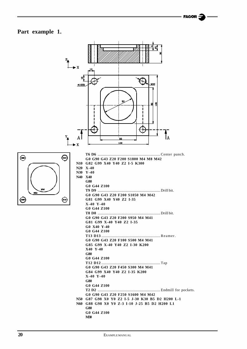
Part example 1.
T6 D6 ................................................................... Center punch.G0 G90 G43 Z20 F200 S1800 M4 M8 M42
N10 G82 G99 X40 Y40 Z2 I-5 K300N20 X-40N30 Y-40N40 X40
G80G0 G44 Z100T9 D9 ................................................................... Drill bit.G0 G90 G43 Z20 F200 S1050 M4 M42G81 G99 X40 Y40 Z2 I-35X-40 Y-40G0 G44 Z100T8 D8 ................................................................... Drill bit.G0 G90 G43 Z20 F200 S950 M4 M41G81 G99 X-40 Y40 Z2 I-35G0 X40 Y-40G0 G44 Z100T13 D13 ............................................................... Reamer .G0 G90 G43 Z20 F100 S500 M4 M41G85 G99 X-40 Y40 Z2 I-30 K200X40 Y-40G80G0 G44 Z100T12 D12 ............................................................... TapG0 G90 G43 Z20 F450 S300 M4 M41G84 G99 X40 Y40 Z2 I-35 K200X-40 Y-40G80G0 G44 Z100T2 D2 ................................................................... Endmill for pockets.G0 G90 G43 Z20 F250 S1600 M4 M42
N50 G87 G98 X0 Y0 Z2 I-5 J-30 K30 B5 D2 H200 L-1N60 G88 G98 X0 Y0 Z-3 I-10 J-25 B5 D2 H200 L1
G80G0 G44 Z100M30

EXAMPLE MANUAL 21
Part example 2.
Initial positioning
G0 G90 G43 X60 Y0 Z5 T2 D2G1 Z0 F250
Outside profile machining
N0 G1 G91 Z-2 F250 S1600 M3 M8N10 G90 G5 G1 G41 G37 R6 X50N20 G2 G6 G36 R15 X39.069 Y-31.203 I0 J0N30 G6 G36 R15 X31.203 Y-39.069 I41.012 J-41.012N40 G6 X0 Y-50 I0 J0N50 G73 Q-90 ................................................. Pattern rotation of -90°.
(RPT N20, N50) N2 ......................... Machines 3rd and 2nd quadrants.(RPT N20, N30)................................. Machines 1st quadrant.G73 .............................................................. Cancels pattern rotation.G6 G38 R6 X50 Y0 I0 J0
N60 G1 G40 G7 X60(RPT N0, N60) N4 ........................... Repeat four times:
"Penetration + Outside milling"F200 S1800 D11 ................................. Offset and finishing conditions(RPT N10, N60)G0 Z10

22 EXAMPLE MANUAL
Slot milling
S1600 T2 D2 M3 M8 M42N100 G0 G90 R38 Q20 Z5 ...................... Approach to point "A"
G1 Z0 F150N102 G91 Z-2N105 G90 G41 G5 R45.5 F250 ........... Section A-BN110 G3 Q70
G93 I12.9967 J35.7083 ........... New polar origin: Point “C”.N120 G91 G3 Q180
G93 I0 J0 ........................................... New polar origin: Point X0 Y0.N130 G2 G90 Q20
G93 I35.7083 J12.9967 ........... New polar origin: Point “A”.N140 G3 G91 Q180
G93 I0 J0 ........................................... New polar origin: Point X0 Y0.N150 G1 G40 G7 G90 R38 Q20 ........... Section B-A
(RPT N102, N150) N4 ................. Repeat 4 times:"Penetration + Milling"
F200 S1800 D21(RPT N105, N150)......................... Finishing pass
N160 G0 G90 Z5G11(RPT N100, N160)......................... Milling the slot of the 4th quadrantG12(RPT N100, N160)......................... Milling the slot of the 3rd quadrantG10 G12(RPT N100, N160)......................... Milling the slot of the 2nd quadrantG10
Center hole milling
S1400 T2 D2 M3 M8 M42G0 G90 X0 Y0 Z5G1 Z0
N200 G1 G91 Z-2 F150N210 G90 G37 R10 G41 G5 X25 F250
G3 G38 R10 X25 Y0 I-25 J0N220 G1 G7 G40 X0
(RPT N200, N220) N4F200 S1600 D21(RPT N210, N220)G0 G90 Z50
Center punching and hole drilling
G99 G81 R58 Q45 Z5 I-5 F200 S1800 T6 D6 M3 M8 M41G0 Q135Q225Q315G99 G81 R58 Q45 Z5 I-20 F200 S900 T14 D14G91 Q90 N3G90 G80 Z100M30
23
Programming examples:
Multiple machining
Multiple machining in a straight line (drilling and tapping). .......................... 24
Multiple machining in a parallelogram pattern (drilling and reaming). ............ 25
Multiple machining in a grid pattern (drilling and reaming). .......................... 26
Bolt-hole pattern machining (drilling). ....................................................... 27
Multiple machining in an arc. ................................................................... 28
8040M8055M

24 EXAMPLE MANUAL
Multiple machining in a straight line (drilling and tapping).Multiple machinings in a straight line may be defined as follows::
Option 1: By defining the length of the path and thenumber of holes.
G0 G43 G90 X0 Y0 Z20 F200 S1500 T7 D7 M3 M41G81 G99 X20 Y10 Z2 I-12 K50G60 A25 X50 K6 P4G80G0 G90 X0 Y0 Z20 F300 S300 T11 D11G84 G98 X20 Y10 Z2 I-12 K10 R0G60 A25 X50 K6 P4G80 G90 X0 Y0M30
Option 2: By defining the length of the path and the stepbetween holes
G0 G43 G90 X0 Y0 Z20 F200 S1500 T7 D7 M3 M41G81 G99 X20 Y10 Z2 I-12 K50
è G60 A25 X50 I10 P4G80G0 G90 X0 Y0 Z20 F300 S300 T11 D11G84 G98 X20 Y10 Z2 I-12 K10 R0
è G60 A25 X50 I10 P4G80 G90 X0 Y0M30
Option 3: By defining the number of holes and the stepbetween them.
G0 G43 G90 X0 Y0 Z20 F200 S1500 T7 D7 M3 M41G81 G99 X20 Y10 Z2 I-12 K50
èè G60 A25 I10 K6 P4G80G0 G90 X0 Y0 Z20 F300 S300 T11 D11G84 G98 X20 Y10 Z2 I-12 K10 R0
è G60 A25 I10 K6 P4G80 G90 X0 Y0M30

EXAMPLE MANUAL 25
Multiple machining in a parallelogram pattern (drilling and reaming).A parallelogram pattern multiple machining may be defined as follows:
Option 1: By defining the length of the path and thenumber of holes.
G0 G90 X0 Y0 Z20 F200 S950 T8 D8 M3 M41G81 G99 X20 Y10 Z2 I-12 K100G61 A15 B75 X90 K4 Y40 D3 P6.007G80G0 G90 X0 Y0 Z20 F100 S500 T13 D13 M3 M41G85 G99 X20 Y10 Z2 I-12 K50G61 A15 B75 X90 K4 Y40 D3 P6.007G80 G90 X0 Y0M30
Option 2: By defining the length of the path and the stepbetween holes.
G0 G90 X0 Y0 Z20 F200 S950 T8 D8 M3 M41G81 G99 X20 Y10 Z2 I-12 K100
è G61 A15 B75 X90 I30 Y40 J20 P6.007G80G0 G90 X0 Y0 Z20 F100 S500 T13 D13 M3 M41G84 G98 X20 Y10 Z2 I-12 K10 R0
è G61 A15 B75 X90 I30 Y40 J20 P6.007G80 G90 X0 Y0M30
Option 3: By defining the number of holes and the stepbetween them.
G0 G90 X0 Y0 Z20 F200 S950 T8 D8 M3 M41G81 G99 X20 Y10 Z2 I-12 K100
è G61 A15 B75 I30 K4 J20 D3 P6.007G80G0 G90 X0 Y0 Z20 F100 S500 T13 D13 M3 M41G84 G98 X20 Y10 Z2 I-12 K10 R0
è G61 A15 B75 I30 K4 J20 D3 P6.007G80 G90 X0 Y0M30

26 EXAMPLE MANUAL
Multiple machining in a grid pattern (drilling and reaming).A grid pattern multiple machining may be defined as follows:
Option 1: By defining the length of the path and thenumber of holes.
G0 G90 X0 Y0 Z20 F200 S950 T8 D8 M3 M41G81 G99 X20 Y10 Z2 I-12 K100G62 A15 B75 X90 K4 Y40 D3G80G0 G90 X0 Y0 Z20 F100 S500 T13 D13 M3 M41G85 G98 X20 Y10 Z2 I-12 K50G62 A15 B75 X90 K4 Y40 D3G80 G90 X0 Y0M30
Option 2: By defining the length of the path and the stepbetween holes.
G0 G90 X0 Y0 Z20 F200 S950 T8 D8 M3 M41G81 G99 X20 Y10 Z2 I-12 K100
è G62 A15 B75 X90 I30 Y40 J20G80G0 G90 X0 Y0 Z20 F100 S500 T13 D13 M3 M41G85 G98 X20 Y10 Z2 I-12 K50
è G62 A15 B75 X90 I30 Y40 J20G80 G90 X0 Y0M30
Option 3: By defining the number of holes and the stepbetween them.
G0 G90 X0 Y0 Z20 F200 S950 T8 D8 M3 M41G81 G99 X20 Y10 Z2 I-12 K100
èè G62 A15 B75 I30 K4 J20 D3G80G0 G90 X0 Y0 Z20 F100 S500 T13 D13 M3 M41G85 G98 X20 Y10 Z2 I-12 K50
èè G62 A15 B75 I30 K4 J20 D3G80 G90 X0 Y0M30

EXAMPLE MANUAL 27
Bolt-hole pattern machining (drilling).A bolt-hole pattern machining may be defined as follows:
Option 1: By defining the number of holes.
G0 G90 X70 Y55 Z20 F200 S1500 T7 D7 M3 M41G81 G99 X110 Y55 Z2 I-12 K50G63 X-40 Y0 K12 C3 F300 P7.011M30
Option 2: By defining the steps between holes.
G0 G90 X70 Y55 Z20 F200 S1500 T7 D7 M3 M41G81 G99 X110 Y55 Z2 I-12 K50
è G63 X-40 Y0 I30 C3 F300 P7.011M30

28 EXAMPLE MANUAL
Multiple machining in an arc.Multiple machining in an arc may be defined as follows:
Option 1: By Defining the number of operations.
G0 G90 X110 Y20 Z20 F100 S1500 T5 D5 M3 M41(MCALL 10)G64 X-40 Y0 B180 K7 C3 F300M30
(SUB 10)G90 G1 Z-10 F100G91 Y-4X8X-8 Y8X-8 Y-8X8Y4G90 Z20
(RET)
Option 2: By defining the step between operations.
G0 G90 X110 Y20 Z20 F100 S1500 T5 D5 M3 M41(MCALL 10)
è G64 X-40 Y0 B180 I30 C3 F300M30
(SUB 10)G90 G1 Z-10 F100G91 Y-4X8X-8 Y8X-8 Y-8X8Y4G90 Z20
(RET)

29
Programming examples:
Irregular pockets with islands
Example 1 of an irregular pocket with islands. .......................................... 30
Example 2 of an irregular pocket with islands. .......................................... 31
8040M8055M

30 EXAMPLE MANUAL
Example 1 of an irregular pocket with islands.
Irregular pocket with islands
T2 D2 ....................................................... Endmill.G0 G90 G43 X0 Y0 Z10 F250 S1600 M3 M42G66 R100 F200 S300 E400G0 G44 X-70 Y0 Z100(GOTO N500) ........................................... Jump to block N500.
N100 G67 A0 B6 C0 I-12 R3 T2 D2 ............. Roughing operation.N200 G68 B0 L-1 T2 D2 ................................. Finishing operation.N300 G1 X-40 Y0 Z0 ....................................... Point "A".
G36 R14 Y-40 ......................................... Section A-B.G36 R14 X40 ........................................... Section B-C.G39 R25 Y40 ........................................... Section C-D.G36 R25 X-40 ......................................... Section D-E.Y0 ............................................................. Section E-A.G0 X12 Y0 ............................................... Point “H”.
N400 G2 G6 I0 J0 ........................................... Circle H-H.
Drilling and Tapping
N500 T9 D9 ....................................................... Ø8.5 mm Drill bitG0 G90 G43 Z100 F200 S1050 M4 M41G83 G98 X0 Y0 Z5 I-12 J3 ................. DrillingTaladrado (P1).G80T7 D7 ....................................................... Broca Ø5 mm.F200 S1500 M4 M42G81 G99 X-24 Y0 Z-10 I-30 K0 ......... Drilling (P2).G63 X24 Y0 I30 C2 F300 ..................... Drilling (P3 to P13).G80G0 Z100T12 D12 ................................................... Tap.G0 G90 G43 Z20 F450 S300 M4 M41G84 G98 X0 Y0 Z5 I-30 ....................... Tapping at point P1.G0 G44 Z50M30

EXAMPLE MANUAL 31
Example 2 of an irregular pocket with islands.
T2 D2M06G0 G90 G43 X0 Y0 Z20 F160 S1600 M3 M42
Irregular pocket with islandsG66 D100 R110 F250 S130 E140G0 G44 Z50(GOTO N300)
N100 G81 Z3 I-15N110 G67 A45 B7.5 C7 I-15 R3 T2 D2 M6N120 G68 B0 L-1 T2 D2 M6N130 G1 X-40 Y0 Z0 ....................................... Point "A".
G36 R25 Y-40 ......................................... Section A-B.G39 R20 X40 ........................................... Section B-C.G36 R25 Y40 ........................................... Section C-D.G39 R20 X-40 ......................................... Section D-E.Y0 ............................................................. Section E-A.G0 X-10.606 Y-10.606 ......................... Point "F".G1 G36 R5 X0 Y-21.213 ....................... Section F-G.G36 R5 X21.213 Y0 ............................... Section G-H.G36 R5 X0 Y21.213 ............................... Section H-I.G36 R5 X-21.213 Y0 ............................. Section I-J.
N140 X-10.606 Y-10.606 ............................... Section J-F.

32 EXAMPLE MANUAL
Arc grooving
N300 T4 D4 ....................................................... Selects the toolM6G19 ........................................................... Selects the YZ plane as
main plane.G15Z ......................................................... Selects the Z axis as vertical
axis.F150 S1200 M3 M42G0 G43 G90 X54.5 Y8.5 Z0G1 X53.5 ................................................. Right groove.
N310 G91 G1 X-1G2 G90 Q180G91 G1 X-1
N320 G3 G90 Q0(RPT N310, N320) N6G0 G90 Z10X-36.5 ..................................................... Left groove.Z0(RPT N310, N320) N7G0 G90 G17 G44 Z50
Drilling
T9 D9 ....................................................... Selects the toolM6F200 S1050 M4 M41G0 G43 G90 X40 Y40 Z20G83 G99 Z3 I-13 J3 ............................. Drilling at point "A".
N400 X-40 ......................................................... Drilling at point "B".Y-40 ......................................................... Drilling at point "C".X40 ........................................................... Drilling at point "D".
N410 G80G0 G44 Z60
TappingT12 D12 ................................................... Selects the toolM6F450 S300 M4 M41G0 G43 G90 X40 Y40 Z20G84 G99 Z5 I-30 ................................... Tapping of hole "A"(RPT N400, N410) ................................. Tapping of holes "B", "C"
and "D".G0 G44 Z60M30

33
Programming examples:
Profile editor
Profile editor. Example 1. ........................................................................ 34
Profile editor. Example 2. ........................................................................ 35
Profile editor. Example 3. ........................................................................ 36
Profile editor. Example 4. ........................................................................ 37
Profile editor. Example 5. ........................................................................ 38
Profile editor. Example 6. ........................................................................ 39
Profile editor. Example 7. ........................................................................ 40
8040M8055M

34 EXAMPLE MANUAL
Profile editor. Example 1.
PROFILE DEFINITION WITHOUT ROUNDINGS, CHAMFERS, TANGENTIAL ENTRY AND EXIT
• STARTING POINT : X = 80 Y =-20
• STRAIGHT LINE : X = 80 Y = 20• STRAIGHT LINE : X = 20 Y = 20• STRAIGHT LINE : X = 20 Y = 80
• STRAIGHT LINE : X = 60 Y = 80• CCW ARC : X = 100 Y = 80 Xcenter = 80 Ycenter = 80 Radius = 20• STRAIGHT LINE : X = 140 Y = 80
• STRAIGHT LINE : X = 140 Y = 20• STRAIGHT LINE : X = 80 Y = 20• STRAIGHT LINE : X = 80 Y =-20
DEFINITION OF ROUNDINGS, CHAMFERS, TANGENTIAL ENTRY AND EXIT
Select the CORNERS option and define:TANGENTIAL ENTRY ......... Select point "1" .............. Press ENTER ...... Set radius = 5CHAMFER......................... Select point "2" .............. Press ENTER ...... Set size = 10ROUNDING........................ Select point "3" .............. Press ENTER ...... Set radius = 10ROUNDING........................ Select point "4" .............. Press ENTER ...... Set radius = 5ROUNDING........................ Select point "5" .............. Press ENTER ...... Set radius = 5ROUNDING........................ Select point "6" .............. Press ENTER ...... Set radius = 10CHAMFER......................... Select point "7" .............. Press ENTER ...... Set size = 10TANGENTIAL EXIT.............. Select point "1" .............. Press ENTER ...... Set radius = 5
Press ESC to quit the Corners option .
END OF EDITING
Select the softkeys END+SAVE PROFILE. The CNC quits the profile editing mode and displays, in ISO code,the program that has been generated.

EXAMPLE MANUAL 35
Profile editor. Example 2.
PROFILE DEFINITION
• STARTING POINT : X= 0 Y= -70• CW ARC (1) : Xcenter= 0 Ycenter= 0 Radius= 70• CW ARC (2) : Radius= 350 Tangent= Yes• CW ARC (3) : Xcenter= 0 Ycenter= 120 Radius= 30 Tangent= Yes
The CNC shows all the possible options for section 2. Select the right one
• CW ARC (4) : Radius= 350 Tangent= Yes• CW ARC (5) : X= 0 Y= -70 Xcenter= 0 Ycenter= 0 Radius= 70 Tangent= Yes
The CNC shows all the possible options for section 4. Select the right one
END OF EDITING
Select the softkeys END+SAVE PROFILE. The CNC quits the profile editing mode and displays, in ISO code,the program that has been generated.

36 EXAMPLE MANUAL
Profile editor. Example 3.
PROFILE DEFINITION
• STARTING POINT : X = 40 Y = 120• CW ARC : Xcenter = 60 Ycenter = 120 Radius = 20• CCW ARC (1) : Radius = 150 Tangent = Yes• CW ARC : Xcenter = 200 Ycenter = 150 Radius = 30 Tangent = Yes
The CNC shows all the possible options for section 1. Select the right one.
• CCW ARC (2) : Radius = 180 Tangent = Yes• CW ARC : Xcenter = 160 Ycenter = 50 Radius = 20 Tangent = Yes
The CNC shows all the possible options for section 2. Select the right one.
• CCW ARC (3) : Radius = 100 Tangent = Yes• CW ARC : X= 40 Y= 120 Xcenter= 60 Ycenter= 120 Tangent= Yes
The CNC shows all the possible options for section 3. Select the right one.
END OF EDITING
Select the softkeys END+SAVE PROFILE. The CNC quits the profile editing mode and displays, in ISO code,the program that has been generated.
EXAMPLE MANUAL 37
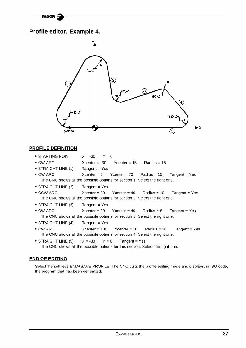
Profile editor. Example 4.
PROFILE DEFINITION
• STARTING POINT : X = -30 Y = 0
• CW ARC : Xcenter = -30 Ycenter = 15 Radius = 15• STRAIGHT LINE (1) : Tangent = Yes• CW ARC : Xcenter = 0 Ycenter = 70 Radius = 15 Tangent = Yes
The CNC shows all the possible options for section 1. Select the right one.
• STRAIGHT LINE (2) : Tangent = Yes• CCW ARC : Xcenter = 30 Ycenter = 40 Radius = 10 Tangent = Yes
The CNC shows all the possible options for section 2. Select the right one.
• STRAIGHT LINE (3) : Tangent = Yes• CW ARC : Xcenter = 80 Ycenter = 40 Radius = 8 Tangent = Yes
The CNC shows all the possible options for section 3. Select the right one.
• STRAIGHT LINE (4) : Tangent = Yes
• CW ARC : Xcenter = 100 Ycenter = 10 Radius = 10 Tangent = YesThe CNC shows all the possible options for section 4. Select the right one.
• STRAIGHT LINE (5) : X = -30 Y = 0 Tangent = YesThe CNC shows all the possible options for this section. Select the right one.
END OF EDITING
Select the softkeys END+SAVE PROFILE. The CNC quits the profile editing mode and displays, in ISO code,the program that has been generated.
38 EXAMPLE MANUAL
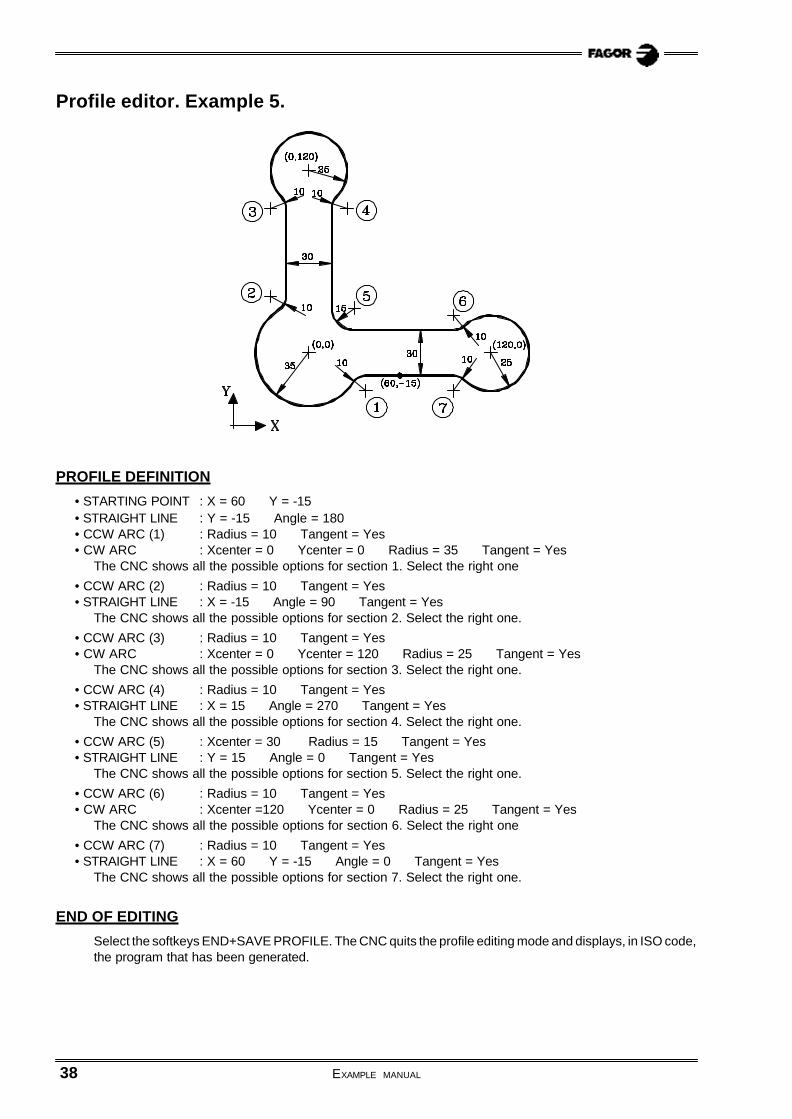
Profile editor. Example 5.
PROFILE DEFINITION
• STARTING POINT : X = 60 Y = -15• STRAIGHT LINE : Y = -15 Angle = 180• CCW ARC (1) : Radius = 10 Tangent = Yes• CW ARC : Xcenter = 0 Ycenter = 0 Radius = 35 Tangent = Yes
The CNC shows all the possible options for section 1. Select the right one
• CCW ARC (2) : Radius = 10 Tangent = Yes• STRAIGHT LINE : X = -15 Angle = 90 Tangent = Yes
The CNC shows all the possible options for section 2. Select the right one.
• CCW ARC (3) : Radius = 10 Tangent = Yes• CW ARC : Xcenter = 0 Ycenter = 120 Radius = 25 Tangent = Yes
The CNC shows all the possible options for section 3. Select the right one.
• CCW ARC (4) : Radius = 10 Tangent = Yes• STRAIGHT LINE : X = 15 Angle = 270 Tangent = Yes
The CNC shows all the possible options for section 4. Select the right one.
• CCW ARC (5) : Xcenter = 30 Radius = 15 Tangent = Yes• STRAIGHT LINE : Y = 15 Angle = 0 Tangent = Yes
The CNC shows all the possible options for section 5. Select the right one.
• CCW ARC (6) : Radius = 10 Tangent = Yes• CW ARC : Xcenter =120 Ycenter = 0 Radius = 25 Tangent = Yes
The CNC shows all the possible options for section 6. Select the right one
• CCW ARC (7) : Radius = 10 Tangent = Yes• STRAIGHT LINE : X = 60 Y = -15 Angle = 0 Tangent = Yes
The CNC shows all the possible options for section 7. Select the right one.
END OF EDITING
Select the softkeys END+SAVE PROFILE. The CNC quits the profile editing mode and displays, in ISO code,the program that has been generated.

EXAMPLE MANUAL 39
Profile editor. Example 6.
PROFILE DEFINITION
• STARTING POINT : X = 100 Y = 20• STRAIGHT LINE : X = 80 Y = 20• STRAIGHT LINE : X = 80 Angle = 90• CCW ARC (1) : Xcenter = 75 Radius = 5 Tangent = Yes• CCW ARC (2) : Xcenter = 100 Radius = 150 Tangent = Yes• CW ARC : Xcenter = 40 Ycenter = 80 Radius = 20 Tangent = Yes
The CNC shows all the possible options for section 2. Select the right one.
The CNC shows all the possible options for section 1. Select the right one.
• CW ARC (3) : Radius = 200 Tangent = Yes• CW ARC : Xcenter = 80 Ycenter = 160 Radius = 10 Tangent = Yes
The CNC shows all the possible options for section 3. Select the right one
• CCW ARC (4) : Radius = 40 Tangent = Yes• CW ARC : Xcenter = 120 Ycenter = 160 Radius = 10 Tangent = Yes
The CNC shows all the possible options for section 4. Select the right one.
• CW ARC (5) : Radius = 200 Tangent = Yes• CW ARC : Xcenter = 160 Ycenter = 80 Radius = 20 Tangent = Yes
The CNC shows all the possible options for section 5. Select the right one
• CCW ARC (6) : Xcenter = 100 Radius = 150 Tangent = YesThe CNC shows all the possible options for section 6. Select the right one.
• CCW ARC (7) : Xcenter = 125 Radius = 5 Tangent = YesThe CNC shows all the possible options for section 7. Select the right one.
• STRAIGHT LINE (8) : X = 120 Y = 20 Tangent = YesThe CNC shows all the possible options for section 8. Select the right one.
• STRAIGHT LINE : X = 100 Y = 20
DEFINITION OF ROUNDINGS "A" and "B"
Select the CORNERS option and define:
ROUNDING........................ Select point "A" ............. Press ENTER .......Set radius = 5ROUNDING........................ Select point "B" ............. Press ENTER .......Set radius = 5
Press [ESC] to quit the Corners option.
END OF EDITING
Select the softkeys END+SAVE PROFILE. The CNC quits the profile editing mode and displays, in ISO code,the program that has been generated.

40 EXAMPLE MANUAL
Profile editor. Example 7.
PROFILE DEFINITION
• STARTING POINT : X = -60 Y = 0• CW ARC : Xcenter = -60 Ycenter = 20 Radius = 20• STRAIGHT LINE (1) : Angle = 60 Tangent = Yes
The CNC shows all the possible options for section 1. Select the right one
• CCW ARC (2) : Radius = 15 Tangent = Yes• STRAIGHT LINE (3) : Angle = -70 Tangent = Yes• CW ARC : Xcenter = -40 Ycenter = 110 Radius = 25 Tangent = Yes
The CNC shows all the possible options for section 3. Select the right one
The CNC shows all the possible options for section 2. Select the right one
• CCW ARC (4) : Radius = 15 Tangent = Yes• STRAIGHT LINE : Y = 130 Angle = 0 Tangent = Yes
The CNC shows all the possible options for section 4. Select the right one
• CW ARC (5) : Xcenter = 50 Radius = 15 Tangent = YesThe CNC shows all the possible options for section 5. Select the right one
• CCW ARC (6) : Radius = 40 Tangent = Yes• STRAIGHT LINE : X = 50 Angle = 270 Tangent = Yes
The CNC shows all the possible options for section 6. Select the right one
• CCW ARC (7) : Radius = 10 Tangent = Yes• CW ARC : Xcenter = 40 Ycenter = 30 Radius = 30 Tangent = Yes
The CNC shows all the possible options for section 7. Select the right one
• STRAIGHT LINE (8) : X = -60 Y = 0 Tangent = YesThe CNC shows all the possible options for section 8. Select the right one
END OF EDITING
Select the softkeys END+SAVE PROFILE. The CNC quits the profile editing mode and displays, in ISO code,the program that has been generated.

8040M8055M
41
Programming examples:
User screen customizing programs
Machine diagnosis. ................................................................................ 42
Slot milling. ........................................................................................... 50

42 EXAMPLE MANUAL
Machine diagnosis.
This example shows:
a.- How to write a user screen customizing program.
In order to be able to execute this program in the user channel of the MANUAL mode, generalmachine parameter «USERMAN» must be set with the program number.
For better understanding, the explanation is divided into parts indicating the section of the program andthe creation of the corresponding screens (pages) and symbols. The different parts are:
- Part 1 : It requests the access code (password).- Part 2 : It shows the status of inputs I1 to I40.
(it uses user page 2 and the symbols 21 and 22)- Part 3 : It shows the status of outputs O1 to O18.
(It uses user page 3 and the symbols 21 and 22)- Part 4 : It shows the consumption of the motors.
(It uses user page 4 and the symbols 0 to 20)To go to the previous or next page, use the «previous page» and «next page» keys.
b.- How to create a user screen (page).
c.- How to create a user symbol.
Part 1: "Request password"N100 (IB1= INPUT “PASSWORD = ”, 6) ..................... Requests the password
(IF IB1 NE (123456) GOTO N100) ................... If the password is not correct (123456), it requestsit again.
;N200 ............................................................................... If it is correct, the program continues on line
N200 (part 2)
EXAMPLE MANUAL 43
Part 2: "Shows the status of inputs I1 through I40"
Program lines (main program).
N200 (PAGE2) ........................................... Shows page 2(KEY=0) ........................................... Clears the memory of the last key pressed.
N210 (P100=PLCI1) ................................. Assigns to parameter P100, the value of inputs I1 to I32(P199=85) ....................................... Row where to insert the symbol(CALL 2) ......................................... Call to subroutine (it inserts symbols)(P100=PLCI11) ............................... Assigns to parameter P100 the value of inputs I11 to I42(P199=155) ..................................... Row where to insert the symbol(CALL 2) ......................................... Call to subroutine (it inserts symbols)(P100=PLCI21) ............................... Assigns to parameter P100 the value of inputs I21 to I52(P199=225) ..................................... Row where to insert the symbol(CALL 2) ......................................... Row where to insert the symbol(P100=PLCI31) ............................... Asigna al parámetro P100 el valor de las entradas I31 a I62(P199=295) ..................................... Row where to insert the symbol(CALL 2) ......................................... Row where to insert the symbol(IF KEY EQ $FFAF GOTO N300) ... If “next page” has been pressed, it goes on to line N300 (part 3)(GOTO N210) ................................... If not, refresh the status of the inputs.
Program lines (subroutine that indicates the status of a row of inputs).
This subroutine analyzes the 10 least significant bits of parameter P100. If the bit is set to «1», it insertssymbol 21 (lamp lit, red color) and if it is set to «0», it inserts symbol 22 (lamp off, background color).
Call parameters:- P100 = Value of the inputs to be displayed.- P199 = Row where the symbols are to be inserted.
(SUB 2)(IF (P100 AND 1) EQ 0 SYMBOL 22,80,P199 ELSE SYMBOL 21,80,P199)(IF (P100 AND 2) EQ 0 SYMBOL 22,130,P199 ELSE SYMBOL 21,130,P199)(IF (P100 AND 4) EQ 0 SYMBOL 22,180,P199 ELSE SYMBOL 21,180,P199)(IF (P100 AND 8) EQ 0 SYMBOL 22,230,P199 ELSE SYMBOL 21,230,P199)(IF (P100 AND $10) EQ 0 SYMBOL 22,280,P199 ELSE SYMBOL 21,280,P199)(IF (P100 AND $20) EQ 0 SYMBOL 22,330,P199 ELSE SYMBOL 21,330,P199)(IF (P100 AND $40) EQ 0 SYMBOL 22,380,P199 ELSE SYMBOL 21,380,P199)(IF (P100 AND $80) EQ 0 SYMBOL 22,430,P199 ELSE SYMBOL 21,430,P199)(IF (P100 AND $100) EQ 0 SYMBOL 22,480,P199 ELSE SYMBOL 21,480,P199)(IF (P100 AND $200) EQ 0 SYMBOL 22,530,P199 ELSE SYMBOL 21,530,P199)
(RET)
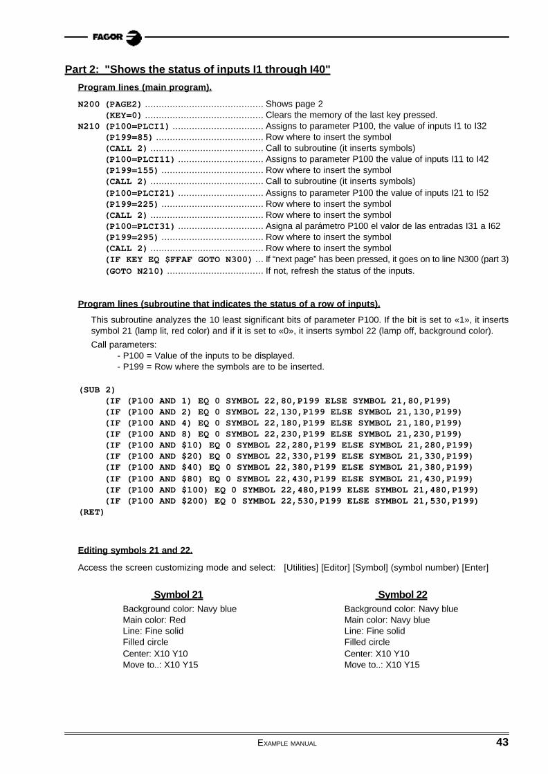
Editing symbols 21 and 22.
Access the screen customizing mode and select: [Utilities] [Editor] [Symbol] (symbol number) [Enter]
Symbol 21 Symbol 22Background color: Navy blue Background color: Navy blueMain color: Red Main color: Navy blueLine: Fine solid Line: Fine solidFilled circle Filled circleCenter: X10 Y10 Center: X10 Y10Move to..: X10 Y15 Move to..: X10 Y15

44 EXAMPLE MANUAL
Editing page 2
Access the screen customizing mode and select: [Utilities] [Edit] [Page] 2 [Enter]
Select background color: Navy blue
Edit the following texts:
Edit the following circles (unfilled) with white main color and line type: Fine solid.
Main color Size Text Position Main color Size Text Position Main color Size Text Position
White Large INPUTS X226 Y10 White Small I13 X180 Y140 White Small I27 X380 Y210
Red Large INPUTS X224 Y8 White Small I14 X230 Y140 White Small I28 X430 Y210
White Small I1 X80 Y70 White Small I15 X280 Y140 White Small I29 X480 Y210
White Small I2 X130 Y70 White Small I16 X330 Y140 White Small I30 X530 Y210
White Small I3 X180 Y70 White Small I17 X380 Y140 White Small I31 X80 Y280
White Small I4 X230 Y70 White Small I18 X430 Y140 White Small I32 X130 Y280
White Small I5 X280 Y70 White Small I19 X480 Y140 White Small I33 X180 Y280
White Small I6 X330 Y70 White Small I20 X530 Y140 White Small I34 X230 Y280
White Small I7 X380 Y70 White Small I21 X80 Y210 White Small I35 X280 Y280
White Small I8 X430 Y70 White Small I22 X130 Y210 White Small I36 X330 Y280
White Small I9 X480 Y70 White Small I23 X180 Y210 White Small I37 X380 Y280
White Small I10 X530 Y70 White Small I24 X230 Y210 White Small I38 X430 Y280
White Small I11 X80 Y140 White Small I25 X280 Y210 White Small I39 X480 Y280
White Small I12 X130 Y140 White Small I26 X330 Y210 White Small I40 X530 Y280
Main color Center Move to... Main color Center Move to... Main color Center Move to...
White X90 Y95 X90 Y102 White X290 Y165 X290 Y172 White X490 Y235 X490 Y242
White X140 Y95 X140 Y102 White X340 Y165 X340 Y172 White X540 Y235 X540 Y242
White X190 Y95 X190 Y102 White X390 Y165 X390 Y172 White X90 Y305 X90 Y312
White X240 Y95 X240 Y102 White X440 Y165 X440 Y172 White X140 Y305 X140 Y312
White X290 Y95 X290 Y102 White X490 Y165 X490 Y172 White X190 Y305 X190 Y312
White X340 Y95 X340 Y102 White X540 Y165 X540 Y172 White X240 Y305 X240 Y312
White X390 Y95 X390 Y102 White X90 Y235 X90 Y242 White X290 Y305 X290 Y312
White X440 Y95 X440 Y102 White X140 Y235 X140 Y242 White X340 Y305 X340 Y312
White X490 Y95 X490 Y102 White X190 Y235 X190 Y242 White X390 Y305 X390 Y312
White X540 Y95 X540 Y102 White X240 Y235 X240 Y242 White X440 Y305 X440 Y312
White X90 Y165 X90 Y172 White X290 Y235 X290 Y242 White X490 Y305 X490 Y312
White X140 Y165 X140 Y172 White X340 Y235 X340 Y242 White X540 Y305 X540 Y312
White X190 Y165 X190 Y172 White X390 Y235 X390 Y242
White X240 Y165 X240 Y172 White X440 Y235 X440 Y242

EXAMPLE MANUAL 45
Part 3: "Shows the status of outputs O1 to O18"
Program lines (main program).
N300 (PAGE3) ........................................... Shows page 3(KEY = 0 ) ..................................... Clears memory of last key pressed
N310 (P100=PLCO1) ................................. Assigns to parameter P100 the value of the outputs O1 to O32(P199=85) ....................................... Row where to insert the symbol(CALL 3) ......................................... Call to subroutine (it inserts symbols)(P100=PLCO10) ............................... Assigns to parameter P100 the value of the outputs O10 to O41(P199=155) ..................................... Row where to insert the symbol(CALL 3) ......................................... Call to subroutine (it inserts symbols)(IF KEY EQ $FFA5 GOTO N200) ... If "previous page" has been pressed, it goes on to line N200 (part
2)(IF KEY EQ $FFAF GOTO N400) ... If "next page" has been pressed, it goes on to line N400 (part
4)(GOTO N310) ................................... If not, it refreshes the status of the outputs
Program lines (subroutine that indicates the status of a row of outputs).
This subroutine analyzes the 10 least significant bits of parameter P100. If the bit is set to «1», it insertssymbol 21 (lamp on, red color), if it is set to «0», it inserts symbol 22 (lamp off. background color).
Call parameters:- P100 = Value of the outputs to be displayed.- P199 = Row where to insert the symbols.
(SUB 3)(IF (P100 AND 1) EQ 0 SYMBOL 22,105,P199 ELSE SYMBOL 21,105,P199)(IF (P100 AND 2) EQ 0 SYMBOL 22,155,P199 ELSE SYMBOL 21,155,P199)(IF (P100 AND 4) EQ 0 SYMBOL 22,205,P199 ELSE SYMBOL 21,205,P199)(IF (P100 AND 8) EQ 0 SYMBOL 22,255,P199 ELSE SYMBOL 21,255,P199)(IF (P100 AND $10) EQ 0 SYMBOL 22,305,P199 ELSE SYMBOL 21,305,P199)(IF (P100 AND $20) EQ 0 SYMBOL 22,355,P199 ELSE SYMBOL 21,355,P199)(IF (P100 AND $40) EQ 0 SYMBOL 22,405,P199 ELSE SYMBOL 21,405,P199)(IF (P100 AND $80) EQ 0 SYMBOL 22,455,P199 ELSE SYMBOL 21,455,P199)(IF (P100 AND $100) EQ 0 SYMBOL 22,505,P199 ELSE SYMBOL 21,505,P199)
(RET)

46 EXAMPLE MANUAL
Editing page 3
Access the screen customizing mode and select: [Utilities] [Editor] [Page] 3 [Enter]
Select background color: Navy blue
Edit the following texts:
Edit the following circles (unfilled) with white main color and line type: Fine solid
Main color Size Text Position Main color Size Text Position Main color Size Text Position
White Large OUTPUTS X235 Y10 White Small O6 X355 Y70 White Small O13 X255 Y140
Red Large OUTPUTS X233 Y8 White Small O7 X405 Y70 White Small O14 X305 Y140
White Small O1 X105 Y70 White Small O8 X455 Y70 White Small O15 X355 Y140
White Small O2 X155 Y70 White Small O9 X505 Y70 White Small O16 X405 Y140
White Small O3 X205 Y70 White Small O10 X105 Y140 White Small O17 X455 Y140
White Small O4 X255 Y70 White Small O11 X155 Y140 White Small O18 X505 Y140
White Small O5 X305 Y70 White Small O12 X205 Y140
Main color Center Move to... Main color Center Move to... Main color Center Move to...
White X115 Y95 X115 Y102 White X415 Y95 X415 Y102 White X265 Y165 X265 Y172
White X165 Y95 X165 Y102 White X465 Y95 X465 Y102 White X315 Y165 X315 Y172
White X215 Y95 X215 Y102 White X515 Y95 X515 Y102 White X365 Y165 X365 Y172
White X265 Y95 X265 Y102 White X115 Y165 X115 Y172 White X415 Y165 X415 Y172
White X315 Y95 X315 Y102 White X165 Y165 X165 Y172 White X465 Y165 X465 Y172
White X365 Y95 X365 Y102 White X215 Y165 X215 Y172 White X515 Y165 X515 Y172

EXAMPLE MANUAL 47
Part 4: "Shows the consumption of motors"
The speed drives have an analog output (0 to 10V) proportional to the current consumed by the motor.
In this example, the following connections have been made:- The X axis drive’s current output is connected to the analog input 1 of the CNC.- The Y axis drive’s current output is connected to the analog input 2 of the CNC.- The Z axis drive’s current output is connected to the analog input 3 of the CNC.- The spindle (S) drive’s current output is connected to the analog input 4 of the CNC.
Therefore, variables "ANAI1”, “ANAI2”, “ANAI3” and “ANAI4” show the analog voltage corresponding to thecurrents of the X, Y and Z axes and of the spindle S.21 symbols (0-20) are used to display the value of the current, in increments corresponding to 0.5V.To select the right symbol each time, the formula: "ABS ROUND (ANAI1/0.5)" is applied. In other words, therounded-up absolute value of the result of the operation "ANAI1/0.5".
Program lines.
N400 (PAGE 4) .......................................................... Shows page 4.(KEY = 0) ........................................................ Clears memory of last key pressed.
N410 (SYMBOL ABS ROUND (ANAI1/0.5), 130, 120)(SYMBOL ABS ROUND (ANAI2/0.5), 130, 170)(SYMBOL ABS ROUND (ANAI3/0.5), 130, 220)(SYMBOL ABS ROUND (ANAI4/0.5), 130, 270)(IF KEY EQ $FFA5 GOTO N300) .................... If "previous page" has been pressed, it goes on to
line N300 (part 3)(GOTO N410) .................................................... If not, it refreshes the motor consumption.
Editing symbols 0-20
Access the screen customizing mode and select: [Utilities] [Editor] [Symbol] (symbol number) [Enter]
FILLED RECTANGLE FINE SOLID LINE
Green Yellow Red Gray Green Yellow Red
From to From to From to From to From to From to From to
SYMBOL 0 --- --- --- --- --- --- X0 Y0 X400 Y30 X100 Y0 X100 Y30 X200 Y0 X200 Y30 X300 Y0 X300 Y30
SYMBOL 1 X0 Y0 X20 Y30 --- --- --- --- X20 Y0 X400 Y30 X100 Y0 X100 Y30 X200 Y0 X200 Y30 X300 Y0 X300 Y30
SYMBOL 2 X0 Y0 X40 Y30 --- --- --- --- X40 Y0 X400 Y30 X100 Y0 X100 Y30 X200 Y0 X200 Y30 X300 Y0 X300 Y30
SYMBOL 3 X0 Y0 X60 Y30 --- --- --- --- X60 Y0 X400 Y30 X100 Y0 X100 Y30 X200 Y0 X200 Y30 X300 Y0 X300 Y30
SYMBOL 4 X0 Y0 X80 Y30 --- --- --- --- X80 Y0 X400 Y30 X100 Y0 X100 Y30 X200 Y0 X200 Y30 X300 Y0 X300 Y30
SYMBOL 5 X0 Y0 X100 Y30 --- --- --- --- X100 Y0 X400 Y30 --- --- X200 Y0 X200 Y30 X300 Y0 X300 Y30
SYMBOL 6 X0 Y0 X120 Y30 --- --- --- --- X120 Y0 X400 Y30 --- --- X200 Y0 X200 Y30 X300 Y0 X300 Y30
SYMBOL 7 X0 Y0 X140 Y30 --- --- --- --- X140 Y0 X400 Y30 --- --- X200 Y0 X200 Y30 X300 Y0 X300 Y30
SYMBOL 8 X0 Y0 X160 Y30 --- --- --- --- X160 Y0 X400 Y30 --- --- X200 Y0 X200 Y30 X300 Y0 X300 Y30
SYMBOL 9 X0 Y0 X180 Y30 --- --- --- --- X180 Y0 X400 Y30 --- --- X200 Y0 X200 Y30 X300 Y0 X300 Y30
SYMBOL 10 X0 Y0 X200 Y30 --- --- --- --- X200 Y0 X400 Y30 --- --- --- --- X300 Y0 X300 Y30
SYMBOL 11 X0 Y0 X200 Y30 X200 Y0 X220 Y30 --- --- X220 Y0 X400 Y30 --- --- --- --- X300 Y0 X300 Y30
SYMBOL 12 X0 Y0 X200 Y30 X200 Y0 X240 Y30 --- --- X240 Y0 X400 Y30 --- --- --- --- X300 Y0 X300 Y30
SYMBOL 13 X0 Y0 X200 Y30 X200 Y0 X260 Y30 --- --- X260 Y0 X400 Y30 --- --- --- --- X300 Y0 X300 Y30
SYMBOL 14 X0 Y0 X200 Y30 X200 Y0 X280 Y30 --- --- X280 Y0 X400 Y30 --- --- --- --- X300 Y0 X300 Y30
SYMBOL 15 X0 Y0 X200 Y30 X200 Y0 X300 Y30 --- --- X300 Y0 X400 Y30 --- --- --- --- --- ---
SYMBOL 16 X0 Y0 X200 Y30 X200 Y0 X300 Y30 X300 Y0 X320 Y30 X320 Y0 X400 Y30 --- --- --- --- --- ---
SYMBOL 17 X0 Y0 X200 Y30 X200 Y0 X300 Y30 X300 Y0 X340 Y30 X340 Y0 X400 Y30 --- --- --- --- --- ---
SYMBOL 18 X0 Y0 X200 Y30 X200 Y0 X300 Y30 X300 Y0 X360 Y30 X360 Y0 X400 Y30 --- --- --- --- --- ---
SYMBOL 19 X0 Y0 X200 Y30 X200 Y0 X300 Y30 X300 Y0 X380 Y30 X380 Y0 X400 Y30 --- --- --- --- --- ---
SYMBOL 20 X0 Y0 X200 Y30 X200 Y0 X300 Y30 X300 Y0 X400 Y30 --- --- --- --- --- --- --- ---

48 EXAMPLE MANUAL
Editing page 4
Access the screen customizing mode and select: [Utilities] [Editor] [Page] 4 [Enter]
Select background color: Navy blue
Edit the following texts:
Edit the following graphics elements with line type: Fine solid.
Main color Element 1st corner 2st corner Main color Element 1st end 2nd end
White Unfilled Rectangle X129 Y119 X531 Y151 Green Continuous line X230 Y100 X230 Y320
White Unfilled Rectangle X129 Y169 X531 Y201 Yellow Continuous line X330 Y100 X330 Y320
White Unfilled Rectangle X129 Y219 X531 Y251 Red Continuous line X430 Y100 X430 Y320
White Unfilled Rectangle X129 Y269 X531 Y301
Main color Size Text Position Main color Size Text Position
White Large MOTOR CONSUMPTION X120 Y10 White Medium S X95 Y270
Red Large MOTOR CONSUMPTION X118 Y8 White Small 25% X220 Y80
White Medium X X95 Y120 White Small 50% X320 Y80
White Medium Y X95 Y170 White Small 75% X420 Y80
White Medium Z X95 Y220

EXAMPLE MANUAL 49
;Par
t 1 (p
assw
ord
)N
100
(IB1=
INP
UT
“CO
DIG
O D
E A
CC
ES
O =
“, 6
)(I
F IB
1 N
E (1
2345
6) G
OT
O N
100)
; ;Par
t 2 (s
tatu
s o
f th
e in
pu
ts)
N20
0(P
AG
E2)
(KE
Y =
0)
N21
0(P
100=
PLC
I1)
(P19
9=85
)(C
ALL
2)
(P10
0=P
LCI1
1)(P
199=
155)
(CA
LL 2
)(P
100=
PLC
I21)
(P19
9=22
5)(C
ALL
2)
(P10
0=P
LCI3
1)(P
199=
295)
(CA
LL 2
)(IF
KE
Y E
Q $
FFA
F G
OTO
N30
0)(G
OT
O N
210)
; (SU
B 2
)(I
F (P
100
AN
D 1
) EQ
0 S
YM
BO
L 22
,80,
P19
9 E
LSE
SY
MB
OL
21,8
0,P
199)
(IF
(P10
0 A
ND
2) E
Q 0
SY
MB
OL
22,1
30,P
199
ELS
E S
YM
BO
L 21
,130
,P19
9)(I
F (P
100
AN
D 4
) EQ
0 S
YM
BO
L 22
,180
,P19
9 E
LSE
SY
MB
OL
21,1
80,P
199)
(IF
(P10
0 A
ND
8) E
Q 0
SY
MB
OL
22,2
30,P
199
ELS
E S
YM
BO
L 21
,230
,P19
9)(I
F (P
100
AN
D $
10) E
Q 0
SY
MB
OL
22,2
80,P
199
ELS
E S
YM
BO
L 21
,280
,P19
9)(I
F (P
100
AN
D $
20) E
Q 0
SY
MB
OL
22,3
30,P
199
ELS
E S
YM
BO
L 21
,330
,P19
9)(I
F (P
100
AN
D $
40) E
Q 0
SY
MB
OL
22,3
80,P
199
ELS
E S
YM
BO
L 21
,380
,P19
9)(I
F (P
100
AN
D $
80) E
Q 0
SY
MB
OL
22,4
30,P
199
ELS
E S
YM
BO
L 21
,430
,P19
9)(I
F (P
100
AN
D $
100)
EQ
0 S
YM
BO
L 22
,480
,P19
9 E
LSE
SY
MB
OL
21,4
80,P
199)
(IF
(P10
0 A
ND
$20
0) E
Q 0
SY
MB
OL
22,5
30,P
199
ELS
E S
YM
BO
L 21
,530
,P19
9)(R
ET
);
;Par
t 3 (s
tatu
s o
f th
e o
utp
uts
)N
300
(PA
GE
3)(K
EY
= 0
)N
310
(P10
0=P
LCO
1)(P
199=
85)
(CA
LL 3
)(P
100=
PLC
O10
)(P
199=
155)
(CA
LL 3
)(IF
KE
Y E
Q $
FFA
5 G
OTO
N20
0)(IF
KE
Y E
Q $
FFA
F G
OTO
N40
0)(G
OT
O N
310)
; (SU
B 3
)(I
F (P
100
AN
D 1
) EQ
0 S
YM
BO
L 22
,105
,P19
9 E
LSE
SY
MB
OL
21,1
05,P
199)
(IF
(P10
0 A
ND
2) E
Q 0
SY
MB
OL
22,1
55,P
199
ELS
E S
YM
BO
L 21
,155
,P19
9)(I
F (P
100
AN
D 4
) EQ
0 S
YM
BO
L 22
,205
,P19
9 E
LSE
SY
MB
OL
21,2
05,P
199)
(IF
(P10
0 A
ND
8) E
Q 0
SY
MB
OL
22,2
55,P
199
ELS
E S
YM
BO
L 21
,255
,P19
9)(I
F (P
100
AN
D $
10) E
Q 0
SY
MB
OL
22,3
05,P
199
ELS
E S
YM
BO
L 21
,305
,P19
9)(I
F (P
100
AN
D $
20) E
Q 0
SY
MB
OL
22,3
55,P
199
ELS
E S
YM
BO
L 21
,355
,P19
9)(I
F (P
100
AN
D $
40) E
Q 0
SY
MB
OL
22,4
05,P
199
ELS
E S
YM
BO
L 21
,405
,P19
9)(I
F (P
100
AN
D $
80) E
Q 0
SY
MB
OL
22,4
55,P
199
ELS
E S
YM
BO
L 21
,455
,P19
9)(I
F (P
100
AN
D $
100)
EQ
0 S
YM
BO
L 22
,505
,P19
9 E
LSE
SY
MB
OL
21,5
05,P
199)
(RE
T)
; ;Par
t 4 (m
oto
r co
nsu
mp
tion
)N
400
(PA
GE
4)
(KE
Y =
0)
N41
0(S
YM
BO
L A
BS
RO
UN
D (A
NA
I1/0
.5),
130,
120
)(S
YM
BO
L A
BS
RO
UN
D (A
NA
I2/0
.5),
130,
170
)(S
YM
BO
L A
BS
RO
UN
D (A
NA
I3/0
.5),
130,
220
)(S
YM
BO
L A
BS
RO
UN
D (A
NA
I4/0
.5),
130,
270
)(IF
KE
Y E
Q $
FFA
5 G
OTO
N30
0)(G
OT
O N
410)
Wh
ole
pro
gra
m

50 EXAMPLE MANUAL
Slot milling.
This example shows:
a.- How to create a subroutine for milling a slot.
In the example, the program contains the subroutine to make the slot (Subrutina 55).The dimensions of the slot must be defined by the user before calling this subroutine.
b.- How to create a user screen customizing program.
In order to be able to execute this program in the user channel of the Editing mode, general machineparameter «USEREDIT» it must be set with the program number.
Once all data of the slot have been defined, this program generates, in the program being edited, theblocks necessary to make the defined slot.
c.- How to create a user screen (page).
This program uses page 50. This is the screen the CNC displays when selecting the “User Editor” inthe Editor mode.

EXAMPLE MANUAL 51
Subroutine for milling the slot (Subroutine 55)
The subroutine executes the following operations:1.- Assumes the calling point as the new part zero.2.- Mills the slot.
- Penetrates in Z down to the bottom running equal passes.- Mills the sides with the endmill at the bottom of the slot.- Withdraws the endmill to the calling point.
3.- Restores the part zero active before milling the slot.
The call parameters of the subroutine are:
P1 = Length of the slot.
P2 = Width of the slot.
P3 = Rotation angle of the slot.
P4 = Total depth of the slot.P5 = Milling pass.
P6 = Approach coordinate.
Parameters used in this program: from P100 to P110.
Program lines of the subroutine:
(SUB 55);———————————————————————————————————————————————————————————————; Assumes the calling point as new Part zero;———————————————————————————————————————————————————————————————(P100=PPOSX, P101=PPOSY, P102=PPOSZ) ................ Stores current coordinateG92 XYZ .......................................................................... Presets new Part zero;———————————————————————————————————————————————————————————————; Go down in Z to the bottom of the hole. Equal passes;———————————————————————————————————————————————————————————————(P5=(P4+P6)/(FUP((P4+P6)/P5))) ............................ Equal penetration passes(P103=P1*COS P3, P104=P1*SIN P3) ........................ Components per axisN10 G01 G91 G01 XP103 YP104 Z-P5 F150 .............. Basic penetration, section 1X-P103 Y-P104 .............................................................. Basic penetration, section 2(IF (PPOSZ NE -(P4+P6)) GOTO N10) ...................... If not at the bottom, repeat basic.;———————————————————————————————————————————————————————————————; Milling of the sides with the endmill at the bottom of the slot;———————————————————————————————————————————————————————————————(P105=P2*SIN P3, P106=P2*COS P3, P107=P105/2, P108=P106/2)G1 G41 XP107 Y-P108XP103 YP104 .................................................................. Side milling. BeginningG3 X-P105 YP106 I-P107 JP108G1 X-P103 Y-P104G3 XP105 Y-P106 IP107 J-P108 ................................ Side milling. End;———————————————————————————————————————————————————————————————; Withdraw to calling point. It recovers previous part zero;———————————————————————————————————————————————————————————————G0 G90 G40 X Y ZG92 XP100 YP101 ZP102(RET)

52 EXAMPLE MANUAL
Editing of page 50.
Access the screen customizing mode and select: [Utilities] [Editor] [Page] 50 [Enter]
Select background color: Black
Edit the following texts:
Edit the following graphic element:Line type: Thick solid Main color: Yellow From point (X320 Y90) to (X592 Y90)
Create the drawing with the graphic elements.
Main Color Size Text Position Main Color Size Text Position
White Large SLOT MILLING CANNED CYCLE X20 Y10 Red Small Approach point X288 Y192
Red Large SLOT MILLING CANNED CYCLE X18 Y8 Red Small (P6) X440 Y192
Yellow Small Canned cycle parameters X360 Y72 Purple Small Length of the slot X288 Y224
Light blue Small Tool number X288 Y96 Purple Small (P1) X440 Y224
Light blue Small (T) X440 Y96 Purple Small Width of the slot X288 Y240
Light blue Small Tool offset number X288 Y112 Purple Small (P2) X440 Y240
Light blue Small (D) X440 Y112 Purple Small Rotation angle X288 Y256
Red Small Starting point X X288 Y144 Purple Small (P3) X440 Y256
Red Small (X) X440 Y144 Yellow Small Total depth X288 Y288
Red Small Starting point Y X288 Y160 Yellow Small (P4) X440 Y288
Red Small (Y) X440 Y160 Yellow Small Penetration pass X288 Y304
Red Small Starting point Z X288 Y176 Yellow Small (P5) X440 Y304
Red Small (Z) X440 Y176

EXAMPLE MANUAL 53
;——
——
——
——
——
——
——
——
——
——
——
——
——
——
——
——
——
;
In
itial
izat
ion
of v
aria
bles
;——
——
——
——
——
——
——
——
——
——
——
——
——
——
——
——
——
(IB0=
(0))
(IB1=
(0))
(IB2=
(0))
(IB3=
(0))
(IB4=
(0))
(IB5=
(0))
(IB6=
(0))
(IB7=
(0))
(IB8=
(0))
(IB9=
(0))
(IB10
=(0)
)(IB
11=(
0))
;——
——
——
——
——
——
——
——
——
——
——
——
——
——
——
——
——
;
D
ispl
ay p
age
50 a
nd th
e w
indo
ws
on th
e sc
reen
;——
——
——
——
——
——
——
——
——
——
——
——
——
——
——
——
——
(PA
GE
50)
;It d
ispl
ays
page
50
(OD
W 1
,6,6
0);It
dis
play
s th
e w
indo
ws
(OD
W 2
,7,6
0)(O
DW
3,9
,60)
(OD
W 4
,10,
60)
(OD
W 5
,11,
60)
(OD
W 6
,12,
60)
(OD
W 7
,14,
60)
(OD
W 8
,15,
60)
(OD
W 9
,16,
60)
(OD
W 1
0,18
,60)
(OD
W 1
1,19
,60)
;——
——
——
——
——
——
——
——
——
——
——
——
——
——
——
——
——
;
D
ispl
ay th
e in
itial
val
ue «
0» in
the
win
dow
s.;—
——
——
——
——
——
——
——
——
——
——
——
——
——
——
——
——
—(D
W1=
IB1)
(DW
2=IB
2)(D
W3=
IB3)
(DW
4=IB
4)(D
W5=
IB5)
(DW
6=IB
6)(D
W7=
IB7)
(DW
8=IB
8)(D
W9=
IB9)
(DW
10=I
B10
)(D
W11
=IB
11)
;——
——
——
——
——
——
——
——
——
——
——
——
——
——
——
——
——
;
F
irst s
et o
f sof
tkey
s -
Too
l and
sta
rtin
g po
int.
;——
——
——
——
——
——
——
——
——
——
——
——
——
——
——
——
——
N1
(SK
1="(
T)"
, S
K2=
"(D
)",
SK
3="(
X)"
, S
K4=
"(Y
)",
SK
5="(
Z)"
, S
K6=
"(P
6)",
SK
7="+
")(I
B0=
INP
UT
"P
ress
sof
tkey
to s
elec
t the
opt
ion"
)(W
KE
Y )
(IF K
EY
EQ
$FC
00 G
OTO
N11
);If
opt
ion
"T"
go o
n to
N11
(IF K
EY
EQ
$FC
01 G
OTO
N12
);If
opt
ion
"D"
go o
n to
N12
(IF K
EY
EQ
$FC
02 G
OTO
N13
);If
opt
ion
"X"
go o
n to
N13
(IF K
EY
EQ
$FC
03 G
OTO
N14
);If
opt
ion
"Y"
go o
n to
N14
(IF K
EY
EQ
$FC
04 G
OTO
N15
);If
opt
ion
"Z"
go o
n to
N15
(IF K
EY
EQ
$FC
05 G
OTO
N16
);If
opt
ion
"P6"
go
on to
N16
(IF K
EY
EQ
$FC
06 G
OTO
N2)
;If o
ptio
n "+
" go
on
to N
2(G
OTO
N1)
;——
——
——
——
——
——
——
——
——
——
——
——
——
——
——
——
——
;
S
econ
d se
t of s
oftk
eys
- S
lot d
imen
sion
s;—
——
——
——
——
——
——
——
——
——
——
——
——
——
——
——
——
—N
2(S
K1=
"(P
1)",
SK
2="(
P2)
", S
K3=
"(P
3)",
SK
4="(
P4)
", S
K5=
"(P
5)",
SK
6="F
IN",
SK
7="+
")(I
B0=
INP
UT
"P
ress
sof
tkey
to s
elec
t the
opt
ion"
)(W
KE
Y )
(IF K
EY
EQ
$FC
00 G
OTO
N21
);If
opt
ion
"P1"
go
on to
N21
(IF K
EY
EQ
$FC
01 G
OTO
N22
);If
opt
ion
"P2"
go
on to
N22
(IF K
EY
EQ
$FC
02 G
OTO
N23
);If
opt
ion
"P3"
go
on to
N23
(IF K
EY
EQ
$FC
03 G
OTO
N24
);If
opt
ion
"P4"
go
on to
N24
(IF K
EY
EQ
$FC
04 G
OTO
N25
);If
opt
ion
"P5"
go
on to
N25
(IF K
EY
EQ
$FC
05 G
OTO
N10
0);If
opt
ion
"EN
D"
go o
n to
N10
0(IF
KE
Y E
Q $
FC06
GO
TO N
1);If
opt
ion
"+"
retu
rn to
N1
(GO
TO N
2);—
——
——
——
——
——
——
——
——
——
——
——
——
——
——
——
——
—;
Req
uest
tool
num
ber
;——
——
——
——
——
——
——
——
——
——
——
——
——
——
——
——
——
N11
(SK
1=""
, S
K2=
"",
SK
3=""
, S
K4=
"",
SK
5=""
, S
K6=
"",
SK
7=""
)(IB
1=IN
PU
T "T
ool n
umbe
r (T
):", 3
.0)
(DW
1=IB
1)(G
OTO
N1)
;——
——
——
——
——
——
——
——
——
——
——
——
——
——
——
——
——
;
R
eque
st to
ol n
umbe
r;—
——
——
——
——
——
——
——
——
——
——
——
——
——
——
——
——
—N
12(S
K1=
"",
SK
2=""
, S
K3=
"",
SK
4=""
, S
K5=
"",
SK
6=""
, S
K7=
"")
(IB2=
INP
UT
"Too
l offs
et (
D):"
, 3.0
)(D
W2=
IB2)
(GO
TO N
1)
Use
r sc
reen
cu
sto
miz
ing
pro
gra
m

54 EXAMPLE MANUAL
;——
——
——
——
——
——
——
——
——
——
——
——
——
——
——
——
——
;
R
eque
st r
otat
ion
angl
e of
the
slot
;——
——
——
——
——
——
——
——
——
——
——
——
——
——
——
——
——
N23
(SK
1=""
, S
K2=
"",
SK
3=""
, S
K4=
"",
SK
5=""
, S
K6=
"",
SK
7=""
)(IB
9=IN
PU
T "R
otat
ion
angl
e of
the
slot
(P
3):"
, -3.
5)(D
W9=
IB9)
(GO
TO N
2);—
——
——
——
——
——
——
——
——
——
——
——
——
——
——
——
——
—;
Req
uest
tota
l dep
th o
f the
slo
t;—
——
——
——
——
——
——
——
——
——
——
——
——
——
——
——
——
—N
24(S
K1=
"",
SK
2=""
, S
K3=
"",
SK
4=""
, S
K5=
"",
SK
6=""
, S
K7=
"")
(IB10
=IN
PU
T "T
otal
dep
th o
f the
slo
t (P
4):"
, 6.5
)(D
W10
=IB
10)
(GO
TO N
2);—
——
——
——
——
——
——
——
——
——
——
——
——
——
——
——
——
—;
Req
uest
pen
etra
ting
pass
for
the
slot
;——
——
——
——
——
——
——
——
——
——
——
——
——
——
——
——
——
N25
(SK
1=""
, S
K2=
"",
SK
3=""
, S
K4=
"",
SK
5=""
, S
K6=
"",
SK
7=""
)(IB
11=I
NP
UT
"P
enet
ratin
g pa
ss fo
r th
e sl
ot (
P5)
:", 6
.5)
(DW
11=I
B11
)(G
OTO
N2)
;——
——
——
——
——
——
——
——
——
——
——
——
——
——
——
——
——
;
G
ener
ate
prog
ram
blo
cks
;——
——
——
——
——
——
——
——
——
——
——
——
——
——
——
——
——
N10
0(W
BU
F "
T",
IB1)
(WB
UF
"D
",IB
2)(W
BU
F)
(WB
UF
"G0
G90
X",
IB3)
(WB
UF
"Y
",IB
4)(W
BU
F "
Z",
(IB5+
IB6)
)(W
BU
F)
(WB
UF
"(P
CA
LL 5
5, P
1=",
IB7)
(WB
UF
",P
2=",
IB8)
(WB
UF
",P
3=",
IB9)
(WB
UF
",P
4=",
IB10
)(W
BU
F "
,P5=
",IB
11)
(WB
UF
",P
6=",
IB6)
(WB
UF
")"
)(W
BU
F )
(SY
ST
EM
)
;——
——
——
——
——
——
——
——
——
——
——
——
——
——
——
——
——
;
R
eque
st s
tart
ing
posi
tion
in X
;——
——
——
——
——
——
——
——
——
——
——
——
——
——
——
——
——
N13
(SK
1=""
, S
K2=
"",
SK
3=""
, S
K4=
"",
SK
5=""
, S
K6=
"",
SK
7=""
)(IB
3=IN
PU
T "S
tarti
ng p
oint
(X
):", -
6.5)
(DW
3=IB
3)(G
OTO
N1)
;——
——
——
——
——
——
——
——
——
——
——
——
——
——
——
——
——
;
R
eque
st s
tart
ing
posi
tion
in Y
;——
——
——
——
——
——
——
——
——
——
——
——
——
——
——
——
——
N14
(SK
1=""
, S
K2=
"",
SK
3=""
, S
K4=
"",
SK
5=""
, S
K6=
"",
SK
7=""
)(IB
4=IN
PU
T "
Sta
rting
poi
nt (
Y):"
, -6.
5)(D
W4=
IB4)
(GO
TO N
1);—
——
——
——
——
——
——
——
——
——
——
——
——
——
——
——
——
—;
Req
uest
sta
rtin
g po
sitio
n in
Z;—
——
——
——
——
——
——
——
——
——
——
——
——
——
——
——
——
—N
15(S
K1=
"",
SK
2=""
, S
K3=
"",
SK
4=""
, S
K5=
"",
SK
6=""
, S
K7=
"")
(IB5=
INP
UT
"Sta
rting
poi
nt (
Z):"
, -6.
5)(D
W5=
IB5)
(GO
TO N
1);—
——
——
——
——
——
——
——
——
——
——
——
——
——
——
——
——
—;
Req
uest
app
roac
h po
int f
or th
e sl
ot;—
——
——
——
——
——
——
——
——
——
——
——
——
——
——
——
——
—N
16(S
K1=
"",
SK
2=""
, S
K3=
"",
SK
4=""
, S
K5=
"",
SK
6=""
, S
K7=
"")
(IB6=
INP
UT
"A
ppro
ach
coor
dina
te to
the
slot
(P
6):"
, 6.5
)(D
W6=
IB6)
(GO
TO N
1);—
——
——
——
——
——
——
——
——
——
——
——
——
——
——
——
——
—;
Req
uest
leng
th o
f the
slo
t;—
——
——
——
——
——
——
——
——
——
——
——
——
——
——
——
——
—N
21(S
K1=
"",
SK
2=""
, S
K3=
"",
SK
4=""
, S
K5=
"",
SK
6=""
, S
K7=
"")
(IB7=
INP
UT
"le
ngth
of t
he s
lot (
P1)
:", 6
.5)
(DW
7=IB
7)(G
OTO
N2)
;——
——
——
——
——
——
——
——
——
——
——
——
——
——
——
——
——
;
R
eque
st w
idth
of t
he s
lot
;——
——
——
——
——
——
——
——
——
——
——
——
——
——
——
——
——
N22
(SK
1=""
, S
K2=
"",
SK
3=""
, S
K4=
"",
SK
5=""
, S
K6=
"",
SK
7=""
)(IB
8=IN
PU
T "
Wid
th o
f the
slo
t (P
2):"
, 6.5
)(D
W8=
IB8)
(GO
TO N
2)