example: stationary arima - university of colorado boulder
TRANSCRIPT

A
Energy-Aware Task Mapping and Scheduling for Reliable EmbeddedComputing Systems
ANUP DAS, National University of SingaporeAKASH KUMAR, National University of SingaporeBHARADWAJ VEERAVALLI, National University of Singapore
Task mapping and scheduling is critical in minimizing energy consumption while satisfying the perfor-mance requirement of applications enabled on heterogeneous multiprocessor systems. An area of growingconcern for modern multiprocessor systems is the increase in the failure probability of one or more com-ponent processors. This is especially critical for applications where performance degradation (throughput,for example) directly impacts the quality of service requirement. This paper proposes a design-time (offline)multi-criterion optimization technique for application mapping on embedded multiprocessor systems to min-imize energy consumption for all processor fault-scenarios. A scheduling technique is then proposed based onself-timed execution to minimize the schedule storage and construction overhead at run-time. Experimentsconducted with synthetic and real applications from streaming and non-streaming domain on heterogeneousMPSoCs demonstrate that the proposed technique minimizes energy consumption by 22% and design spaceexploration time by 100x while satisfying the throughput requirement for all processor fault-scenarios. Forscalable throughput applications, the proposed technique achieves 30% better throughput per unit energyas compared to the existing techniques. Additionally, the self-timed execution based scheduling techniqueminimizes schedule construction time by 95% and storage overhead by 92%.
Categories and Subject Descriptors: B.8.1 [Performance and Reliability]: Reliability, Testing and Fault-Tolerance; B.8.2 [Performance and Reliability]: Performance Analysis and Design Aids; J.6 [Computer-Aided Engineering]: Computer-aided design (CAD); D.4.7 [Organization and Design]: Real-time sys-tems and embedded systems
General Terms: Design, Algorithms, Performance, Reliability
Additional Key Words and Phrases: Task mapping and scheduling, fault-tolerance, energy consumption,multimedia applications, synchronous data flow graphs
1. INTRODUCTIONAs the performance demands of embedded applications (multimedia in particular) aregrowing, multiple processing elements (PEs) are integrated on the same chip to formmultiprocessor systems-on-chip (MPSoCs) with networks-on-chip (NoCs) as the com-munication backbone [Wolf et al. 2008]. Homogeneous architectures are associatedwith high area and power requirements [Kumar et al. 2004]. Modern MPSoC designsare resorting to heterogeneous PEs such as General Purpose Processors (GPPs), Digi-tal Signal Processors (DSPs), Reconfigurable Areas (RAs) and Application Specific In-tegrated Circuits (ASICs) [Popovici et al. 2008]. Examples of heterogeneous MPSoCsare OMAP from TI [Cumming 2003], NOMADIK from ST [Artieri et al. 2003] andNEXPERIA from Philips [De Oliveira and Van Antwerpen 2003]. Most of these PEssupport a wide range of voltages and frequencies, which are often exploited to meetperformance and to perform dynamic voltage and frequency scaling (DVFS) to mini-
Author’s addresses: A. Das, A. Kumar, B. Veeravalli, Department of Electrical and Computer Engineering,National University of Singapore, 21 Lower Kent Ridge Road, Singapore 119077; e-mail: [email protected];Permission to make digital or hard copies of part or all of this work for personal or classroom use is grantedwithout fee provided that copies are not made or distributed for profit or commercial advantage and thatcopies show this notice on the first page or initial screen of a display along with the full citation. Copyrightsfor components of this work owned by others than ACM must be honored. Abstracting with credit is per-mitted. To copy otherwise, to republish, to post on servers, to redistribute to lists, or to use any componentof this work in other works requires prior specific permission and/or a fee. Permissions may be requestedfrom Publications Dept., ACM, Inc., 2 Penn Plaza, Suite 701, New York, NY 10121-0701 USA, fax +1 (212)869-0481, or [email protected]© YYYY ACM 1539-9087/YYYY/01-ARTA $15.00
DOI 10.1145/0000000.0000000 http://doi.acm.org/10.1145/0000000.0000000
ACM Transactions on Embedded Computing Systems, Vol. V, No. N, Article A, Publication date: January YYYY.

A:2 A. Das et al.
mize energy consumption [Rakhmatov and Vrudhula 2003; Irani et al. 2003; Quan andHu 2007; Kim et al. 2008; Schranzhofer et al. 2010].
Another area of growing concern for MPSoCs is the need for fault-tolerance. Shrink-ing transistor geometries, aggressive voltage scaling and higher operating frequencieshave negatively impacted MPSoC dependability by increasing the chances of failures(transient, intermittent and permanent) [Constantinescu 2003]. Although, transientfaults are more frequent than permanent faults, recovery from the latter category iscrucial for an MPSoC (or any component) to continue its operation albeit some accept-able performance degradation. This research focuses on permanent faults in MPSoCs.
Permanent faults are traditionally tackled using hardware redundancy [Koren andKrishna 2007]. Due to stringent area and power budgets, software techniques suchas task-migration are gaining popularity among the research community [Yang andOrailoglu 2007; Lee et al. 2010; Huang et al. 2011; Das and Kumar 2012]. Most MP-SoCs consist of processing cores interconnected with NoCs in a mesh-based architec-ture1. When one or more cores fail, tasks on these cores need to be migrated to otherfunctional core(s) to continue correct operation. The new location (core) is pivotal indetermining the energy consumption associated with communication among its depen-dent tasks. Additionally, as new tasks (those from a faulty core) are mapped to a core,the voltage and frequency may need to be raised to meet the throughput requirement.These concerns have motivated researchers in recent years towards joint optimizationof fault-tolerance and energy [Wei et al. 2011; Zhu 2011; Das et al. 2012].1.1. Scope of this workThis paper attempts to solve the following problem. Given a heterogeneous MPSoCarchitecture and a set of multimedia and other high performance embedded applica-tions, how to assign and order the tasks of every application on the component coressuch that the total energy consumption (computation and communication) is mini-mized while guaranteeing to satisfy the performance requirement (throughput for ex-ample) of the application under all possible core fault-scenarios. The scope of this paperis limited to permanent faults of cores. It assumes a given MPSoC architecture (floor-plan) and therefore the selection of cores (number and/or types) for the architectureand their placement (co-ordinates) are not addressed. To the best of our knowledge,this is the first work considering the joint optimization of throughput, computation en-ergy and communication energy for reactive fault-tolerance (defined in a later section)of heterogeneous MPSoC platforms.1.2. Key contributionsFollowing are the key contributions of this paper.
— Fault-aware task mapping technique to minimize the computation and communica-tion energy while satisfying the application throughput requirement.
— A scheduling technique to minimize the run-time schedule construction and schedulestorage overhead.
— A heuristic to minimize the design space exploration time.— Floorplan-aware task remapping for heterogeneous MPSoC
1.3. Paper organizationThe rest of this paper is organized as follows. A brief overview of the related work isprovided in Section 2. Introduction to Synchronous Data Flow Graphs (SDFGs) is pro-vided in Section 3 and the problem formulation in Section 4. The design methodology isdiscussed in Section 5 and the proposed scheduling technique in Section 6. Experimen-
1While a mesh-based topology is assumed for the target MPSoC, the research is orthogonal to any othertopology such as torus and tree.
ACM Transactions on Embedded Computing Systems, Vol. V, No. N, Article A, Publication date: January YYYY.

Energy-Aware Task Mapping and Scheduling for Reliable Embedded Computing Systems A:3
tal setup and results are discussed next in Section 7. Lastly, conclusions are presentedin Section 8 along with discussions on possible extensions.
2. RELATED WORKSTask mapping and scheduling for energy optimization has received significant atten-tion over the past years for extending the battery-life of embedded MPSoCs. A commu-nication energy-aware task mapping heuristic is studied in [Singh et al. 2010; Man-delli et al. 2011]. However, task computation energy is not considered. Dynamic poweraware application mapping technique is proposed in [Goh et al. 2009; Schranzhoferet al. 2010]. Floorplanning and inter-task communication are not addressed. The slackbudgeting technique of [Hu and Marculescu 2004] distributes execution time slack ofa task among other tasks, to reduce their frequency of operation. However, through-put degradation is not accounted in this technique. A common limitation of these en-ergy optimization techniques is that they do not address mappings for different fault-scenarios making them unsuitable for joint optimization of fault-tolerance and energy.
Task mapping and scheduling have also shown significant potential for fault-tolerance in deep sub-micron technologies. For permanent faults two research direc-tions are prominent – proactive fault-tolerance i.e. preventing (or delaying) the oc-currence of failures [Huang and Xu 2010; Chou and Marculescu 2011; Das et al. 2013]and reactive fault-tolerance i.e. develop techniques dealing with core failures once theyhave occurred [Yang and Orailoglu 2007; Lee et al. 2010; Huang et al. 2011; Das andKumar 2012; Derin et al. 2011].
Reactive fault-tolerance techniques can be classified into run-time and design-timebased. Run-time approaches monitor system-status and decide on task migration atrun-time to minimize migration overhead [Al Faruque et al. 2008; Derin et al. 2011] orbalance processor load [Zhang et al. 2010]. However, throughput is not always guar-anteed in these techniques. Moreover, migration algorithms need to be simple to min-imize computation. Design-time based task mapping techniques compute task map-ping decisions statically for different fault-scenarios [Yang and Orailoglu 2007; Huanget al. 2011; Lee et al. 2010; Das and Kumar 2012]. As faults occur, these mappings arelooked up at run-time to carry out task-migration. An advantage of these techniquesis that any sophisticated algorithm can be used at design-time despite the associatedmapping storage overhead. This research focus on design-time analysis for resourcemanagement after fault(s) have occurred.
A fixed order Band and Band reconfiguration technique is studied in [Yang andOrailoglu 2007]. Cores of the target architecture are partitioned into two bands. Whenone or more cores fail, tasks on these core(s) are migrated to other functional core(s)determined by the band in which these tasks belong. The core partitioning strategy isfixed at design-time and is independent of the application throughput requirement.Consequently, throughput is not guaranteed by this technique. A re-execution slotbased reconfiguration mechanism is studied in [Huang et al. 2011]. Normal and re-execution slots of a task are scheduled at design-time using evolutionary algorithmto minimize certain parameters like throughput degradation. At run-time, tasks ona faulty core migrate to their re-execution slot on a different core. However, a limi-tation of this technique is that the schedule length can become unbounded for highfault-tolerant systems. Task remapping technique based on offline computation andvirtual mapping is proposed in [Lee et al. 2010]. Here, task mapping is performedin two steps – determining the highest throughput mapping followed by the genera-tion of a virtual mapping to minimize the cost of task migration to achieve this highestthroughput mapping. A limitation of this technique is that the migration overhead sig-nificantly increases as this is not considered in the initial optimization process. More-over, throughput constrained streaming applications do not benefit from a throughputhigher than required and can even increase the buffer requirements at output. The
ACM Transactions on Embedded Computing Systems, Vol. V, No. N, Article A, Publication date: January YYYY.
A:4 A. Das et al.
10
5 7
a2
1 1
4
4
3
3
4 26
1
1
2
a1
a0 a3
(a)
1 1
1
1
22
100
50
100
A
a0
a1
a2
2
1
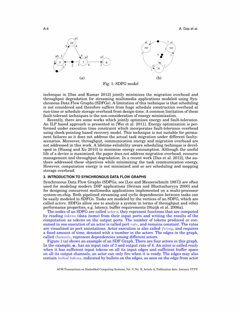
(b)Fig. 1: SDFG model
technique in [Das and Kumar 2012] jointly minimizes the migration overhead andthroughput degradation for streaming multimedia applications modeled using Syn-chronous Data Flow Graphs (SDFGs). A limitation of this technique is that schedulingis not considered and therefore suffers from huge schedule construction overhead atrun-time or schedule storage overhead from design-time. A common limitation of thesefault-tolerant techniques is the non-consideration of energy minimization.
Recently, there are some works which jointly optimizes energy and fault-tolerance.An ILP based approach is presented in [Wei et al. 2011]. Energy optimization is per-formed under execution time constraint which incorporates fault-tolerance overheadusing check-pointing based recovery model. This technique is not suitable for perma-nent failures as it does not address the actual task migration under different faulty-scenarios. Moreover, throughput, communication energy and migration overhead arenot addressed in this work. A lifetime-reliability aware scheduling technique is devel-oped in [Huang and Xu 2010] to minimize energy consumption. Although the usefullife of a device is maximized, the paper does not address migration overhead, resourcemanagement and throughput degradation. In a recent work [Das et al. 2012], the au-thors addressed these objectives while minimizing the task communication energy.However, computation energy is not minimized and so are scheduling and mappingstorage overhead.3. INTRODUCTION TO SYNCHRONOUS DATA FLOW GRAPHSSynchronous Data Flow Graphs (SDFGs, see [Lee and Messerschmitt 1987]) are oftenused for modeling modern DSP applications [Sriram and Bhattacharyya 2000] andfor designing concurrent multimedia applications implemented on a multi-processorsystem-on-chip. Both pipelined streaming and cyclic dependencies between tasks canbe easily modeled in SDFGs. Tasks are modeled by the vertices of an SDFG, which arecalled actors. SDFGs allow one to analyze a system in terms of throughput and otherperformance properties, e.g. latency, buffer requirements [Stuijk et al. 2006a].
The nodes of an SDFG are called actors; they represent functions that are computedby reading tokens (data items) from their input ports and writing the results of thecomputation as tokens on the output ports. The number of tokens produced or con-sumed in one execution of an actor is called port rate, and remains constant. The ratesare visualized as port annotations. Actor execution is also called firing, and requiresa fixed amount of time, denoted with a number in the actors. The edges in the graph,called channels, represent dependencies among different actors.
Figure 1 (a) shows an example of an SDF Graph. There are four actors in this graph.In the example, a1 has an input rate of 3 and output rate of 4. An actor is called readywhen it has sufficient input tokens on all its input edges and sufficient buffer spaceon all its output channels; an actor can only fire when it is ready. The edges may alsocontain initial tokens, indicated by bullets on the edges, as seen on the edge from actor
ACM Transactions on Embedded Computing Systems, Vol. V, No. N, Article A, Publication date: January YYYY.
Energy-Aware Task Mapping and Scheduling for Reliable Embedded Computing Systems A:5
a2 to a0 in Figure 1 (a). A set Ports of ports is assumed and with each port p ∈ Ports,a finite rate Rate(p) ∈ N \ 0 is associated. Formally an SDFG is defined as follows.
DEFINITION 1. (ACTOR) An actor ai is a tuple (Ii, Oi, Ni, µi) consisting of a set Ii(⊆ Ports) of input ports, a set Oi (⊆ Ports) of output ports with Ii ∩ Oi = ∅, Ni is theset of execution cycles of ai and µi is its state space (program and data memory). Theexecution cycle Ni is a set nil | 1 ≤ l ≤ h, representing the CPU cycles needed to executeactor ai on core type l. For homogeneous systems, h = 1 and therefore execution cycles ofan actor on all cores are the same.
DEFINITION 2. (SDFG) An SDFG is a directed graph Gapp = (A,C) consisting ofa finite set A of actors and a finite set C ⊆ Ports2 of channels. The source of channelchji ∈ C is an output port of actor ai, the destination is an input port of actor aj . Allports of all actors are connected to precisely one channel, and all channels are connectedto ports of some actor. The source and the destination port of channel chji are denoted bySrcP (chji ) and DstP (chji ) respectively. The channels connected to the input and outputports of an actor ai are denoted by InC(ai) and OutC(ai) respectively.
Before an actor ai starts its firing, it requires Rate(qi) tokens from all (p, qi) ∈InC(ai). When the actor completes execution, it produces Rate(pi) tokens on every(pi, q) ∈ OutC(ai). One of the most interesting properties of SDFGs relevant to thispaper is throughput. Throughput is defined as the inverse of the long term period, i.e.the average time needed for one iteration of the application. (An iteration is defined asthe minimum non-zero execution such that the original state of the graph is obtained.)This is the performance parameter used in this paper. The following properties of anSDF graph are defined.
DEFINITION 3. (REPETITION VECTOR) Repetition Vector Rpt of an SDFG Gapp =(A,C) is defined as the vector specifying the number of times actors in A are executedfor one iteration of SDFG Gapp.
For example, in Figure 1 (a), Rpt[a0 a1 a2 a3] = [1 1 1 2].
DEFINITION 4. (APPLICATION PERIOD) Application Period Per(A) is defined as thetime SDFG Gapp = (A,C) takes to complete one iteration on average.
The amount of data communicated from actor ai to actor aj is given by
dij = Rpt[ai] ∗Rate(SrcP (chji )) ∗ sze (1)
where sze is the size of a token in bits. The total amount of data communicatedbetween actors ai and aj is dij + dji.
The period of an SDFG can be computed by analyzing the maximum cycle mean(MCM) of an equivalent homogeneous SDFG (HSDFG). The period thus computedgives the minimum period possible with infinite hardware resources e.g. buffer space.If worst-case execution time estimates of each actor are used, the performance at run-time is guaranteed to meet the analyzed throughput. For multiple applications withsoft real-time constraint, an iterative approach similar to [Kumar et al. 2010] can beadopted to analyze and estimate throughput.
SDFGs allow buffer-sizes to be modeled as a back-edge with initial tokens. In suchcases, the number of tokens on that edge indicates the buffer-size available. Whenan actor writes data on a channel, the available size reduces; when the receiving actorconsumes this data, the available buffer increases. Figure 1 (b) shows such an example,where the buffer size of the channel from actor a1 to a2 is shown as two. Before a1 canbe executed, it has to check if enough buffer space is available. This is modeled byrequiring tokens from the back-edge to be consumed. Since it produces one token per
ACM Transactions on Embedded Computing Systems, Vol. V, No. N, Article A, Publication date: January YYYY.

A:6 A. Das et al.
c0 c1 c2
c3 c4 c5
c6 c7 c83
10
2
(a) (b)
ai aj
Floorplan
unaware mapping
ai
aj
c0
c8
Floorplan
aware mapping
ai
aj
c1
c5
(c)
Fig. 2: Conceptual architecture model
firing, one token from the back-edge is consumed, indicating reservation of one bufferspace on the output edge. On the consumption side, when a2 is executed, it frees twobuffer spaces, indicated by a release of two tokens on the back-edge. In the model, theoutput buffer space is claimed at the start of execution, and the input token space isreleased only at the end of firing. This ensures atomic execution of the actor.
Self-timed strategy is widely used for scheduling SDFGs on multiprocessor systems.In this technique, the exact firing of an actor on a core is determined at design-timeusing worst-case actor execution-time. The timing information is then discarded re-taining the assignment and ordering of the actors on each core. At run-time, actorsare fired in the same order as determined from design-time. Thus, unlike fully-staticschedules, a self-timed schedule is robust in capturing the dynamism in actor execu-tion time. In this respect the following lemmas are stated. For proof, readers are urgedto refer [Ghamarian et al. 2006].
LEMMA 1. For a consistent and strongly connected SDFG, the self-timed executionconsists of a transient phase followed by a periodic (steady-state) phase.
LEMMA 2. For a consistent and strongly connected SDFG, the throughput of anactor is given by the average firing of the actor per unit time in the periodic phase of theself-timed execution.
This paper focuses on streaming applications represented as SDFGs. However, thetechniques proposed are generic and applicable to both SDFGs and DAGs. Sectionsrequiring special treatment for either of them are appropriately highlighted.
4. PROBLEM FORMULATION4.1. Architecture modelThe architecture assumed for the target platform is shown in Figure 2 (a) with theprocessing cores interconnected in a mesh-based topology. Figure 2 (b) shows the cor-responding floorplan where different zones represent heterogeneity with the coreswithin each zone being homogeneous. In all existing reactive fault-tolerant studies,floorplanning of the cores is ignored i.e. heterogeneous cores are considered withouttheir actual coordinates. This can impact application communication energy as shownin Figure 2 (c). Here, actors ai and aj requires core type 0 and 1 respectively. Floorplan-unaware and floorplan-aware mapping examples are provided in two tables as shownin the figure. Clearly, floorplan-unaware mapping can lead to higher data communica-tion energy (data communicated over 4 hops between c0 and c8 as compared to 2 hopsbetween c1 and c5 in floorplan-aware mapping).
An architecture is represented as a graph Garc = (Varc, Earc), where Varc is the set ofnodes representing cores of the architecture and Earc is the set of edges representingcommunication channels among the cores. Each core cj ∈ Varc is a tuple 〈hj , Fj〉, wherehj represents the heterogeneity type of the core and Fj is the set ωjk of frequenciessupported on the core.
ACM Transactions on Embedded Computing Systems, Vol. V, No. N, Article A, Publication date: January YYYY.

Energy-Aware Task Mapping and Scheduling for Reliable Embedded Computing Systems A:7
4.2. Mapping representationFor ease of representation, the following notations are defined.
narc number of cores of the architecture i.e. narc = |Varc|napp number of actors of the given application i.e. napp = |A|Mn mapping of Gapp on Garc with n cores where n ≤ narcΦ(i) core on which actor ai is mapped in mapping Mn
Ω(i) frequency assigned to actor ai
Ψ(j) set of actors mapped to core cj
sf Fault scenario with f faulty cores = 〈ci1 , ci2 , · · · , cif 〉The mapping Mn is a 2× napp matrix as shown below.
Mn =
(Φ(1) Φ(2) · · · Φ(napp)Ω(1) Ω(2) · · · Ω(napp)
)The core assignment for the actors of the mapping Mn are indexed by Mn.Φ[1 : napp].
Here n is the number of cores used for the mapping and is equal to the number ofunique elements in the set Mn.Φ(1),Mn.Φ(2), · · · ,Mn.Φ(napp). The frequency assign-ment for the actors are indexed as Mn.Ω[1 : napp].
An ID is assigned to each mapping Mn as calculated in Equation 2.
mID(Mn) =
napp∑j=1
Mn.Φ(j) ∗ (narc)j (2)
Clearly, every mapping can be uniquely represented using this linearization tech-nique. For the ease of problem formulation a variable xijk is defined as follows
xijk =
1 if actor ai is mapped on core cj at frequency ωk0 otherwise (3)
4.3. Computation energy modeling of an applicationThe total computation power of an application is given as the sum of the dynamic andthe leakage power. The focus of this research is on reduction of dynamic power andhence is orthogonal to any leakage power reduction techniques. The dynamic powerof a circuit is given by Equation 4 where β is the activity factor, ω is the frequencyof operation, Ceff is the effective load capacitance and Vdd is the supply voltage. Thefrequency of operation is related to the supply voltage according to the α-Sakurai lawas given in equation 6, where K is a constant, α is a process-dependent parameter thatmodels velocity saturation and Vt is the CMOS threshold voltage.
P = β ∗ ω ∗ Ceff ∗ V 2dd (4)
ω = K ∗(Vdd − Vt)α
Vdd(5)
As established in [Meijer and de Gyvez 2008], for 65nm low power CMOS, the fre-quency scales linearly with supply voltage. Equation 5 can be rewritten as
ω ∝ Vdd (6)
The computation energy of an SDFG is given by Ecomp = Etrcomp +Niter ∗Ess
comp whereEtr
comp is the actor computation energy in the transient phase of the schedule, Esscomp is
the actor computation energy per iteration of the steady state phase and Niter is thenumber of iterations of the steady state phase. Usually, the number of steady stateiterations (i.e. Niter) is a large number (can be regarded as periodic decoding of everyframe for a video application) and hence for all practical purposes, the computation
ACM Transactions on Embedded Computing Systems, Vol. V, No. N, Article A, Publication date: January YYYY.

A:8 A. Das et al.
energy of the steady state phase dominates over that in the transient phase. Similarreasoning applies for actor communication energy. Throughout the rest of this paper,computation (or communication) energy implies computation (or communication) en-ergy of the steady state phase per iteration.
Denoting tijk as the execution time of the actor ai on core cj operating at frequencyωk, the dynamic energy consumption is given by Equation 7 where Rpt[ai] is the num-ber of firings of actor ai per steady state iteration of the SDFG.
eijk = P ∗ tijk ∗Rpt[ai] = β ∗ ωk ∗ Ceff ∗ V 2dd ∗ tijk ∗Rpt[ai] (7)
The execution time of an actor can be expressed in terms of its execution cycles i.e.tijk =
nij
ωk. Substituting this in Equation 7 and using Equations 4 and 6 yields
eijk = α ∗ Ceff ∗ V 2dd ∗ nij ∗Rpt[ai] ≈ K
′ ∗ ω2k ∗ nij ∗Rpt[ai] (8)
where K ′ is a constant. The computation energy of the application is given by2
Ecomp =∑i
∑j
∑k
eijk ∗ xijk (9)
4.4. Communication energy modeling of applicationsCommunication energy modeling for NoC-based MPSoCs has received significant at-tention in recent years. In [Ye et al. 2003], bit energy (Ebit) is defined as the energyconsumed in transmitting one bit of data through the routers and links of a NoC.
Ebit = ESbit+ ELbit
(10)
where ESbitand ELbit
are the energy consumed in the switch and the link respec-tively. The energy per bit consumed in transferring data between cores cp and cq, sit-uated nhops(p, q) away is given by Equation 11 according to [Hu and Marculescu 2004]where nhops(p, q) is the number of routers between cores cp and cq.
Ebit(p, q) =
nhops(p, q) ∗ ESbit
+ (nhops(p, q)− 1) ∗ ELbitif p 6= q
0 otherwise (11)
The communication energy (per iteration) is therefore given by Equation 12 whereΦ(i) and Φ(j) are the cores where actors ai and aj are mapped respectively.
Ecomm =∑
∀ai,aj∈A
dij ∗ Ebit(Φ(i),Φ(j)) (12)
4.5. Migration overhead modeling of applicationMigration overhead associated with moving from one mapping to another is governedby two quantities – the state space of the actors(s) participating in the migration pro-cess and the distance (hops) through which the state space is migrated3. It is assumedthat a given multiprocessor system consists of one or more task migration modules(TMMs) which can access the memory of a core without interfering its operation. Forthese systems, state space of an actor (mapped to a faulty core) can be recovered andhence migrated to some other core where the actor is mapped post fault occurrence.For multiprocessor systems without TMM(s), task migration involves migrating thestate space of an actor from the main memory to the new core where it is mapped.
2The proposed technique deals with scheduling-based energy minimization of an application and is orthog-onal to circuit level energy minimization techniques for the NoC (e.g. at switch fabric or network interface)or the processing cores (e.g. clock gating/power gating).3The state space of an actor consists of the the data memory and the pre-compiled object code for the hdifferent core types.
ACM Transactions on Embedded Computing Systems, Vol. V, No. N, Article A, Publication date: January YYYY.

Energy-Aware Task Mapping and Scheduling for Reliable Embedded Computing Systems A:9
Run-Time
Design-Time
start
Construct Initial
Mapping
Generate Mapping
with f less Tiles
Is throughput
met?
NO
Is f = F?
Yes
f=f+1
startConstruct
Initial Mapping
Generate f-fault tolerant mappings Is f = F?
f=f+1 No
mappingfault
.
...
Encode Mapping
start
endYes
Continue Operation
Is core faulty?
No
Decode Mapping
Yes
Task Migration
Determine fault
scenario
177980034521
201094-5..
.
.
Fig. 3: Design Methodology
To better couple with the computation and the communication energy, the migrationoverhead is represented as energy and is termed as migration energy. Let ai be an ac-tor mapped on core cj . Denoting ck as the core on which the actor ai is migrated aftercore cj becomes faulty, the migration energy is calculated according to Equation 13.
MigEnergy(j → k) =∑
∀ai∈Ψ(j)
µi ∗ Ebit(j, k) (13)
The migration energy constitutes a very small fraction of the overall energy con-sumption as established in Section 7.5. Unless otherwise stated, the migration energyis ignored for most of the experiments.
5. DESIGN METHODOLOGYThe fault-tolerant task mapping methodology consists of two phases – analysis of ap-plications at design-time and execution at run-time. The focus of this research is onthe design-time analysis; however, for the sake of completeness, a brief overview isprovided on how to use the design-time analysis results at run-time.
The fault-tolerant task mapping methodology is outlined in Figure 3. For everyfault-scenario with f faulty cores, an optimal mapping is generated which satisfiesthe throughput requirement and results in minimum energy overhead. These map-pings are encoded by the Encode Mapping block (according to Equation 2) and storedin memory. At run-time, an application is executed until faults occur. On detectionof a fault4, the corresponding fault-scenario is identified and the encoded mapping isfetched from the memory. This mapping is then decoded by the Decode Mapping blockand forwarded to the Task Migration block where actual migration is performed5.
The rest of this section is organized as follows. In Subsection 5.1 the fault-tolerantmapping generation technique is highlighted. An essential component of this is theminimum energy mapping generation which is described in Subsection 5.2. Finally inSubsection 5.3, a technique is proposed to select an initial mapping which minimizesapplication computation and communication energy.
4Our research is orthogonal to any fault-detection mechanism5It is to be noted that, mappings and schedules determined at design-time for different fault-scenariossatisfy an application throughput requirement. By enforcing these mappings and schedules at run-timepost fault occurrences, throughput is guaranteed for the application under all processor fault-scenarios.
ACM Transactions on Embedded Computing Systems, Vol. V, No. N, Article A, Publication date: January YYYY.
A:10 A. Das et al.
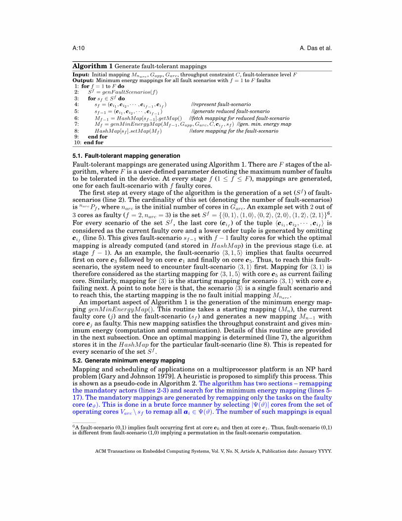
Algorithm 1 Generate fault-tolerant mappingsInput: Initial mapping Mnarc , Gapp, Garc, throughput constraint C, fault-tolerance level FOutput: Minimum energy mappings for all fault scenarios with f = 1 to F faults1: for f = 1 to F do2: Sf = genFaultScenarios(f)3: for sf ∈ Sf do4: sf = (ci1 , ci2 , · · · , cif−1
, cif ) //represent fault-scenario5: sf−1 = (ci1 , ci2 , · · · , cif−1
) //generate reduced fault-scenario6: Mf−1 = HashMap[sf−1].getMap() //fetch mapping for reduced fault-scenario7: Mf = genMinEnergyMap(Mf−1, Gapp, Garc, C, cif , sf ) //gen. min. energy map8: HashMap[sf ].setMap(Mf ) //store mapping for the fault-scenario9: end for10: end for
5.1. Fault-tolerant mapping generationFault-tolerant mappings are generated using Algorithm 1. There are F stages of the al-gorithm, where F is a user-defined parameter denoting the maximum number of faultsto be tolerated in the device. At every stage f (1 ≤ f ≤ F ), mappings are generated,one for each fault-scenario with f faulty cores.
The first step at every stage of the algorithm is the generation of a set (Sf ) of fault-scenarios (line 2). The cardinality of this set (denoting the number of fault-scenarios)is narcPf , where narc is the initial number of cores in Garc. An example set with 2 out of3 cores as faulty (f = 2, narc = 3) is the set Sf = 〈0, 1〉, 〈1, 0〉, 〈0, 2〉, 〈2, 0〉, 〈1, 2〉, 〈2, 1〉6.For every scenario of the set Sf , the last core (cif ) of the tuple 〈ci1 , ci2 , · · · , cif 〉 isconsidered as the current faulty core and a lower order tuple is generated by omittingcif (line 5). This gives fault-scenario sf−1 with f − 1 faulty cores for which the optimalmapping is already computed (and stored in HashMap) in the previous stage (i.e. atstage f − 1). As an example, the fault-scenario 〈3, 1, 5〉 implies that faults occurredfirst on core c3 followed by on core c1 and finally on core c5. Thus, to reach this fault-scenario, the system need to encounter fault-scenario 〈3, 1〉 first. Mapping for 〈3, 1〉 istherefore considered as the starting mapping for 〈3, 1, 5〉 with core c5 as current failingcore. Similarly, mapping for 〈3〉 is the starting mapping for scenario 〈3, 1〉 with core c1
failing next. A point to note here is that, the scenario 〈3〉 is a single fault scenario andto reach this, the starting mapping is the no fault initial mapping Mnarc
.An important aspect of Algorithm 1 is the generation of the minimum energy map-
ping genMinEnergyMap(). This routine takes a starting mapping (Mn), the currentfaulty core (j) and the fault-scenario (sf ) and generates a new mapping Mn−1 withcore cj as faulty. This new mapping satisfies the throughput constraint and gives min-imum energy (computation and communication). Details of this routine are providedin the next subsection. Once an optimal mapping is determined (line 7), the algorithmstores it in the HashMap for the particular fault-scenario (line 8). This is repeated forevery scenario of the set Sf .5.2. Generate minimum energy mappingMapping and scheduling of applications on a multiprocessor platform is an NP hardproblem [Gary and Johnson 1979]. A heuristic is proposed to simplify this process. Thisis shown as a pseudo-code in Algorithm 2. The algorithm has two sections – remappingthe mandatory actors (lines 2-3) and search for the minimum energy mapping (lines 5-17). The mandatory mappings are generated by remapping only the tasks on the faultycore (cϑ). This is done in a brute force manner by selecting |Ψ(ϑ)| cores from the set ofoperating cores Varc \ sf to remap all ai ∈ Ψ(ϑ). The number of such mappings is equal
6A fault-scenario (0,1) implies fault occurring first at core c0 and then at core c1. Thus, fault-scenario (0,1)is different from fault-scenario (1,0) implying a permutation in the fault-scenario computation.
ACM Transactions on Embedded Computing Systems, Vol. V, No. N, Article A, Publication date: January YYYY.

Energy-Aware Task Mapping and Scheduling for Reliable Embedded Computing Systems A:11
Algorithm 2 GenMinEnergyMap(): Energy aware mappingInput: Mapping Mn, graphs Gapp and Garc, throughput constraint C, fault ID ϑ and the fault-scenario sfOutput: New mapping Mn−1
1: //mandatory section: move actors from faulty core to other operating cores2: Γϑ = Set of mappings generated from Mn by remapping all ai ∈ Ψ(ϑ) to some cj ∈ Varc \ sf3: sort(Γϑ) in ascending order of communication energy4: //performance section: remap for minimum energy satisfying throughput5: numIter = 0; Mbest = Mt = Γϑ[numIter]; Ebest = calcEnergy(Mt)6: while numIter ≤ maxMap do7: [ai cj ωk] = RemapActor(Mt, Gapp, Garc, C, sf )8: if ai 6= ∅ then9: Mt.Φ(ai) = cj ; Mt.Ω(ai) = ωk10: else11: E = calcEnergy(Mt)12: if E < Ebest then13: Mbest = Mt; Ebest = E14: end if15: numIter + +; Mt = Γϑ[numIter]16: end if17: end while18: Return Mn−1 = Mbest
Algorithm 3 RemapActor(): Remap actors to minimize energyInput: Mapping Mi, graphs Gapp and Garc, throughput constraint C, fault-scenario sfOutput: Determine an actor to be remapped, the corresponding core and frequency1: Ei := calcEnergy(Mi); Ti = SDF 3
M (Mi); Gbest = 0; abest = ∅; cbest = ∅; ωbest = ∅2: for all ai ∈ Vapp do3: for all cj ∈ Varc \ sf do4: for all ωk ∈ Fj do5: M = Mi; M.φ(ai) = cj ; M.Ω(ai) = ωk; T = SDF 3
M (M); E = calcEnergy(M)6: if ((T ≥ C) && (E < Ei)) then7: G = Ei−E
T−Ti
8: if G > Gbest then Gbest = G; abest = ai; cbest = cj ; ωbest = ωk9: end if10: end for11: end for12: end for13: return [abest cbest ωbest]
to the number of ways of choosing a sample of |Ψ(ϑ)| balls with replacement from a setof |Varc \sf | balls. This is equal to |Varc \sf ||Ψ(ϑ)|. These mappings are pruned accordingto standard speed-up techniques (such as processor load [Jiashu et al. 2012]). Thesemappings are stored in an array Γϑ and is sorted in terms of communication energy(line 3). The maxMap best mappings are selected and used in the next stage. Thisnumber (maxMap) is equal to the number of iterations of the performance section anddetermines the termination (and hence the execution time) of the algorithm. It is to benoted that the communication energy based sorting provides better result (less energy)than migration overhead or throughput-based mappings.
The performance section of the algorithm remaps one or more actors selectively todetermine the minimum energy. At each iteration, the starting mapping is one of themapping of the set Γϑ. The RemapActor() routine selects an actor to be remapped sat-isfying the throughput requirement. If the return set is non-empty (implying actorscan be remapped without violating the throughput constraint), the actor is remappedto a core at a frequency as determined by the RemapActor() routine (line 9). The pro-cess is continued as long as no actors can be found to be remapped without violatingthe throughput. When this happens (line 10), the total energy of the mapping is calcu-
ACM Transactions on Embedded Computing Systems, Vol. V, No. N, Article A, Publication date: January YYYY.

A:12 A. Das et al.
Algorithm 4 Generate initial mappingInput: Gapp and GarcOutput: Minimum energy initial mapping Mnarc
1: Mt = SDF 3(Gapp, Garc);2: while true do3: [ai cj ωk] = RemapActor(Mt, Gapp, Garc, C, ∅)4: if ai 6= ∅ then5: Mt.Φ(ai) = cj ; Mt.Ω(ai) = ωk6: else7: break8: end if9: end while10: Return Mnarc = Mt
lated using the calcEnergy() routine which incorporates the two energy components7
– computation (Equation 9) and communication (Equation 12). If this is less than theminimum energy (Ebest) obtained so far, the best values are updated (line 13).
Algorithm 3 provides the pseudo-code for the RemapActor() subroutine which usesa gradient function to evaluate each actor to core assignment. The total energy andthe throughput is evaluated by moving every actor on every core at every frequencysupported (line 5). The SDF 3
M is the SDF 3 engine of [Stuijk et al. 2006b] modified tocompute the schedule and throughput from a given mapping8. If the throughput forthis move is greater than the throughput constraint and the energy is lower than theenergy of the initial mapping (Mi), the gradient is computed (line 7). If the gradient ishigher than the best gradient obtained so far, the best values are updated (line 8). Thebest actor, core and frequency values are returned.
5.3. Generate initial mappingIn the existing reactive fault-tolerant techniques, the starting mapping is determinedby searching the design space exhaustively. The computation time grows exponentiallywith the number of actors and cores. The problem becomes computationally infeasiblebeyond a certain number of cores and actors. The situation becomes even worse forheterogeneous architecture where the infeasibility point settles in at a much lowervalue of actors and cores. Algorithm 4 provides the pseudo-code for the initial mappinggeneration procedure of the proposed methodology. The initial mapping (Mt at line 1)is obtained by any deterministic task mapping and scheduling algorithm e.g. HEFTof [Topcuoglu et al. 2002] for DAGs or the unmodified SDF 3 engine for SDFGs. TheRemapActor() routine selects one actor to be remapped to a core at a frequency suchthat energy is minimized with least degradation of throughput. This follows the sameprinciple as the performance section of Algorithm 2 with the all working cores i.e.setting sf = ∅.6. SCHEDULINGAn important aspect of any application graph (cyclic and acyclic) is the scheduling ofactors on cores. There are different scheduling schemes proposed both for DAGs andSDFGs [Kwok and Ahmad 1999; Sriram and Bhattacharyya 2000; Davis and Burns2011; Damavandpeyma et al. 2012]. None of the existing fault-tolerant techniques ad-dress scheduling. If the run-time schedule is different from that used for analysis atdesign-time, the throughput obtained will be significantly different than what is guar-anteed at design-time. There are therefore two approaches to solve the problem.
7The migration energy component (Equation 13) is ignored as justified in Section 7.5.8For DAGs, multiple iterations are usually executed sequentially (in a non-overlapped fashion). For thesegraphs CPTO routine of [Goh et al. 2009] can be used to compute the performance measured as makespan.
ACM Transactions on Embedded Computing Systems, Vol. V, No. N, Article A, Publication date: January YYYY.

Energy-Aware Task Mapping and Scheduling for Reliable Embedded Computing Systems A:13
a0 a1 a2 a3 a4 a5 a6 a7
0 0 3 0 1 2 3 1Processor
Actors
a2 a0 a3 a4 a5 a7 a1 a1 a7 a2 a4 a6
Initial (uni-processor) steady-state schedule
a2 a0 a3 a5 a5 a7 a1 a1 a7 a2 a4 a6
Initial (uni-processor) transient schedule
a0 a3 a2 a5
Processor 0a0 a1 a3
Transient Schedule
Processor 1a4 a7
Processor 2a5
Processor 3a2 a6
Processor 0a0 a1 a3Actor Mapping
a0 a3 a1Constructed Schedule a1
Processor 1a4 a7Actor Mapping
a4 a7 a7Constructed Schedule a4
Processor 2a5Actor Mapping
a5Constructed Schedule
Processor 3a2 a6Actor Mapping
a2 a2 a6Constructed Schedule
2 2 2
1 2
3
3 1
Steady-state Schedule
a5
a5
Fig. 4: Schedule construction from an initial schedule and actor allocation
— store the actor mapping and scheduling for all fault-scenarios and for all applicationsfrom design-time (storage-based)
— constructs the schedule at run-time based on the mappings stored from the design-time (construction-based)
The former is associated with high storage overhead and the latter with longer exe-cution time. Both storage and execution time overhead are crucial for streaming appli-cations. A self-timed execution based scheduling is proposed to solve the two problems.
Based on the basic properties of self-timed scheduling, it can be proven that if theschedule of actors on a uni-processor system is used to derive the schedules for amultiprocessor system maintaining the actor firing order, the resultant multiproces-sor schedule will be free of deadlocks [Blazewicz 1976]. However, throughput obtainedusing this technique can be lower than the maximum throughput of a multiproces-sor schedule constructed independently. Thus, as long as this throughput deviation isbounded, the schedule for any processor can be easily constructed from the mapping ofactors to this processor and a given uni-processor schedule.
Figure 4 shows the operation of the proposed scheduling technique. The actor-processor mapping indicates that actors a0, a1 and a3 are mapped to processor 0. Theinitial steady-state schedule indicates that there are two instances of a1 and one eachfor actors a0 and a3 respectively. The steady-state order of actor firing on processor0 is determined from this initial schedule by retaining only the mapped actors. In asimilar way the steady-state schedules are constructed for all other processors. Thetransient part of the schedules are constructed from the given initial uni-processortransient schedule by retaining the mapped actors. However, the only difference of thetransient phase schedule construction with the steady-state phase is that for the tran-sient phase, the number of actors firing is important and not the exact order. This isindicated by a number against each actor for each processor as shown in the figure.
During the steady-state operation, every processor maintains counts of the numberof remaining steady-state firings for the actors mapped to the core. These numbers areupdated when an actor completes its execution. When a fault occurs, the mapped actorson the faulty core are moved to new location(s) (cores) along with the remaining firingcount. On such cores, which have at least one incoming migrated actor, all actors are
ACM Transactions on Embedded Computing Systems, Vol. V, No. N, Article A, Publication date: January YYYY.

A:14 A. Das et al.
Algorithm 5 Schedule generationInput: Gapp, Ns, ∆Output: Schedule for all fault-scenarios1: forall f ∈ [1 · · ·F ] do Sf = genFaultScenarios(f)2: maxIter = |Sf |; sDB = constructUniSchedule(Gapp, Ns); sDBt = sDB
3: while Sf 6= ∅ do4: //compute rank of each initial schedule5: for all schedule li ∈ sDB do6: Initialize count = 07: for all sf ∈ Sf do8: Mt = HashMap[sf ].getMap(); P = SDF 3
MS(Mt, li)9: if P ≥ C then count+ +10: end for11: li.rank = count12: end for13: lmin = getHighestRankSchedule(sDB)14: for all sf ∈ Sf do15: Mt = HashMap[sf ].getMap(); P = SDF 3
MS(Mt, li)16: if P ≥ C then17: Sche[sf ] = lmin; Sf .eliminate(sf )18: end if19: end for20: numIter + +21: //avoid stuck in loop22: if numIter > maxIter then numIter = 0; C = C −∆23: end while
allowed to execute in a self-timed manner to finish the remaining firing counts of thecurrent pending iteration (similar to initial transient phase). From the subsequent it-eration onwards, the steady-state order can be enforced for the moved actors. This willprevent the application from going into deadlock when a fault occurs. In determiningthe actor counting in the steady-state iterations, schedule minimization is disabled. Asan example, in Figure 4, the steady state schedule constructed for processor 2 consistsof two executions of actor a5 as opposed to one in the otherwise minimized schedule.
Algorithm 5 provides the pseudo-code for the modified self-timed execution tech-nique for generating the steady-state schedule. The first step towards this is theconstruction of uni-processor schedules. A list scheduling technique is adopted forthis purpose along with several algorithms for tie-breaking e.g. ETF (earliest taskfirst), DLS (dynamic level scheduling) etc. These algorithms are implemented in theconstructUniSchedule() routine. The number of uni-processor schedules constructedusing this routine is a user-defined parameter Ns. These schedules are stored in adatabase in memory (sDB). The list of fault-scenarios possible with F faults are alsolisted in the set Sf . Using each of the uni-processor schedules as the initial schedule,throughput is computed for the given application for all fault-scenario mappings. TheSDF 3
MS computes the throughput of a mapping using a given uni-processor schedule.For each uni-processor schedule from sDB, a count (termed as rank) is determined.
The value indicates the number of fault-scenarios for which the throughput constraintis satisfied with this as the initial schedule. The schedule with the highest rank isselected and assigned as the initial schedule for the successful fault-scenarios. A fault-scenario is termed successful with respect to a schedule if the throughput constraint issatisfied with the given schedule. The successful candidates and the selected scheduleare discarded from the list of fault-scenarios (Sf ) and schedule database (sDB) respec-tively and stored in a 2-Dimensional database FSche. The process is repeated as longas the set Sf is non-empty.
The limited set of uni-processor schedules does not guarantee throughput satisfia-bility for all fault-scenarios. If such a fault-scenario exists, Sf is never ∅ causing the
ACM Transactions on Embedded Computing Systems, Vol. V, No. N, Article A, Publication date: January YYYY.

Energy-Aware Task Mapping and Scheduling for Reliable Embedded Computing Systems A:15
algorithm to be stuck in a loop. To avoid such situations, a check is performed (line 22)to limit the number of iterations. The maximum number of iterations is upper boundedby the number of fault-scenarios. Every time the iteration count reaches this value, thethroughput constraint is decremented by a small quantity (∆). The granularity of thisis based on the execution time and solution quality trade-off.
7. RESULTSExperiments are conducted on synthetic and real application graphs on Intel Xeon2.4 GHz server running Linux. Fifty synthetic applications are generated with thenumber of actors in each application selected randomly from the range 8 to 100. Ad-ditionally, fifteen real applications are considered with seven from streaming and theremaining eight from non-streaming domain. The streaming applications are obtainedfrom the benchmarks provided in the SDF 3 tool [Stuijk et al. 2006b]. These are H.263Encoder, H.263 Decoder, H.264 Encoder, MP3 Decoder, MPEG4 Decoder, JPEG De-coder and Sample Rate Converter. The non-streaming application graphs consideredare FFT, Romberg Integration and VOPD from [Bertozzi et al. 2005] and one appli-cation each from automotive, consumer, networking, telecom and office automationbenchmark suite [Dick 2013]. These applications are executed on MPSoC architec-tures consisting of 4 to 25 cores arranged in a mesh-based topology. A heterogeneityof 3 (h = 3) is assumed for the cores i.e. each core can be of one of the three differenttypes. Four frequency levels are assumed for each core. Although, these parametersare assumed for simplicity, the algorithms can be trivially applied to any heterogene-ity levels with any supported frequencies. The bit energy (Ebit) for modeling commu-nication energy of an application is calculated using expressions provided in [Ye et al.2003] for packet-based NoC with Batcher-Banyan switch fabric using 65nm technologyparameters from [Zhao and Cao 2007].
All algorithms developed in this work are coded in C++. Since this is the first workon reactive fault-tolerance considering throughput, computation and communicationenergy optimization jointly, there are no existing works for comparison. However, re-sults of this work are compared with some of the existing reactive fault-tolerant tech-niques such as the throughput maximization technique of [Lee et al. 2010] (referredto as TMax), the migration overhead minimization technique of [Yang and Orailoglu2007] (referred as OMin), the energy minimization technique of [Hu and Marculescu2004] (referred as EMin), the throughput constrained migration overhead minimiza-tion technique of [Das and Kumar 2012] (referred as TConOMin) and the throughputconstrained communication energy minimization technique of [Das et al. 2012] (re-ferred as TConCMin). The technique proposed here minimizes total energy (compu-tation and communication energy) with throughput as a constraint and is referred asTConEMin. The objective of these comparisons is to establish the fact that the existingtechniques when applied to MPSoC can lead to sub-optimal results in terms of energyconsumption and throughput per unit energy metric.
7.1. Complexity analysis of algorithmsThere are three algorithms proposed in this paper – fault-tolerant mapping genera-tion algorithm (Algorithms 1, 2 and 3), the initial mapping generation algorithm (Al-gorithm 4) and the schedule generation algorithm (Algorithm 5). The complexity ofAlgorithm 1 is calculated as follows. The number of iterations of the algorithm is de-termined by the number of fault scenarios with F faults. This is given by Equation 14.
nFS =
F∑f=1
narcPf (14)
ACM Transactions on Embedded Computing Systems, Vol. V, No. N, Article A, Publication date: January YYYY.

A:16 A. Das et al.
At each iteration, the genMinEnergyMap algorithm is invoked. The overall com-plexity of Algorithm 1 is given by Equation 15 where O(C2) is the complexity ofgenMinEnergyMap (Algorithm 2).
O(C1) = O (nFS ∗O(genMinEnergyMap)) = O(nFS ∗O(C2)) (15)
The complexity of Algorithm 2 is governed by two factors – parameter maxMap andthe routine RemapActor(). Core and frequency assignments for an actors are accom-plished in constant time. Assuming the RemapActor() routine to be executed η timeson average for each value of numIter, the complexity of Algorithm 2 is
O(C2) = maxMap ∗ η ∗O(RemapActor) (16)
The RemapActor() routine remaps each actor on each functional core at each fre-quency to determine if the throughput constraint is satisfied and the energy is lowerthan the minimum energy obtained so far. If actor assignment operations take unittime and the complexity of the SDF 3
M engine is denoted by O(SDF 3M ), the overall com-
plexity of Algorithm 3 is given by Equation 17 where nfreq is the average number offrequency levels supported on a core.
O(RemapTask) = O(C3) = O(napp ∗ narc ∗ nfreq ∗O(SDF 3M )) (17)
Combining Equations 15, 16 and 17, the complexity of the fault-tolerant mappinggeneration algorithm is given by equation 18.
O(C1) = O(nFS ∗maxMap ∗ η ∗ napp ∗ narc ∗ nfreq ∗O(SDF 3M )) (18)
The complexity of the schedule generation algorithm (Algorithm 5) is calculated asfollows. The rank computation for all the uni-processor schedules can be performed inO(ns ∗ nFS) time where ns is the number of uni-processor schedules constructed andnFS is the number of fault-scenarios. The highest throughput rank can be selected inO(ns) and lines 15-19 can be performed in O(nFS ∗O(SDF 3
MS)). Finally, the outer whileloop (lines 3-23) is repeated nFS times in the worst case. Combining,
O(C5) = O(nFS ∗ [ns ∗ nFS + ns + nFS ∗O(SDF 3M )]) = O(n2
FS ∗O(SDF 3M ))
7.2. Selection of initial mappingFigure 5 plots the throughput and the energy performance of the proposed techniquein comparison with the three prior research works on reactive fault-tolerance. Thestarting mapping selection criteria for these works are highest throughput (TMaxof [Lee et al. 2010]), migration overhead minimization with throughput constraint(TConOMin of [Das and Kumar 2012]) and communication energy minimization withthroughput constraint (TConCMin of [Das et al. 2012]) respectively. Additionally, to de-termine the energy overhead incurred in considering throughput in the optimizationprocess, the proposed technique is also compared with the minimum energy startingmapping (EMin of [Hu and Marculescu 2004]).
Figure 5(a) plots the normalized total energy consumption per iteration of 8 real-life applications for the existing and the proposed techniques. The energy values arenormalized with respect to those obtained using TMax. As can be seen from the figure,the energy consumption of the proposed technique (TConEMin) is the least amongall the existing reactive fault-tolerant techniques. This trend is also true for all the42 remaining applications considered (not shown explicitly here). On average, for allthe applications, TConEMin achieves 30%, 25% and 16% less energy as compared tothe TMax, TConOMin and TConCMin respectively. The energy savings with respectto TConCMin is lower as compared to the other two techniques because TConCMinminimizes communication energy component of the total energy while the other two
ACM Transactions on Embedded Computing Systems, Vol. V, No. N, Article A, Publication date: January YYYY.

Energy-Aware Task Mapping and Scheduling for Reliable Embedded Computing Systems A:17
MPEG4 Dec H.264 Enc MP3 Dec JPEG Dec Consumer Security Telecomm Networking0
0.1
0.2
0.3
0.4
0.5
0.6
0.7
0.8
0.9
1
Applications
Nor
mal
ized
Ene
rgy
a
MPEG4 Dec H.264 Enc MP3 Dec JPEG Dec Consumer Security Telecomm Networking0
0.1
0.2
0.3
0.4
0.5
0.6
0.7
0.8
0.9
1
ApplicationsN
orm
aliz
ed T
hrou
ghpu
t
b
TMax TConOMin TConCMin TConEMin (Proposed) EMin
Fig. 5: Energy and performance for different applications
Table I: Number of mappings in exhaustive search
Actors Homogeneous Heterogeneous1 core type 2 core types 3 core types
2 2 6 124 15 94 3096 203 2,430 12,3518 4,140 89,918 681,870
10 115,975 4,412,798 48,718,56914 190,899,322 20,732,504,062 461,101,962,108
techniques do not consider energy optimization. Finally, the TConEMin consumes 15%more energy than EMin which does not consider throughput degradation.
Figure 5(b) plots the normalized throughput of all the techniques. The throughputconstraint is shown by the dashed line in the figure. As previously indicated, the EMindoes not consider throughput degradation and therefore throughput constraint is vio-lated for most applications (a total of 45 out of all 50 applications).
Another aspect of the starting mapping generation algorithm is the execution time.The reactive fault-tolerant techniques in [Lee et al. 2010; Das and Kumar 2012; Daset al. 2012] search the design space exhaustively to select a starting mapping. Al-though this is solvable for homogeneous cores with limited number of actors and/orcores, the same becomes computationally infeasible even for small problem size as thecores become heterogeneous. Table I reports the growth in the size of the design space(number of mappings evaluated) as the number of actors scales. The number of coresin the table is same as the number of actors. If the SDF 3 engine takes an average 10µSto compute the schedule of a mapping, the design space exploration time for 14 actorson 14 cores with three types of heterogeneous cores is 54 days. The heuristic proposedin this paper solves the same problem in less than 2 hours.
ACM Transactions on Embedded Computing Systems, Vol. V, No. N, Article A, Publication date: January YYYY.

A:18 A. Das et al.
0 n1T n2T T
Single Fault
Double Fault
lifetime
0 ≤ n1, n2 ≤ 1
Fig. 6: Simulation environment
0 0.2 0.4 0.6 0.8 10.5
0.55
0.6
0.65
0.7
0.75
0.8
0.85
0.9
0.95
1
Single fault occurrence time
Nor
mal
ized
ene
rgy
a
(0.1, 0.2) (0.2, 0.5) (0.3, 0.7) (0.4, 0.5) (0.5, 0.9)0.5
0.55
0.6
0.65
0.7
0.75
0.8
0.85
0.9
0.95
1
Nor
mal
ized
ene
rgy
Double fault occurrence time
b
TMax TConOMin TConCMin TConEMin
Fig. 7: Lifetime energy consumption of MPSoC with single and double faults
7.3. Energy savings with core fault scenariosThis section introduces the energy savings obtained during the overall lifetime of anMPSoC as one or more permanent faults occur. Experiments are conducted with thesame set of applications (50 in total) and executed on an architecture with 2× 3 cores.The number of faults is restricted to 2. These are forced to occur after n1 ∗T and n2 ∗Tyears respectively from the start of the device operation, where T is the total lifetimeof the device and 0 ≤ n1, n2 ≤ 1. Figure 6 represents the simulation environment.During 0 to n1 ∗ T years, energy is consumed by the starting mapping i.e. the no-faultmapping obtained in Subsection 7.2; during n1 ∗ T years to n2 ∗ T years and n2 ∗ Tyears to T years, energy is consumed by single fault-tolerant and the double fault-tolerant mappings respectively. The cores affected by faults are selected randomly andthe results presented here is average of all single and double faults for all applications.
Figure 7(a) plots the result for single fault scenario i.e. assuming only single faultoccurs during the lifetime of the device. The average energy per iteration of the appli-cation is plotted with n1 varied from 0 to 1. A lower value of n1 implies a fault occursin the early life of the device while a higher value indicates faults occurring at laterstages. Since EMin does not consider fault scenarios, only reactive fault-tolerant tech-niques (with throughput consideration) are included for comparison.
As can be seen from this figure, the energy consumption of TMax and TConOMintechniques are comparable and is higher than that consumed by the other two tech-niques. This is due to the non-consideration of computation and communication energy
ACM Transactions on Embedded Computing Systems, Vol. V, No. N, Article A, Publication date: January YYYY.

Energy-Aware Task Mapping and Scheduling for Reliable Embedded Computing Systems A:19
Table II: Execution time (in secs) of existing and proposed technique
Actors
Homogeneous (1 core type) Heterogeneous (3 core types)Existing Proposed Existing Proposed
4 cores 9 cores 4 cores 9 cores 4 cores 9 cores 4 cores 9 cores4 110 1, 450 100 1, 210 150 2, 150 150 1, 900
8 630 6, 770 410 3, 100 1, 810 17, 440 720 5, 980
12 80, 100 − 1, 320 6, 600 2, 47, 000 − 2, 280 12, 700
16 − − 9, 700 10, 600 − − 16, 750 22, 400
for optimization. Although TConOMin minimizes migration overhead (energy), thisenergy is one time overhead (incurred during fault) and is negligible compared to thetotal energy consumed in the lifetime of the device. TConCMin considers communica-tion energy and throughput jointly and therefore the energy is lower than TMax andTConOMin by average 23% and 20% respectively. The proposed TConEMin minimizesthe total energy by achieving an average 22% savings as compared to TConCMin.
Figure 7(b) plots the result for double fault scenarios. A fault-coordinate (n1,n2)refers to the time for the first and the second fault occurrence respectively. Although,experiments are conducted for all values of the fault-coordinates, results for few of thecoordinates are plotted. Similar to the single fault results, the proposed TConEMinalso achieves 30% lower energy as compared to the existing techniques for MPSoCwith two faults. These results prove that considering energy in the mapping selectionfor fault-tolerance is crucial for the overall MPSoC energy consumption.
7.4. Execution time comparison of the proposed fault-tolerant algorithmAs established previously, all the prior fault-tolerant works search for a suitable map-ping exhaustively for different fault-scenarios. A dynamic programming is proposed in[Lee et al. 2010] to compute the minimum migration overhead incurred in moving froman initial mapping to the fault-scenario mapping. An ILP approach is proposed as analternative in [Das and Kumar 2012; Das et al. 2012] to compute the minimum migra-tion overhead. However, selection of the fault-tolerant mapping is based on exhaus-tive search. Although, dynamic programming and ILP are computationally feasiblefor small problem sizes, the bottleneck is in the exhaustive mapping selection process(which grows exponentially with the number of actors and cores) limiting their adapt-ability for large problem size and heterogeneous architectures. The work in this paperaddresses this problem by proposing a heuristic algorithm with worst case complexitygiven by Equation 18. Table II reports the execution time of the existing approachesin comparison with the proposed heuristic for homogeneous and heterogeneous archi-tecture with different actors and core count. For the existing approaches, the execu-tion time reported in the table includes mapping generation time, mapping evaluationtime (throughput computation) and the dynamic programming (or ILP) time for fault-tolerant mapping selection. For the proposed approach, the execution time is the sumof the execution time of Algorithms 1 and 4.
There are a few trends to be followed from this table. First of all, the executiontime on heterogeneous architecture is more than that on homogeneous architecturefor all actor-core combinations. This trend is same for the proposed approach as wellas the existing approaches. This is due to the fact that with core heterogeneity, theexecution time of an actor is different on different cores and therefore more actor-corecombinations are evaluated. Secondly, the execution time of the proposed approach iscomparable with that of the existing approaches for fewer actors (4 in the table) due tothe fewer number of exhaustive mappings. Third, as the number of actors increases,the number of actor-core combinations (mappings) grows exponentially leading to anexponential growth in the execution time for the existing approaches. Beyond 12 ac-
ACM Transactions on Embedded Computing Systems, Vol. V, No. N, Article A, Publication date: January YYYY.

A:20 A. Das et al.
Table III: Migration overhead performanceMigration Total Migration Overhead Extra Energy Iterations
Energy (nJ) Energy (nJ) Savings (nJ) Per Iteration (nJ) to recover
H.264 EncoderOMin 1.1× 10⁹ 7.2× 10⁵ 7× 10⁸ 3.2× 10⁵ 2, 188
TConOMin 1.7× 10⁹ 4.6× 10⁵ 1× 10⁸ 6× 10⁴ 1, 667
TConEMin 1.8× 10⁹ 4.0× 10⁵ – – –
MP3 DecoderOMin 7.0× 10⁸ 2.9× 10⁶ 1.7× 10⁹ 1.4× 10⁶ 1, 215
TConOMin 1.3× 10⁹ 2.0× 10⁶ 1.1× 10⁹ 5× 10⁵ 2, 200
TConEMin 2.4× 10⁹ 1.5× 10⁶ – – –
tors, these techniques fail to provide a solution due to the high memory requirement(to store the mappings) of the host CPU. The proposed technique scales well with thenumber of actors and cores. For 12 actors mapped on 4 cores of three different types,the proposed technique results in 100x reduction in execution time with less than 10%variation from the optimal solutions obtained by solving the Equations 9 and 12 di-rectly while satisfying the application throughput requirement. Further, the proposedtechnique achieves upto 15x reduction in execution time as compared to simulatedannealing based heuristic. Details are omitted for space limitations.7.5. Migration overhead performanceTable III reports the migration overhead (measured as energy) and total energy of twoexisting techniques (OMin and TConOMin) in comparison with the proposed techniquefor two different applications (H.264 Encoder and MP3 Decoder) with 5 and 14 actorson an MPSoC with 6 cores arranged in 2× 3. The core heterogeneity is fixed to 2. Theother existing techniques (TMax, EMin and TConCMin) are not included for compari-son as they do not optimize migration overhead. Columns 3 and 4 report the migrationoverhead incurred when faults occur and the average energy consumption per itera-tion of the application graph respectively. These numbers are average of single anddouble faults values. Column 5 reports the savings in migration overhead achievedby OMin and TConOMin with respect to the proposed TConEMin. Column 6 reportsthe extra energy (computation + communication) incurred in selecting the same twotechniques with respect to TConEMin.
As can be seen from the table, significant savings in migration overhead are possiblewith OMin technique. However, this technique is associated with energy penalty (col-umn 6). For application H.264 Encoder for example, the migration overhead savings inOMin is 7× 10⁸nJ while the energy penalty is 3.2× 10⁵nJ per iteration. As establishedpreviously, migration is one time overhead and energy is consumed in every iterationof the application graph (both pre- and post-fault occurrence). Therefore, the savingsin migration overhead is compensated in 7×10⁸
3.2×105 = 2, 188 iterations (≈ 146s with a500MHz clock at encoding rate of 15 frames per sec). This is shown in column 7 of thetable. Interpreting this in reverse manner, selecting TConEMin as the fault-toleranttechnique results in an extra migration overhead of 7 × 10⁸nJ which is amortized inthe next (post-fault) 2, 188 iterations of the application graph.
For most of the multimedia applications, actors are executed periodically. Examplesof these applications on a mobile phone include decoding of frames while playing videoand fetching emails from server. Typically, these applications are executed countablyinfinite times in the entire lifetime of the device. If N denotes the total iterations of adevice post-fault occurrence, then the first 2, 188 iterations will be used to recover themigration overhead loss while the remaining (N − 2188) iterations will fetch energysavings (3.2 × 10⁵nJ per iteration). As N → ∞, the energy savings obtained = (N −2188) × 3.2 × 105 ≈ N × 3.2 × 10⁵nJ . This substantial energy gain clearly justifies thenon-consideration of migration overhead in the fault-tolerant mapping selection.
ACM Transactions on Embedded Computing Systems, Vol. V, No. N, Article A, Publication date: January YYYY.

Energy-Aware Task Mapping and Scheduling for Reliable Embedded Computing Systems A:21
2 4 6 81.5
2
2.5
3
3.5
4
4.5
5
Number of cores
Thr
ough
put p
er u
nit e
nerg
y (it
erat
ions
/sec
/J)
H263 Decoder
TMax TConOMin TConCMin TConEMin
2 4 6 80
1
2
3
4
5
6
7
Number of cores
Thr
ough
put p
er u
nit e
nerg
y (it
erat
ions
/sec
/J)
H263 Encoder
2 4 6 80.5
1
1.5
2
2.5
3
Number of cores
Thr
ough
put p
er u
nit e
nerg
y (it
erat
ions
/sec
/J)
Sample Rate Converter
2 4 6 80.06
0.08
0.1
0.12
0.14
0.16
0.18
Number of cores
Thr
ough
put p
er u
nit e
nerg
y (it
erat
ions
/sec
/J)
MPEG Decoder
2 4 6 81
1.5
2
2.5
Number of cores
Thr
ough
put p
er u
nit e
nerg
y (it
erat
ions
/sec
/J)
Romberg Integration
2 4 6 8
0.3
0.32
0.34
0.36
0.38
0.4
Number of coresT
hrou
ghpu
t per
uni
t ene
rgy
(iter
atio
ns/s
ec/J
)
FFT
Fig. 8: Throughput-energy joint performance for real-life applications
7.6. Scalable throughput performanceStreaming multimedia applications can be broadly classified into two categories – ap-plications, those benefiting from scalable QoS and those requiring a fixed throughput.Majority of the streaming applications such as video encoding/decoding falls in the lat-ter category. The results of the previous sections are based on performance (through-put) as constraint. However, to signify the importance of the proposed technique forscalable throughput applications, a metric is defined (throughput per unit energy). Theproposed and the existing techniques are compared based on this metric (Figure 8).Experiments are conducted with a set of 6 real applications on an architecture withthe number of cores varying from 2 to 8. Core heterogeneity of the architectures is lim-ited to 2 as the existing techniques fail to provide a solution for the applications withhigher core heterogeneity. The results reported in the figure are average of all singleand double fault scenarios. A common trend from these plots is that for most applica-tions (except H.263 Encoder) the throughput per unit energy initially increases withthe number of cores. However, beyond a certain core count, the throughput per unitenergy decreases. This behavior is same for all the techniques i.e. TMax, TConOMin,TConCMin and TConEMin. As the number of cores increases, the throughput of anapplication increases. At the same time, the two energy components (computation andcommunication) also increase. For lower core count, the growth in throughput dom-inates causing an increase in the overall throughput per unit energy. As the corecount increases beyond 6 cores (4 cores for Romberg Integration and FFT), the en-ergy growth dominates over throughput growth and therefore the throughput per unitenergy drops. Although, H.263 Encoder shows a growth in throughput per unit en-
ACM Transactions on Embedded Computing Systems, Vol. V, No. N, Article A, Publication date: January YYYY.

A:22 A. Das et al.
4 6 8 10 12 140.6
0.65
0.7
0.75
0.8
0.85
0.9
0.95
1
Number of cores
Nor
mal
ized
Thr
ough
put
(a) Initial Schedule (S1)
(1)
(3)
(4)
(1−2)
(4−3)
(3−1)
4 6 8 10 12 140.6
0.65
0.7
0.75
0.8
0.85
0.9
0.95
1
Number of cores
Nor
mal
ized
Thr
ough
put
(b) Initial Schedule (S2)
(1)
(3)
(4)
(1−2)
(4−3)
(3−1)
4 6 8 10 12 140.6
0.65
0.7
0.75
0.8
0.85
0.9
0.95
1
Number of cores
Nor
mal
ized
Thr
ough
put
(c) Initial Schedule (S1, S
2)
(1)
(3)
(4)
(1−2)
(4−3)
(3−1)
2 4 6 8 100.5
0.6
0.7
0.8
0.9
1
1.1
Number of initial schedules
Nor
mal
ized
Thr
ough
put
(d) Throughput degradation for different applications
r(12)
r(16)
r(20)
MP3 Decoder
MPEG Decoder
Fig. 9: Normalized throughput using the proposed self-timed execution
ergy upto 8 cores, the drop-off point is observed for TConEMin with 16 cores. However,the results are omitted as the exhaustive search based existing techniques – TMax,TConOMin and TConCMin fail to give a solution for that value of core count.
As can be seen, the throughput per unit energy of TConEMin is the highest amongall existing techniques delivering on average 30% better throughput per unit energy.
7.7. Throughput performance of the proposed self-timed execution scheduleFigure 9 (a,b,c) plots the throughput obtained in the proposed self-timed executionbased scheduling technique for six fault-scenarios (3 single and 3 double) of applica-tion MP3 Decoder as the number of cores is varied from 4 to 14. There are two initialuni-processor schedules considered (Ns = 2). The multiprocessor throughput obtainedusing these uni-processor schedules are normalized with respect to the throughputobtained using the SDF 3 tool and are plotted in Figure 9 (a,b)
As can be seen from Figure 9 (a) (with initial schedule as S1), for all fault-scenarios,the normalized throughput decreases with increase in the number of cores. This isexpected as uni-processor schedule fails to capture the parallelism available with mul-tiple cores. Among the six fault-scenarios considered, the throughput degradation forfault-scenario (4) is maximum (≈ 30%), while for others this is less than 20%. Simi-larly, for Figure 9 (b) (corresponding to initial schedule S2), fault-scenarios (1) and (4-3) suffers the maximum throughput degradation of 25%. If the two schedules (S1 andS2) are considered to be available simultaneously and the one which gives the high-est throughput for a fault-scenario is selected as the initial schedule, the throughputdegradation can be bounded (predicted) at design time. This is shown in Figure 9 (c)where S1 is selected as the initial schedule for fault-scenarios (1) and (4-3) and S2
as the initial schedule for the remaining fault-scenarios. The maximum throughput
ACM Transactions on Embedded Computing Systems, Vol. V, No. N, Article A, Publication date: January YYYY.

Energy-Aware Task Mapping and Scheduling for Reliable Embedded Computing Systems A:23
Table IV: Schedule storage overhead and computation time
Parameters H.263 Encoder MP3 DecoderStorage Construction Proposed Storage Construction Proposedbased based based based
Mapping and schedule storage overhead (Kb) 892.1 68.6 68.6 1464 91.5 91.5Run-time schedule construction time (s) 0 0.42 0.027 0 3.06 0.035Design-time schedule construction time (s) 34.44 34.44 2.75 80 80 3.66
degradation obtained using this technique is 18%. Figure 9 (d) plots the throughputdegradation obtained as the number of initial schedules is increased from 2 to 10 forfive different applications. The results reported in this plot are the average of all singleand double fault-scenarios. As can be seen from this figure, the throughput degrada-tion decreases with an increase in the number of initial schedules. On average forall five applications considered, the throughput degradation is within 5% from thethroughput constructed using SDF 3 with 10 initial schedules. A point to note here isthat, choosing more initial schedules results in an increase in the storage complexity.Results indicate that Ns = 10 (i.e 10 initial schedules) offer the best trade-off withrespect to storage and throughput degradation.7.8. Schedule storage overhead and schedule computation time performanceTable IV reports the schedule storage overhead (in Kb) and the schedule computa-tion time using the proposed self-timed execution technique in comparison with thestorage-based and the construction-based techniques for two applications (H.263 En-coder and MP3 Decoder) with 5 and 14 actors on an architecture with 12 cores arrangedin 3 × 4. The results are reported for 3 fault-tolerant systems. The construction-basedand the proposed technique require storing the fault-tolerant mappings only while thestorage-based technique stores the schedule of actors on all cores and for all fault-scenarios alongside the fault-tolerant mappings.
The run-time storage construction overhead is 0 for the storage-based technique be-cause schedule needs to be fetched from a database9. The construction-based techniqueresults in a execution time of 0.4s. The construction time increases exponentially withthe number of actors and/or cores (column 3 & 6). This large schedule constructiontime can potentially lead to deadline violations. The proposed technique results in alinear growth of execution-time and is scalable with the number of actors and cores.
Finally, the reported execution-time of the design-time analysis phase for thestorage-based and the construction-based techniques involve construction of the sched-ule for all the fault-scenarios. Although schedules are not stored in the construction-based technique, they are still computed at design-time for verification. The corre-sponding number for the proposed technique denotes the time to construct initialschedules only. On average for all fifty applications considered, the proposed techniquereduces storage overhead by 10x (92%) with respect to the storage-based technique andexecution time by 20x (95%) as compared to the construction-based technique.8. CONCLUSIONThis paper presents a design-time technique to generate mappings of an applicationon an architecture for all possible core fault-scenarios. The technique minimizes theenergy consumption while satisfying the application throughput requirement. Experi-ments conducted with real and synthetic application graphs on heterogeneous MPSoCplatform with different core counts clearly demonstrate that the proposed techniqueis able to minimize the energy consumption by 22%. Additionally, the technique alsoachieves 30% better throughput per unit energy performance as compared to the exist-
9Fetching of a schedule from a database is faster.
ACM Transactions on Embedded Computing Systems, Vol. V, No. N, Article A, Publication date: January YYYY.

A:24 A. Das et al.
ing reactive fault-tolerant techniques. A scheduling technique is also proposed basedon self-timed execution, to minimize the schedule construction and storage overhead.Experimental results indicate that the proposed approach achieves 95% less time atrun-time for schedule construction. This is crucial to meet real-time deadlines. Finally,the scheduling technique also minimizes the storage overhead by 92% which is an im-portant consideration especially for multimedia applications. An open source tool re-lease is planned to help researchers world-wide to benefit from our work by generatingfault-tolerant mappings for a given application on a given architecture.
ACKNOWLEDGMENTS
This work was supported in part by Singapore Ministry of Education Academic Research Fund Tier 1 withgrant number R-263-000-655-133 and Singapore DSO funding with grant number R-263-000-A17-592.
REFERENCESAL FARUQUE, M. A., KRIST, R., AND HENKEL, J. 2008. Adam: run-time agent-based distributed application
mapping for on-chip communication. In ACM Design Automation Conference (DAC).ARTIERI, A., ALTO, V., CHESSON, R., HOPKINS, M., AND ROSSI, M. 2003. Nomadik open multimedia plat-
form for next-generation mobile devices. STMicroelectronics Technical Article TA305.BERTOZZI, D., JALABERT, A., MURALI, S., TAMHANKAR, R., STERGIOU, S., BENINI, L., AND DE MICHELI,
G. 2005. Noc synthesis flow for customized domain specific multiprocessor systems-on-chip. IEEETransactions on Parallel and Distributed Systems (TPDS) 16, 2, 113–129.
BLAZEWICZ, J. 1976. Scheduling dependent tasks with different arrival times to meet deadlines. In Pro-ceedings of the International Workshop organized by the Commision of the European Communities onModelling and Performance Evaluation of Computer Systems.
CHOU, C.-L. AND MARCULESCU, R. 2011. FARM: Fault-aware resource management in NoC-based multi-processor platforms. In IEEE Conference on Design, Automation and Test in Europe (DATE). 1 –6.
CONSTANTINESCU, C. 2003. Trends and challenges in VLSI circuit reliability. IEEE Micro 23, 4, 14–19.CUMMING, P. 2003. The ti omap platform approach to soc. Winning the SOC Revolution.DAMAVANDPEYMA, M., STUIJK, S., BASTEN, T., GEILEN, M., AND CORPORAAL, H. 2012. Modeling static-
order schedules in synchronous dataflow graphs. In IEEE Conference on Design, Automation and Testin Europe (DATE).
DAS, A. AND KUMAR, A. 2012. Fault-Aware Task Re-Mapping for Throughput Constrained MultimediaApplications on NoC-based MPSoC. In IEEE Symposium on Rapid System Prototyping (RSP).
DAS, A., KUMAR, A., AND VEERAVALLI, B. 2012. Energy-aware communication and remapping of tasks forreliable multimedia multiprocessor systems. In International Conference on Parallel and DistributedSystems (ICPADS).
DAS, A., KUMAR, A., AND VEERAVALLI, B. 2013. Reliability-Driven Task Mapping for Lifetime Extensionof Networks-on-Chip Based Multiprocessor Systems. In IEEE Conference on Design, Automation andTest in Europe (DATE).
DAVIS, R. I. AND BURNS, A. 2011. A survey of hard real-time scheduling for multiprocessor systems. ACMComputing Surveys (CSUR) 43, 4, 35:1–35:44.
DE OLIVEIRA, J. AND VAN ANTWERPEN, H. 2003. The philips nexperia digital video platform. Winning theSoC Revolution, 67–96.
DERIN, O., KABAKCI, D., AND FIORIN, L. 2011. Online task remapping strategies for fault-tolerantNetwork-on-Chip multiprocessors. In IEEE/ACM Symposium on Networks on Chip (NoCS).
DICK, R. 2013. Embedded system synthesis benchmarks suite (e3s).GARY, M. AND JOHNSON, D. 1979. Computers and intractability: A guide to the theory of np-completeness.GHAMARIAN, A., GEILEN, M., STUIJK, S., BASTEN, T., MOONEN, A., BEKOOIJ, M., THEELEN, B., AND
MOUSAVI, M. 2006. Throughput analysis of synchronous data flow graphs. In IEEE Conference onApplication of Concurrency to System Design (ACSD).
GOH, L., VEERAVALLI, B., AND VISWANATHAN, S. 2009. Design of fast and efficient energy-aware gradient-based scheduling algorithms heterogeneous embedded multiprocessor systems. IEEE Transactions onParallel and Distributed Systems (TPDS) 20, 1, 1–12.
HU, J. AND MARCULESCU, R. 2004. Energy-aware communication and task scheduling for network-on-chip architectures under real-time constraints. In IEEE Conference on Design, Automation and Test inEurope (DATE).
HUANG, J., BLECH, J., RAABE, A., BUCKL, C., AND KNOLL, A. 2011. Analysis and optimization of fault-tolerant task scheduling on multiprocessor embedded systems. In IEEE/ACM/IFIP Conference onHardware/Software Codesign and System Synthesis (CODES+ISSS).
HUANG, L. AND XU, Q. 2010. Energy-efficient task allocation and scheduling for multi-mode MPSoCs underlifetime reliability constraint. In IEEE Conference on Design, Automation and Test in Europe (DATE).
ACM Transactions on Embedded Computing Systems, Vol. V, No. N, Article A, Publication date: January YYYY.

Energy-Aware Task Mapping and Scheduling for Reliable Embedded Computing Systems A:25
IRANI, S., SHUKLA, S., AND GUPTA, R. 2003. Online strategies for dynamic power management in systemswith multiple power-saving states. ACM Transactions on Embedded Computing Systems (TECS) 2, 3,325–346.
JIASHU, L., DAS, A., AND KUMAR, A. 2012. A design flow for partially reconfigurable heterogeneous multi-processor platforms. In IEEE International Symposium Rapid System Prototyping (RSP).
KIM, M., BANERJEE, S., DUTT, N., AND VENKATASUBRAMANIAN, N. 2008. Energy-Aware Cosynthesis ofReal-Time Multimedia Applications on MPSoCs Using Heterogeneous Scheduling Policies. ACM Trans-actions on Embedded Computing Systems (TECS) 7, 2, 9:1–9:19.
KOREN, I. AND KRISHNA, C. 2007. Fault-tolerant systems. Morgan Kaufmann.KUMAR, A., MESMAN, B., CORPORAAL, H., AND HA, Y. 2010. Iterative Probabilistic Performance Predic-
tion for Multi-Application Multiprocessor Systems. IEEE Transactions on Computer-Aided Design ofIntegrated Circuits and Systems (TCAD) 29, 4, 538–551.
KUMAR, R., TULLSEN, D. M., RANGANATHAN, P., JOUPPI, N. P., AND FARKAS, K. I. 2004. Single-ISA Het-erogeneous Multi-Core Architectures for Multithreaded Workload Performance. In IEEE InternationalSymposium on Computer Architecture (ISCA).
KWOK, Y.-K. AND AHMAD, I. 1999. Static Scheduling Algorithms for Allocating Directed Task Graphs toMultiprocessors. ACM Computing Surveys (CSUR) 31, 4, 406–471.
LEE, C., KIM, H., PARK, H., KIM, S., OH, H., AND HA, S. 2010. A task remapping technique for reliablemulti-core embedded systems. In IEEE/ACM/IFIP Conference on Hardware/Software Codesign andSystem Synthesis (CODES+ISSS).
LEE, E. AND MESSERSCHMITT, D. 1987. Synchronous data flow. Proceedings of the IEEE 75, 9, 1235–1245.MANDELLI, M., OST, L., CARARA, E., GUINDANI, G., GOUVEA, T., MEDEIROS, G., AND MORAES, F. 2011.
Energy-aware dynamic task mapping for noc-based mpsocs. In IEEE International Symposium on Cir-cuits and Systems (ISCAS).
MEIJER, M. AND DE GYVEZ, J. P. 2008. Technological boundaries of voltage and frequency scaling for powerperformance tuning. In Adaptive Techniques for Dynamic Processor Optimization. Springer, 25–47.
POPOVICI, K., GUERIN, X., ROUSSEAU, F., PAOLUCCI, P. S., AND JERRAYA, A. A. 2008. Platform-basedsoftware design flow for heterogeneous mpsoc. ACM Transactions on Embedded Computing Systems(TECS) 7, 4, 39:1–39:23.
QUAN, G. AND HU, X. S. 2007. Energy efficient dvs schedule for fixed-priority real-time systems. ACMTransactions on Embedded Computing Systems (TECS) 6, 4.
RAKHMATOV, D. AND VRUDHULA, S. 2003. Energy management for battery-powered embedded systems.ACM Transactions on Embedded Computing Systems (TECS) 2, 3, 277–324.
SCHRANZHOFER, A., CHEN, J.-J., AND THIELE, L. 2010. Dynamic power-aware mapping of applicationsonto heterogeneous mpsoc platforms. IEEE Transactions on Industrial Informatics 6, 4, 692–707.
SINGH, A. K., SRIKANTHAN, T., KUMAR, A., AND JIGANG, W. 2010. Communication-aware heuristics forrun-time task mapping on NoC-based MPSoC platforms. Journal of Systems Architecture (JSA) 56, 7,242–255.
SRIRAM, S. AND BHATTACHARYYA, S. 2000. Embedded Multiprocessors; Scheduling and Synchronization.Marcel Dekker.
STUIJK, S., GEILEN, M., AND BASTEN, T. 2006a. Exploring trade-offs in buffer requirements and through-put constraints for synchronous dataflow graphs. In ACM Design Automation Conference (DAC).
STUIJK, S., GEILEN, M., AND BASTEN, T. 2006b. SDF3: SDF For Free. In IEEE Conference on Applicationof Concurrency to System Design (ACSD).
TOPCUOGLU, H., HARIRI, S., AND WU, M. 2002. Performance-effective and low-complexity task schedulingfor heterogeneous computing. IEEE Transactions on Parallel and Distributed Systems (TPDS) 13, 3,260–274.
WEI, T., CHEN, X., AND HU, S. 2011. Reliability-Driven Energy-Efficient Task Scheduling for Multipro-cessor Real-Time Systems. IEEE Transactions on Computer-Aided Design of Integrated Circuits andSystems (TCAD) 30, 10, 1569–1573.
WOLF, W., JERRAYA, A., AND MARTIN, G. 2008. Multiprocessor System-on-Chip (MPSoC) Technology. IEEETransactions on Computer-Aided Design of Integrated Circuits and Systems (TCAD) 27, 10, 1701 –1713.
YANG, C. AND ORAILOGLU, A. 2007. Predictable execution adaptivity through embedding dynamic reconfig-urability into static MPSoC schedules. In IEEE/ACM/IFIP Conference on Hardware/Software Code-sign and System Synthesis (CODES+ISSS).
YE, T., BENINI, L., AND DE MICHELI, G. 2003. Packetized on-chip interconnect communication analysisfor MPSoC. In IEEE Conference on Design, Automation and Test in Europe (DATE).
ZHANG, Y., HAO, Z., XU, X., ZHAO, W., AND WANG, Z. 2010. Workload-balancing schedule with adaptivearchitecture of MPSoCs for fault tolerance. In IEEE Conference on Biomedical Engineering and Infor-matics (BMEI).
ZHAO, W. AND CAO, Y. 2007. Predictive technology model for nano-cmos design exploration. ACM Journalon Emerging Technologies in Computing Systems (JETC) 3, 1.
ZHU, D. 2011. Reliability-aware dynamic energy management in dependable embedded real-time systems.ACM Transactions on Embedded Computing Systems (TECS) 10, 2, 26:1–26:27.
ACM Transactions on Embedded Computing Systems, Vol. V, No. N, Article A, Publication date: January YYYY.