example 8.3 tension in a massive ropeexample 8.3 tension in a massive rope . b.a 1 2 f a,r figure...
TRANSCRIPT

Example 8.3 Tension in a Massive Rope
. A . B
1 2
FA,R
Figure 8.22a Massive rope pulling a block
8-1
Consider a block of mass m1 that is lying on a horizontal surface. The coefficient of kinetic friction between the block and the surface is µk . A uniform rope of mass m2 and length d is attached to the block. The rope is pulled from the side opposite the block
! with an applied force of magnitude = FA,2 . Because the rope is now massive, the FA,2
pulling force makes an angle φ with respect to the horizontal in order to balance the gravitational force on the rope, (Figure 8.22a). Determine the tension in the rope as a function of distance x from the block.
Solution: In the following analysis, we shall assume that the angle φ is very small and depict the pulling and tension forces as essentially acting in the horizontal direction even though there must be some small vertical component to balance the gravitational forces.
The key point to realize is that the rope is now massive and we must take in to account the inertia of the rope when applying Newton’s Second Law. Consider an imaginary slice through the rope at a distance x from the block (Figure 8.22b), dividing the rope into two sections. The right section has length d − x and mass mR = (m2 / d)(d − x) . The left section has length x and mass mL = (m2 / d)(x) .
L R. .AB
imaginary slice
d xx
O + x
Figure 8.22b Imaginary slice through the rope
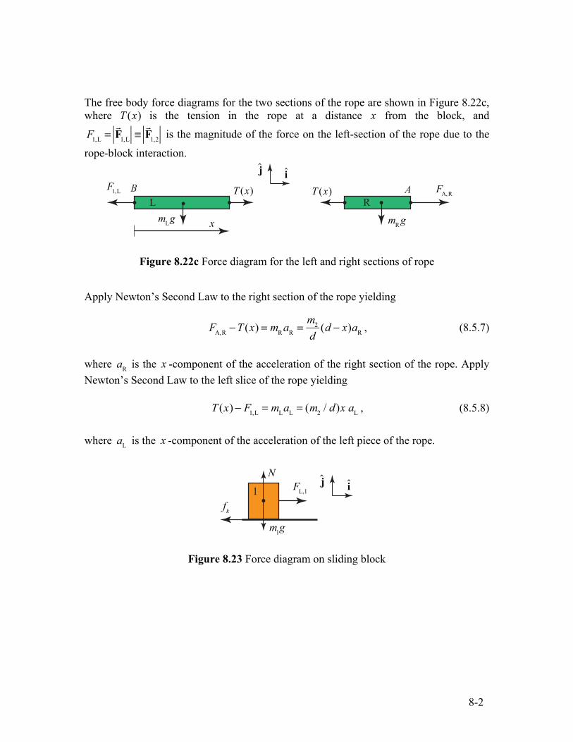
The free body force diagrams for the two sections of the rope are shown in Figure 8.22c, where T (x) is the tension in the rope at a distance x from the block, and
F1,L = ! F1,L ≡
! F1,2 is the magnitude of the force on the left-section of the rope due to the
rope-block interaction.
L R. . . AB . x
T (x) ij
FA, T (x)F1,L .. mR gmL
g
R
Figure 8.22c Force diagram for the left and right sections of rope
Apply Newton’s Second Law to the right section of the rope yielding
8-2
FA,R − T (x) = mR aR = md
2 (d − x)aR , (8.5.7)
where aR is the x -component of the acceleration of the right section of the rope. Apply Newton’s Second Law to the left slice of the rope yielding
= (m2 / d)x aL , (8.5.8)T (x) − F1,L = mLaL
where aL is the x -component of the acceleration of the left piece of the rope.
N j iFL,1 1.
fk m1g
Figure 8.23 Force diagram on sliding block
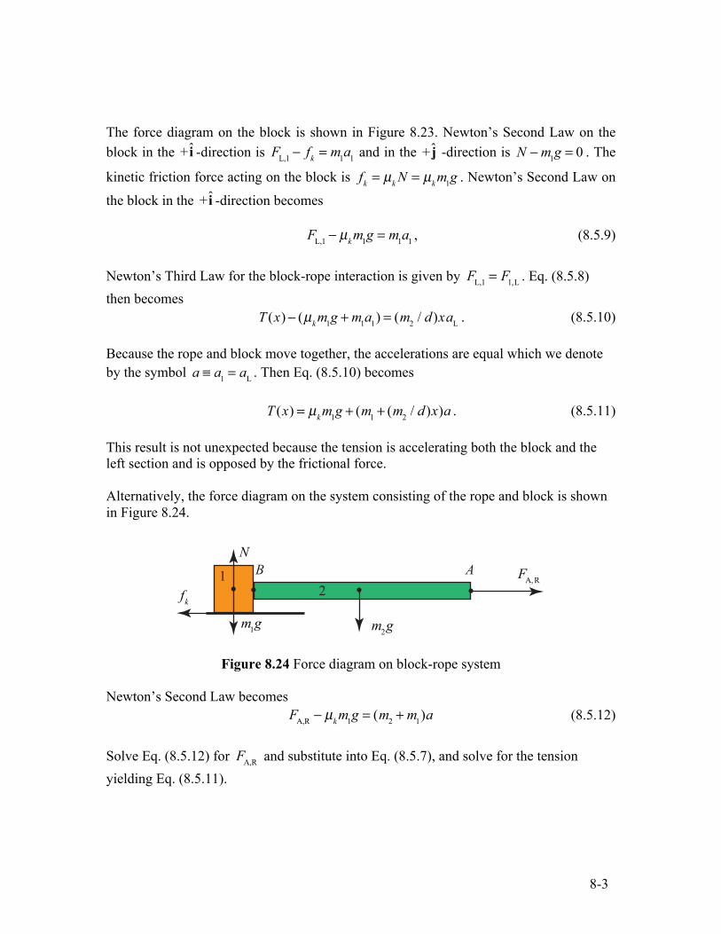
The force diagram on the block is shown in Figure 8.23. Newton’s Second Law on the block in the + i -direction is FL,1 − fk = m1a1 and in the + j -direction is N − m1g = 0 . The
kinetic friction force acting on the block is fk = µk N = µkm1g . Newton’s Second Law on
the block in the + i -direction becomes
− µkm1g = m1a1 , (8.5.9)FL,1
Newton’s Third Law for the block-rope interaction is given by FL,1 = F1,L . Eq. (8.5.8) then becomes
T (x) − (µkm1g + m1a1) = (m2 / d)xaL . (8.5.10)
Because the rope and block move together, the accelerations are equal which we denote by the symbol a ≡ a1 = aL . Then Eq. (8.5.10) becomes
T (x) = µkm1g + (m1 + (m2 / d)x)a . (8.5.11)
This result is not unexpected because the tension is accelerating both the block and the left section and is opposed by the frictional force.
Alternatively, the force diagram on the system consisting of the rope and block is shown in Figure 8.24.
8-3
. AB
2 1
m1g
N
fk . ..
m2 g
FA, R
Figure 8.24 Force diagram on block-rope system
Newton’s Second Law becomes FA,R − µk m1g = (m2 + m1)a (8.5.12)
Solve Eq. (8.5.12) for FA,R and substitute into Eq. (8.5.7), and solve for the tension yielding Eq. (8.5.11).
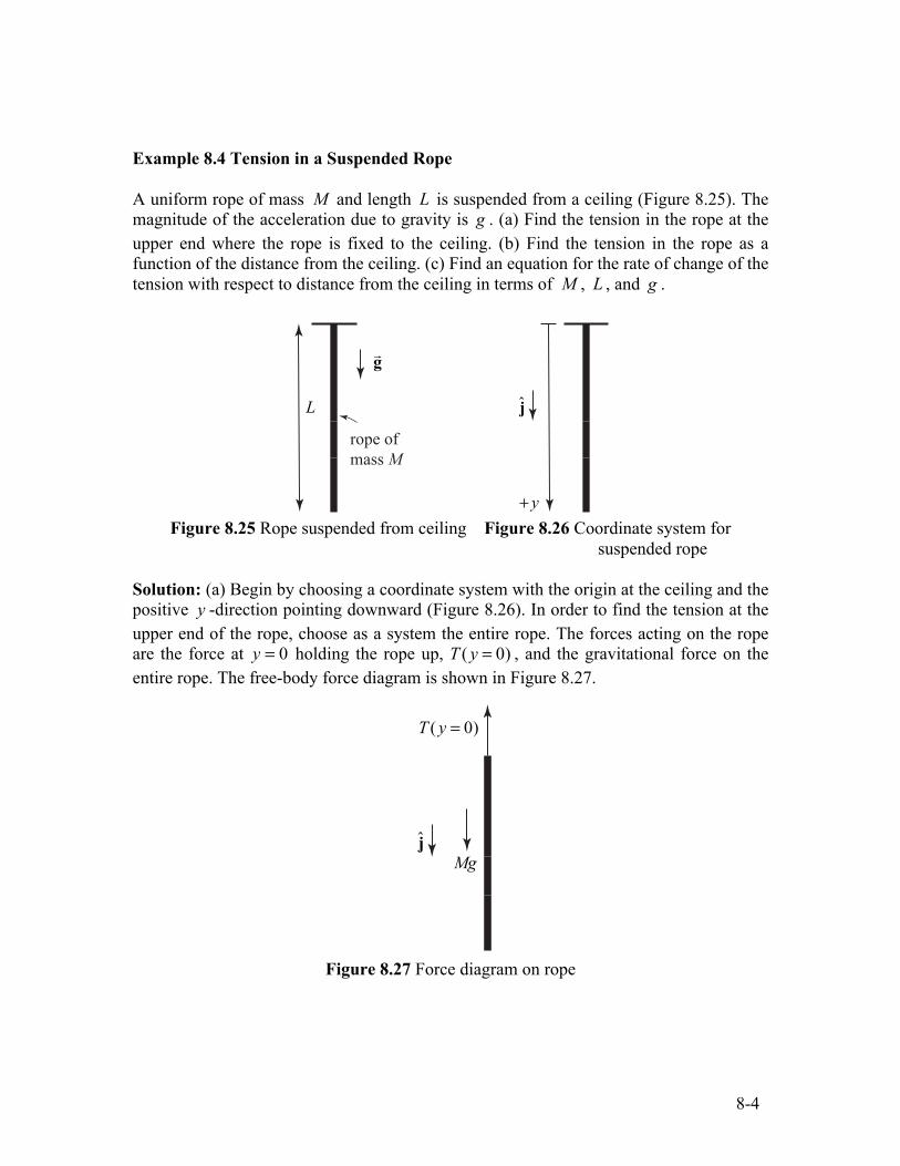
Example 8.4 Tension in a Suspended Rope
A uniform rope of mass M and length L is suspended from a ceiling (Figure 8.25). The magnitude of the acceleration due to gravity is g . (a) Find the tension in the rope at the upper end where the rope is fixed to the ceiling. (b) Find the tension in the rope as a function of the distance from the ceiling. (c) Find an equation for the rate of change of the tension with respect to distance from the ceiling in terms of M , L , and g .
g
L
rope of mass M
j
+ y Figure 8.25 Rope suspended from ceiling Figure 8.26 Coordinate system for
suspended rope
Solution: (a) Begin by choosing a coordinate system with the origin at the ceiling and the positive y -direction pointing downward (Figure 8.26). In order to find the tension at the upper end of the rope, choose as a system the entire rope. The forces acting on the rope are the force at y = 0 holding the rope up, T ( y = 0) , and the gravitational force on the entire rope. The free-body force diagram is shown in Figure 8.27.
8-4
T ( y = 0)
j Mg
Figure 8.27 Force diagram on rope

Because the acceleration is zero, Newton’s Second Law on the rope is Mg − T ( y = 0) = 0 . Therefore the tension at the upper end is T ( y = 0) = Mg .
(b) Recall that the tension at a point is the magnitude of the action-reaction pair of forces acting at that point. Make an imaginary slice in the rope a distance y from the ceiling separating the rope into an upper segment 1, and lower segment 2 (Figure 8.28a). Choose the upper segment as a system with mass m1 = ( M / L) y . The forces acting on the upper segment are the gravitational force, the force T ( y = 0) holding the rope up, and the tension T ( y) at the point y , that is pulling the upper segment down. The free-body force diagram is shown in Figure 8.28b.
T ( y = 0) (a) (b)
y y 1 j1
m1gj T ( y)
L y 2
Figure 8.28 (a) Imaginary slice separates rope into two pieces. (b) Free-body force diagram on upper piece of rope
Apply Newton’s Second Law to the upper segment: m1g + T ( y) − T ( y = 0) = 0 . Therefore the tension at a distance y from the ceiling is T ( y) = T ( y = 0) − m1g . Because m1 = ( M / L) y is the mass of the segment piece and Mg is the tension at the upper end, Newton’s Second Law becomes
8-5
T ( y) = Mg(1− y / L) (8.5.13)
As a check, we note that when y = L , the tension T ( y = L) = 0 , which is what we expect because there is no force acting at the lower end of the rope.
(c) Differentiate Eq. (8.5.13) with respect to y yielding
dT = −( M / L)g . (8.5.14)dy
The rate that the tension is changing at a constant rate with respect to distance from the top of the rope.
8.5.2 Continuous Systems and Newton’s Second Law as a Differential Equations
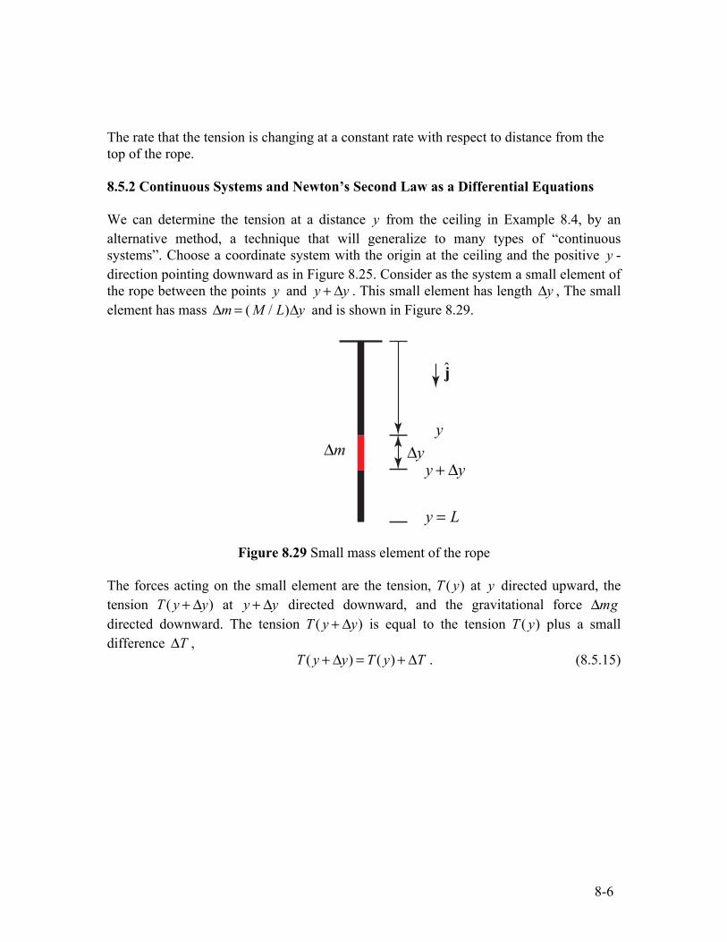
We can determine the tension at a distance y from the ceiling in Example 8.4, by an alternative method, a technique that will generalize to many types of “continuous systems”. Choose a coordinate system with the origin at the ceiling and the positive y -direction pointing downward as in Figure 8.25. Consider as the system a small element of the rope between the points y and y + Δy . This small element has length Δy , The small element has mass Δm = ( M / L)Δy and is shown in Figure 8.29.
j
y y y + y
y = L
m
Figure 8.29 Small mass element of the rope
The forces acting on the small element are the tension, T ( y) at y directed upward, the tension T ( y + Δy) at y + Δy directed downward, and the gravitational force Δmg directed downward. The tension T ( y + Δy) is equal to the tension T ( y) plus a small difference ΔT ,
T ( y + Δy) = T ( y) + ΔT . (8.5.15)
8-6
MIT OpenCourseWarehttps://ocw.mit.edu
8.01 Classical MechanicsFall 2016
For Information about citing these materials or our Terms of Use, visit: https://ocw.mit.edu/terms.