ex3_ltbeam
DESCRIPTION
LTB analysisTRANSCRIPT

Lateral-torsional buckling:
bending about its major axis, failure mayoccur by a form of buckling whichinvolves lateral deflection and twisting.

y
zE I y⋅
E I z⋅
E: modulus of elasticity
Iz: moment of inertia about minor axis
G: shear modulus of elasticity
It: torsion constant
E: modulus of elasticity
Iz: moment of inertia about minor axis
G: shear modulus of elasticity
It: torsion constant
M crπL
E I z⋅ G⋅ I t⋅⋅

• Perfectly elastic, initially straight, loaded byequal and opposite end moments about itsmajor axis.
• Unrestrained along its length
• End Supports …
– Twisting and lateral deflection prevented.
– Free to rotate both in the plane of the weband on plan.
Iw: Warping constantIw: Warping constant
Conditions to determine McrConditions to determine Mcr
M crπL
E I z⋅ G⋅ I t⋅⋅
M crπL
E I z⋅ G I t⋅ E I w⋅L2
π2
⋅+
⋅⋅

Critical Buckling Moment for uniformbending moment diagram is:
+=
z2
t2
z
w2
z2
cr EIGIL
II
LEIM
ππ
Includes:
• Lateral flexural stiffness EIEIzz
• Torsional and Warping stiffnesses GItand EIEIww
Their relative importance depends on thetype of cross-section used.

• The elastic critical moment for a beamunder uniform bending moment is:
t
wtzcr GIL
EIGIEIL
M 2
2
1 ππ+=
• The elastic critical moment (mid-spanmoment) for a beam with a centralpoint load is
t
wtzcr GIL
EIGIEIL
M 2
2
124.4 π+=
which is increased from the basic(uniform moment) case by a factorC1=4.24/π=1.365

EC3 expresses the elastic critical momentMcr for a particular loading case as:
t
wtzcr GIL
EIGIEIL
CM 2
2
1 1ππ
+=
C1 appears as
1/ C10.5 in expressions for λLT.
L Mmax C1
M
M
M
FL/4
FL/8
FL/4
1,00
1,879
2,752
1,365
1,132
1,046
Loads Bendingmoment
M M
M
M -M
F
F
FF= = = =

• Can include the effect of differentsupport conditions by redefining theunrestrained length as an effectiveeffectivelengthlength– Lateral bending restraint: k– Warping restraint: kw
• Basic case assumes end conditionswhich preventprevent lateral movementlateral movement andtwisttwist but permit rotation on plan.permit rotation on plan.
End support conditionsEnd support conditions

•kw = 1.0 unless special provision forwarping fixing is made.
•EC3 recommends k values of
–0.5 for fully fixed ends,
–0.7 for one free and one fixed end
–1.0 for two free ends.
0.50.5
1.01.0
1.01.0
0.50.5

• Loads applied to top flangetop flange aredestabilizing
•destabilizing increases with depth ofincreases with depth ofsectionsection and/or as span reducesas span reduces


Beams with intermediate lateral supports
the segmentssegments of the beam betweenrestraints may be treated in isolationtreated in isolation
Lengths of beams between restraintsshould use an effective length factork of 1,01,0 not 0,70,7
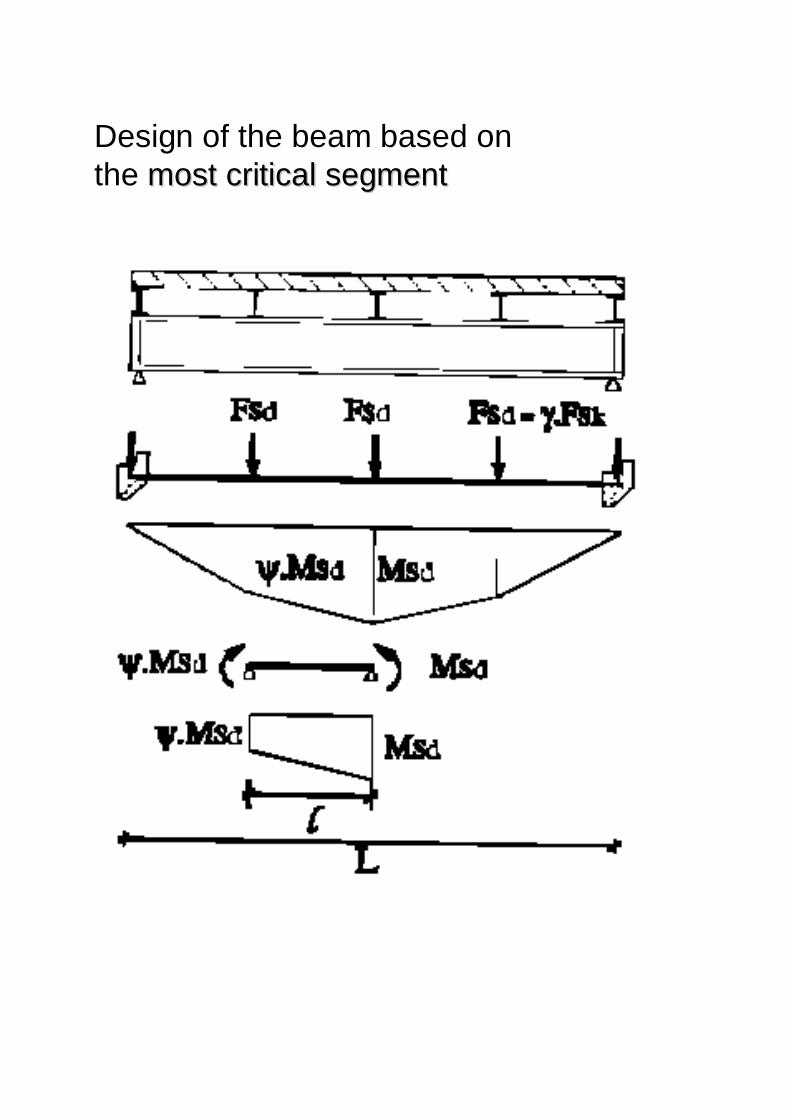
Design of the beam based onthe most critical segmentmost critical segment

beam continuous over a number of spans
--Treat as individual spansindividual spans--taking into account the shapeshape of thebending momentbending moment diagram within each spaneach span--as a result of continuity using the CC11factorfactor
C1 = 1,88 – 1,40ψ + 0,52ψ2C1 = 1,88 – 1,40ψ + 0,52ψ2
Ψ=−1,C1=2,927
Ψ=0,C1=1,88

Non-dimensional plot permits resultsfrom different test series to becompared
Intermediate slenderness: adverselyaffected by inelasticity and geometricalimperfections
0
Stocky Slender
pl
cr
1,0
1,0 MM
λ =LT
Intermediate
pl
crMM
pl
MM
stocky beams λLT ≤ 0.4. Lateral torsionalbuckling is not considered
slender beam λLT ≥ 1.2. Resistance closeto Mcr.
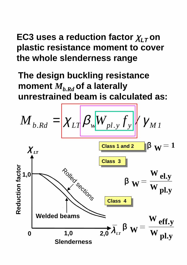
EC3 uses a reduction factor χLT onplastic resistance moment to coverthe whole slenderness range
The design buckling resistancemoment Mb.Rd of a laterallyunrestrained beam is calculated as:
1Myy.plwLTRd.b /fWM γβχ=
0
Welded beams
Rolled sections
SlendernessλLT
χ LTχ LT
Red
uctio
n fa
ctor
1,0 2,0
1,0
β W 1Class 1 and 2Class 1 and 2
Class 3Class 3
β WW el.yW pl.y
Class 4Class 4
β WW eff.yW pl.y

The non-dimensional slenderness is calculated:
• EITHER by
cryyplw
crRdplLT
MfW
MM
/
/
.
.
⋅⋅=
=
β
λ
• OR using
5.0w
1
LTLT β
λλλ
=
5.0
1 fyE
= πλ
[ ] 5,022
1
LTLTLT
LTλφφ
χ−+
=
+−∝+= 2)2.0(15,0 LTLTLTLT λλφ
αLT = 0,21 for rolled sections
αLT = 0,49 for welded sections

w
y
cr
Ypl
wy
cr
Ypl
cryyplw
crRdplLT
fE
MWE
Ef
MWE
MfW
MM
βπ
π
βπ
π
β
λ
⋅⋅
⋅⋅
=
⋅⋅
⋅⋅⋅
=
⋅⋅=
=
2
.2
2.
2
.
.
/
/
5.0w
1
LTLT β
λλλ
=
ε
πλ
⋅=
=
93.9
5.0
1 fyE


A main girder is simply supported. At midspan a side girder is connected by anominally pinned connection. Lateralrestraints are assumed at the supports. Thestructural details and the loading are givenin the following figures.
Main girder: IPE 500
Steel grade S275
Span: L = 7 m
Dead load: g = 3.0 kN/m
Imposed load: q = 5.0 kN/m; P = 140 kN

Load combination:
1.35g + 1.5 ( q + P) or 1.35 (g + q +P)
MSd1 = (1.35g)L2/8 + (1.5q)L2/8 + (1.5P)L/4
= 1.35x3.0x72/8 + 1.5x5.0x72/8 + 1.5x140x7/4
= 438.2 kNm
MSd2 = (1.35g)L2/8 + (1.35q)L2/8 + (1.35P)L/4
= 1.35x3.0x72/8 + 1.35x5.0x72/8 + 1.35x140x7/4
= 396.9 kNm
MSd = max (MSd1, MSd2) = 438.2 kNm
Internal moment and forces

VSd1 = (1.35g)L/2 + (1.5q)L/2 + (1.5P)/2
= 1.35x3.0x7/2 + 1.5x5.0x7/2 + 1.5x140/2
= 145.4 kN
VSd2 = (1.35g)L/2 + (1.35q)L/2 + (1.35P)/2
= 1.35x3.0x7/2 + 1.35x5.0x7/2 + 1.35x140/2
= 132.3 kN
VSd = max (VSd1, VSd2) = 145.4 kN
Resistance at ULS
S275à fy = 275 N/mm2 ε = √235/275=0.92
Flange: c/t = 100/16 = 6.3 < 10ε = 9.2 Class 1
Web: d/t = 426/10.2 = 41.8 < 72 ε = 66.24 Class 1
Classification of the cross-section

Shear resistance verification:
VRd = Av( fy/√3)/γM0
= (5.10x102x275/ √3/1.1)x10-3
= 736.1 kN > 145.4 kN OK!
At mid span:
0.5VRd = 0.5x736.1 = 368.1 kN > 105 kN
-- no interaction bending-shear is required
d/t = 41.8 < 69 ε = 63.5
-- no shear buckling verification is required
Moment resistance verification:
Moment resistance for Class 1 or 2 cross-section
Mc.Rd = Wpl fy / γM0
Wpl = 2194 x 103 mm3
Mc.Rd = 2194 x 103 x 275 / 1.1 = 548.5 kNm

Critical bending moment for doubly symmetricand transverse load applied on shear center
kw = 1.0, k = 1.0, L = 3.5 m,
C1 either from Table F.1.1 C1 = 1.88
kNm1905.8102140
107.89105.3039.0101249000105.3
10214021000088.1
4
4626
122
42
=⋅
⋅⋅⋅⋅+⋅
⋅⋅
⋅⋅⋅=
πcrM
or from C1 = 1.88-1.40Ψ + 0.52 Ψ2
Ψ = 0à C1 = 1.88

Lateral torsional buckling verification
0.40.56
/
/
.
.
>=
⋅⋅=
=
cryyplw
crRdplLT
MfW
MM
β
λ
Lateral torsional buckling verification is required
1Myy.plwLTRd.b /fWM γβχ=
β W 1Class 1 and 2Class 1 and 2 β W 1Class 1 and 2Class 1 and 2

αLT = 0,21 for rolled sections
6946.0]0.560.2)-0.21(0.560.5[1
)2.0(15.0
2
2
=++=
+−∝+= LTLTLTLT λλφ
[ ]9045.0
15,022
=−+
=LTLTLT
LTλφφ
χ
kNm496.11.1/2751021940.9045
/3
1..
=⋅⋅⋅=
= MyyplwLTRdb fWM γβχ
MRd = min (Mc.Rd, Mb.Rd) = min (548.5, 496.1)
= 496.1 kNm > 438.2 kNm OK!

Serviceability verification
Load combination for serviceability
g + (q+P)
Deflection due to dead load
δ1 = (5/384) (gL4)/(EIy)
= (5/384)(3 x 74x1012)(210000x48200x104)
= 0.93 mm
Deflection due to imposed load
δ2 = (5/384) (qL4)/(EIy)+(1/48)(PL3)/(EIy)
= (5/384)(5 x 74x1012)(210000x48200x104)
+(1/48)(140x73x1012) (210000x48200x104)
= 11.4 mm = l / 614 < l / 300Maximum deflection
δmax = 11.4 + 0.93 = 12.33 mm
= l / 570 < l / 250 OK!