ex-fluorescent light fittings 2 3 4 5 6 7 8 9 · ex-emergency light fitting ellk 92... ... lighting...
TRANSCRIPT

2.68EX-PHOTOCELL
2.70LIGHTING MOUNTING SYSTEMS
2.56EX-LIGHT FITTING nLLK 08. . . FOR ZONE 2
2.46EX-d LIGHT FITTING AB 12 AND EVF. . .
2.38EX-RECESSED CEILING LIGHT FITTING RLF 250. . .
2.26EX-RECESSED CEILING LIGHT FITTING eLLB 20. . .
2.18EX-EMERGENCY LIGHT FITTING eLLK 92. . . NIB
2.14EX-POLE MOUNTED LIGHT FITTING eLLM 92. . .
2.12EX-LIGHT FITTING eLLK 92. . .
2.20EX-LIGHT FITTING eLLK 92. . . – MAIN FEATURES
E X - F L U O R E S C E N T L I G H T F I T T I N G S
2.62EX-EMERGENCY LIGHT FITTING nLLK 08. . . N FOR ZONE 2
1
2
3
4
5
6
7
8
9
10
11
12

2.2 C O O P E R C R O U S E - H I N D S G M B H
I F ie ld of appl icat ions and main features I
The best choice for an economical
solution for the illumination of probable
explosive environments is the fluores -
cent lamp.
The advantages of fluorescent lamps
in light fittings:
• worldwide availability
• low cost
• very good colour reproduction
• immediate starting
• easy handling
• long service life with EVG-Technology
• immediate restart
• standardised disposal
of the fluorescent lamps
nLLK 08...
eLLB 20... RLF 250...
AB 12...
EVF...eLLK 92...
Depending on the proposed usage
there is a variety of groups to choose
from:
• eLLK/M 92...:
Surface and pole mounted for
use in the Zones 1, 2, 21 and 22
• nLLK 08...:
Surface mounted for use in
the Zones 2, 21 and 22
• eLLB 20 and RLF 250…...:
Recessed ceiling mounting
for use in the Zones 1, 2, 21 and 22
• AB 12.../EVF..:
Flameproof surface mounted for use
in the zones 12, 2 and 22
I F ie ld of appl icat ions and main features I
C O O P E R C R O U S E - H I N D S G M B H 2.3
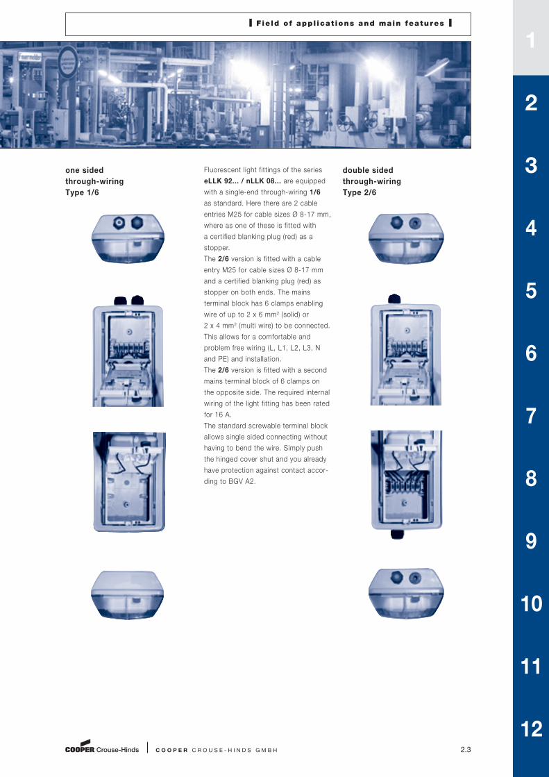
Fluorescent light fittings of the series
eLLK 92... / nLLK 08... are equipped
with a single-end through-wiring 1/6
as standard. Here there are 2 cable
entries M25 for cable sizes Ø 8-17 mm,
where as one of these is fitted with
a certified blanking plug (red) as a
stopper.
The 2/6 version is fitted with a cable
entry M25 for cable sizes Ø 8-17 mm
and a certified blanking plug (red) as
stopper on both ends. The mains
terminal block has 6 clamps enabling
wire of up to 2 x 6 mm2 (solid) or
2 x 4 mm2 (multi wire) to be connected.
This allows for a comfortable and
problem free wiring (L, L1, L2, L3, N
and PE) and installation.
The 2/6 version is fitted with a second
mains terminal block of 6 clamps on
the opposite side. The required internal
wiring of the light fitting has been rated
for 16 A.
The standard screwable terminal block
allows single sided connecting without
having to bend the wire. Simply push
the hinged cover shut and you already
have protection against contact accor-
ding to BGV A2.
double sided
through-wiring
Type 2/6
one sided
through-wiring
Type 1/6
1
2
3
4
5
6
7
8
9
10
11
12

2.4
E X - L I G H T F I T T I N G S
The fluorescent lamp series eLLK 92...,
eLLM 92..., nLLK 08... and in some parts
the eLLB 20... have in their architecture,
the same characteristics, which we show
here on hand of the eLLK 92-Series.
Materials
The eLLK 92 light fitting is made of highgrade
plastics that, in addition to the excellent mecha-
nical properties, also feature a high stability
against many chemicals found in industrial
plants. All the materials used for the light fitting
provide are effectively protected against
corrosion and have already been successfully
tried and tested in chemical and off-shore
installations.
Sealing system
The bowl and the enclosure form a labyrinth,
that protects the seal against jet water. The
continuous seal is extremely elastic and, in
conjunction with the locking mechanism,
ensures that the light fitting is sealed tightly for
a long time. As was also confirmed by an ERA
test, this is the only way to reliably maintain the
degree of protection IP66 for a longer period.
Aptitude tests
The eLLK 92 light fitting has already passed
both tests with lateral thrusts due to wind up
to 12 Bft and the ERA1) test specified for British
off-shore installations. Here, for example, the
sealing qualities and the resistance to vibration
are tested.
1) ERA-Test= UK-test institute
for offshore technology
Technical Specia l Featureson hand of the eLLK 92
Combination of high resistant materials
OptimizedSealing system
Standard – two moulded plastic or brass (optional)cable entries for one-endedthrough-wiring
Double thread (MS) for reliable PE contacting of metal gland (optional)
Standard terminal block with 6 terminals for conductors up to 2 x 6 mm2
Optional double-ended through-wiring for cable connection
Enclosure made of polyester reinforced with glass fibre
Special Ex-EVG in the type of protection Ex d to meet high requirements
Locking bolt for operating the light fitting locking mechanism on both sides
Bowl made of transparent, impact-resistant polycarbonate
Sockets for the hinges of protective bowl – on both sides
Internal sealing system for IP66
Special lamp socket in the type of protection Ex e for bi-pin lamps to IEC 81
Moulded plastic or brass cable entries for double-ended cable connection (optional)

C O O P E R C R O U S E - H I N D S G M B H 2.5
light fittings that were installed at a
later point in time. The fact that the
locking mechanism can be operated
on both sides and that the protective
bowl is hinged on both sides, means
that there is plenty of scope for the
arrangement of light fittings. The bowl
can simply be swung open in the re-
spective direction without tools – this
is made possible by the hinge fasteners
fitted on both sides of the light fitting
housing. A quarter turn of the locking
bolt and the bowl opens up down-
wards. The hinges on the cover are
fixed in such a way that the replace-
ment lamps can be safely deposited in
the bowl, thus saving time when repla-
cing lamps. The bowl cannot fall down,
even in wind and rain.
CEAG
Standard version for two cables
The standard version of the eLLK 92
is designed for a single-ended through-
wiring. According to the verdict in
an independent expertise, together
with the easily accessible terminal
compartment, this connection method
results in a time saving of up to 30%
compared to conventional light fittings
using the classical through-wiring
method.
Installation
of the eLLK 92/nLLK 08
Whether it is mounted on rails or
suspended from the sealing, the lion’s
share of the overall costs is taken up
by the installation and electrical con-
nection of the light fitting. Here, due
to the standardized fixing clearances
and the generously dimensioned
terminal compartments, the eLLK 92
provides a high saving potential. The
terminal compartment can be opened
without removing covers or reflectors,
thus permitting the easy connection of
cables.
Three ways – one solution
Depending on the type of installation,
different cable entries could be required
for the connection of the light fitting.
Available for all types are the following:
• M25 x 1.5 Plastic cable entries
• M20 x 1.5 Earthed metal thread
for metal cable entries
• non-metric threads, for example
Myer Hubs 3/4” NPT-Thread
Lamp replacement made easy
Irrespective of how the light fitting is
installed, the locking mechanism can
be operated on either side – this means
that there are no future surprises with
generously dimensioned terminal compartments
Easy lamp replacement
Cost reduction with single-end through-wiring
Plastic cable entries
Metal thread
Myer Hubs (for Conduit-System)
1
2
3
4
5
6
7
8
9
10
11
12

2.6 C O O P E R C R O U S E - H I N D S G M B H
compulsory N/C contact safeguarded against contact
Closing system using the ”strongbox principle“ guarantees a correct sealing
Catch points protective bowl
opening of bowl
closing of bowl
International Ø 26 mm bi-pin fluorescent lamp and the old Ø 38 mm single-pin fluorescent lamp
CEAG products are constanly being advanced and tested in the company’sown lighting laboratory
Locking mechanism
The housing and the protective bowl
are securely locked by means of a
locking mechanism according to the
„strongbox principle“ on both sides that
features as many as 24 latch points .
This new type of locking system featu-
res stainless steel springs that regulate
the pressure applied to the seal, thus
guaranteeing the tightness of the light
fittings, even in the event of changes
due to the ageing of the sealing material
and variable climatic influences.
Double the safety is better
The regulations require the automatic
disconnection of the supply voltage
when the light fitting is opened.
The built-in compulsory NC contact
is safeguarded against inadvertent
operation and, as soon as the locking
mechanism of the light fitting is opera-
ted, it de-energizes all parts that
can be touched. A second interlock
switch increases the safety level for
the operator. Therefore, even if the
lock of the light fitting is actuated
while the protective bowl is still open,
the switch cannot be operated, as, in
this case, the circuit for the light fitting
remains disconnected.
Lamps
All the light fittings in the eLLK 92/
nLLK 08 /eLLB 20 and RLF 250.. series
have been developed and certified for
Ø 26 mm bi-pin fluorescent lamps with
a G 13 lamp cap in accordance with:
IEC 60081 – page 22/20 (18 W)
IEC 60081 – page 24/20 (36 W)
IEC 60081 – page 21/22 (58 W)
This means that the lamps, that are
available all over the world, can be
used for both hazardous and non-
hazardous areas. Not only does this
simplify stock-keeping, but the operator
also benefits from all the technical
advantages in conjunction with EVG
operation. Compared to the old
Ø 38 mm single-pin fluorescent lamps,
the luminous power of the system is
increased by a factor of 2.2. Special
thermo-lamps with 38 mm diameter
can be used in all bi-pin
lamp holder of CEAG fluore-
scent light fittings. This
allows an economical use
of fluorescent lamps even
below ambient temperatures
of –5°C
Lighting engineering
Due to the various fields of
application light fittings are
equipped with a large variety
of lamps and reflectors.
The criteria for the selection
of the types of lamps and
reflectors are basically
determined by the type of
lighting required (illumination
of surfaces or objects, etc.)
and the economic efficiency.
When planning a lighting installation,
the polar curves of the luminous
intensity of the light fittings being
used are required in order to calculate
the illumination distribution.
C O O P E R C R O U S E - H I N D S G M B H 2.7
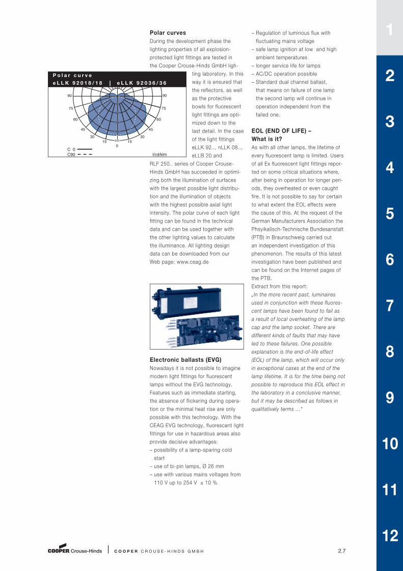
Polar curves
During the development phase the
lighting properties of all explosion-
protected light fittings are tested in
the Cooper Crouse-Hinds GmbH ligh-
ting laboratory. In this
way it is ensured that
the reflectors, as well
as the protective
bowls for fluorescent
light fittings are opti-
mized down to the
last detail. In the case
of the light fittings
eLLK 92.., nLLK 08..,
eLLB 20 and
RLF 250.. series of Cooper Crouse-
Hinds GmbH has succeeded in optimi-
zing both the illumination of surfaces
with the largest possible light distribu-
tion and the illumination of objects
with the highest possible axial light
intensity. The polar curve of each light
fitting can be found in the technical
data and can be used together with
the other lighting values to calculate
the illuminance. All lighting design
data can be downloaded from our
Web page: www.ceag.de
– Regulation of luminous flux with
fluctuating mains voltage
– safe lamp ignition at low and high
ambient temperatures
– longer service life for lamps
– AC/DC operation possible
– Standard dual channel ballast,
that means on failure of one lamp
the second lamp will continue in
operation independent from the
failed one.
EOL (END OF LIFE) –
What is it?
As with all other lamps, the lifetime of
every fluorescent lamp is limited. Users
of all Ex fluorescent light fittings repor-
ted on some critical situations where,
after being in operation for longer peri-
ods, they overheated or even caught
fire. It is not possible to say for certain
to what extent the EOL effects were
the cause of this. At the request of the
German Manufacturers Association the
Phsyikalisch-Technische Bundesanstalt
(PTB) in Braunschweig carried out
an independent investigation of this
phenomenon. The results of this latest
investigation have been published and
can be found on the Internet pages of
the PTB.
Extract from this report:
„In the more recent past, luminaires
used in conjunction with these fluores -
cent lamps have been found to fail as
a result of local overheating of the lamp
cap and the lamp socket. There are
different kinds of faults that may have
led to these failures. One possible
explanation is the end-of-life effect
(EOL) of the lamp, which will occur only
in exceptional cases at the end of the
lamp lifetime. It is for the time being not
possible to reproduce this EOL effect in
the laboratory in a conclusive manner,
but it may be described as follows in
qualitatively terms ...“
Electronic ballasts (EVG)
Nowadays it is not possible to imagine
modern light fittings for fluorescent
lamps without the EVG technology.
Features such as immediate starting,
the absence of flickering during opera-
tion or the minimal heat rise are only
possible with this technology. With the
CEAG EVG technology, fluorescent light
fittings for use in hazardous areas also
provide decisive advantages:
– possibility of a lamp-sparing cold
start
– use of bi-pin lamps, Ø 26 mm
– use with various mains voltages from
110 V up to 254 V ± 10 %
C 0 C90
l/cd/klm
90
75
60
45
30 15
0 15
30
45
60
75
90
40
80
120
160
200
P o l a r c u r v e
e L L K 9 2 0 1 8 / 1 8 ⎮ e L L K 9 2 0 3 6 / 3 6
1
2
3
4
5
6
7
8
9
10
11
12

2.8 C O O P E R C R O U S E - H I N D S G M B H
The solution for Zone 1
applications – CEAG EVG 09
All the EVGs (electronic ballast’s)
supplied by CEAG since 1988 feature
monitoring of the lamp circuit, detection
of the rectifier effect, as well as a
shutdown of the circuit in the event
that the lamp does not strike. There -
fore, the CEAG EVGs already ensured
a high level of safety at the service
life of the lamps long before the discus-
sions on EOL ever started. The new
CEAG EVG 09 also fulfils the relevant
EOL requirements of the industrial stan-
dard IEC 61347-2-3 (§ 17.2 and 17.3),
as well as those laid down in the latest
draft of IEC 60079-7 Ed. 4 7/2006
(Electrical Apparatus in the type of pro-
tection Increased Safety), for luminaires
for use in potentially explosive atmos-
pheres Zone 1. Thus, the CEAG EVG 09,
which is certified to: BVS 09 ATEX E 054 U,
meets the latest findings and the
newest standards.
The advantages for you:
• Time-tested and reliable technology
• Latest lamp circuit monitoring as an
additional safety factor
• Meets all requirements of the
standard draft IEC 60079-7 for
luminaires with fluorescent lamps in
“Increased Safety” (EOL)
• EVG designed specially for rough
operating conditions of Zone 1 – not
just an encapsulated industrial EVG
• Thermally optimised circuitry for long
service life, even in high ambient
temperatures
• Wide input voltage range and DC
operation for universal use
• Two separate lamp circuits (autarkic
switching) provide more safety for
your employees and installations
• Practically insensitive to network
harmonics and over-voltage
influences
• Isolation of one lamp circuit for use
in emergency lighting installations
(economic battery use)
Which protective circuits does
the new EVG 09 have?
The standard DIN EN 61347-2-3
(VDE 0712-33), which was issued in
February 2005, only stipulates a per -
manent monitoring of the lamp circuit
for EOL effects for T4 and T5 lamps
(16 mm and thinner). The draft version
of the standard IEC 60079-7, which
was derived from this standard, lays
down the test requirements for Ex-e
light fittings with cold start EVGs for T6
(26 mm) fluorescent lamps.
Unlike industrial luminaires with EVGs,
Ex-e luminaires shall fulfil all of the
relevant conditions of this standard.
The EVG 09 in practice:
Explosion protected luminaires
with trademark CEAG
All these functions are just one compo-
nent in the extensive safety concept of
the CEAG EVG 09. The use of high im-
pact resistant plastic materials for the
encapsulation in the type of protection
Ex-de, as well as the additional unit
fuses for the event that a fault occurs
rounds off the whole package.
The new CEAG EVG 09 will become
standard for our fluorescent light
fittings series:
eLLK 92 .../.. , eLLM 92 .../…. NIB
as well as fort he recessed ceiling
luminaires eLLB 20… and RLF 250…

C O O P E R C R O U S E - H I N D S G M B H 2.9
Robust technology for extreme
applications
The operation of explosion-protected
light fittings places high requirements
on the reliability and durability of the
circuits being used. In addition to tem-
perature, moisture and mechanical
stress, mains contamination or voltage
peaks can affect the light fittings.
Here the EVGs specially developed by
Cooper Crouse-Hinds GmbH provide
safe protection against harmful influen-
ces. Whereas conventional industrial
EVGs are designed for an ambient
temperature of the light fittings of
up to + 30°C, the CEAG EVGs are
designed for an ambient temperature
of + 50°C. The large-scale printed
wiring board layouts ensure an even
heat distribution, through-connections
and encapsulation of sensitive compo-
nents provide mechanical protection.
A hermetically sealed enclosure pro -
vides protection against undesirable
substances that could cause damage
to the PCB.
to ensure a constant good quality.
Cooper Crouse-Hinds GmbH has been
manufacturing EVGs for more than
25 years and has the necessary know-
how. In addition to the routine verifi -
cations and tests carried out on all
apparatus, stress tests are carried out
on individual batches to ensure safe
findings with regard to component
specifications.
Computer-aided final
inspections
The uncompromising safety of the
explosion-protected eLLK 92 light
fittings is maintained throughout the
various production stages and includes
the final inspection. Each light fitting
is tested in detail by a computer test
program. All data relating to the
manufacture and safety is stored and
can still be called up years later. This is
where the Cooper Crouse-Hinds GmbH
quality assurance system, that is certi-
fied to ISO 9001:2000, clearly makes
it mark.
Direct or alternating voltage?
Conventional ballasts only work with
an alternating voltage and can only
be used with group or central battery
installations under certain conditions.
Cooper Crouse-Hinds GmbH, as the
leading manufacturer of emergency
lighting installations, offers an explo-
sion-protected ballast that can be
operated with alternating and direct
voltages.
Quality cannot be left to chance
Extensive testing and a highly automa-
ted production process are necessary
EVG-Capsulation
1
2
3
4
5
6
7
8
9
10
11
12
2.10 C O O P E R C R O U S E - H I N D S G M B H
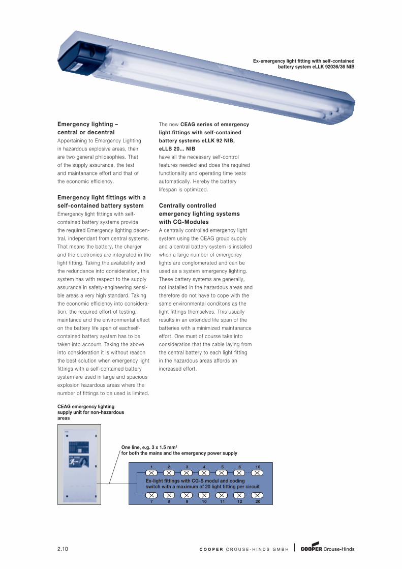
The new CEAG series of emergency
light fittings with self-contained
battery systems eLLK 92 NIB,
eLLB 20... NIB
have all the necessary self-control
features needed and does the required
functionality and operating time tests
automatically. Hereby the battery
lifespan is optimized.
Centrally controlled
emergency lighting systems
with CG-Modules
A centrally controlled emergency light
system using the CEAG group supply
and a central battery system is installed
when a large number of emergency
lights are conglomerated and can be
used as a system emergency lighting.
These battery systems are generally,
not installed in the hazardous areas and
therefore do not have to cope with the
same environmental conditons as the
light fittings themselves. This usually
results in an extended life span of the
batteries with a minimized maintanance
effort. One must of course take into
consideration that the cable laying from
the central battery to each light fitting
in the hazardous areas affords an
increased effort.
Emergency lighting –
central or decentral
Appertaining to Emergency Lighting
in hazardous explosive areas, their
are two general philosophies. That
of the supply assurance, the test
and maintanance effort and that of
the economic efficiency.
Emergency light fittings with a
self-contained battery system
Emergency light fittings with self-
contained battery systems provide
the required Emergency lighting decen-
tral, independant from central systems.
That means the battery, the charger
and the electronics are integrated in the
light fitting. Taking the availability and
the redundance into consideration, this
system has with respect to the supply
assurance in safety-engineering sensi-
ble areas a very high standard. Taking
the economic efficiency into considera-
tion, the required effort of testing,
maintance and the environ mental effect
on the battery life span of eachself-
contained battery system has to be
taken into account. Taking the above
into consideration it is without reason
the best solution when emergency light
fittings with a self-contained battery
system are used in large and spacious
explosion hazardous areas where the
number of fittings to be used is limited.
Ex-emergency light fitting with self-contained battery system eLLK 92036/36 NIB
CEAG emergency lighting supply unit for non-hazardousareas
One line, e.g. 3 x 1.5 mm2
for both the mains and the emergency power supply
Ex-light fittings with CG-S modul and codingswitch with a maximum of 20 light fitting per circuit
1 2 3 4 5 6 10
7 8 9 10 11 12 20

C O O P E R C R O U S E - H I N D S G M B H 2.11
To be able to run on the CEAG
emergency light fittings system we
can provide the following light fitting
series eLLK 92, nLLK 08 and eLLB 20
versions with ”CG-S Modules“. This
controlling module controls amongst
other things the data exchange
between the main emergency light
apparatus and the individual light
fittings per power supply cable and
reports all functional errors.
In conjunction with the CG-S Modules,
it is now possible to connect
individually monitored emergency
light fittings to a CEAG emergency
lighting installation with monitoring
system. Here it is now possible to
integrate explosion-protected light
fittings as system light fittings into the
practical monitoring system of CEAG
group or central battery installations.
This combination offers the following
advantages:
– Automatic performance of the
necessary function test with central
record-keeping
– Enormous cost savings as manual
testing is no longer necessary
– Two-lamp operation with mains
supply, single lamp operation
with emergency power supply,
therefore cost saving for batteries
and apparatus
– High degree of safety of emergency
lighting due to constant display of
availability
– Simplified installation:
– mains and emergency power supply
have a common connection
– a separate data line is not required
– a maximum of 20 light fittings
can be connected to one circuit
– automatic performance of the
necessary function tests with
central record-keeping
1
2
3
4
5
6
7
8
9
10
11
12

Standard dual channel ballast
Double-sided safety lock
Safety locking system due
to an integrated forced isolating switch
Safety standard IP66
Connection to CEAG emergency light
monitoring systems possible
International Approvals
2.12
E X - L I G H T F I T T I N G S
The eLLK 92 Ex-protected light fittings for bi-pin
fluorescent lamps are fitted with an electronic
ballast and conform to the ATEX Directive
94/9/EG. The modern economical ballast
EVG 09 according to the latest standards
(IEC 60079-7: 2006) allows a safe and econo -
mical operation of bi-pin fluorescent lamps
G13 according to IEC 60081. Lamps reaching
its end of life will be monitored and securely
switched off (EOL-effect). The high input voltage
range allows international use. Due to the
standard dual channel architecture (with double
lamp fittings) if one fluorescent lamp fails, the
other fluorescent lamp will independently stay
in operation. The standard single-sided through-
wiring in connection with the variety of possi -
bilities offers a cost efficient installation. Double-
sided lock with 10, 20 or 24 latch points allows
the protective bowl to be hingeable on both
sides meaning the fitting can be mounted
without having to pay attention to which side is
the right side. Automatic switch built as a safety
disconnector according to EN 60947 (IEC 664)
with an automatic switch ensuring the discon-
nection of all exposed components when the
fitting is opened. The optional CG-S module
represents an optimum solution for the individual
monitoring of light fittings connected to CEAG
emergency battery systems.
eLLK 92. . . 18 W - 58 WAl l p last ic design for Zone 1 and 21

I eLLK 92. . . (18-58 W) I
C O O P E R C R O U S E - H I N D S G M B H 2.13
1 x 36 W 2 x 36 W
Technical data
eLLK 92018/18 ⎮ eLLK 92036 / eLLK 92036/36 ⎮ eLLK 92058 / eLLK 92058/58
Marking to 94/9/EC II 2 G Ex de IIC T4 / II 2 G Ex de mb II T4 (CG-S variant)
II 2 D Ex tD A21 IP66 T80 °C
EC-Type Examination Certificate BVS 09 ATEX E 034
IECEx-Certificate of Conformity IECEx BVS 09.0033
Marking to IECEx Ex de mb IIC T4
Ex tD A21 IP66 T 80 °C
Permissible ambient temperature -25 °C to +55 °C (Un ≥ 220 V)
-25 °C to +50 °C (Un < 220 V)1)
Frequency 50 - 60 Hz
Power factor cos ϕ ≥ 0.95
Circuit EVG resp. EVG/CG-S
Connecting terminals L1, L2, L3, L, N, PE; max. 2 x 6 mm2 per terminal
Insulation class I
Lamp cap G13 accd. to IEC 60081
Degree of protection accd. EN 60529 IP66
Cable glands/gland plates/enclosure entry holes Ex-e cable glands M25 x 1.5 (plastic) for cables from Ø 8 - 17 mm,
Option: M20 x 1.5 metal thread
Enclosure material Glass-fibre reinforced polyester
Protective cover/protective bowl Polycarbonate
eLLK 92018/18 eLLK 92036 eLLK 92036/36
Rated voltage 110 - 254 V AC / 110 - 254 V AC / 110 - 254 V AC /
110 - 250 V DC 110 - 250 V DC 110 - 250 V DC
Rated voltage CG-S 220 - 254 V AC / 220 - 254 V AC / 220 - 254 V AC /
195 - 250 V DC 195 - 250 V DC 195 - 250 V DC
Rated current 0.18 A 0.18 A 0.34 A
0.19 A (CG-S variant) 0.35 A (CG-S variant)
Lamp/illuminant 2 x T26 / 18 W (T8) 1 x T26 / 36 W (T8) 2 x T26 / 36 W (T8)
Rated luminous flux2) 2700 lm 3350 lm 6700 lm
Light efficiency in operation 78 % 86 % 78 %
Dimensions (L x W x H) 760 x 188 x 130 mm 1360 x 188 x 130 mm 1360 x 188 x 130 mm
Weight approx. 5.2 kg / approx. 7.2 kg approx. 7.4 kg /
approx. 5.6 kg (CG-S variant) approx. 7.7 kg (CG-S variant)
eLLK 92058 eLLK 92058/58
Rated voltage 220 - 254 V AC / 220 - 254 V AC /
195 - 250 V DC 195 - 250 V DC
Rated voltage CG-S 220 - 254 V AC / 220 - 254 V AC /
195 - 250 V DC 195 - 250 V DC
Rated current 0.27 A 0.53 A / 0.54 A (CG-S variant)
Lamp/illuminant 1 x T26 / 58 W (T8) 2 x T26 / 58 W (T8)
Rated luminous flux2) 5200 lm 10400 lm
Light efficiency in operation 83 % 72 %
Dimensions (L x W x H) 1660 x 188 x 130 mm 1660 x 188 x 130 mm
Weight approx. 8.2 kg approx. 9.1 kg / approx. 9.6 kg (CG-S variant)
1) eLLK 92058/58: max. +40 °C
2) depends on used lamps
1
2
3
4
5
6
7
8
9
10
11
12
2.14 C O O P E R C R O U S E - H I N D S G M B H
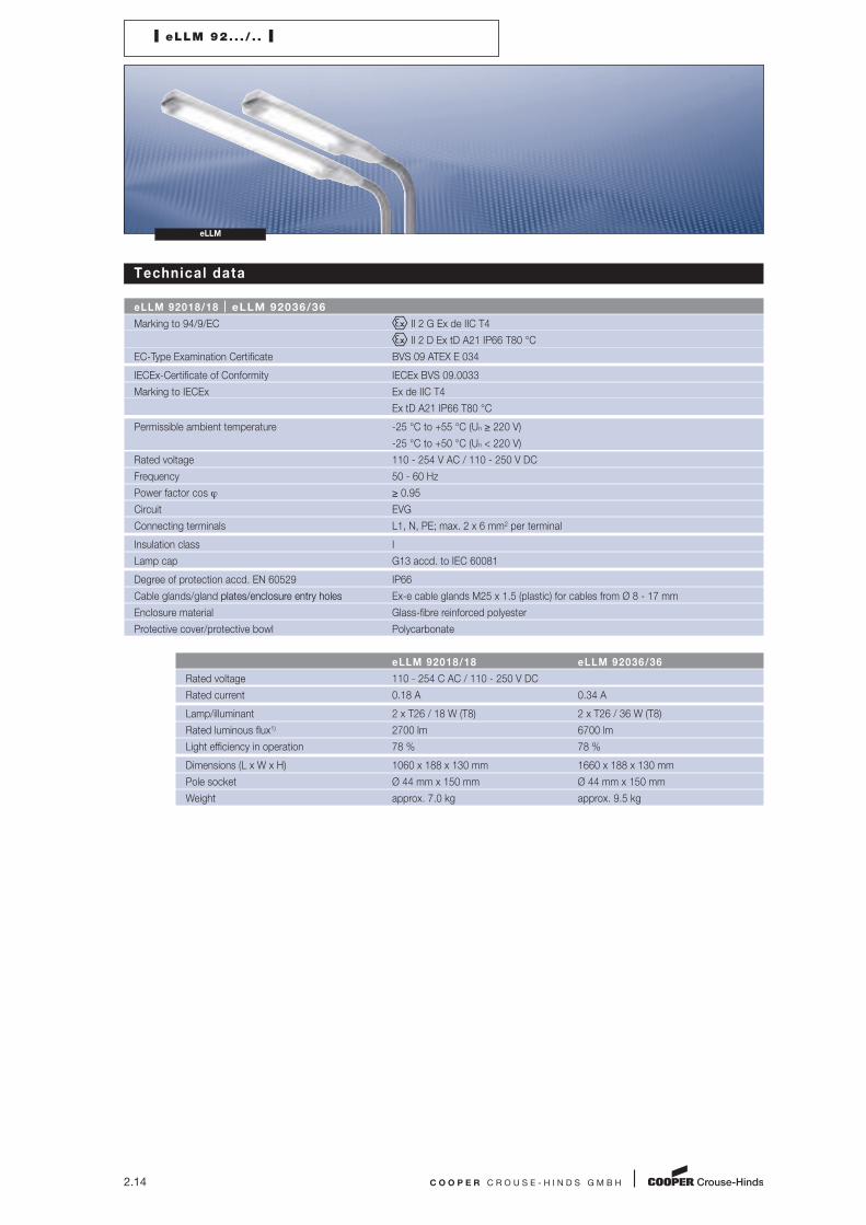
I eLLM 92. . . / . . I
eLLM
Technical data
eLLM 92018/18 ⎮ eLLM 92036/36
Marking to 94/9/EC II 2 G Ex de IIC T4
II 2 D Ex tD A21 IP66 T80 °C
EC-Type Examination Certificate BVS 09 ATEX E 034
IECEx-Certificate of Conformity IECEx BVS 09.0033
Marking to IECEx Ex de IIC T4
Ex tD A21 IP66 T80 °C
Permissible ambient temperature -25 °C to +55 °C (Un ≥ 220 V)
-25 °C to +50 °C (Un < 220 V)
Rated voltage 110 - 254 V AC / 110 - 250 V DC
Frequency 50 - 60 Hz
Power factor cos ϕ ≥ 0.95
Circuit EVG
Connecting terminals L1, N, PE; max. 2 x 6 mm2 per terminal
Insulation class I
Lamp cap G13 accd. to IEC 60081
Degree of protection accd. EN 60529 IP66
Cable glands/gland plates/enclosure entry holes Ex-e cable glands M25 x 1.5 (plastic) for cables from Ø 8 - 17 mm
Enclosure material Glass-fibre reinforced polyester
Protective cover/protective bowl Polycarbonate
eLLM 92018/18 eLLM 92036/36
Rated voltage 110 - 254 C AC / 110 - 250 V DC
Rated current 0.18 A 0.34 A
Lamp/illuminant 2 x T26 / 18 W (T8) 2 x T26 / 36 W (T8)
Rated luminous flux1) 2700 lm 6700 lm
Light efficiency in operation 78 % 78 %
Dimensions (L x W x H) 1060 x 188 x 130 mm 1660 x 188 x 130 mm
Pole socket Ø 44 mm x 150 mm Ø 44 mm x 150 mm
Weight approx. 7.0 kg approx. 9.5 kg

I eLLK 92. . . (18-58 W) I eLLM 92. . . / . . (18 + 36 W) I
C O O P E R C R O U S E - H I N D S G M B H 2.15
Ordering detai ls
Type Terminals Through-wiring Cable Plugs Order No.
single-ended double-ended glands3)
eLLK 92018/18 (2 x 18 W)
1/6-1 1 x 6 x – 2 x M25 x 1.5 1 x blanking 1 2265 875 101
2/6-2 2 x 6 – x 2 x M25 x 1.5 2 x threaded 1 2265 875 103
1/6-1 M1) 1 x 6 x – 2 x M20 x 1.5 1 x threaded 1 2265 875 109
2/6-2 M1) 2 x 6 – x 4 x M20 x 1.5 2 x threaded 1 2265 875 111
eLLK 92018/18 (2 x 18 W)
Level gauge P2 1 x 6 x – 2 x M25 x 1.5 1 x blanking 1 2265 875 126
eLLK 92018/18 CG-S2) (2 x 18 W)
2/6-2 2 x 6 – x 2 x M25 x 1.5 2 x threaded 1 2265 881 103
2/6-2M1) 2 x 6 – x 4 x M20 x 1.5 2 x threaded 1 2265 881 211
eLLM 92018/18 (2 x 18 W)
1/6-1 1 x 3 – – 1 x M25 x 1.5 1 2268 875 101
eLLK 92036 (1 x 36 W)
1/6-1 1 x 6 x – 2 x M25 x 1.5 1 x blanking 1 2263 875 101
2/6-2 2 x 6 – x 2 x M25 x 1.5 2 x threaded 1 2263 875 103
1/6-1 M 1 x 6 x – 2 x M20 x 1,5 1 x threaded 1 2263 875 111
eLLK 92036 (1 x 36 W)
Level gauge P3 1/6-1 1 x 6 x – 2 x M25 x 1.5 1 x blanking 1 2263 875 125
eLLK 92036/36 (2 x 36 W)
1/6-1 1 x 6 x – 2 x M25 x 1.5 1 x blanking 1 2266 875 101
2/6-2 2 x 6 – x 2 x M25 x 1.5 2 x threaded 1 2266 875 103
1/6-1 M1) 1 x 6 x – 2 x M20 x 1.5 1 x threaded 1 2266 875 109
2/6-2 M1) 2 x 6 – x 4 x M20 x 1.5 2 x threaded 1 2266 875 111
eLLK 92036/36 CG-S2) (2 x 36 W)
2/6-2 2 x 6 – x 2 x M25 x 1.5 2 x threaded 1 2266 881 103
2/6-2M1) 2 x 6 – x 4 x M20 x 1.5 2 x threaded 1 2266 881 211
eLLM 92036/36 (2 x 36 W)
1/6-1 1 x 3 – – 1 x M25 x 1.5 1 2269 875 101
eLLK 92058 (1 x 58 W)
1/6-1 1 x 6 x – 2 x M25 x 1.5 1 x blanking 1 2264 875 101
2/6-2 2 x 6 – x 2 x M25 x 1.5 2 x threaded 1 2264 875 103
2/6-2 M1) 2 x 6 – x 4 x M20 x 1.5 2 x threaded 1 2264 875 111
eLLK 92058/58 (2 x 58 W)
1/6-1 1 x 6 x – 2 x M25 x 1.5 1 x blanking 1 2267 875 101
2/6-2 2 x 6 – x 2 x M25 x 1.5 2 x threaded 1 2267 875 103
2/6-2 M1) 2 x 6 – x 4 x M20 x 1.5 2 x threaded 1 2267 875 111
eLLK 92058/58 CG-S2) (2 x 58 W)
2/6-2 2 x 6 – x 2 x M25 x 1.5 2 x threaded 1 2267 881 103
2/6-2 M1) 2 x 6 – x 4 x M20 x 1.5 2 x threaded 1 2267 881 211
1) M: with metal thread, without cable gland2) CG-S: design single monitored emergency light fitting for use in CEAG emergency light supply unit3) With dustcover if entry/thread is not closed
Scope of delivery without lamp and fixing accessories.
2 x 18 W 2 x 18 W2 x 36 W2 x 36 W1 x 36 W
1
2
3
4
5
6
7
8
9
10
11
12

2.16 C O O P E R C R O U S E - H I N D S G M B H
I eLLK 92. . . (18-58 W) I eLLM 92. . . / . . (18 + 36 W) I
eLLK eLLM
Accessories
Lamp for luminaire eLLK92/eLLM92
Type of lamp Power Luminous flux Order No.
socket/ light colour
diameter
Bi-pin socket G13 18 W 1350 lm white 3 2475 900 001
T26/Ø 26 mm (T8)
G13-60081-IEC-2220-1
Bi-pin socket G13 36 W 3350 lm white 3 2475 900 002
T26/Ø 26 mm (T8)
G13-60081-IEC-2420-1
Bi-pin socket G13 58 W 5200 lm white 3 2475 900 003
T26/Ø 26 mm (T8)
G13-60081-IEC-2520-1
Aura-Ultimate 18 W 1300 lm white 3 2475 900 087
T26/Ø 26 mm (T8) Longlife 36 W 3350 lm white 3 2475 900 088
G13-socket 58 W 5200 lm white on request
Aura Super Ex 18 W 1150 lm white 3 2475 900 084
T-HS 26/Ø 26 mm1) 36 W 3000 lm white 3 2475 900 085
Single pin cap Fa6 58 W 4800 lm white on request
Series eLLK 92... and eLLM 92...
Type Order No.
Hexagon screw SW 13 3 2485 000 005
Series eLLM 92018/18 and eLLM 92036/36
Type Order No.
Single sided through wiring 2/6 with 2 entries M25, incl. terminals and mounting material 2 2218 602 000
Fixing materials eLLK 92
Type/code Corrosion Qty. Order No.
protection per light fitting
Eye bolt A2 galvanized 2 2 2480 002 000
Hexagon screw S4 stainless steel 2 2 2480 054 000
Ceiling mounting bracket D92 stainless steel 2 2 2480 092 000
incl. screws and washer
Fixing materials
Type/code Corrosion for pipes Outer Ø Qty. Order No.
protection DIN D (mm) per light fitting
Pipe clamp
R12 hot galvanized 11/4” 38 - 42 2 2 2480 462 000
R14 CrNi 11/4” 38 - 42 2 2 2480 464 000
R22 hot galvanized 11/2” 47 - 51 2 2 2480 472 000
R24 CrNi 11/2” 47 - 51 2 2 2480 474 000
R32 hot galvanized 2” 56 - 60 2 2 2480 482 000
R34 CrNi 2” 56 - 60 2 2 2480 484 000
Wall bracket W27 hot galvanized 42.4 1 2 2483 027 000
Luminaire wall suspension 30° hot galvanized 2 2 2480 000 122
incl. screws and washer1) For luminaires eLLK 923../.. and eLLM 923../.. with single pin caps Fa6
Metal cable glands M20/M25 see page 8.10.
Complete Mounting Systems see page 2.70 to 2.76.

C O O P E R C R O U S E - H I N D S G M B H 2.17
Dimension drawing ⎮ Polar curve ⎮ Accessories
Dim
en
sio
ns i
n m
m
C 0 C90
l/cd/klm
90
75
60
45
30 15
0 15
30
45
60
75
90
40
80
120
160
200
Polar curve
eLLK 92018/18 / eLLK 92036/36
C 0 C90
l/cd/klm
40
80
120
160
200
90
75
60
45
30 15
0 15
30
45
60
75
90
Polar curve
eLLK 92036 / eLLK 92058
C 0 C90
l/cd/klm
90
75
60
45
30 15
0 15
30
45
60
75
90
40
80
120
160
200
Polar curve
eLLK 92058/58
130 65
188 46
Hexagon SW 13
18 W = 732 36 W = 1332 58 W = 1632
18 W = 760 36 W = 1360 58 W = 1660
M8, 14 deep
M25 x 1.5
18 W = 400 36 W/58 W = 700
3.5
130
1060 = 18 W 1660 = 36 W
76
188 44
Hexagon SW 13 eLLM 92018/18
Hexagon SW 13 eLLM 92036/36
736 = 18 W 1336 = 36 W
20
M813
8
40
309
M8
200
225
M815
D
15 Ø 42.4
165
Ø 10
215175
65x5
68
87Ø10
Ø10 3030
85
5
M8
eLLK 92018/18 / eLLK 92036 / eLLK 92036/36 / eLLK 92058 / eLLK 92058/58
eLLM 92018/18 / eLLM 92036/36 eLLM 92...
Eye bolt
Ceiling mounting bracket D92 Pipe clamp
Wall bracket
Luminaire wall suspension 30°
150
33
33
150
33
20
I eLLK 92. . . (18-58 W) I eLLM 92. . . / . . (18 + 36 W) I
eLLKeLLM
1
2
3
4
5
6
7
8
9
10
11
12
Two-channel EVG with EOL monitoring
as standard
Automatic weekly 5 minute function
test
Automatic quarterly partial duty
cycle test
Fault indication by flashing red LED
with reset after fault elimination
Monitoring of battery cells with fault
indication
Capacity-dependant charging: indica-
tion of charged capacity and remaining
operating time by 5 green LEDs
Easy replacement of battery,
even in Ex-area
International approvals
2.18
E X - E M E R G E N C Y L I G H T F I T T I N G S
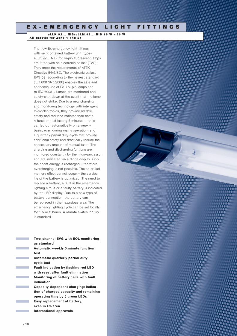
The new Ex-emergency light fittings
with self-contained battery unit, types
eLLK 92… NIB, for bi-pin fluorescent lamps
are fitted with an electronic ballast (EVG).
They meet the requirements of ATEX
Directive 94/9/EC. The electronic ballast
EVG 09, according to the newest standard
(IEC 60079-7:2006) enables the safe and
economic use of G13 bi-pin lamps acc.
to IEC 60081. Lamps are monitored and
safety shut down at the event that the lamp
does not strike. Due to a new charging
and monitoring technology with intelligent
microelectronics, they provide reliable
safety and reduced maintenance costs.
A function test lasting 5 minutes, that is
carried out automatically on a weekly
basis, even during mains operation, and
a quarterly partial duty-cycle test provide
additional safety and drastically reduce the
necessaary amount of manual tests. The
charging and discharging funtions are
monitored constantly by the micro-processor
and are indicated via a diode display. Only
the spent energy is recharged – therefore,
overcharging is not possible. The so-called
memory effect cannot occur – the service
life of the battery is optimized. The need to
replace a battery, a fault in the emergency
lighting circuit or a faulty battery is indicated
by the LED display. Due to a new type of
battery connection, the battery can
be replaced in the hazardous area. The
emergency lighting cycle can be set locally
for 1.5 or 3 hours. A remote switch inquiry
is standard.
eLLK 92. . . N IB/eLLM 92. . . N IB 18 W - 36 WAl l -p last ic for Zone 1 and 21

I Inte l l igent Battery Technology – Safety in Case of Emergency I
C O O P E R C R O U S E - H I N D S G M B H 2.19
Emergency light fittings with
self-contained battery systems
Emergency light fittings with self-
contained battery systems provide the
required emergency lighting from a de-
centralized source and function inde-
pendent of the central system. These
light fittings are particularly economical
when used in extensive plants. Until
now, compared to the centrally opera-
ted and monitored installations, the
disadvantage of the emergency light
fittings with self-con tained battery
systems was that they do not supply
any information on the state of the light
fittings. With the introduction of the
eLLK 92 .... NIB, Cooper Crouse-Hinds
GmbH has now incorporated monito-
ring. Five LEDs supply constant infor -
mation on the charging state, and the
available battery capacity.
Monitoring functions NIB
A novelty is the enlarged self-monito-
ring function with automatic function
and duration tests. For further safety,
all battery cells are permanently moni-
tored. In the event of a fault, the red
LED lights up. Then the battery must be
changed. Resetting is not possible for
safety reasons.
Guarded by a lens, the 5 green LEDs
cotinuously indicate the charging state
and the battery capacity. Charging is
indicated by flashing green LEDs. The
loaded capacity is shown in 20 % steps.
An automatic 5 minute function test is
carried out on a weekly basis. Thereby,
the electronics of the emergency lamp
switches from mains to emergency
operation, while the mains lamp stays
in normal operation. The battery
capacity and also the converter- and
lamp-function is being tested and
possible faults are shown by a flashing
red LED. After removing the fault (p.e.
by lamp change) and a new function
test the fault indication resets auto -
matically.
A partial duty cycle-test (35 min.) is
initiated automatically after approx.
3 months. If the min. operation time
of 30 minutes is not reached, this is
indicated by a flashing red LED. When
the cause of the fault has been elimina-
ted, the fault indication is reset during
the next emergency lighting operation
(manual or automatic) when the
minimum operating time of approx.
30 minutes has been reached.
red LED green LEDsMonitoring Display
✴
Fault/ 81- 61- 41- 21- 0-
Servicing 100 % 80 % 60 % 40 % 20 %
Capacity larger than 40 %, Charging (flashing), no faults
✴
Fault/ 81- 61- 41- 21- 0-
Servicing 100 % 80 % 60 % 40 % 20 %
Capacity 100 %, Charging, Fault after Function or duty cycle
✴LED:
= flashing
= off
= on
1
2
3
4
5
6
7
8
9
10
11
12
2.20 C O O P E R C R O U S E - H I N D S G M B H
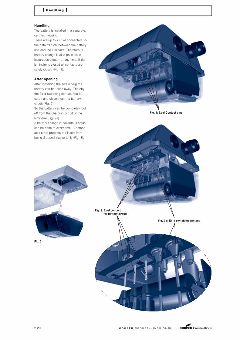
Handling
The battery is installed in a separate,
certified housing.
There are up to 7 Ex-d connectors for
the data transfer between the battery
unit and the luminaire. Therefore, a
battery change is also possible in
hazardous areas – at any time. If the
luminaire is closed all contacts are
safely closed (Fig. 1).
After opening
After loosening the screw plug the
battery can be taken away. Thereby
the Ex-d switching contact first is
cutoff and disconnect the battery
circuit (Fig. 2).
So the battery can be completely cut
off from the charging circuit of the
luminaire (Fig. 2a).
A battery change in hazardous areas
can be done at every time. A detach -
able strap protects the insert from
being dropped inadvertenly (Fig. 3).
Fig. 3
Fig. 1: Ex-d Contact pins
Fig. 2 a: Ex-d switching contact
I Handl ing I
Fig. 2: Ex-d contact for battery circuit

I eLLK 92018/18 NIB I eLLK 92036/36 NIB I eLLM 92018/18 NIB I
C O O P E R C R O U S E - H I N D S G M B H 2.21
Technical data
eLLK 92018/18 NIB ⎮ eLLK 92036/36 NIB ⎮ eLLM 92018/18 NIB
Marking to 94/9/EC II 2 G Ex de mb ib IIC T4 / II 2 D Ex tD A21 IP66 T80 °C
EC-Type Examination Certificate BVS 09 ATEX E 034
IECEx-Certificate of Conformity IECEx BVS 09.0033
Marking to IECEx Ex de mb [ib] IIC T4
Ex tD A21 IP66 T80 °C
Permissible ambient temperature -25 °C to +50 °C (specified data: -5 °C to +35 °C)
Rated voltage 220 - 254 V AC
Rated voltage (option) 110 - 127 V AC
Frequency 50 - 60 Hz
Power factor cos ϕ ≥ 0.95
Circuit EVG with emergency lighting supply
Insulation class I
Lamp cap G13 accd. to IEC 60081
Light efficiency in operation 78 %
Battery Battery set with 7 Ah-NC battery, with LED display
and monitoring via microprocessor
Rated emergency lighting operation 1-lamps can be set on site for an emergency lighting duration of 1.5 or 3 hours
Charging duration > 14 h
Degree of protection accd. EN 60529 IP66
Cable glands/gland plates/enclosure drilling Ex-e cable glands M25 x 1.5 (plastic) for cables from Ø 8 - 17 mm,
Option: M20 x 1.5 metal thread (eLLK 92 NIB)
Enclosure material Glass-fibre reinforced polyester
Protective cover/protective bowl Polycarbonate
eLLK 92018/18 NIB eLLK 92036/36 NIB eLLM 92018/18 NIB
Rated current 0.23 A 0.40 A 0.23 A
Connecting terminals L1, L2, L3, L, N, PE; L1, L2, L3, L, N, PE; L1, L2, L3, L, N, PE;
max. 2 x 6 mm2 max. 2 x 6 mm2 max. 2 x 6 mm2
per terminal per terminal per terminal
Lamp/illuminant 2 x T26 / 18 W (T8) 2 x T26 / 36 W (T8) 2 x T26 / 18 W (T8)
Rated luminous flux1) 2700 lm 6700 lm 2700 lm
Luminous flux in emergency operation (1.5 h, one lamp)1) 1215 lm (90 %) 1507 lm (45 %) 1215 lm (90 %)
Luminous flux in emergency operation (3 h, one lamp)1) 607 lm (45 %) 873 lm (25 %) 607 lm (45 %)
Dimensions (L x W x H) 900 x 188 x 130 mm 1500 x 188 x 130 mm 1205 x 188 x 130 mm
Pole socket Ø 44 x 150 mm
Weight approx. 8.8 kg approx. 12 kg approx. 10.5 kg
1) depends on used lamps
2 x 18 W 2 x 36 W 2 x 18 W
1
2
3
4
5
6
7
8
9
10
11
12

2.22 C O O P E R C R O U S E - H I N D S G M B H
I eLLK 92018/18 NIB I eLLK 92036/36 NIB I eLLM 92018/18 NIB I
Ordering detai ls
Type Terminals Through-wiring Cable Plugs Order No.
single-ended double-ended glands2)
eLLK 92018/18 NIB (2 x 18 W)
1/6-1 1 x 6 x – 2 x M25 x 1.5 1 x blanking 1 2260 879 101
2/6-2 2 x 6 – x 2 x M25 x 1.5 2 x threaded 1 2260 879 103
2/6-2 M1) 2 x 6 – x 4 x M20 x 1.5 3 x threaded 1 2260 879 111
eLLK 92036/36 NIB (2 x 36 W)
1/6-1 1 x 6 x – 2 x M25 x 1.5 1 x blanking 1 2261 879 101
2/6-2 2 x 6 – x 2 x M25 x 1.5 2 x threaded 1 2261 879 103
2/6-2 M1) 2 x 6 – x 4 x M20 x 1.5 3 x threaded 1 2261 879 111
eLLM 92018/18 NIB (2 x 18 W)
2/6-1 1 x 8 x – 1 x M25 – 1 2273 879 101
1) M: with metal thread, without cable gland
2) With dustcover if entry/thread is not closed
Scope of delivery without lamp and fixing accessoires
2 x 18 W 2 x 36 W 2 x 18 W
Accessories
Lamp for luminaire eLLK92... NIB/eLLM92... NIB
Type of lamp Power Luminous flux Order No.
socket/ Light colour
Diameter
Bi-pin socket G13 18 W 1350 lm white 3 2475 900 001
T26/Ø 26 mm (T8)
G13-60081-IEC-2220-1
Bi-pin socket G13 36 W 3350 lm white 3 2475 900 002
T26/Ø 26 mm (T8)
G13-60081-IEC-2420-1
Aura-Ultimate 18 W 1300 lm white 3 2475 900 087
T26/Ø 26 mm (T8) Longlife 36 W 3350 lm white 3 2475 900 088
Socket G13
Aura Super Ex 18 W 1150 lm white 3 2475 900 084
T-HS 26/Ø 26 mm1) 36 W 3000 lm white 3 2475 900 085
Single pin cap Fa6
1) For luminaires eLLK 923../.. and eLLM 923../.. single-pin caps Fa6
110 - 127 V50 - 60 Hz
220 - 254 V50 - 60 Hz
41

I eLLK 92018/18 NIB I eLLK 92036/36 NIB I eLLM 92018/18 NIB I
C O O P E R C R O U S E - H I N D S G M B H 2.23
2 x 18 W 2 x 36 W 2 x 18 W
Accessories
Series eLLK 92... NIB and eLLM 92... NIB
Type Order No.
Hexagon key SW 13 3 2485 000 005
Series eLLM 92018/18 NIB and eLLM 92036/36 NIB
Type Order No.
Single sided through wiring 2/6 with 2 entries M25, incl. terminals and mounting material 2 2218 602 000
Fixing materials eLLK 92... NIB
Type/code Corrosion Qty. Order No.
protection per light fitting
Eye bolt A2 galvanized 2 2 2480 002 000
Hexagon screw S4 stainless steel 2 2 2480 054 000
Ceiling mounting bracket D92 stainless steel 2 2 2480 092 000
incl. screws and washer
Fixing materials
Type/code Corrosion for pipes Outer Ø Qty. Order No.
protection DIN D (mm) per light fitting
Pipe clamp
R12 hot galvanized 11/4” 38 - 42 2 2 2480 462 000
R14 CrNi 11/4” 38 - 42 2 2 2480 464 000
R22 hot galvanized 11/2” 47 - 51 2 2 2480 472 000
R24 CrNi 11/2” 47 - 51 2 2 2480 474 000
R32 hot galvanized 2” 56 - 60 2 2 2480 482 000
R34 CrNi 2” 56 - 60 2 2 2480 484 000
Wall bracket W27 hot galvanized 42.4 1 2 2483 027 000
Luminaire wall suspension 30° hot galvanized 2 2 2480 000 122
incl. screws and washer
Battery
Type Order No.
eLLK 92..., eLLM 92... NIB Battery set type 2710-3 with LED display and micro-processor monitoring, complete 2 2710 904 000
1) For luminaires eLLK 923../.. and eLLM 923../.. with single pin caps Fa6
Metal cable glands M20/M25 see page 8.10.
Complete Mounting Systems see page 2.70 to 2.76.
1
2
3
4
5
6
7
8
9
10
11
12

2.24 C O O P E R C R O U S E - H I N D S G M B H
I eLLK 92018/18 NIB I eLLK 92036/36 NIB I eLLM 92018/18 NIB I
2 x 18 W NIB 2 x 36 W NIB 2 x 18 W NIB
Dim
en
sio
ns i
n m
m
Dimension drawing ⎮ Polar curve
C 0 C90 l/cd/klm
40
80
120
160
200
90
75
60
45
30 15
0 15
30
45
60
75
90
Polar curve
eLLK/eLLM 920. . / . . NIB
in emergency operat ion
C 0 C90 l/cd/klm
40
80
120
160
200
90
75
60
45
30 15
0 15
30
45
60
75
90
Polar curve
eLLK 92018/18 /
eLLK 92036/36 NIB
130 65
188 46
Hexagon SW 13
900
M8, 14 deep
M25
x 1.
5
400 3.5
Hexagon SW 13
1500
M8, 14 deep
M25
x 1.
5
700 3.5
130 65
188 46
130
880
1205
76
188 44
Hexagon SW 13
eLLK 92018/18 NIB
eLLK 92036/36 NIB
eLLM 92018/18 NIB
eLLM 92018/18 NIB
150
33
33150
33
20