ex-a320m-gaming · 2019-03-10 · if any of the above items is damaged or missing, contact your...
TRANSCRIPT

Mot
herb
oard
EX-A320M-GAMING

ii
E13360First EditionAugust 2017
Copyright © 2017 ASUSTeK COMPUTER INC. All Rights Reserved.No part of this manual, including the products and software described in it, may be reproduced, transmitted, transcribed, stored in a retrieval system, or translated into any language in any form or by any means, except documentation kept by the purchaser for backup purposes, without the express written permission of ASUSTeK COMPUTER INC. (“ASUS”).Product warranty or service will not be extended if: (1) the product is repaired, modified or altered, unless such repair, modification of alteration is authorized in writing by ASUS; or (2) the serial number of the product is defaced or missing.ASUS PROVIDES THIS MANUAL “AS IS” WITHOUT WARRANTY OF ANY KIND, EITHER EXPRESS OR IMPLIED, INCLUDING BUT NOT LIMITED TO THE IMPLIED WARRANTIES OR CONDITIONS OF MERCHANTABILITY OR FITNESS FOR A PARTICULAR PURPOSE. IN NO EVENT SHALL ASUS, ITS DIRECTORS, OFFICERS, EMPLOYEES OR AGENTS BE LIABLE FOR ANY INDIRECT, SPECIAL, INCIDENTAL, OR CONSEQUENTIAL DAMAGES (INCLUDING DAMAGES FOR LOSS OF PROFITS, LOSS OF BUSINESS, LOSS OF USE OR DATA, INTERRUPTION OF BUSINESS AND THE LIKE), EVEN IF ASUS HAS BEEN ADVISED OF THE POSSIBILITY OF SUCH DAMAGES ARISING FROM ANY DEFECT OR ERROR IN THIS MANUAL OR PRODUCT.SPECIFICATIONS AND INFORMATION CONTAINED IN THIS MANUAL ARE FURNISHED FOR INFORMATIONAL USE ONLY, AND ARE SUBJECT TO CHANGE AT ANY TIME WITHOUT NOTICE, AND SHOULD NOT BE CONSTRUED AS A COMMITMENT BY ASUS. ASUS ASSUMES NO RESPONSIBILITY OR LIABILITY FOR ANY ERRORS OR INACCURACIES THAT MAY APPEAR IN THIS MANUAL, INCLUDING THE PRODUCTS AND SOFTWARE DESCRIBED IN IT.Products and corporate names appearing in this manual may or may not be registered trademarks or copyrights of their respective companies, and are used only for identification or explanation and to the owners’ benefit, without intent to infringe.
Offer to Provide Source Code of Certain SoftwareThis product contains copyrighted software that is licensed under the General Public License (“GPL”), under the Lesser General Public License Version (“LGPL”) and/or other Free Open Source Software Licenses. Such software in this product is distributed without any warranty to the extent permitted by the applicable law. Copies of these licenses are included in this product.Where the applicable license entitles you to the source code of such software and/or other additional data, you may obtain it for a period of three years after our last shipment of the product, either(1) for free by downloading it from http://support.asus.com/downloador(2) for the cost of reproduction and shipment, which is dependent on the preferred carrier and the location where you want to have it shipped to, by sending a request to:
ASUSTeK Computer Inc.Legal Compliance Dept.15 Li Te Rd.,Beitou, Taipei 112Taiwan
In your request please provide the name, model number and version, as stated in the About Box of the product for which you wish to obtain the corresponding source code and your contact details so that we can coordinate the terms and cost of shipment with you.The source code will be distributed WITHOUT ANY WARRANTY and licensed under the same license as the corresponding binary/object code.This offer is valid to anyone in receipt of this information.ASUSTeK is eager to duly provide complete source code as required under various Free Open Source Software licenses. If however you encounter any problems in obtaining the full corresponding source code we would be much obliged if you give us a notification to the email address [email protected], stating the product and describing the problem (please DO NOT send large attachments such as source code archives, etc. to this email address).
iii
Contents
Safety information ...................................................................................... iv
About this guide ......................................................................................... iv
Package contents ....................................................................................... vi
EX-A320M-GAMING specifications summary .......................................... vi
Chapter 1 Product introductionMotherboard overview ............................................................................. 1-1
Central Processing Unit (CPU) ................................................................ 1-7
System memory ........................................................................................ 1-9
Chapter 2 BIOS informationBIOS setup program ................................................................................. 2-1
I-Cafe ....................................................................................................... 2-2
Main menu ................................................................................................. 2-3
Ai Tweaker ................................................................................................. 2-4
Advanced menu ........................................................................................ 2-6
Monitor menu ............................................................................................ 2-8
Boot menu ................................................................................................. 2-9
Tool menu ................................................................................................ 2-11
Exit menu ................................................................................................. 2-12
AppendixNotices .......................................................................................................A-1
ASUS contact information .......................................................................A-4

iv
Safety information
Electrical safety• To prevent electrical shock hazard, disconnect the power cable from the electrical outlet
before relocating the system.
• When adding or removing devices to or from the system, ensure that the power cables for the devices are unplugged before the signal cables are connected. If possible, disconnect all power cables from the existing system before you add a device.
• Before connecting or removing signal cables from the motherboard, ensure that all power cables are unplugged.
• Seek professional assistance before using an adapter or extension cord. These devices could interrupt the grounding circuit.
• Ensure that your power supply is set to the correct voltage in your area. If you are not sure about the voltage of the electrical outlet you are using, contact your local power company.
• If the power supply is broken, do not try to fix it by yourself. Contact a qualified service technician or your retailer.
Operation safety• Before installing the motherboard and adding components, carefully read all the manuals
that came with the package.
• Before using the product, ensure all cables are correctly connected and the power cables are not damaged. If you detect any damage, contact your dealer immediately.
• To avoid short circuits, keep paper clips, screws, and staples away from connectors, slots, sockets and circuitry.
• Avoid dust, humidity, and temperature extremes. Do not place the product in any area where it may be exposed to moisture.
• Place the product on a stable surface.
• If you encounter technical problems with the product, contact a qualified service technician or your retailer.
About this guideThis user guide contains the information you need when installing and configuring the motherboard.
How this guide is organizedThis guide contains the following parts:
• Chapter1:Productintroduction
This chapter describes the features of the motherboard and the new technology it supports. It includes descriptions of the switches, jumpers, and connectors on the motherboard.
• Chapter2:BIOSinformation
This chapter discusses changing system settings through the BIOS Setup menus.
v
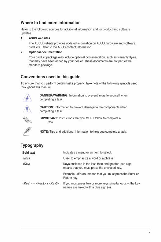
Where to find more informationRefer to the following sources for additional information and for product and software updates.
1. ASUS websites
The ASUS website provides updated information on ASUS hardware and software products. Refer to the ASUS contact information.
2. Optional documentation
Your product package may include optional documentation, such as warranty flyers, that may have been added by your dealer. These documents are not part of the standard package.
Conventions used in this guideTo ensure that you perform certain tasks properly, take note of the following symbols used throughout this manual.
DANGER/WARNING: Information to prevent injury to yourself when completing a task.
CAUTION: Information to prevent damage to the components when completing a task
IMPORTANT: Instructions that you MUST follow to complete a task.
NOTE: Tips and additional information to help you complete a task.
Typography
Bold text Indicates a menu or an item to select.
Italics Used to emphasize a word or a phrase.
<Key> Keys enclosed in the less-than and greater-than sign means that you must press the enclosed key.
Example: <Enter> means that you must press the Enter or Return key.
<Key1> + <Key2> + <Key3> If you must press two or more keys simultaneously, the key names are linked with a plus sign (+).

vi
EX-A320M-GAMING specifications summary
(continued on the next page)
Package contentsCheck your motherboard package for the following items.
Motherboard ASUS EX-A320M-GAMING motherboard
Accessories
2 x Serial ATA 6.0Gb/s cables1 x I/O Shield1 x M.2 screw package
Application DVD 1 x Support DVD
Documentation User Guide
If any of the above items is damaged or missing, contact your retailer.
CPU
AM4 socket for AMD® Ryzen™/7th Generation A-series/Athlon™ Processors
Supports 14nm CPU
Supports CPU up to 8 cores** Due to CPU limitation, CPU cores supported varies by processor.
** Refer to www.asus.com for the AMD® CPU support list.
Chipset AMD® A320 Chipset
Memory
AMDRyzen™processors:4 x DIMMs, max. 64GB, DDR4 2666/2400/2133 MHz,ECC, non-ECC, un-
buffered memory
AMD 7thGenerationA-series/Athlon™processors:4 x DIMMs, max. 64GB, DDR4 2400/2133 MHz, ECC,non-ECC, un-buffered
memory
Dual-channel memory architecture* Refer to www.asus.com for the latest Memory QVL (Qualified Vendors List).
Graphics
Integrated AMD Radeon™ R Series Graphics in the 7th Generation A-Series APU
Multi-VGA output support: HDMI, DVI-D ports- Supports HDMI 1.4b with max. resolution 4096 x 2160 @24Hz- Supports DVI-D with max. resolution up to 1920 x 1200 @60Hz
Maximum shared memory of 2048 MB
Expansion slots
AMDRyzen™processors:1 x PCI Express 3.0/2.0 x16 slot (max. @x16 mode)
AMD 7thGenerationA-series/Athlon™processors:1 x PCI Express 3.0/2.0 x16 slot (max. @x8 mode)
AMDA320Chipset:1 x PCI Express 2.0 x4 slot (max. @x2 mode)1 x PCI Express 2.0 x1 slot
AudioRealtek® ALC 887-VD2 8-Channel High Definition Audio CODEC* Use a chassis with HD audio module in the front panel to support an 8-channel audio
output.
vii
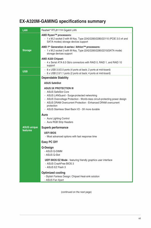
EX-A320M-GAMING specifications summary
LAN Realtek® RTL8111H Gigabit LAN
Storage
AMDRyzen™processors:- 1 x M.2 socket 3 with M Key, Type 2242/2260/2280/22110 (PCIE 3.0 x4 and
SATA modes) storage devices support
AMD 7thGenerationA-series/Athlon™processors:- 1 x M.2 socket 3 with M Key, Type 2242/2260/2280/2210(SATA mode)
storage devices support
AMDA320Chipset:- 4 x Serial ATA 6.0 Gb/s connectors with RAID 0, RAID 1, and RAID 10
support
USB- 6 x USB 3.0/2.0 ports (4 ports at back; 2 ports at mid-board) - 6 x USB 2.0/1.1 ports (2 ports at back; 4 ports at mid-board)
ASUS unique features
Dependable Stability
ASUS SafeSlot
ASUS 5X PROTECTION III - ASUS SafeSlot Core- ASUS LANGuard - Surge-protected networking- ASUS Overvoltage Protection - World-class circuit-protecting power design- ASUS DRAM Overcurrent Protection - Enhanced DRAM overcurrent
protection- ASUS Stainless Steel Back I/O - 3X more durable
Aura- Aura Lighting Control- Aura RGB Strip Headers
Superb performance
UEFI BIOS - Most advanced options with fast response time
Easy PC DIY
Q-Design- ASUS Q-DIMM- ASUS Q-Slot
UEFI BIOS EZ Mode - featuring friendly graphics user interface - ASUS CrashFree BIOS 3 - ASUS EZ Flash 3
Optimized cooling- Stylish Fanless Design: Chipset Heat-sink solution- ASUS Fan Xpert
(continued on the next page)

viii
EX-A320M-GAMING specifications summary
Specifications are subject to change without notice.
Rear panel I/O ports
1 x PS/2 keyboard (purple)
1 x PS/2 mouse port (green)
1 x HDMI port
1 x DVI-D port
1 x LAN (RJ-45) port
4 x USB 3.0/ 2.0 ports
2 x USB 2.0/ 1.1 ports
3 x Audio jacks support 8-channel audio output
Internal connectors
2 x USB 2.0/ 1.1 connectors support additional 4 USB 2.0/ 1.1 ports
1 x USB 3.0 connector support additional 2 USB 3.0 ports
4 x SATA 6.0Gb/s connectors
1 x M.2 Socket 3 for M Key, type 2242/2260/2280/22110 devices
1 x 14-1 pin TPM connector
1 x COM connector
1 x CPU fan connector
1 x Chassis fan connector
1 x AIO Pump header
1 x Front panel audio connector
1 x 24-pin EATX power connector
1 x 8-pin EATX 12V power connector
1 x Speaker header
1 x Clear RTC RAM (2 pin)
1 x System panel connector
1 x RGB header
BIOS features
128 Mb Flash ROM, UEFI AMI BIOS, PnP, DMI3.0, WfM2.0, SM BIOS 3.0, ACPI 6.1, Multi-language BIOS, ASUS EZ Flash 3, ASUS CrashFree BIOS 3, I-CAFE, Last Modified log, F12 PrintScreen, ASUS DRAM SPD (Serial Presence Detect) memory information, F6 Qfan Control
Manageability WfM 2.0, DMI 3.0, WOL by PME, PXE
Support DVD
Drivers
ASUS Utilities
ASUS Update
OS support Windows® 10 (64-bit)
Form factor uATX Form Factor, 9.6” x 9.6” (24.4 cm x 24.4 cm)

ASUS EX-A320M-GAMING 1-1
Product introduction 1Motherboard overview
• Unplugthepowercordfromthewallsocketbeforetouchinganycomponent.
• Beforehandlingcomponents,useagroundedwriststraportouchasafelygroundedobjectorametalobject,suchasthepowersupplycase,toavoiddamagingthemduetostaticelectricity.
• Beforeyouinstallorremoveanycomponent,ensurethattheATXpowersupplyisswitchedofforthepowercordisdetachedfromthepowersupply.Failuretodosomaycauseseveredamagetothemotherboard,peripherals,orcomponents.
• Unplugthepowercordbeforeinstallingorremovingthemotherboard.Failuretodosocancauseyouphysicalinjuryanddamagetomotherboardcomponents.
Place this side towards
the rear of the chassis
ScantheQRcodetogetthedetailedpindefinitions.
EX-A320M-GAMINGPCIEX16
PCIEX4
PCIEX1
SPEAKER
CLRTC F_PANEL
USB56USB34RGB_HEADER
AAFP
COM
EATX12V
EA
TXP
WR
CPU_FAN
CHA_FAN
AIO_PUMP
BATTERY
SuperI/O
ALC887
AURA
DIGI+EPU
24.4
cm(9
.6in
)
24.4cm(9.6in)
AMDA320
DD
R4
DIM
M_A
1 (6
4bit,
288
-pin
mod
ule)
SO
CK
ET
AM
4
228022110 2260 2242
M.2
(SO
CK
ET3
)
PCIE SATA
M.2(SOCKET3)
X4 V
DD
R4
DIM
M_A
2 (6
4bit,
288-
pin
mod
ule)
DD
R4
DIM
M_B
1 (6
4bit,
288
-pin
mod
ule)
DD
R4
DIM
M_B
2 (6
4bit,
288
-pin
mod
ule)
AUDIO
KBMS
DV
I
HDMI
LAN_USB12
U31G1_34
U31G1_56
128MbBIOS
SATA6G_3
SA
TA6G
_4
SATA6G_1 SATA6G_2
Realtek®
8111H
TPM U31G1_12
131 42
1
589
6
7
2
15
13 12 1114
16
17
15
10

1-2 Chapter 1: Product introduction
CPU and chassis fan connectors (4-pin CPU_FAN, 4-pin CHA_FAN)
Connectthefancablestothefanconnectorsonthemotherboard,ensuringthattheblackwireofeachcablematchesthegroundpinoftheconnector.
Donotforgettoconnectthefancablestothefanconnectors.Insufficientairflowinsidethesystemmaydamagethemotherboardcomponents.Thesearenotjumpers!Donotplacejumpercapsonthefanconnectors!TheCPU_FANconnectorsupportsaCPUfanofmaximum1A(12W)fanpower.
ATX power connectors (24-pin EATXPWR, 8-pin EATX12V)
TheseconnectorsareforATXpowersupplyplugs.Thepowersupplyplugsaredesignedtofittheseconnectorsinonlyoneorientation.Findtheproperorientationandpushdownfirmlyuntiltheconnectorscompletelyfit.
• Forafullyconfiguredsystem,werecommendthatyouuseapowersupplyunit(PSU)thatcomplieswithATX12VSpecification2.0(orlaterversion)andprovidesaminimumpowerof350W.
• DONOTforgettoconnectthe4-pin/8-pinEATX+12Vpowerplug.Otherwise,thesystemwillnotbootup.
• WerecommendthatyouuseaPSUwithhigherpoweroutputwhenconfiguringasystemwithmorepower-consumingdevicesorwhenyouintendtoinstalladditionaldevices.Thesystemmaybecomeunstableormaynotbootupifthepowerisinadequate.
• Ifyouareuncertainabouttheminimumpowersupplyrequirementforyoursystem,refertotheRecommendedPowerSupplyWattageCalculatorathttp://support.asus.com/PowerSupplyCalculator/PSCalculator.aspx?SLanguage=en-usfordetails.
AMD AM4 CPU socket
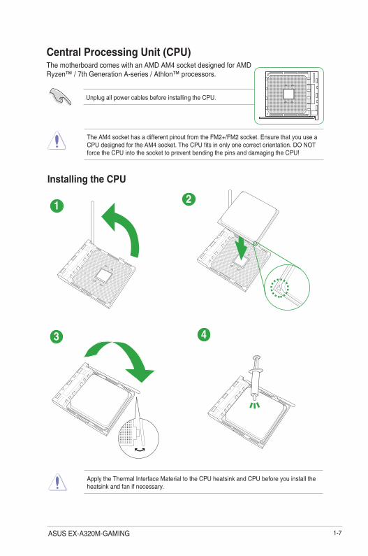
ThismotherboardcomeswithanAMDAM4socketdesignedforAMDRyzen™/7thGenerationA-series/Athlon™Processors.
Formoredetails,refertoCentral Processing Unit (CPU).
DDR4 DIMM slots
Install2GB,4GB,8GB,and16GBECCandnon-ECCDDR4DIMMsintotheseDIMMsockets.
Formoredetails,refertoSystem memory.
AMD® A320 Serial ATA 6.0Gb/s connectors (7-pin SATA6G_1~4)
TheseconnectorsconnecttoSerialATA6.0Gb/sharddiskdrivesviaSerialATA6.0Gb/ssignalcables.

ASUS EX-A320M-GAMING 1-3
Speaker connector (4-pin SPEAKER)
This4-pinconnectorisforthechassis-mountedsystemwarningspeaker.Thespeakerallowsyoutohearsystembeepsandwarnings.
System panel connector (10-1 pin F_PANEL)
Thisconnectorsupportsseveralchassis-mountedfunctions.
Clear RTC RAM (2-pin CLRTC)
ThisheaderallowsyoutocleartheCMOSRTCRAMdataofthesystemsetupinformationsuchasdate,time,andsystempasswords.
ToerasetheRTCRAM:
1. TurnOFFthecomputerandunplugthepowercord.
2. Useametalobjectsuchasascrewdrivertoshortthetwopins.
3. PlugthepowercordandturnONthecomputer.
4. Holddownthe<Del>keyduringthebootprocessandenterBIOSsetuptore-enterdata.
CLRTC
+3V
_BA
TG
ND
PIN 1
Ifthestepsabovedonothelp,removetheonboardbatteryandshortthetwopinsagaintocleartheCMOSRTCRAMdata.AfterclearingtheCMOS,reinstallthebattery.
USB 3.0 connector (20-1 pin U31G1_12)
ConnectaUSB3.0moduletothisconnectorforadditionalUSB3.0frontorrearpanelports.ThisconnectorcomplieswithUSB3.0specificationsandprovidefasterdatatransferspeedsofupto5Gbps,fasterchargingtimeforUSB-chargeabledevices,optimizedpowerefficiency,andbackwardcompatibilitywithUSB2.0.
USB 2.0 connectors (10-1 pin USB34, USB56)
ConnectaUSBmodulecabletoanyoftheseconnectors,theninstallthemoduletoaslotopeningatthebackofthesystemchassis.TheseUSBconnectorscomplywithUSB2.0specificationsandsupportsupto480Mbpsconnectionspeed.
TPM connector (14-1 pin TPM)
ConnectaTrustedPlatformModule(TPM)systemtothisconnectortoenhancenetworksecurity,protectdigitalidentities,andensureplatformintegrity.
TPM
PIN 1
+3VSBS_PCIRST#_TBD
GNDC_PCICLK_TPM
+3V+3V
F_CLKRUNF_SERIRQF_FRAME#F_LAD3F_LAD2F_LAD1F_LAD0
1-4 Chapter 1: Product introduction
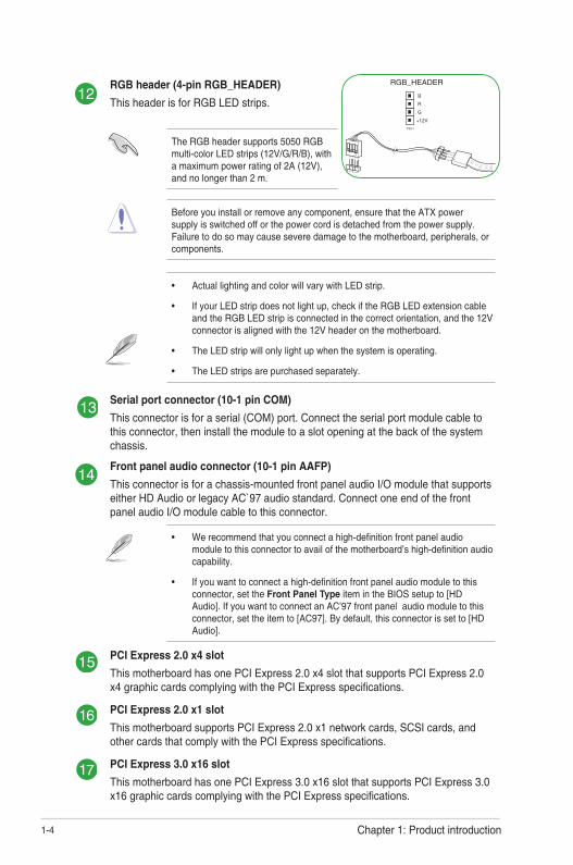
RGB header (4-pin RGB_HEADER)
ThisheaderisforRGBLEDstrips.
TheRGBheadersupports5050RGBmulti-colorLEDstrips(12V/G/R/B),withamaximumpowerratingof2A(12V),andnolongerthan2m.
Beforeyouinstallorremoveanycomponent,ensurethattheATXpowersupplyisswitchedofforthepowercordisdetachedfromthepowersupply.Failuretodosomaycauseseveredamagetothemotherboard,peripherals,orcomponents.
• ActuallightingandcolorwillvarywithLEDstrip.
• IfyourLEDstripdoesnotlightup,checkiftheRGBLEDextensioncableandtheRGBLEDstripisconnectedinthecorrectorientation,andthe12Vconnectorisalignedwiththe12Vheaderonthemotherboard.
• TheLEDstripwillonlylightupwhenthesystemisoperating.
• TheLEDstripsarepurchasedseparately.
Serial port connector (10-1 pin COM)
Thisconnectorisforaserial(COM)port.Connecttheserialportmodulecabletothisconnector,theninstallthemoduletoaslotopeningatthebackofthesystemchassis.
Front panel audio connector (10-1 pin AAFP)
Thisconnectorisforachassis-mountedfrontpanelaudioI/OmodulethatsupportseitherHDAudioorlegacyAC`97audiostandard.ConnectoneendofthefrontpanelaudioI/Omodulecabletothisconnector.
• Werecommendthatyouconnectahigh-definitionfrontpanelaudiomoduletothisconnectortoavailofthemotherboard’shigh-definitionaudiocapability.
• Ifyouwanttoconnectahigh-definitionfrontpanelaudiomoduletothisconnector,settheFront Panel TypeitemintheBIOSsetupto[HDAudio].IfyouwanttoconnectanAC’97frontpanelaudiomoduletothisconnector,settheitemto[AC97].Bydefault,thisconnectorissetto[HDAudio].
PCI Express 2.0 x4 slot
ThismotherboardhasonePCIExpress2.0x4slotthatsupportsPCIExpress2.0x4graphiccardscomplyingwiththePCIExpressspecifications.
PCI Express 2.0 x1 slot
ThismotherboardsupportsPCIExpress2.0x1networkcards,SCSIcards,andothercardsthatcomplywiththePCIExpressspecifications.
PCI Express 3.0 x16 slot
ThismotherboardhasonePCIExpress3.0x16slotthatsupportsPCIExpress3.0x16graphiccardscomplyingwiththePCIExpressspecifications.
PIN 1
+12V
G
R
B
RGB_HEADER
ASUS EX-A320M-GAMING 1-5
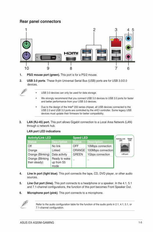
1. PS/2 mouse port (green).ThisportisforaPS/2mouse.
2. USB 3.0 ports.These9-pinUniversalSerialBus(USB)portsareforUSB3.0/2.0devices.
• USB3.0devicescanonlybeusedfordatastorage.
• WestronglyrecommendthatyouconnectUSB3.0devicestoUSB3.0portsforfasterandbetterperformancefromyourUSB3.0devices.
• DuetothedesignoftheIntel®200serieschipset,allUSBdevicesconnectedtotheUSB2.0andUSB3.0portsarecontrolledbythexHCIcontroller.SomelegacyUSBdevicesmustupdatetheirfirmwareforbettercompatibility.
3. LAN (RJ-45) port.ThisportallowsGigabitconnectiontoaLocalAreaNetwork(LAN)throughanetworkhub.
Rear panel connectors
4. Line In port (light blue).Thisportconnectsthetape,CD,DVDplayer,orotheraudiosources.
5. Line Out port (lime).Thisportconnectstoaheadphoneoraspeaker.Inthe4.1,5.1and7.1-channelconfigurations,thefunctionofthisportbecomesFrontSpeakerOut.
6. Microphone port (pink).Thisportconnectstoamicrophone.
Refertotheaudioconfigurationtableforthefunctionoftheaudioportsin2.1,4.1,5.1,or7.1-channelconfiguration.
Activity/Link LED Speed LEDStatus Description Status DescriptionOff Nolink OFF 10MbpsconnectionOrange Linked ORANGE 100MbpsconnectionOrange(Blinking) Dataactivity GREEN 1GbpsconnectionOrange(Blinkingthensteady)
ReadytowakeupfromS5mode
_ _
LAN port
Speed LED
Activity Link LED
LAN port LED indications
1 3
710
2 4 5
689
1-6 Chapter 1: Product introduction
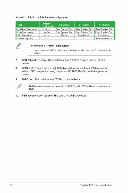
Toconfigurea7.1-channelaudiooutput:
UseachassiswithHDaudiomoduleinthefrontpaneltosupporta7.1-channelaudiooutput.
7. USB 2.0 port.This9-pinUniversalSerialBus2.0(USB2.0)portisforaUSB2.0device.
8. HDMI port. ThisportisforaHigh-DefinitionMultimediaInterface(HDMI)connector,andisHDCPcompliantallowingplaybackofHDDVD,Blu-Ray,andotherprotectedcontent.
9. DVI-D port.ThisportisforanyDVI-Dcompatibledevice.
DVI-DcannotbeconvertedtooutputfromRGBSignaltoCRTandisnotcompatiblewithDVI-I.
10. PS/2 keyboard port (purple).ThisportisforaPS/2keyboard.
Audio 2.1, 4.1, 5.1, or 7.1-channel configuration
PortHeadset
2.1-channel4.1-channel 5.1-channel 7.1-channel
LightBlue(Rearpanel) LineIn RearSpeakerOut RearSpeakerOut RearSpeakerOutLime(Rearpanel) LineOut FrontSpeakerOut FrontSpeakerOut FrontSpeakerOutPink(Rearpanel) MicIn MicIn Bass/Center Bass/CenterLime(Frontpanel) - - - SideSpeakerOut
ASUS EX-A320M-GAMING 1-7
TheAM4sockethasadifferentpinoutfromtheFM2+/FM2socket.EnsurethatyouuseaCPUdesignedfortheAM4socket.TheCPUfitsinonlyonecorrectorientation.DONOTforcetheCPUintothesockettopreventbendingthepinsanddamagingtheCPU!
Central Processing Unit (CPU)ThemotherboardcomeswithanAMDAM4socketdesignedforAMDRyzen™/7thGenerationA-series/Athlon™processors.
UnplugallpowercablesbeforeinstallingtheCPU.
Installing the CPU
ApplytheThermalInterfaceMaterialtotheCPUheatsinkandCPUbeforeyouinstalltheheatsinkandfanifnecessary.
1
3
2
4

1-8 Chapter 1: Product introduction
Installing the CPU heatsink and fan assembly
Type 2
Type 1
1
1
3
2
2
4
Removethescrewsandtheretentionmoduleonly.Donotremovetheplateonthebottom.

ASUS EX-A320M-GAMING 1-9
System memory
OverviewThismotherboardcomeswithfourDoubleDataRate4(DDR4)DualInlineMemoryModule(DIMM)sockets.ThefigureillustratesthelocationoftheDDR4DIMMsockets:
Channel Sockets
ChannelA DIMM_A1&DIMM_A2ChannelB DIMM_B1&DIMM_B2
• YoumayinstallvaryingmemorysizesinChannelAandChannelB.Thesystemmapsthetotalsizeofthelower-sizedchannelforthedual-channelconfiguration.Anyexcessmemoryfromthehigher-sizedchannelisthenmappedforsingle-channeloperation.
• AlwaysinstallDIMMswiththesameCASlatency.Foroptimalcompatibility,werecommendthatyouinstallmemorymodulesofthesameversionordatecode(D/C)fromthesamevendor.Checkwiththeretailertogetthecorrectmemorymodules.
• Forsystemstability,useamoreefficientmemorycoolingsystemtosupportafullmemoryload(4DIMMs).
• Refertowww.asus.comforthelatestMemoryQVL(QualifiedVendorsList)
DIMM_A1DIMM_A2
DIMM_B1DIMM_B2
Recommended memory configurations

1-10 Chapter 1: Product introduction
Installing a DIMM
1 2
To remove a DIMM
B
A
B
A
A
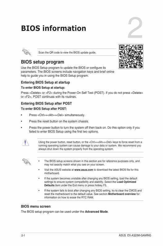
BIOS information 2Scan the QR code to view the BIOS update guide.
BIOS setup programUse the BIOS Setup program to update the BIOS or configure its parameters. The BIOS screens include navigation keys and brief online help to guide you in using the BIOS Setup program.
Entering BIOS Setup at startupToenterBIOSSetupatstartup:
Press <Delete> or <F2> during the Power-On Self Test (POST). If you do not press <Delete> or <F2>, POST continues with its routines.
Entering BIOS Setup after POSTToenterBIOSSetupafterPOST:
• Press <Ctrl>+<Alt>+<Del> simultaneously.
• Press the reset button on the system chassis.
• Press the power button to turn the system off then back on. Do this option only if you failed to enter BIOS Setup using the first two options.
Using the power button, reset button, or the <Ctrl>+<Alt>+<Del> keys to force reset from a running operating system can cause damage to your data or system. We recommend you always shut down the system properly from the operating system.
• The BIOS setup screens shown in this section are for reference purposes only, and may not exactly match what you see on your screen.
• Visit the ASUS website at www.asus.com to download the latest BIOS file for this motherboard.
• If the system becomes unstable after changing any BIOS setting, load the default settings to ensure system compatibility and stability. Select the Load Optimized Defaults item under the Exit menu or press hotkey F5.
• If the system fails to boot after changing any BIOS setting, try to clear the CMOS and reset the motherboard to the default value. See section Motherboard overview for information on how to erase the RTC RAM.
BIOS menu screenThe BIOS setup program can be used under the Advanced Mode.
ASUS EX-A320M-GAMING2-1
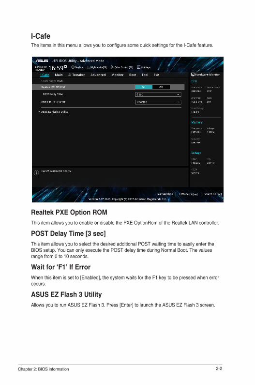
I-CafeThe items in this menu allows you to configure some quick settings for the I-Cafe feature.
Realtek PXE Option ROMThis item allows you to enable or disable the PXE OptionRom of the Realtek LAN controller.
POST Delay Time [3 sec]This item allows you to select the desired additional POST waiting time to easily enter the BIOS setup. You can only execute the POST delay time during Normal Boot. The values range from 0 to 10 seconds.
Wait for ‘F1’ If ErrorWhen this item is set to [Enabled], the system waits for the F1 key to be pressed when error occurs.
ASUS EZ Flash 3 UtilityAllows you to run ASUS EZ Flash 3. Press [Enter] to launch the ASUS EZ Flash 3 screen.
2-2Chapter 2: BIOS information
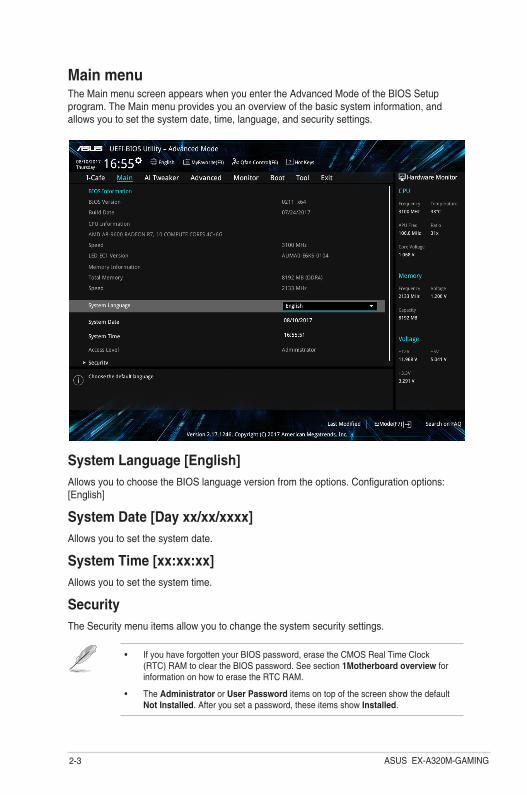
System Language [English]Allows you to choose the BIOS language version from the options. Configuration options: [English]
System Date [Day xx/xx/xxxx]Allows you to set the system date.
SystemTime[xx:xx:xx]Allows you to set the system time.
SecurityThe Security menu items allow you to change the system security settings.
• If you have forgotten your BIOS password, erase the CMOS Real Time Clock (RTC) RAM to clear the BIOS password. See section 1Motherboard overview for information on how to erase the RTC RAM.
• The Administrator or User Password items on top of the screen show the default Not Installed. After you set a password, these items show Installed.
Main menuThe Main menu screen appears when you enter the Advanced Mode of the BIOS Setup program. The Main menu provides you an overview of the basic system information, and allows you to set the system date, time, language, and security settings.
ASUS EX-A320M-GAMING2-3

Ai TweakerThe Extreme Tweaker menu items allow you to configure overclocking-related items.
Be cautious when changing the settings of the Extreme Tweaker menu items. Incorrect field values can cause the system to malfunction
Ai Overclock TunerAllows you to select the CPU overclocking options to achieve the desired CPU internal frequency. Configuration options:
Memory FrequencyThis item allows you to set the memory operating frequency. The configurable options vary with the BCLK (base clock) frequency setting. Select the auto mode to apply the optimized setting
APU MultiplierAllows you to set the multiplier between the APU Core Clock and the APU Bus Frequency. Use the <+> and <-> keys to adjust the value. You can also key in the desired value using the numeric keypad.
EPU Power Saving ModeAllows you to enable or disable the EPU power saving function.
2-4Chapter 2: BIOS information
DRAM Timing ControlThe sub-items in this menu allow you to set the DRAM timing control features. Use the <+> and <-> keys to adjust the value. To restore the default setting, type [auto] using the keyboard and press <Enter>.
TDP ConfigurationThis item allows you to configure TDP.
DIGI+ VRMThe subitems in this menu allows you to configure the DIGI+VRM settings.
VDDCR CPU VoltageThis item allows you to configure the amount of voltage fed to the CPU cores. Increase the voltage when setting a high Core Frequency value.
VDDCR SOC VoltageAllows you to set the VDDCR SOC Voltage. Configuration options: [Auto] [Manual] [Offset].
DRAM Voltage [Auto]This item allows you to set the voltage for the DRAM. Use the <+> and <-> keys to adjust the value.
1.05V SB Voltage [Auto]This item allows you to set the voltage for the 1.05V SB voltage. Use the <+> and <-> keys to adjust the value. The values range from 1.05V to 1.1V with a 0.05V interval.
2.5V SB Voltage [Auto]This item allows you to set the voltage for the 2.5V SB voltage. Use the <+> and <-> keys to adjust the value. The values range from 2.5V to 2.55V with a 0.05V interval.
VDDP VoltageThis item allows you to set the voltage for the VDDP voltage. Use the <+> and <-> keys to adjust the value. The values range from 1.05V to 1.2V with a 0.05V interval.
CPU 1.80V VoltageThis item allows you to set the voltage for the APU 1.80V voltage. Use the <+> and <-> keys to adjust the value. The values range from 1.80V to 1.85V with a 0.005 interval.
VTTDDR VoltageThis item allows you to set the voltage for the VTTDDR voltage. Use the <+> and <-> keys to adjust the value. The values range from 0.600V to 1/2VDDQ+0.2V with a 0.005V interval.
VPP_MEM VoltageThis item allows you to set the voltage for the VPP_MEM voltage. Use the <+> and <-> keys to adjust the value.
ASUS EX-A320M-GAMING2-5

Advanced menuThe Advanced menu items allow you to change the settings for the CPU and other system devices.
Be cautious when changing the settings of the Advanced menu items. Incorrect field values can cause the system to malfunction.
AMD fTPM configurationAllows you to select the TPM device. You can select the Firmware TPM to enable the AMD CPU fTPM or select Discrete TPM to disable the AMD CPU fTPM.
CPU ConfigurationThe items in this menu show the CPU-related information that the BIOS automatically detects.
NB ConfigurationThe items in this menu allow you to adjust the PCH PCI Express speed.
PCH-FW ConfigurationThe items in this menu allows you to configure the management engine technology settings.
SATA ConfigurationWhile entering Setup, the BIOS automatically detects the presence of SATA devices. The SATA Port items show Not Present if no SATA device is installed to the corresponding SATA port.
Onboard Devices ConfigurationThe items in this menu allow you to configure the onboard devices.
APM ConfigurationThe items in this menu allow you to configure the advanced power management settings.
2-6Chapter 2: BIOS information
Network Stack ConfigurationThe items in this menu allow you to configure the network stack settings.
HDD/SSD SMART InformationThis menu displays the SMART information of the connected devices.
USB ConfigurationThe items in this menu allow you to change the USB-related features.
ASUS EX-A320M-GAMING2-7
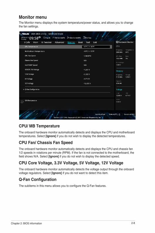
Monitor menuThe Monitor menu displays the system temperature/power status, and allows you to change the fan settings.
CPU/ MB TemperatureThe onboard hardware monitor automatically detects and displays the CPU and motherboard temperatures. Select [Ignore] if you do not wish to display the detected temperatures.
CPU Fan/ Chassis Fan SpeedThe onboard hardware monitor automatically detects and displays the CPU and chassis fan 1/2 speeds in rotations per minute (RPM). If the fan is not connected to the motherboard, the field shows N/A. Select [Ignore] if you do not wish to display the detected speed.
CPU Core Voltage, 3.3V Voltage, 5V Voltage, 12V VoltageThe onboard hardware monitor automatically detects the voltage output through the onboard voltage regulators. Select [Ignore] if you do not want to detect this item.
Q-Fan ConfigurationThe subitems in this menu allows you to configure the Q-Fan features.
2-8Chapter 2: BIOS information
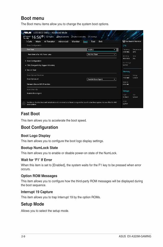
Boot menuThe Boot menu items allow you to change the system boot options.
Fast BootThis item allows you to accelerate the boot speed.
Boot Configuration
Boot Logo DisplayThis item allows you to configure the boot logo display settings.
Bootup NumLock StateThis item allows you to enable or disable power-on state of the NumLock.
Wait for ‘F1’ If ErrorWhen this item is set to [Enabled], the system waits for the F1 key to be pressed when error occurs.
Option ROM MessagesThis item allows you to configure how the third-party ROM messages will be displayed during the boot sequence.
Interrupt 19 CaptureThis item allows you to trap Interrupt 19 by the option ROMs.
Setup ModeAllows you to select the setup mode.
ASUS EX-A320M-GAMING2-9

Secure BootAllows you to configure the Windows® Secure Boot settings and manage its keys to protect the system from unauthorized access and malwares during POST.
Boot Option PrioritiesThese items specify the boot device priority sequence from the available devices. The number of device items that appears on the screen depends on the number of devices installed in the system.
• To access Windows® OS in Safe Mode, press <F8 > after POST (Windows® 8 not supported).
• To select the boot device during system startup, press <F8> when ASUS Logo appears.
Boot OverrideThese items displays the available devices. The number of device items that appears on the screen depends on the number of devices installed in the system. Click an item to start booting from the selected device.
2-10Chapter 2: BIOS information
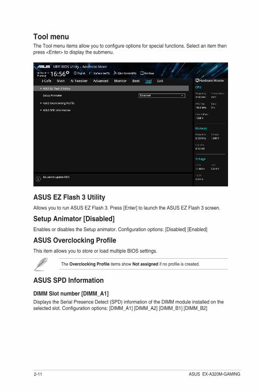
Tool menuThe Tool menu items allow you to configure options for special functions. Select an item then press <Enter> to display the submenu.
ASUS EZ Flash 3 UtilityAllows you to run ASUS EZ Flash 3. Press [Enter] to launch the ASUS EZ Flash 3 screen.
Setup Animator [Disabled]Enables or disables the Setup animator. Configuration options: [Disabled] [Enabled]
ASUS Overclocking ProfileThis item allows you to store or load multiple BIOS settings.
The Overclocking Profile items show Not assigned if no profile is created.
ASUS SPD Information
DIMM Slot number [DIMM_A1] Displays the Serial Presence Detect (SPD) information of the DIMM module installed on the selected slot. Configuration options: [DIMM_A1] [DIMM_A2] [DIMM_B1] [DIMM_B2]
ASUS EX-A320M-GAMING2-11

Load Optimized DefaultsThis option allows you to load the default values for each of the parameters on the Setup menus. When you select this option or if you press <F5>, a confirmation window appears. Select OK to load the default values.
Save Changes & ResetOnce you are finished making your selections, choose this option from the Exit menu to ensure the values you selected are saved. When you select this option or if you press <F10>, a confirmation window appears. Select OK to save changes and exit.
Discard Changes and ExitThis option allows you to exit the Setup program without saving your changes. When you select this option or if you press <Esc>, a confirmation window appears. Select OK to discard changes and exit.
Launch EFI Shell from USB drivesThis option allows you to attempt to launch the EFI Shell application (shellx64.efi) from one of the available USB devices.
Exit menuThe Exit menu items allow you to load the optimal default values for the BIOS items, and save or discard your changes to the BIOS items.
2-12Chapter 2: BIOS information

AppendixNotices
Federal Communications Commission StatementThis device complies with Part 15 of the FCC Rules. Operation is subject to the following two conditions:
• This device may not cause harmful interference.
• This device must accept any interference received including interference that may cause undesired operation.
This equipment has been tested and found to comply with the limits for a Class B digital device, pursuant to Part 15 of the FCC Rules. These limits are designed to provide reasonable protection against harmful interference in a residential installation. This equipment generates, uses and can radiate radio frequency energy and, if not installed and used in accordance with manufacturer’s instructions, may cause harmful interference to radio communications. However, there is no guarantee that interference will not occur in a particular installation. If this equipment does cause harmful interference to radio or television reception, which can be determined by turning the equipment off and on, the user is encouraged to try to correct the interference by one or more of the following measures:
• Reorient or relocate the receiving antenna.
• Increase the separation between the equipment and receiver.
• Connect the equipment to an outlet on a circuit different from that to which the receiver is connected.
• Consult the dealer or an experienced radio/TV technician for help.
The use of shielded cables for connection of the monitor to the graphics card is required toassurecompliancewithFCCregulations.Changesormodificationstothisunitnotexpressly approved by the party responsible for compliance could void the user’s authority to operate this equipment.
ASUS EX-A320M-GAMING A-1

VCCI:JapanComplianceStatement
Class B ITE
KC:KoreaWarningStatement
Compliance Statement of Innovation, Science and Economic Development Canada (ISED)This Class B digital apparatus complies with Canadian ICES-003, RSS-210, and CAN ICES-3(B)/NMB-3(B).
This device complies with Industry Canada license exempt RSS standard(s). Operation is subject to the following two conditions: (1) this device may not cause interference, and (2) this device must accept any interference, including interference that may cause undesired operation of the device.
Déclaration de conformité de Innovation, Sciences et Développement économique Canada (ISED)Cet appareil numérique de classe B est conforme aux normes canadiennes ICES-003, RSS-210 et CAN ICES-3(B)/NMB-3(B).
Cet appareil est conforme aux normes CNR exemptes de licence d’Industrie Canada. Le fonctionnement est soumis aux deux conditions suivantes : (1) cet appareil ne doit pas provoquer d’interférences et (2) cet appareil doit accepter toute interférence, y compris celles susceptibles de provoquer un fonctionnement non souhaité de l’appareil.
A-2 Appendices
REACHComplying with the REACH (Registration, Evaluation, Authorisation, and Restriction of Chemicals) regulatory framework, we published the chemical substances in our products at ASUS REACH website at http://csr.asus.com/english/REACH.htm.
DO NOT throw the motherboard in municipal waste. This product has been designed to enable proper reuse of parts and recycling. This symbol of the crossed out wheeled bin indicates that the product (electrical and electronic equipment) should not be placed in municipal waste. Check local regulations for disposal of electronic products.
DO NOT throw the mercury-containing button cell battery in municipal waste. This symbol of the crossed out wheeled bin indicates that the battery should not be placed in municipal waste.
ASUS Recycling/Takeback ServicesASUS recycling and takeback programs come from our commitment to the highest standards for protecting our environment. We believe in providing solutions for you to be able to responsibly recycle our products, batteries, other components as well as the packaging materials. Please go to http://csr.asus.com/english/Takeback.htm for detailed recycling information in different regions.
Regional notice for California
WARNING
Cancer and Reproductive Harm - www.P65Warnings.ca.gov
Google™ License TermsCopyright© 2017 Google Inc. All Rights Reserved.
LicensedundertheApacheLicense,Version2.0(the“License”);youmaynotusethisfileexcept in compliance with the License. You may obtain a copy of the License at:
http://www.apache.org/licenses/LICENSE-2.0
Unless required by applicable law or agreed to in writing, software distributed under the License is distributed on an “AS IS” BASIS, WITHOUT WARRANTIES OR CONDITIONS OF ANY KIND, either express or implied.
SeetheLicenseforthespecificlanguagegoverningpermissionsandlimitationsundertheLicense.
ASUS EX-A320M-GAMING A-3

Română ASUSTeK Computer Inc. declară că acest dispozitiv se conformează cerinţelor esenţiale şi altor prevederi relevante ale directivelor conexe. Textul complet al declaraţiei de conformitate a Uniunii Europene se găseşte la: www.asus.com/supportSrpski ASUSTeK Computer Inc. ovim izjavljuje da je ovaj uređaj u saglasnosti sa osnovnim zahtevima i drugim relevantnim odredbama povezanih Direktiva. Pun tekst EU deklaracije o usaglašenosti je dostupan da adresi: www.asus.com/supportSlovensky Spoločnosť ASUSTeK Computer Inc. týmto vyhlasuje, že toto zariadenie vyhovuje základným požiadavkám a ostatým príslušným ustanoveniam príslušných smerníc. Celý text vyhlásenia o zhode pre štáty EÚ je dostupný na adrese: www.asus.com/supportSlovenščina ASUSTeK Computer Inc. izjavlja, da je ta naprava skladna z bistvenimi zahtevami in drugimi ustreznimi določbami povezanih direktiv. Celotno besedilo EU-izjave o skladnosti je na voljo na spletnem mestu: www.asus.com/supportEspañol Por la presente, ASUSTeK Computer Inc. declara que este dispositivo cumple los requisitos básicos y otras disposiciones pertinentes de las directivas relacionadas. El texto completo de la declaración de la UE de conformidad está disponible en: www.asus.com/supportSvenska ASUSTeK Computer Inc. förklarar härmed att denna enhet överensstämmer med de grundläggande kraven och andra relevanta föreskrifter i relaterade direktiv. Fulltext av EU-försäkran om överensstämmelse finns på: www.asus.com/supportУкраїнська ASUSTeK Computer Inc. заявляє, що цей пристрій відповідає основним вимогам та іншим відповідним положенням відповідних Директив. Повний текст декларації відповідності стандартам ЄС доступний на: www.asus.com/supportTürkçe AsusTek Computer Inc., bu aygıtın temel gereksinimlerle ve ilişkili Yönergelerin diğer ilgili koşullarıyla uyumlu olduğunu beyan eder. AB uygunluk bildiriminin tam metni şu adreste bulunabilir: www.asus.com/supportBosanski ASUSTeK Computer Inc. ovim izjavljuje da je ovaj uređaj usklađen sa bitnim zahtjevima i ostalim odgovarajućim odredbama vezanih direktiva. Cijeli tekst EU izjave o usklađenosti dostupan je na: www.asus.com/support
English ASUSTeK Computer Inc. hereby declares that this device is in compliance with the essential requirements and other relevant provisions of related Directives. Full text of EU declaration of conformity is available at: www.asus.com/supportFrançais AsusTek Computer Inc. déclare par la présente que cet appareil est conforme aux critères essentiels et autres clauses pertinentes des directives concernées. La déclaration de conformité de l’UE peut être téléchargée à partir du site Internet suivant : www.asus.com/support.Deutsch ASUSTeK Computer Inc. erklärt hiermit, dass dieses Gerät mit den wesentlichen Anforderungen und anderen relevanten Bestimmungen der zugehörigen Richtlinien übereinstimmt. Der gesamte Text der EU-Konformitätserklärung ist verfügbar unter: www.asus.com/supportItaliano ASUSTeK Computer Inc. con la presente dichiara che questo dispositivo è conforme ai requisiti essenziali e alle altre disposizioni pertinenti con le direttive correlate. Il testo completo della dichiarazione di conformità UE è disponibile all’indirizzo: www.asus.com/supportРусский Компания ASUS заявляет, что это устройство соответствует основным требованиям и другим соответствующим условиям соответствующих директив. Подробную информацию, пожалуйста, смотрите на www.asus.com/supportБългарски С настоящото ASUSTeK Computer Inc. декларира, че това устройство е в съответствие със съществените изисквания и другите приложими постановления на свързаните директиви. Пълният текст на декларацията за съответствие на ЕС е достъпна на адрес: www.asus.com/supportHrvatski ASUSTeK Computer Inc. ovim izjavljuje da je ovaj uređaj sukladan s bitnim zahtjevima i ostalim odgovarajućim odredbama vezanih direktiva. Cijeli tekst EU izjave o sukladnosti dostupan je na: www.asus.com/supportČeština Společnost ASUSTeK Computer Inc. tímto prohlašuje, že toto zařízení splňuje základní požadavky a další příslušná ustanovení souvisejících směrnic. Plné znění prohlášení o shodě EU je k dispozici na adrese: www.asus.com/supportDansk ASUSTeK Computer Inc. erklærer hermed, at denne enhed er i overensstemmelse med hovedkravene og andre relevante bestemmelser i de relaterede direktiver. Hele EU-overensstemmelseserklæringen kan findes på: www.asus.com/supportNederlands ASUSTeK Computer Inc. verklaart hierbij dat dit apparaat voldoet aan de essentiële vereisten en andere relevante bepalingen van de verwante richtlijnen. De volledige tekst van de EU-verklaring van conformiteit is beschikbaar op: www.asus.com/supportEesti Käesolevaga kinnitab ASUSTeK Computer Inc, et see seade vastab asjakohaste direktiivide oluliste nõuetele ja teistele asjassepuutuvatele sätetele. EL vastavusdeklaratsiooni täielik tekst on saadaval järgmisel aadressil: www.asus.com/supportSuomi ASUSTeK Computer Inc. ilmoittaa täten, että tämä laite on asiaankuuluvien direktiivien olennaisten vaatimusten ja muiden tätä koskevien säädösten mukainen. EU-yhdenmukaisuusilmoituksen koko teksti on luettavissa osoitteessa: www.asus.com/supportΕλληνικά Με το παρόν, η AsusTek Computer Inc. δηλώνει ότι αυτή η συσκευή συμμορφώνεται με τις θεμελιώδεις απαιτήσεις και άλλες σχετικές διατάξεις των Οδηγιών της ΕΕ. Το πλήρες κείμενο της δήλωσης συμβατότητας είναι διαθέσιμο στη διεύθυνση: www.asus.com/supportMagyar Az ASUSTeK Computer Inc. ezennel kijelenti, hogy ez az eszköz megfelel a kapcsolódó Irányelvek lényeges követelményeinek és egyéb vonatkozó rendelkezéseinek. Az EU megfelelőségi nyilatkozat teljes szövege innen letölthető: www.asus.com/supportLatviski ASUSTeK Computer Inc. ar šo paziņo, ka šī ierīce atbilst saistīto Direktīvu būtiskajām prasībām un citiem citiem saistošajiem nosacījumiem. Pilns ES atbilstības paziņojuma teksts pieejams šeit: www.asus.com/supportLietuvių „ASUSTeK Computer Inc.“ šiuo tvirtina, kad šis įrenginys atitinka pagrindinius reikalavimus ir kitas svarbias susijusių direktyvų nuostatas. Visą ES atitikties deklaracijos tekstą galima rasti: www.asus.com/supportNorsk ASUSTeK Computer Inc. erklærer herved at denne enheten er i samsvar med hovedsaklige krav og andre relevante forskrifter i relaterte direktiver. Fullstendig tekst for EU-samsvarserklæringen finnes på: www.asus.com/supportPolski Firma ASUSTeK Computer Inc. niniejszym oświadcza, że urządzenie to jest zgodne z zasadniczymi wymogami i innymi właściwymi postanowieniami powiązanych dyrektyw. Pełny tekst deklaracji zgodności UE jest dostępny pod adresem: www.asus.com/supportPortuguês A ASUSTeK Computer Inc. declara que este dispositivo está em conformidade com os requisitos essenciais e outras disposições relevantes das Diretivas relacionadas. Texto integral da declaração da UE disponível em: www.asus.com/support
A-4 Appendices

ASUS contact information
ASUSTeK COMPUTER INC.Address 4F, No. 150, Li-Te Road, Peitou, Taipei 112, TaiwanTelephone +886-2-2894-3447Fax +886-2-2890-7798Web site www.asus.com
Technical SupportTelephone +86-21-38429911Fax +86-21-5866-8722, ext. 9101#Online support http://qr.asus.com/techserv
ASUS COMPUTER INTERNATIONAL (America)Address 800 Corporate Way, Fremont, CA 94539, USATelephone +1-510-739-3777Fax +1-510-608-4555Web site http://www.asus.com/us/
Technical SupportSupport fax +1-812-284-0883Telephone +1-812-282-2787Online support http://qr.asus.com/techserv
ASUS COMPUTER GmbH (Germany and Austria)Address Harkort Str. 21-23, 40880 Ratingen, GermanyFax +49-2102-959931Web site http://www.asus.com/deOnline contact http://eu-rma.asus.com/sales
Technical SupportTelephone +49-2102-5789555Support Fax +49-2102-959911Online support http://qr.asus.com/techserv
ASUS EX-A320M-GAMING A-5
DECLARATION OF CONFORMITY
Per FCC Part 2 Section 2. 1077(a)
Responsible Party Name: Asus Computer International
Address: 800 Corporate Way, Fremont, CA 94539.
Phone/Fax No: (510)739-3777/(510)608-4555 hereby declares that the product
Product Name : Motherboard
Model Number : EX-A320M-GAMING
Conforms to the following specifications:
FCC Part 15, Subpart B, Unintentional Radiators Supplementary Information:
This device complies with part 15 of the FCC Rules. Operation is subject to the following two conditions: (1) This device may not cause harmful interference, and (2) this device must accept any interference received, including interference that may cause undesired operation.
Representative Person’s Name : Steve Chang / President
Signature :
Date : Aug. 30, 2017 Ver. 170324
A-6 Appendices