ewd.pdf
TRANSCRIPT
NOTICEWhen handling supplemental restraint system components (removal,installation or inspection, etc.), always follow the direction given in the repairmanuals listed above to prevent accidents and supplemental restraintsystem malfunction.
FOREWORD
This wiring diagram manual has been prepared to provide
information on the electrical system of the 2004 LAND
CRUISER.
Applicable models: UZJ100 Series
For service specifications and repair procedures of the above
models other than those listed in this manual, refer to the
following manuals;
Manual Name Pub. No. 2004 LAND CRUISER Repair Manual
Volume 1Volume 2
2004 TOYOTA New Car Features
RM1071U1RM1071U2
NCF257U
All information in this manual is based on the latest product
information at the time of publication. However, specifications
and procedures are subject to change without notice.
2003All rights reserved. This book may not bereproduced or copied, in whole or in part, withoutthe written permission of Toyota MotorCorporation.
2004 LAND CRUISER (EWD548U)
1
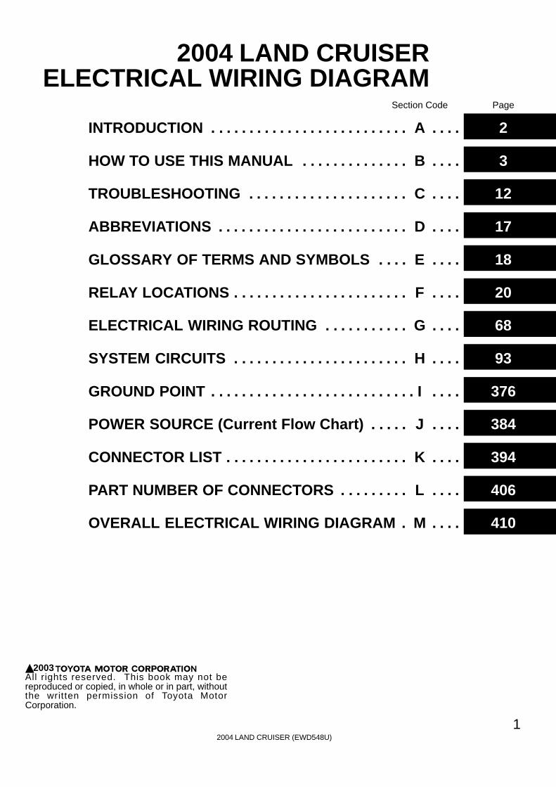
2004 LAND CRUISERELECTRICAL WIRING DIAGRAM
Section Code Page
INTRODUCTION A. . . . . . . . . . . . . . . . . . . . . . . . . . . . . . 2
HOW TO USE THIS MANUAL B. . . . . . . . . . . . . . . . . . 3
TROUBLESHOOTING C. . . . . . . . . . . . . . . . . . . . . . . . . 12
ABBREVIATIONS D. . . . . . . . . . . . . . . . . . . . . . . . . . . . . 17
GLOSSARY OF TERMS AND SYMBOLS E. . . . . . . . 18
RELAY LOCATIONS F. . . . . . . . . . . . . . . . . . . . . . . . . . . 20
ELECTRICAL WIRING ROUTING G. . . . . . . . . . . . . . . 68
SYSTEM CIRCUITS H. . . . . . . . . . . . . . . . . . . . . . . . . . . 93
GROUND POINT I. . . . . . . . . . . . . . . . . . . . . . . . . . . . . . . 376
POWER SOURCE (Current Flow Chart) J. . . . . . . . . 384
CONNECTOR LIST K. . . . . . . . . . . . . . . . . . . . . . . . . . . . 394
PART NUMBER OF CONNECTORS L. . . . . . . . . . . . . 406
OVERALL ELECTRICAL WIRING DIAGRAM M. . . . . 410

2004 LAND CRUISER (EWD548U)
2
A INTRODUCTION
This manual consists of the following 13 sections:
No. Section Description
AINDEX Index of the contents of this manual.
AINTRODUCTION Brief explanation of each section.
B HOW TO USE THISMANUAL Instructions on how to use this manual.
C TROUBLE-SHOOTING Describes the basic inspection procedures for electrical circuits.
D ABBREVIATIONS Defines the abbreviations used in this manual.
EGLOSSARY OFTERMS ANDSYMBOLS
Defines the symbols and functions of major parts.
F RELAY LOCATIONS Shows position of the Electronic Control Unit, Relays, Relay Block, etc.This section is closely related to the system circuit.
G ELECTRICALWIRING ROUTING
Describes position of Parts Connectors, Splice points, Ground points, etc.This section is closely related to the system circuit.
INDEX Index of the system circuits.
HSYSTEM CIRCUITS
Electrical circuits of each system are shown from the power supply through groundpoints. Wiring connections and their positions are shown and classified by codeaccording to the connection method. (Refer to the section, ”How to use this manual”).The ”System Outline” and ”Service Hints” useful for troubleshooting are also containedin this section.
I GROUND POINT Shows ground positions of all parts described in this manual.
J POWER SOURCE(Current Flow Chart) Describes power distribution from the power supply to various electrical loads.
K CONNECTOR LIST Describes the form of the connectors for the parts appeared in this book.This section is closely related to the system circuit.
L PART NUMBER OFCONNECTORS Indicates the part number of the connectors used in this manual.
MOVERALLELECTRICALWIRING DIAGRAM
Provides circuit diagrams showing the circuit connections.

2004 LAND CRUISER (EWD548U)
3
HOW TO USE THIS MANUAL B
This manual provides information on the electrical circuits installed on vehicles bydividing them into a circuit for each system.
The actual wiring of each system circuit is shown from the point where the powersource is received from the battery as far as each ground point. (All circuitdiagrams are shown with the switches in the OFF position.)
When troubleshooting any problem, first understand the operation of the circuitwhere the problem was detected (see System Circuit section), the power sourcesupplying power to that circuit (see Power Source section), and the ground points(see Ground Point section). See the System Outline to understand the circuitoperation.
When the circuit operation is understood, begin troubleshooting of the problemcircuit to isolate the cause. Use Relay Location and Electrical Wiring Routingsections to find each part, junction block and wiring harness connectors, wiringharness and wiring harness connectors, splice points, and ground points of eachsystem circuit. Internal wiring for each junction block is also provided for betterunderstanding of connection within a junction block.Wiring related to each system is indicated in each system circuit by arrows(from__, to__). When overall connections are required, see the Overall ElectricalWiring Diagram at the end of this manual.
[A]
[B]
[H]
[D]
[F]
[E]
[ I ]
[L]
[M]
[J]
[K]
[G][C]
1
2
IB
IB
3
4
47
2 1 11
13
4
1
2
6
3
1
2
B18
BL
R LG
R
B18G R
3
4
Rea
r C
ombi
natio
n Li
ght R
HR
7
Rea
r C
ombi
natio
n Li
ght L
HR
6
High MountedStop Light
H17
Light Failure Sensor
Stop Light SW
ABS ECU
S 6
CombinationMeter
C 7
BV11 W B
(Shielded)
BV11
I 5G W
IB2
IB1
IE114
BO
50
8L 4
15ASTOP
7.5AGAUGE
From Power Source System (See Page 66)
Stop Light
GR
WB
WB
WB
WB
GB
YG
RL
R
GR
WR
GW
WB
GW
W/G
)
( S/D
)L
L
( ( S/D
)
Sto
p
Sto
p
Rea
r Li
ghts
2004 LAND CRUISER (EWD548U)
4
B HOW TO USE THIS MANUAL
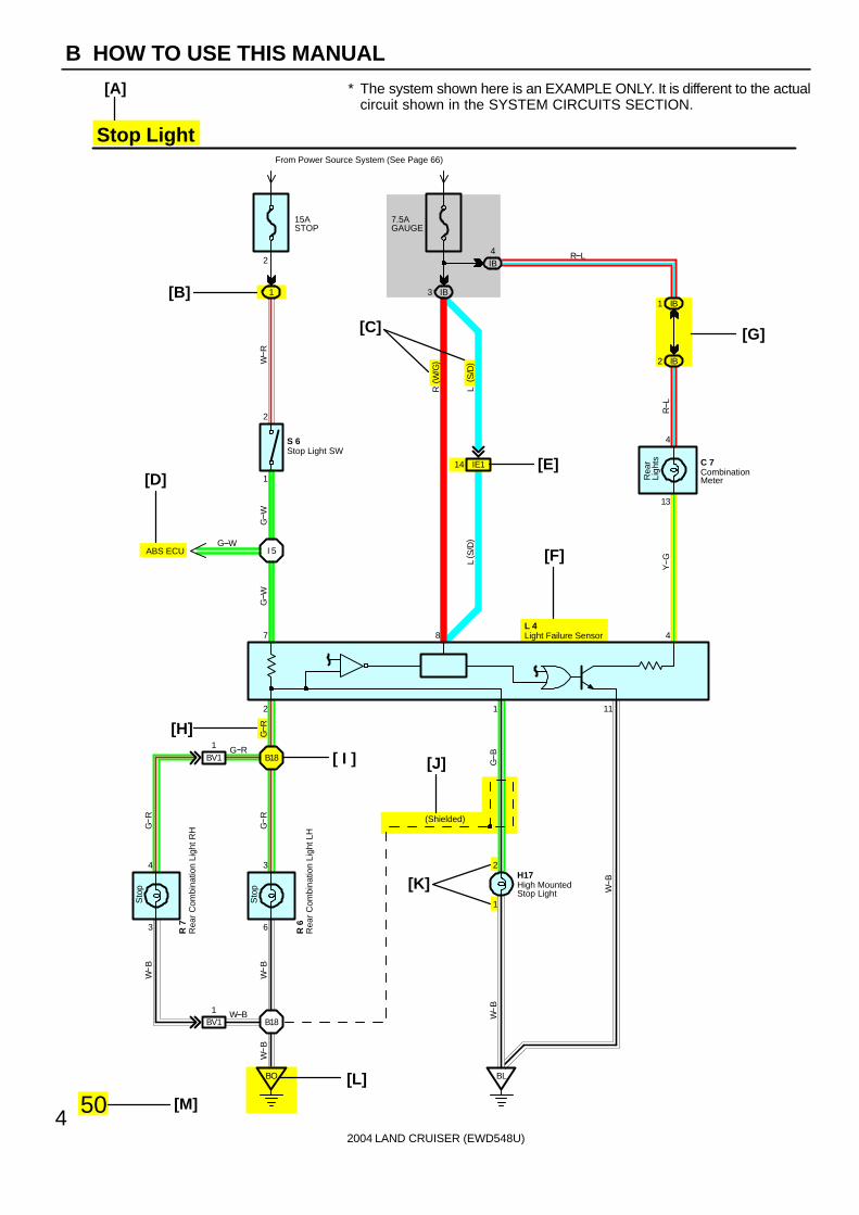
∗ The system shown here is an EXAMPLE ONLY. It is different to the actualcircuit shown in the SYSTEM CIRCUITS SECTION.
2004 LAND CRUISER (EWD548U)
5
B
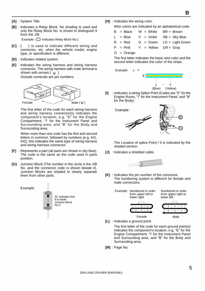
[A] : System Title
[B] : Indicates a Relay Block. No shading is used andonly the Relay Block No. is shown to distinguish itfrom the J/BExample: Indicates Relay Block No.1
[C] : ( ) is used to indicate different wiring andconnector, etc. when the vehicle model, enginetype, or specification is different.
[D] : Indicates related system.
[E] : Indicates the wiring harness and wiring harnessconnector. The wiring harness with male terminal isshown with arrows ( ).Outside numerals are pin numbers.
Female Male ( )
The first letter of the code for each wiring harnessand wiring harness connector(s) indicates thecomponent’s location, e.g, ”E” for the EngineCompartment, ”I” for the Instrument Panel andSurrounding area, and ”B” for the Body andSurrounding area.
When more than one code has the first and secondletters in common, followed by numbers (e.g, IH1,IH2), this indicates the same type of wiring harnessand wiring harness connector.
[F] : Represents a part (all parts are shown in sky blue).The code is the same as the code used in partsposition.
[G] : Junction Block (The number in the circle is the J/BNo. and the connector code is shown beside it).Junction Blocks are shaded to clearly separatethem from other parts.
3C indicates thatit is insideJunction BlockNo.3
Example:
[H] : Indicates the wiring color.
Wire colors are indicated by an alphabetical code.
B = Black W = White BR = Brown
L = Blue V = Violet SB = Sky Blue
R = Red G = Green LG = Light Green
P = Pink Y = Yellow GR = Gray
O = Orange
The first letter indicates the basic wire color and thesecond letter indicates the color of the stripe.
Example: L - Y
L(Blue)
Y(Yellow)
[I] : Indicates a wiring Splice Point (Codes are ”E” for theEngine Room, ”I” for the Instrument Panel, and ”B”for the Body).
The Location of splice Point I 5 is indicated by theshaded section.
[J] : Indicates a shielded cable.
[K] : Indicates the pin number of the connector.The numbering system is different for female andmale connectors.
Example: Numbered in orderfrom upper left tolower right
Numbered in orderfrom upper right tolower left
Female Male
[L] : Indicates a ground point.
The first letter of the code for each ground point(s)indicates the component’s location, e.g, ”E” for theEngine Compartment, ”I” for the Instrument Paneland Surrounding area, and ”B” for the Body andSurrounding area.
[M] : Page No.

[N]
[O]
[P]
[Q]
[R]
[S]
[T]
[U]
2004 LAND CRUISER (EWD548U)
6
B HOW TO USE THIS MANUAL
Current is applied at all times through the STOP fuse to TERMINAL 2 of the stop light SW.When the ignition SW is turned on, current flows from the GAUGE fuse to TERMINAL 8 of the light failure sensor, and also flowsthrough the rear lights warning light to TERMINAL 4 of the light failure sensor.
Stop Light Disconnection WarningWhen the ignition SW is turned on and the brake pedal is pressed (Stop light SW on), if the stop light circuit is open, the currentflowing from TERMINAL 7 of the light failure sensor to TERMINALS 1, 2 changes, so the light failure sensor detects thedisconnection and the warning circuit of the light failure sensor is activated.As a result, the current flows from TERMINAL 4 of the light failure sensor to TERMINAL 11 to GROUND and turns the rear lightswarning light on. By pressing the brake pedal, the current flowing to TERMINAL 8 of the light failure sensor keeps the warningcircuit on and holds the warning light on until the ignition SW is turned off.
S6 Stop Light SW2-1 : Closed with the brake pedal depressed
L4 Light Failure Sensor1, 2, 7-Ground : Approx. 12 volts with the stop light SW on
4, 8-Ground : Approx. 12 volts with the ignition SW at ON position11-Ground : Always continuity
: Parts Location
Code See Page Code See Page Code See Page
C7 34 L4 36 R7 37
H17 36 R6 37 S6 35
: Relay Blocks
Code See Page Relay Blocks (Relay Block Location)
1 18 R/B No.1 (Instrument Panel Brace LH)
: Junction Block and Wire Harness Connector
Code See Page Junction Block and Wire Harness (Connector Location)
IB 20 Instrument Panel Wire and Instrument Panel J/B (Lower Finish Panel)
3C 22 Instrument Panel Wire and J/B No.3 (Instrument Panel Brace LH)
: Connector Joining Wire Harness and Wire Harness
Code See Page Joining Wire Harness and Wire Harness (Connector Location)
IE1 42 Floor Wire and Instrument Panel Wire (Left Kick Panel)
BV1 50 Luggage Room Wire and Floor Wire (Luggage Room Left)
: Ground Points
Code See Page Ground Points Location
BL 50 Under the Left Center Pillar
BO 50 Back Panel Center
: Splice Points
Code See Page Wire Harness with Splice Points Code See Page Wire Harness with Splice Points
I5 44 Cowl Wire B18 50 Luggage Room Wire
System Outline
Service Hints
2004 LAND CRUISER (EWD548U)
7
B
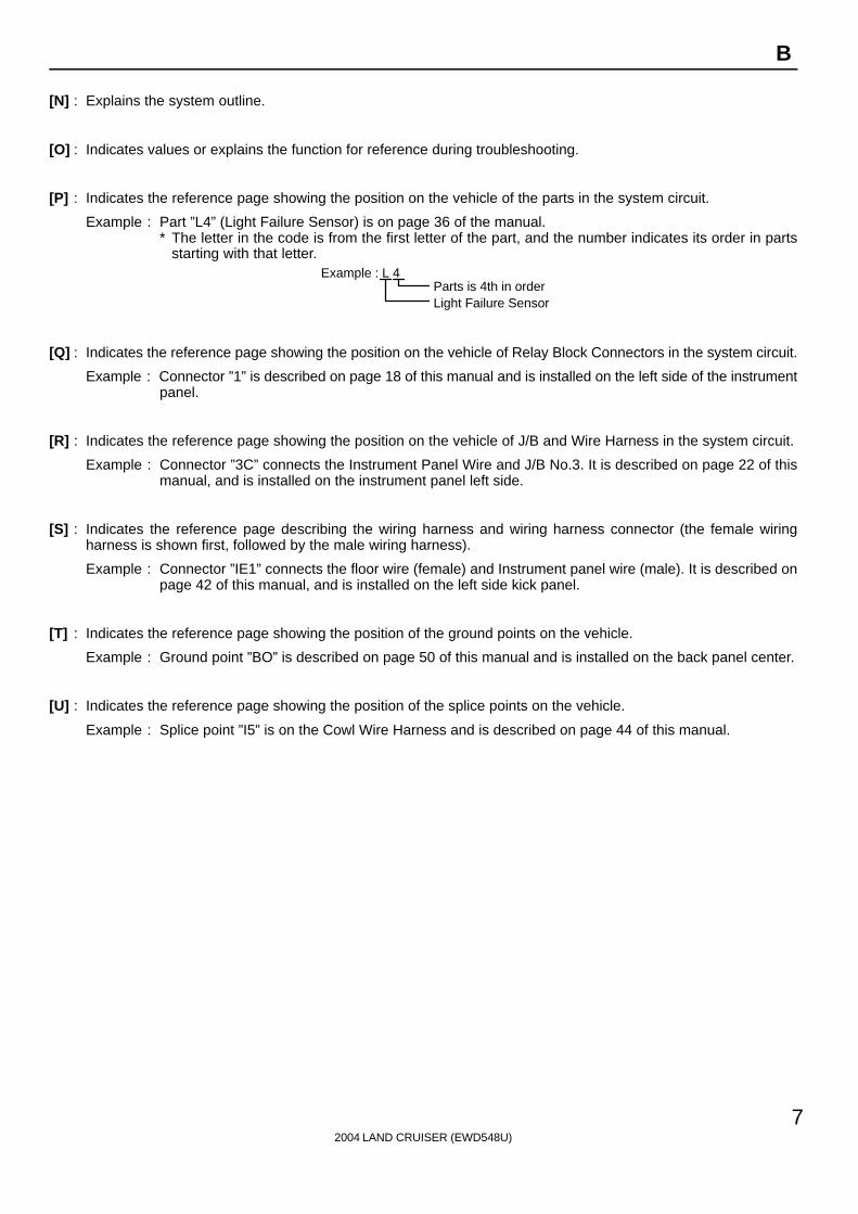
[N] : Explains the system outline.
[O] : Indicates values or explains the function for reference during troubleshooting.
[P] : Indicates the reference page showing the position on the vehicle of the parts in the system circuit.
Example : Part ”L4” (Light Failure Sensor) is on page 36 of the manual.∗ The letter in the code is from the first letter of the part, and the number indicates its order in parts
starting with that letter.Example : L 4 Á
ÁParts is 4th in orderLight Failure Sensor
[Q] : Indicates the reference page showing the position on the vehicle of Relay Block Connectors in the system circuit.
Example : Connector ”1” is described on page 18 of this manual and is installed on the left side of the instrumentpanel.
[R] : Indicates the reference page showing the position on the vehicle of J/B and Wire Harness in the system circuit.
Example : Connector ”3C” connects the Instrument Panel Wire and J/B No.3. It is described on page 22 of thismanual, and is installed on the instrument panel left side.
[S] : Indicates the reference page describing the wiring harness and wiring harness connector (the female wiringharness is shown first, followed by the male wiring harness).
Example : Connector ”IE1” connects the floor wire (female) and Instrument panel wire (male). It is described onpage 42 of this manual, and is installed on the left side kick panel.
[T] : Indicates the reference page showing the position of the ground points on the vehicle.
Example : Ground point ”BO” is described on page 50 of this manual and is installed on the back panel center.
[U] : Indicates the reference page showing the position of the splice points on the vehicle.
Example : Splice point ”I5” is on the Cowl Wire Harness and is described on page 44 of this manual.
2004 LAND CRUISER (EWD548U)
8
B HOW TO USE THIS MANUAL
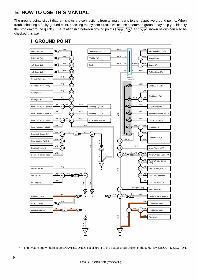
The ground points circuit diagram shows the connections from all major parts to the respective ground points. Whentroubleshooting a faulty ground point, checking the system circuits which use a common ground may help you identifythe problem ground quickly. The relationship between ground points ( EA , IB and IC shown below) can also bechecked this way.
5
5
5
5
4
4
4
4
4BA15
IB18
EA2
ID115
IC33
IA12
E 3
W-B
W-B
W-B
W-B
W-B
W-B
W-B
W-B
W-B W-B
W-B
W-B W-B
W-B
W-B W-B W-B
W-B
W-B
W-B
W-B
W-B
W-B
W-B
W-B W-B W-B
W-B
BR
W-B
BR BR
W-B
W-BW-B
W-B
W-B
W-B
W-BW-B W-B
W-B
W-B
W-B
W-B
W-B
BR
W-B
BRBR
BR
W-B (4A-GZE)
W-BW-B
I 2
I 2
B 5I 5
I 5
I 5
B 5
B 5
B 5
I 5
I 5
I 3I 3
E 3
E 3
E 3
E 2
E 4
E 5
E 4
E 5
E 6E 4
E 4
B 4
EA
I 4
B 4
B 4
I 4 I 8
IB IC
4
4
3E5
3E6
3G13
3F3
3D1
3B7
W-B
W-B
W-BW-B
W-B
W-B
W-B
W-B
W-B
W-B
W-B
W-B
W-B
W-B
W-B
I 6
I 6
I 23C7
10
A
A
A
A
A
A
JunctionConnector
J 1
W-B
W-B
W-B
W-B
BR
W-B
W-B
W-B
W-B
W-B
W-B
I GROUND POINT
FAN MAIN Relay
FAN MAIN Relay
A/C Relay No.2
A/C Relay No.3
Radiator Fan Motor
Headlight Cleaner Relay
Headlight LH
Headlight RH
Front Fog Light LH
Brake Fluid Level SW
Front Fog Light RHFront Turn Signal Light RH
Front Clearance Light RH
Front Turn Signal Light LH
Front Clearance Light LH
Door Lock Control SW
Door Courtesy SW RH
Door Lock Motor RH
Door Lock Control Relay
Blower Resistor
Idle-Up SW
A/C Amplifier
Radio and Player
HEATER Relay
Auto Antenna Motor
A/C Control Assembly
Blower Motor
Blower SW
Parking Brake SW
Combination Meter
Combination SW
Cruise Control ECU
Remote Control Mirror SW
Turn Signal Flasher
Defogger SW
Unlock Warning SW
Power Window Master SW
Power Window ControlRelay
Door Courtesy SW LH
Door Lock Control SW
Door Lock Motor LH
Fuel Control SW
Woofer Speaker Amplifier
Combination Meter
Combination Meter
Fuel Sender
Cigarette Lighter
O/D Main SW
Clock
Combination SW
∗ The system shown here is an EXAMPLE ONLY. It is different to the actual circuit shown in the SYSTEM CIRCUITS SECTION.

2004 LAND CRUISER (EWD548U)
9
B
The ”Current Flow Chart” section, describes which parts each power source (fuses, fusible links, and circuit breakers)transmits current to. In the Power Source circuit diagram, the conditions when battery power is supplied to each systemare explained. Since all System Circuit diagrams start from the power source, the power source system must be fullyunderstood.
AC
C
S 2
6
6 5
2
2
2
Battery 30A AM2
Starter
Short Pin
100A ALT
Fusible Link Block
60A ABS
10A ECU-B
7.5A DOME
15A EFI
10A HAZARD
20A RADIO NO.1
10A HORN
20A
10A
Fuse Page
214230112122
194187180166210
ABS
Cigarette LighterCombination Meter
Key Reminder and Seat Belt WarningLight Auto Turn OffTheft Deterrent and Door Lock Control
ABS and Traction ControlCruise ControlElectronically Controlled TransmissionMultiplex Communication System
STOP
System
DOMEHeadlightInterior Light
3 EA2 1 EA1
E 6
E 7
E 7
2
2
22
2
2
2
2
INJECTION Relay
STARTER Relay
B
B
B
B-O 1
1
2
2
3
4
3
4
W-B
W-B
B-W
B-W
E 7
E 7
B
B
W 1.25B FL MAIN
50A MAIN
7.5A AM2
15A HAZ-RADIO
2
2
2
2
2
W
W
EB1
EB1
7
6W-R
I 2 I 2
I 2
W W
W
W
W
1
1
1
1
40A DOOR LOCK CB
7.5A DOME
1 W-L
R
1
1
2
4 3
1
11
1
1 1
1
G
G
W-R
15A TAIL
20A DEFOGB-Y
8 4
3 2
Ignition SWI 8
B-Y1 1
P-L
Battery
15A RAD CIG
2
TAILRelay
Power Source
J POWER SOURCE (Current Flow Chart)
Engine Room R/B (See Page 20)
2
WW
BB
BB
B
W-R
WW
W
G-WA
M2
AM
1
IG2
IG1
W
W
The chart below shows the route by which current flows from the battery to each electrical source(Fusible Link, Circuit Breaker, Fuse, etc.) and other parts.
∗ The system shown here is an EXAMPLE ONLY. It is different to the actual circuit shown in the SYSTEM CIRCUITS SECTION.

Black
[D]
K CONNECTOR LIST
J4 K1 K2 L1
L2 L3 L4 M1 M2 M3
M4 N1 N2 O1 O2
Dark Gray
Gray
Dark GrayBlackGrayGray
A B BA A B C C C
D DD D
AA
AA
AAA A 1
1 2 1 2
1 12 1
2
1 2 36 7 8 9 101112
4 5
71 23 45 6 8
4321
1 2 3 2 3 48 9 105 6
17
1 2 1 1
[A]
[C]
[B]J3
1 2 1 2
6 7 8
1 2A
A
A
AA AA B BA A B C C C
D DD D
I14 I15 I16 J1 J2Dark Gray Gray Black
2004 LAND CRUISER (EWD548U)
10
B HOW TO USE THIS MANUAL
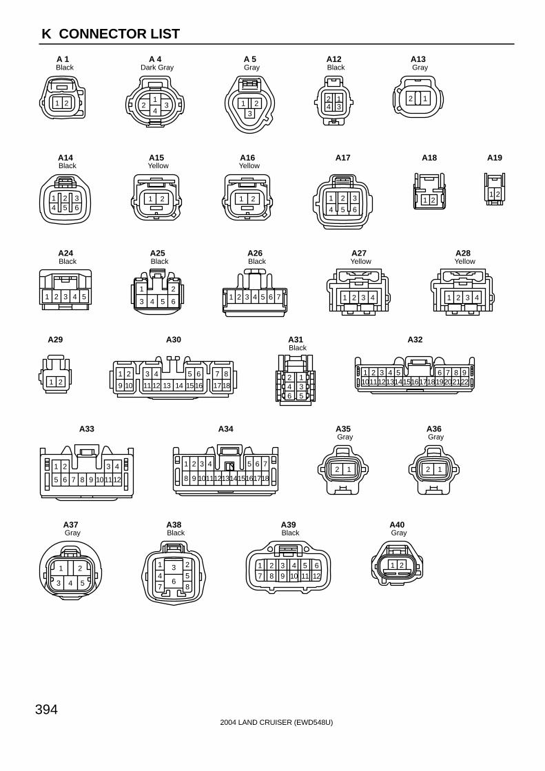
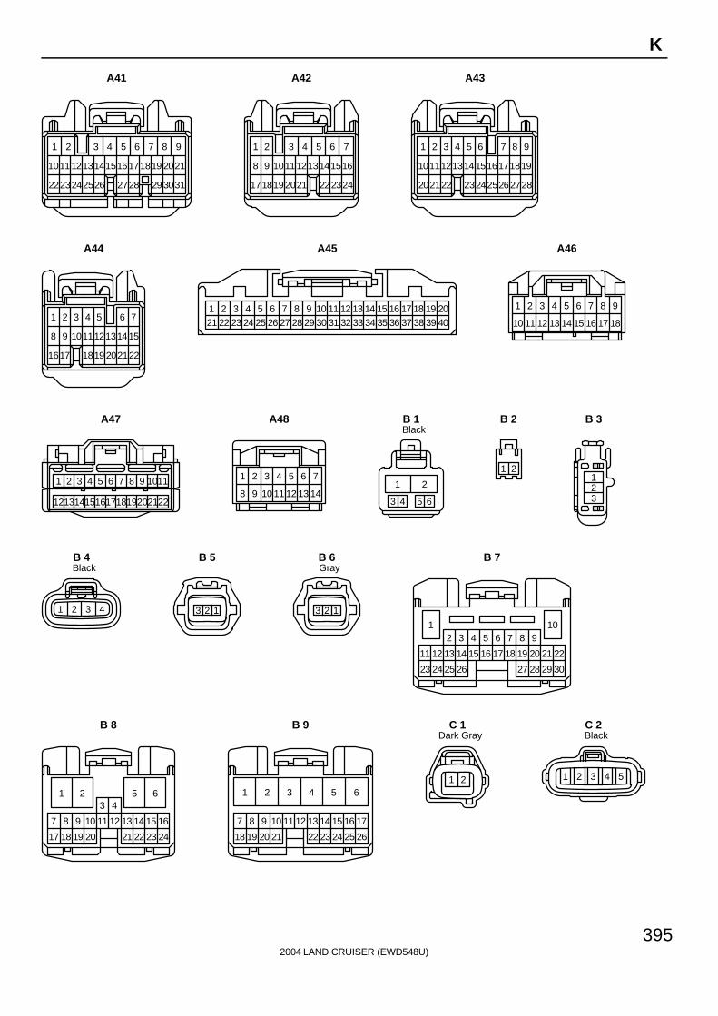
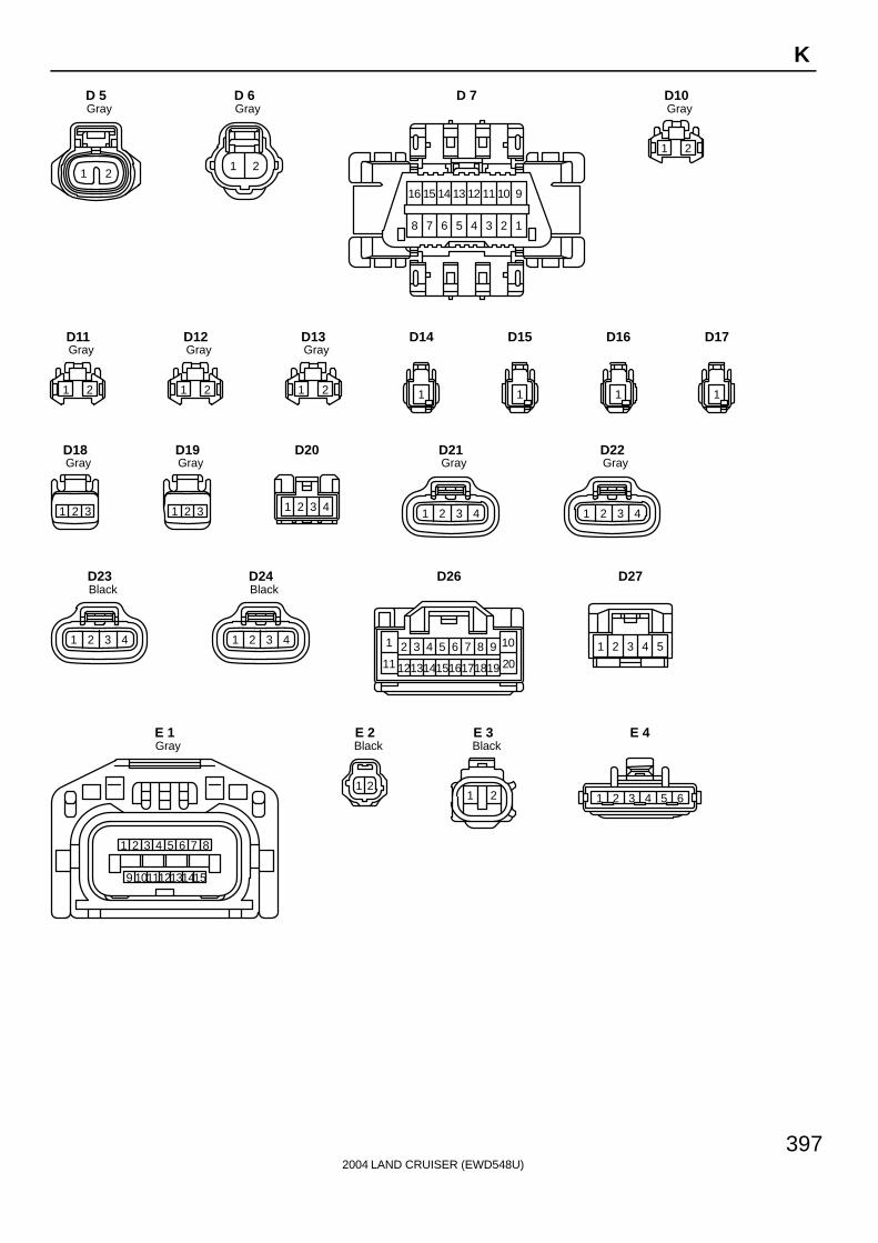
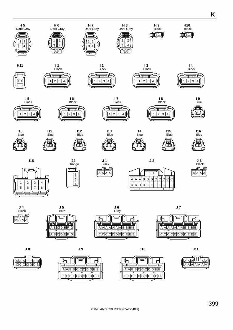
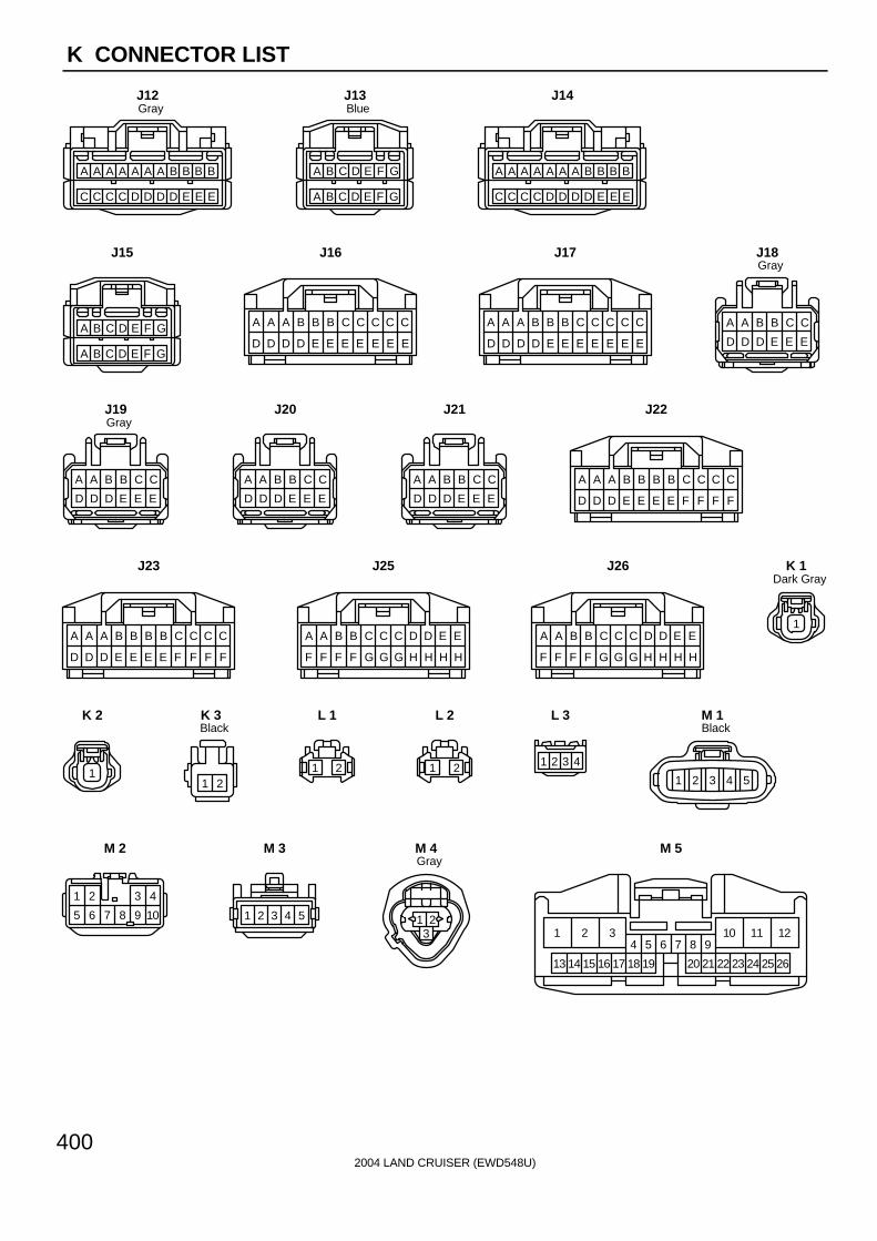
[A] : Indicates connector to be connected to a part. (The numeral indicates the pin No.)
[B] : Junction ConnectorIndicates a connector which is connected to a short terminal.
Junction Connector
Short TerminalSame Color
Junction connector in this manual include a short terminal which isconnected to a number of wire harnesses. Always performinspection with the short terminal installed. (When installing thewire harnesses, the harnesses can be connected to any positionwithin the short terminal grouping. Accordingly, in other vehicles,the same position in the short terminal may be connected to a wireharness from a different part.)Wire harness sharing the same short terminal grouping have thesame color.
[C] : Parts CodeThe first letter of the code is taken from the first letter of part, and the numbers indicates its order in parts whichstart with the same letter.
[D] : Connector ColorConnectors not indicated are milky white in color.
A 1
L PART NUMBER OF CONNECTORS
A/C Ambient Temp. Sensor
Code
90980-11070
Part Number
D 4 Diode (Courtesy)
Code
90980-11608
A 2 A/C Condenser Fan Motor 90980-11237 D 5 Diode (Interior Light) 90980-10962
A 3 A/C Condenser Fan Relay 90980-10940 D 6 Diode (Moon Roof) 90980-11608
A 4 A/C Condenser Fan Resistor 90980-10928
90980-11271
D 7 Door Lock Control Relay 90980-10848
A 5 A/C Magnetic Clutch
90980-11413
D 8 Door Lock Control SW LH90980-11148
A 6 A/T Oil Temp. Sensor
90980-11151
D 9 Door Lock Control SW RH
A 7 ABS Actuator
90980-11009
Door Courtesy SW LH90980-11097
A 8 ABS Actuator
90980-10941
Door Courtesy SW RH
A 9 ABS Speed Sensor Front LH
90980-11002
Door Courtesy SW Front LH
ABS Speed Sensor Front RH
90980-11856
Door Courtesy SW Front RH90980-11156
Airbag Sensor Front LH Door Courtesy SW Rear LH
Airbag Sensor Front RH Door Courtesy SW Rear RH
A10
A11
A12
A13 Airbag Squib 90980-11194 Door Key Lock and Unlock SW LH90980-11170
90980-11070
D10
D11
D12
D13
D14
D15
D16
D17 Door Key Lock and Unlock SW RH
Part NumberPart NamePart Name
[A] [B] [C]
2004 LAND CRUISER (EWD548U)
11
B
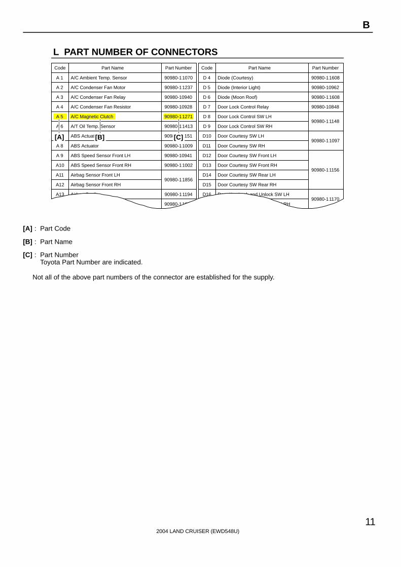
[A] : Part Code
[B] : Part Name
[C] : Part NumberToyota Part Number are indicated.
Not all of the above part numbers of the connector are established for the supply.

∗ The titles given inside the components are the names of the terminals (terminal codes) and are not treated as beingabbreviations.
2004 LAND CRUISER (EWD548U)
17
ABBREVIATIONS D
ABBREVIATIONS
The following abbreviations are used in this manual.
A/C = Air Conditioning
A/T = Automatic Transmission
ABS = Anti-Lock Brake System
ACIS = Acoustic Control Induction System
BA = Brake Assist
DIFF. = Differential
DVD = Digital Versatile Disc
EC = Electrochromic
ECU = Electronic Control Unit
ESA = Electronic Spark Advance
ETCS-i = Electronic Throttle Control System-intelligent
EVAP = Evaporative Emission
IC = Integrated Circuit
J/B = Junction Block
LH = Left-Hand
R/B = Relay Block
RH = Right-Hand
SFI = Sequential Multiport Fuel Injection
SRS = Supplemental Restraint System
SW = Switch
TEMP. = Temperature
TRAC = Traction Control
VSC = Vehicle Stability Control
VSV = Vacuum Switching Valve
w/ = With
w/o = Without
2004 LAND CRUISER (EWD548U)
394
K CONNECTOR LIST
1 2
BlackA 1
12 3
4
Dark GrayA 4
213
GrayA 5
2 14 3
BlackA12
12
GrayA13
1 2 34 5 6
BlackA14
1 2
YellowA15
1 2
YellowA16
1 2 3
654
A17
21
A18
21
A19
54321
BlackA24
1 2
3 4 5 6
BlackA25
1 2 3 4 5 6 7
BlackA26
1 2 3 4
YellowA27
1 2 3 4
YellowA28
1 2
A29
1 2 3 4 5 6 7 8
9 10 11 12 13 14 1516 1718
A30
123456
BlackA31
1 2 3 4 5 6 7 8 910111213141516171819202122
A32
1 2 3 4
5 6 7 8 9 101112
A33
1 2 3 4 5 6 7
8 9 101112131415161718
A34
12
GrayA35
12
GrayA36
1 2
3 4 5
GrayA37
2
5
86
31
4
7
BlackA38
1 2 3 4 5 67 8 9 11 1210
BlackA39
1 2
GrayA40
2004 LAND CRUISER (EWD548U)
395
K
211716151410
31272622
1311
2523
18
28
19
29
20
30
12
24
1 2 3 4 5 6 7 8 9
A41
1
16141312118
24222017
2
109
1918 21
15
23
3 4 5 6 7
A42
1 3 4 5 6 9
10 12131415 19
20 22 24 28
7
1617
252623
2
11
21
8
18
27
A43
1 2 3 4 5 7
8 9 101112 15
1617 19 22
6
1314
202118
A44
422
321 241
262362
277
288
3010
3111
3212
3313
3515
3616
3717
3818
2995
25 3414
3919
4020
A45
9
18
8
1716
76
1514
54
1312
32
11
1
10
A46
54 6 7 8
1918171516
321 9 1011
202122141312
A47
7
1413
65
1211
43
109
21
8
A48
3 4
1
65
2
BlackB 1
1 2
B 2
123
B 3
1 2 3 4
BlackB 4
2 13
B 5
2 13
GrayB 6
26 3023
1411
3 4
29
5 7 8 9
17 18 21
6
22
24
12
25
13
2
15 16 19 20
2827
1 10
B 7
18 2417
87 9 10
23
4
11 12 15
3
1613 14
19 20 2221
1 2 5 6
B 8
2322 2618
107
25
13 14 16 17
19
8
20
9 11 12 15
2421
1 2 3 4 5 6
B 9
1 2
Dark GrayC 1
1 2 3 4 5
BlackC 2

2004 LAND CRUISER (EWD548U)
396
K CONNECTOR LIST
1 2
Dark GrayC 3
1 2
5
3 4
6 7 8 9 10
C 5
1
2
GrayC10
1 2
GrayC11
16
65
15
1
14
43
1312 17
2
11
7
18
8
19
9
20
10
GrayC12
16
65
15
1
14
43
1312 17
2
11
7
18
8
19
9
20
10
C13
16
65
15
1
14
43
1312 17
2
11
7
18
8
19
9
20
10
GrayC14
16
65
15
1
14
43
1312 17
2
11
7
18
8
19
9
20
10
C15
1 2 4 7 8
9 10 1112131415 16 17
5 63
C16
9
1 2 3
16
4 5 86 7
10 11 151412 13
C17
7 8
1 2
12
4 5 6
9 1110
3
BlackC18
1 2 3 4 5 6 7 8 9
10 11 12 131415 16 17 18
BlackC19
171819161415 20
1 2 3 4
5 6 7 8 9 101112
13
A B
(w/ Side Airbag) YellowC25
1 2 3 4 5 6
7 8 9 101112
A
(*1) YellowC25
242523 26222021 2827
1 2 3 4 5 6
7 8 9 1011121314151617
1819
A B
YellowC26
171819161415 20
1 2 3 4
5 6 7 8 9 101112
13
A B
(w/ Side Airbag) YellowC27
1 2 3 4 5 6
7 8 9 101112
A
(*1) YellowC27
21
13 14
3
15
4
16
5
17
6
18
7
19
8
20
9
21
10
22
11
23
12
24
C28
1 2
YellowC29
1 2
YellowC30
1 2 3 4 5 6
7 8 9 10 11
12 13 14 15 16 17 21
20
18
2322
19
BlackD 1
1
4 5
2 3
6
BlackD 2
1 2
3 4
BlackD 3
1 2
GrayD 4
*1 : w/o Side Airbag
2004 LAND CRUISER (EWD548U)
397
K
1 2
GrayD 5
1 2
GrayD 6
16 15 14 13 12 11 10 9
8 7 6 5 4 3 2 1
D 7
1 2
GrayD10
1 2
GrayD11
1 2
GrayD12
1 2
GrayD13
1
D14
1
D15
1
D16
1
D17
1 2 3
GrayD18
1 2 3
GrayD19
1 2 3 4
D20
1 2 3 4
GrayD21
1 2 3 4
GrayD22
1 2 3 4
BlackD23
1 2 3 4
BlackD24
1 2 3 4 5 6 7 8 9 10
11 1213141516171819 20
D26
54321
D27
1 2 3 4 5 6 7 8
9 101112131415
GrayE 1
21
BlackE 2
1 2
BlackE 3
1 2 3 4 5 6
E 4

2004 LAND CRUISER (EWD548U)
398
K CONNECTOR LIST
1
17
29 3428
1918
98
20
10
21
33
11
76
13 14 15 16
22 23 26
12
432 5
2724 25
30 31 32
E 5
1
19
333231 3528
2320
118 12
34
13
76
15 16 17 18
24 25 26
14
432 5
27
29
21
9
30
22
10
E 6
1
17
29 3228
1918
98
20
10
21
31
11
76
13 14 15 16
22 23 26
12
432 5
27
30
24 25
E 7
16
3231 3528
2017
9 10
34
11
65
13 14 15
23 24 26
12
321 4
27
29
18
7
30
19
8
21 22 25
33
E 8
1
17
292827 3126
1918
98
20
10
21
30
11
76
13 14 15 16
22 23 24
12
432 5
25
E 9
1 2
BrownF 1
1 2
BrownF 2
1 2 3
GrayF 3
1 2 3
GrayF 4
1 2 3
4 5
BlackF 5
1
2
F 8
1
2
F 9
1 2
3 4
F10
1 2
F11
1 2 3
4 5
Dark GrayF12
1 2
Dark GrayF14
1 2
BlackF15
11
BlackF16
11
BlackF17
1
BlackF18
1
F19
21
3 4
BlackG 1
1
G 2
1 2
G 3
7
1413
65
1211
43
109
21
8
GrayG 4
1 2
BlackH 1
1 2
BrownH 2
1 2
BlackH 3
1 2
BrownH 4
2004 LAND CRUISER (EWD548U)
399
K
AAAAAA A A A A A A
CB C C D
HGGF G
BAA D E E
H H HFFF
CB C C D
HGGF G
BAA D E E
H H HFFF
AA A A B
DDDC D
AAA B B B
E E ECCC
A A A A
A A A A
1 2
3 4
Dark GrayH 5
21
3 4
Dark GrayH 6
1 2
3 4
Dark GrayH 7
21
3 4
Dark GrayH 8
1
BlackH 9
1
BlackH10
2 1
H11
1 2 3 4
BlackI 1
1 2 3 4
BlackI 2
1 2 3 4
BlackI 3
1 2 3 4
BlackI 4
1 2 3 4
BlackI 5
1 2 3 4
BlackI 6
1 2 3 4
BlackI 7
1 2 3 4
BlackI 8
1 2
BlueI 9
1 2
BlueI10
1 2
BlueI11
1 2
BlueI12
1 2
BlueI13
1 2
BlueI14
1 2
BlueI15
1 2
BlueI16
1 2 3 4
5 6 7 8
I18
1234
OrangeI22
A A A A
BlackJ 1
C
EE
CC
EE
CC
EE
BB
ED
BA
DD
A A
D
J 2 Black
J 3
BlackJ 4
CB D E F
FEDB C
G
G
A
A
BlueJ 5
AA A A B
DDDC D
AAA B B B
E E ECCC
GrayJ 6 J 7
BBAAAC C C D D D B
J 8 J 9 J10 J11
2004 LAND CRUISER (EWD548U)
400
K CONNECTOR LIST
E
HH
ED
HH
DC
GG
CC
GF
BB
FF
A A
F
E
HH
ED
HH
DC
GG
CC
GF
BB
FF
A A
F
C
FF
CC
FF
CB
EE
BB
EE
BA
DD
A A
D
C
FF
CC
FF
CB
EE
BB
EE
BA
DD
A A
D
A A B B C C
D D D E E E
A A B B C C
D D D E E E
A A B B C C
D D D E E E
C
EE
CC
EE
CC
EE
BB
ED
BA
DD
A A
D
C
EE
CC
EE
CC
EE
BB
ED
BA
DD
A A
DCB D E F
FEDB C
G
G
A
A
AA A A B
DDDC D
AAA B B B
E E ECCC
CB D E F
FEDB C
G
G
A
A
AA A A B
DDDC D
AAA B B B
E E ECCC
GrayJ12
BlueJ13 J14
J15 J16 J17
A A B B C C
D D D E E E
GrayJ18
GrayJ19 J20 J21 J22
J23 J25 J26
1
Dark GrayK 1
1
K 2
1 2
BlackK 3
1 2
L 1
1 2
L 2
1 2 3 4
L 3
54321
BlackM 1
1 2 3 4
5 6 7 8 9 10
M 2
1 2 3 4 5
M 3
1 23
GrayM 4
111032 121
15 161413 17
4 5 6 7 8 9
18 19 20 21 22 23 24 25 26
M 5

2004 LAND CRUISER (EWD548U)
401
K
21
15 16
4
18
5
19
6
20
7
21
8
22
9
23
10
24
11
25
13
27
14
28
3
17
12
26
M 6
1 2 3
4 5 6
M 7
1 2 3 4 5 6 7 8
9 10 11 12 13 14 15 16
M 9
1 2
GrayN 1
1 2 3 4 5 6 7 8 9
10 11 12 13 14 15 16 17 18
N 2
109876
54321
N 3
8765431 2
BlackN 4
1
BlackO 2
9
1 2 3
16
4 5 86 7
10 11 151412 13
O 5
1 2 3 4 5
6 7 8 9
GrayP 1
1 2
GrayP 2
1 2
GrayP 3
1
2
P 4
1 2
P 5
1 2
3 4 5 6
BlackP 6
1 2
3 4 5 6
BlackP 7
1
P 8
1 2
P 9
1 2
P10
1 2
P11
2
2013
10
19
3
14 1817
94 876
1615
1
11 12
5
P12
1 2 3
4 5
P14
1 2 3
4 5
P15
1 2 3
4 5
P16
1 2 3
4 5
P17
1 2 3 4 5 6
7 8 9 10 11 12
P18
1 2 3 4 5 6
7 8 9 10 11 12
P19
1 2 3 4 5 6
7 8 9 10 11 12
P20

2004 LAND CRUISER (EWD548U)
402
K CONNECTOR LIST
21
YellowP21
21
YellowP22
543216 7 8 9 101112
P23
543216 7 8 9 101112
P24
1 2
OrangeP25
1 2
P26
1 2
BlueP27
1 2
P28
1 2
P29
1 2
OrangeP30
1 2
BlueP31
1 2
P32
1 2
P33
1 2 3 4 5 6 7 8 9 10
BlackR 5
1 2 34 5 6 7 8
BlackR 6
21
BlackR 7
7 6 5 1
20191817 1514 10
234
11121316
89
2122
R 8
1
2 3 4 5
R 9
12
34
56
R10
1 32
R11
1 32
R12
12
34
56
R13
1
2
GrayR14
1 2
BlackR15
1 23 4
R16
1 23 4
R17
1
2
R19
1
2
R20
21
R21
1 2
R22
1 23 4
BlackR25
1 2
BlackR26
1
2
R27
1
R28
1
R29
23 41
R30
1 2
3 4 5 6
R31
2004 LAND CRUISER (EWD548U)
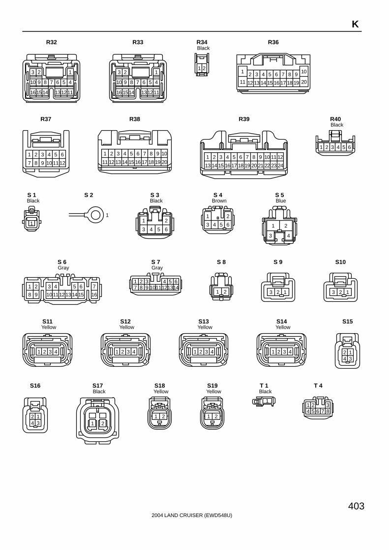
403
K
123
45678910
111213141516
R32
123
45678910
111213141516
R33
21
BlackR34
5 6 7 8 9 10
11 12 13 14
3 421
15 16 17 18 19 20
R36
7 8
1 2
12
4 5 6
9 1110
3
R37
1 2 3 4 5 6 7 8 9 10
11 12 13 14 15 16 17 18 19 20
R38
21
13 14
3
15
4
16
5
17
6
18
7
19
8
20
9
21
10
22
11
23
12
24
R39
1 2 3 4 5 6
BlackR40
1
BlackS 1
1
S 2
1 2
3 4 5 6
BlackS 3
1 2
3 4 5 6
BrownS 4
1
3
2
4
BlueS 5
21 3 4 5 6 7
8 9 101112131415 16
GrayS 6
643217 8 9 101112 14
513
GrayS 7
1 2
S 8
123
S 9
123
S10
1 2 3 4
YellowS11
1 2 3 4
YellowS12
1 2 3 4
YellowS13
1 2 3 4
YellowS14
124 3
S15
124 3
S16
21
BlackS17
1 2
YellowS18
1 2
YellowS19
1
BlackT 1
1 2 34 5 6 7 8
T 4

2004 LAND CRUISER (EWD548U)
404
K CONNECTOR LIST
422
321 241
262362
277
288
3010
3111
3212
3313
3515
3616
3717
3818
2995
25 3414
3919
4020
T 5
1 2 34 5 6 7 8
T 7
21 3 4 5 6 7
8 9 10 1112131415 16
T 8
1 2 34 5 6 7 8
BlackT 9
1 2 3 4 5 6 7
BlackT10
1 2 34 5 6 7 8
BlackT11
4 5
21
3
6 7
BlackT12
2 1
T13
2 1
T14
1 2 3
4 5 6 7 8 9
OrangeT15
1 2 3 4 5 6
BlackT16
1 2
BlackT17
1 2
3 4 5
T18
7
1413
65
1211
43
109
21
8
T19
2 14 36 5
T20
422
321 241
262362
277
288
3010
3111
3212
3313
3515
3616
3717
3818
2995
25 3414
3919
4020
T21
1 2 3 4
5 6 7 8 9 10
T22
35
1 2
T23
1 2
U 1
1 2 3
BlackV 1
1 2 3
BlackV 2
1 2
BlackV 3
1 2
BlackV 4
21
V 6
21
V 7

2004 LAND CRUISER (EWD548U)
405
K
1 2
BlackV 8
1 2
GrayV 9
1 2
BlueV10
1 2 3
GrayW 1
23 41
W 4
1 2 3 4
5 6 7 8
BlackY 1
1 2
Z 1

2004 LAND CRUISER (EWD548U)
76
G ELECTRICAL WIRING ROUTING
: Location of Connector Joining Wire Harness and Wire Harness: Location of Ground Points
: Location of Splice Points
2004 LAND CRUISER (EWD548U)
77
G
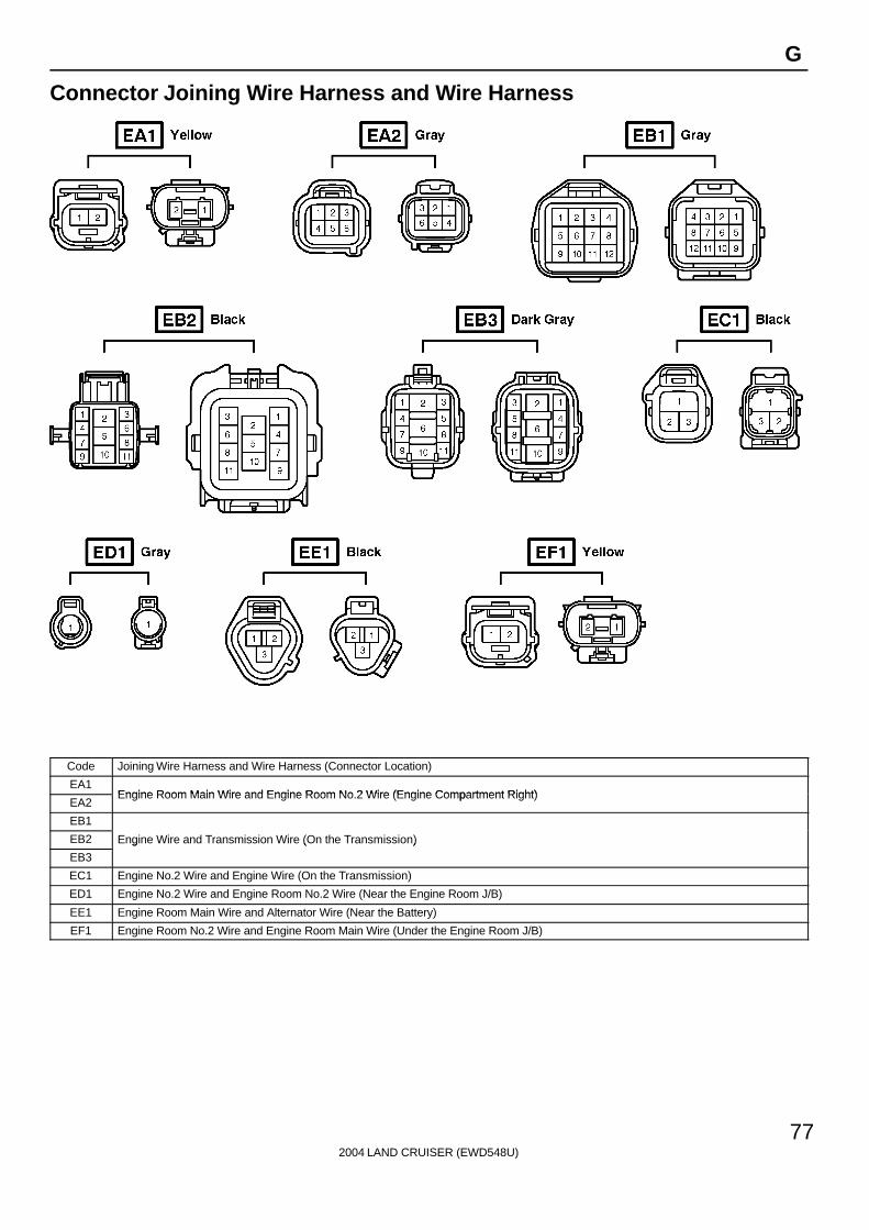
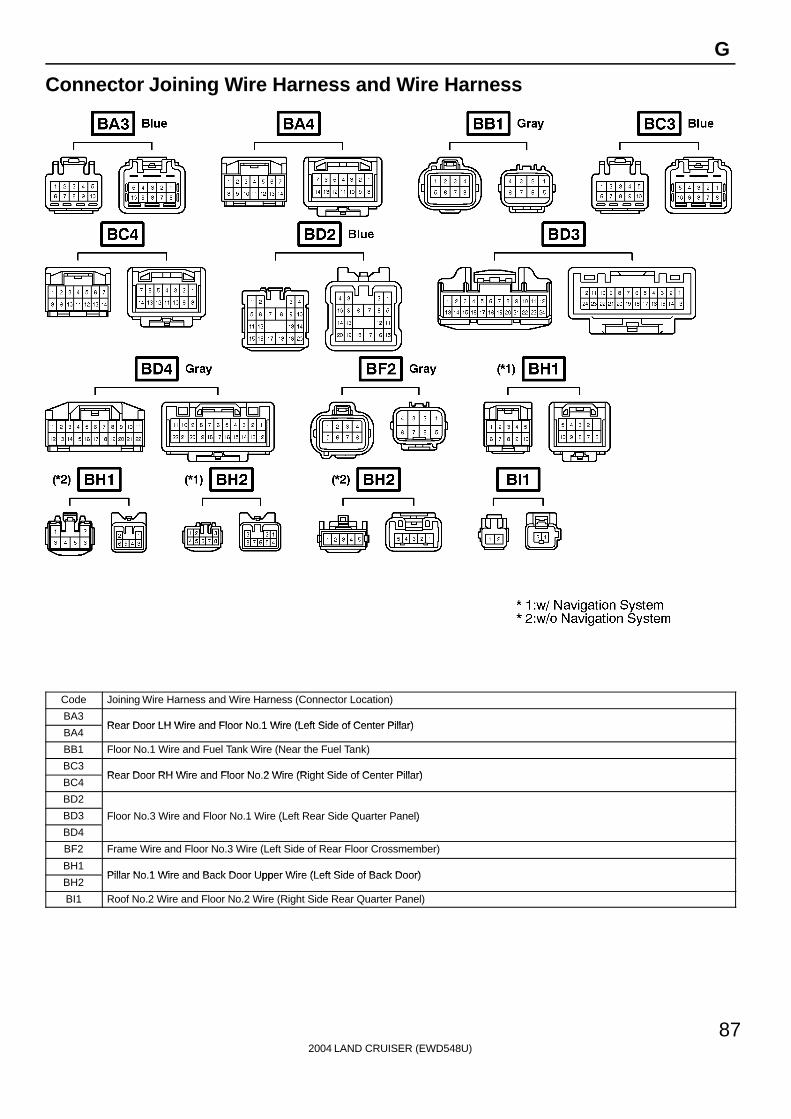
Connector Joining Wire Harness and Wire Harness
Code Joining Wire Harness and Wire Harness (Connector Location)
EA1Engine Room Main Wire and Engine Room No 2 Wire (Engine Compartment Right)
EA2Engine Room Main Wire and Engine Room No.2 Wire (Engine Compartment Right)
EB1
EB2 Engine Wire and Transmission Wire (On the Transmission)
EB3
g ( )
EC1 Engine No.2 Wire and Engine Wire (On the Transmission)
ED1 Engine No.2 Wire and Engine Room No.2 Wire (Near the Engine Room J/B)
EE1 Engine Room Main Wire and Alternator Wire (Near the Battery)
EF1 Engine Room No.2 Wire and Engine Room Main Wire (Under the Engine Room J/B)
2004 LAND CRUISER (EWD548U)
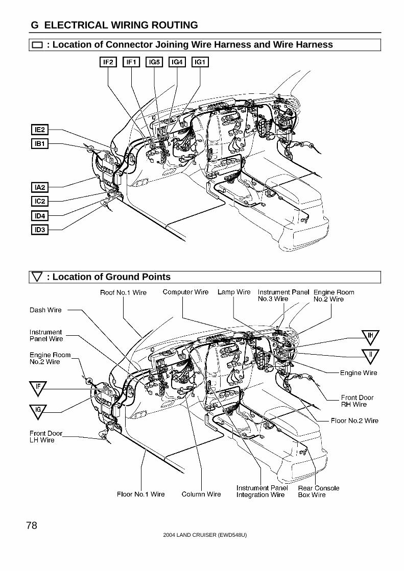
78
G ELECTRICAL WIRING ROUTING
: Location of Connector Joining Wire Harness and Wire Harness
: Location of Ground Points

2004 LAND CRUISER (EWD548U)
79
G
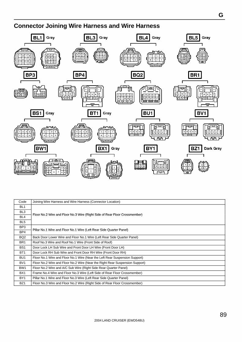
Connector Joining Wire Harness and Wire Harness
Code Joining Wire Harness and Wire Harness (Connector Location)
IA2 Engine Room No.2 Wire and Floor No.1 Wire (Left Kick Panel)
IB1 Engine Room No.2 Wire and Dash Wire (Left Kick Panel)
IC2 Front Door LH Wire and Dash Wire (Left Kick Panel)
ID3Dash Wire and Floor No 1 Wire (Left Kick Panel)
ID4Dash Wire and Floor No.1 Wire (Left Kick Panel)
IE2 Dash Wire and Roof No.1 Wire (Left Kick Panel)
IF1Instrument Panel Integration Wire and Instrument Panel Wire (Left Side of Instrument Panel)
IF2Instrument Panel Integration Wire and Instrument Panel Wire (Left Side of Instrument Panel)
IG1
IG4 Engine Room No.2 Wire and Dash Wire (Behind the Combination Meter)
IG5
g ( )

2004 LAND CRUISER (EWD548U)
80
G ELECTRICAL WIRING ROUTING
: Location of Connector Joining Wire Harness and Wire Harness
: Location of Splice Points

2004 LAND CRUISER (EWD548U)
81
G
Connector Joining Wire Harness and Wire Harness
Code Joining Wire Harness and Wire Harness (Connector Location)
IH2 Instrument Panel Integration Wire and Column Wire (Near the Ignition SW)
II3
II4 Dash Wire and Column Wire (Near the Ignition SW)
II5
( g )
IL3 Instrument Panel Integration Wire and Computer Wire (Instrument Panel Center)
IM2 Instrument Panel Integration Wire and Instrument Panel No.3 Wire (Right Side of Instrument Panel)
IN2 Engine Wire and Dash Wire (Behind the Glove Box)
IP2 Rear Console Box Wire and Dash Wire (Right Side of Rear Console)
IQ1 Instrument Panel Integration Wire and Lamp Wire (Behind the Glove Box)
IT1 Engine Room No.2 Wire and Dash Wire (Right Kick Panel)
2004 LAND CRUISER (EWD548U)
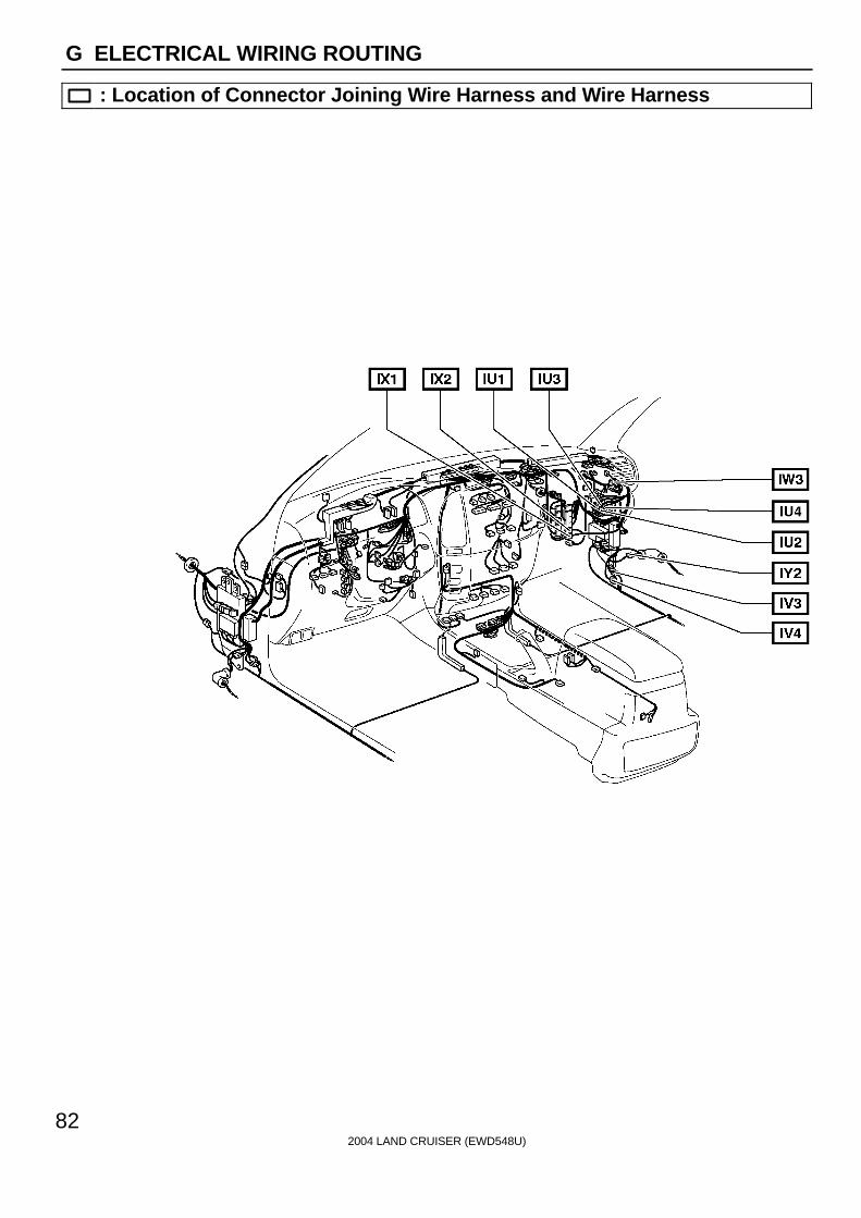
82
G ELECTRICAL WIRING ROUTING
: Location of Connector Joining Wire Harness and Wire Harness

2004 LAND CRUISER (EWD548U)
83
G
Connector Joining Wire Harness and Wire Harness
Code Joining Wire Harness and Wire Harness (Connector Location)
IU1
IU2Instrument Panel Integration Wire and Dash Wire (Behind the Glove Box)
IU3Instrument Panel Integration Wire and Dash Wire (Behind the Glove Box)
IU4
IV3Dash Wire and Floor No 2 Wire (Right Kick Panel)
IV4Dash Wire and Floor No.2 Wire (Right Kick Panel)
IW3 Engine Room No.2 Wire and Dash Wire (Behind the Glove Box)
IX1Instrument Panel Integration Wire and Engine Wire (Behind the Glove Box)
IX2Instrument Panel Integration Wire and Engine Wire (Behind the Glove Box)
IY2 Front Door RH Wire and Dash Wire (Right Kick Panel)

2004 LAND CRUISER (EWD548U)
84
G ELECTRICAL WIRING ROUTING
: Location of Connector Joining Wire Harness and Wire Harness

2004 LAND CRUISER (EWD548U)
85
G
Connector Joining Wire Harness and Wire Harness
Code Joining Wire Harness and Wire Harness (Connector Location)
Ia1 Dash Wire and Dash Wire (Behind the Combination Meter)
Ib1
Ib2 Dash Wire and Dash Wire (Behind the Combination Meter)
Ib3
( )
Ic2 Dash Wire and Dash Wire (Behind the Center Panel)
Id1
Id2Dash Wire and Dash Wire (Instrument Panel Center)
Id3Dash Wire and Dash Wire (Instrument Panel Center)
Id4
Ie1 Dash Wire and Dash Wire (Behind the Glove Box)
If1 Engine Wire and Engine Wire (Behind the Glove Box)
Ig1 Dash Wire and Floor No.2 Wire (Right Side of Front Console)
Ih1 Dash Wire and Dash Wire (Center Side of Front Console)

2004 LAND CRUISER (EWD548U)
86
G ELECTRICAL WIRING ROUTING
: Location of Connector Joining Wire Harness and Wire Harness
: Location of Ground Points
2004 LAND CRUISER (EWD548U)
87
G
Connector Joining Wire Harness and Wire Harness
Code Joining Wire Harness and Wire Harness (Connector Location)
BA3Rear Door LH Wire and Floor No 1 Wire (Left Side of Center Pillar)
BA4Rear Door LH Wire and Floor No.1 Wire (Left Side of Center Pillar)
BB1 Floor No.1 Wire and Fuel Tank Wire (Near the Fuel Tank)
BC3Rear Door RH Wire and Floor No 2 Wire (Right Side of Center Pillar)
BC4Rear Door RH Wire and Floor No.2 Wire (Right Side of Center Pillar)
BD2
BD3 Floor No.3 Wire and Floor No.1 Wire (Left Rear Side Quarter Panel)
BD4
( Q )
BF2 Frame Wire and Floor No.3 Wire (Left Side of Rear Floor Crossmember)
BH1Pillar No 1 Wire and Back Door Upper Wire (Left Side of Back Door)
BH2Pillar No.1 Wire and Back Door Upper Wire (Left Side of Back Door)
BI1 Roof No.2 Wire and Floor No.2 Wire (Right Side Rear Quarter Panel)

2004 LAND CRUISER (EWD548U)
88
G ELECTRICAL WIRING ROUTING
: Location of Connector Joining Wire Harness and Wire Harness
: Location of Splice Points
2004 LAND CRUISER (EWD548U)
89
G
Connector Joining Wire Harness and Wire Harness
Code Joining Wire Harness and Wire Harness (Connector Location)
BL1
BL3Floor No 2 Wire and Floor No 3 Wire (Right Side of Rear Floor Crossmember)
BL4Floor No.2 Wire and Floor No.3 Wire (Right Side of Rear Floor Crossmember)
BL5
BP3Pillar No 1 Wire and Floor No 1 Wire (Left Rear Side Quarter Panel)
BP4Pillar No.1 Wire and Floor No.1 Wire (Left Rear Side Quarter Panel)
BQ2 Back Door Lower Wire and Floor No.1 Wire (Left Rear Side Quarter Panel)
BR1 Roof No.3 Wire and Roof No.1 Wire (Front Side of Roof)
BS1 Door Lock LH Sub Wire and Front Door LH Wire (Front Door LH)
BT1 Door Lock RH Sub Wire and Front Door RH Wire (Front Door RH)
BU1 Floor No.1 Wire and Floor No.1 Wire (Near the Left Rear Suspension Support)
BV1 Floor No.2 Wire and Floor No.2 Wire (Near the Right Rear Suspension Support)
BW1 Floor No.2 Wire and A/C Sub Wire (Right Side Rear Quarter Panel)
BX1 Frame No.4 Wire and Floor No.3 Wire (Left Side of Rear Floor Crossmember)
BY1 Pillar No.1 Wire and Floor No.3 Wire (Left Rear Side Quarter Panel)
BZ1 Floor No.3 Wire and Floor No.2 Wire (Right Side of Rear Floor Crossmember)

2004 LAND CRUISER (EWD548U)
90
G ELECTRICAL WIRING ROUTING
: Location of Connector Joining Wire Harness and Wire Harness
: Location of Splice Points

2004 LAND CRUISER (EWD548U)
91
G
Connector Joining Wire Harness and Wire Harness
1 2 3
4 5
123
45
124567810
39
1 2
5
3 4
6 7 8 9 10 1 2 2 1
1 2 3
4 5
123
45
124567810
39
1 2
5
3 4
6 7 8 9 10
BM2 Gray
BO2 Gray
BM3 BN1
BO3
Code Joining Wire Harness and Wire Harness (Connector Location)
BM2Floor No 1 Wire and Front Seat LH Wire (Front Side Under the Driver’s Seat)
BM3Floor No.1 Wire and Front Seat LH Wire (Front Side Under the Driver’s Seat)
BN1 Seat No.2 Wire and Front Seat LH Wire (Rear Side Under the Driver’s Seat)
BO2Floor No 2 Wire and Front Seat RH Wire (Front Side Under the Front Passenger’s Seat)
BO3Floor No.2 Wire and Front Seat RH Wire (Front Side Under the Front Passenger’s Seat)

2004 LAND CRUISER (EWD548U)
92
HINT
WIRE COLOR AND TERMINAL NUMBER
In some parts of the instrumental panel wiring harness, thesame wire color (i.e. SB: Sky Blue) is used for all the wiringto a specific connector.In order to identify the wiring, the terminal number is printedon the wiring.Install the wiring to the connector position with the sameterminal number.Some early production Vehicles may not have these terminalnumbers printed.
2004 LAND CRUISER (EWD548U)
68
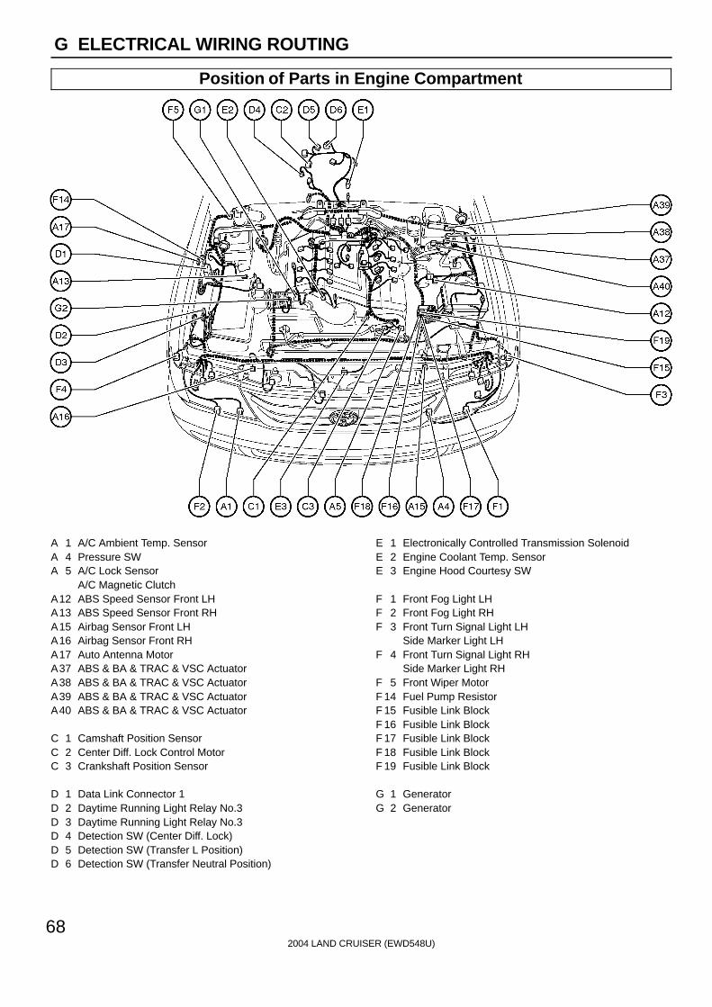
G ELECTRICAL WIRING ROUTING
Position of Parts in Engine Compartment
A 1 A/C Ambient Temp. SensorA 4 Pressure SWA 5 A/C Lock Sensor
A/C Magnetic ClutchA12 ABS Speed Sensor Front LHA13 ABS Speed Sensor Front RHA15 Airbag Sensor Front LHA16 Airbag Sensor Front RHA17 Auto Antenna MotorA37 ABS & BA & TRAC & VSC ActuatorA38 ABS & BA & TRAC & VSC ActuatorA39 ABS & BA & TRAC & VSC ActuatorA40 ABS & BA & TRAC & VSC Actuator
C 1 Camshaft Position SensorC 2 Center Diff. Lock Control MotorC 3 Crankshaft Position Sensor
D 1 Data Link Connector 1D 2 Daytime Running Light Relay No.3D 3 Daytime Running Light Relay No.3D 4 Detection SW (Center Diff. Lock)D 5 Detection SW (Transfer L Position)D 6 Detection SW (Transfer Neutral Position)
E 1 Electronically Controlled Transmission SolenoidE 2 Engine Coolant Temp. SensorE 3 Engine Hood Courtesy SW
F 1 Front Fog Light LHF 2 Front Fog Light RHF 3 Front Turn Signal Light LH
Side Marker Light LHF 4 Front Turn Signal Light RH
Side Marker Light RHF 5 Front Wiper MotorF 14 Fuel Pump ResistorF 15 Fusible Link BlockF 16 Fusible Link BlockF 17 Fusible Link BlockF 18 Fusible Link BlockF 19 Fusible Link Block
G 1 GeneratorG 2 Generator
2004 LAND CRUISER (EWD548U)
69
G
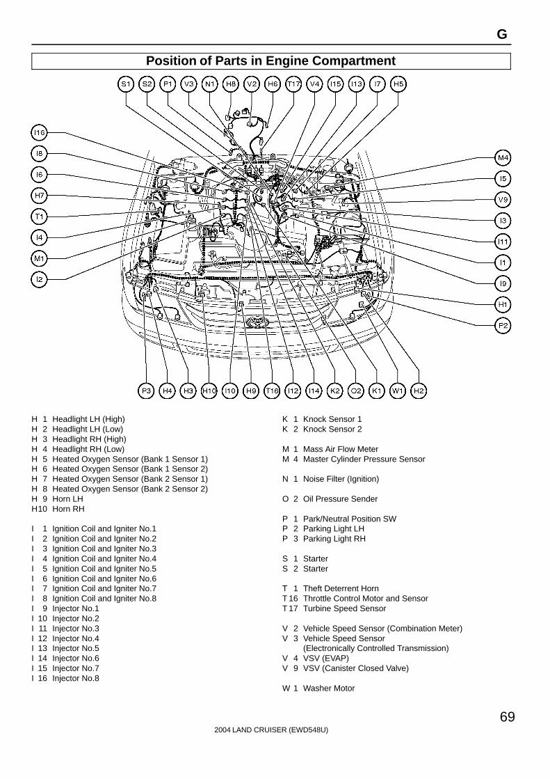
Position of Parts in Engine Compartment
H 1 Headlight LH (High)H 2 Headlight LH (Low)H 3 Headlight RH (High)H 4 Headlight RH (Low)H 5 Heated Oxygen Sensor (Bank 1 Sensor 1)H 6 Heated Oxygen Sensor (Bank 1 Sensor 2)H 7 Heated Oxygen Sensor (Bank 2 Sensor 1)H 8 Heated Oxygen Sensor (Bank 2 Sensor 2)H 9 Horn LHH10 Horn RH
I 1 Ignition Coil and Igniter No.1I 2 Ignition Coil and Igniter No.2I 3 Ignition Coil and Igniter No.3I 4 Ignition Coil and Igniter No.4I 5 Ignition Coil and Igniter No.5I 6 Ignition Coil and Igniter No.6I 7 Ignition Coil and Igniter No.7I 8 Ignition Coil and Igniter No.8I 9 Injector No.1I 10 Injector No.2I 11 Injector No.3I 12 Injector No.4I 13 Injector No.5I 14 Injector No.6I 15 Injector No.7I 16 Injector No.8
K 1 Knock Sensor 1K 2 Knock Sensor 2
M 1 Mass Air Flow MeterM 4 Master Cylinder Pressure Sensor
N 1 Noise Filter (Ignition)
O 2 Oil Pressure Sender
P 1 Park/Neutral Position SWP 2 Parking Light LHP 3 Parking Light RH
S 1 StarterS 2 Starter
T 1 Theft Deterrent HornT 16 Throttle Control Motor and SensorT 17 Turbine Speed Sensor
V 2 Vehicle Speed Sensor (Combination Meter)V 3 Vehicle Speed Sensor
(Electronically Controlled Transmission)V 4 VSV (EVAP)V 9 VSV (Canister Closed Valve)
W 1 Washer Motor
2004 LAND CRUISER (EWD548U)
70
G ELECTRICAL WIRING ROUTING
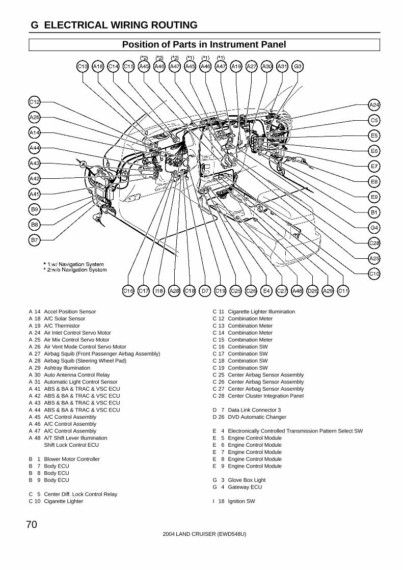
Position of Parts in Instrument Panel
A 14 Accel Position SensorA 18 A/C Solar SensorA 19 A/C ThermistorA 24 Air Inlet Control Servo MotorA 25 Air Mix Control Servo MotorA 26 Air Vent Mode Control Servo MotorA 27 Airbag Squib (Front Passenger Airbag Assembly)A 28 Airbag Squib (Steering Wheel Pad)A 29 Ashtray IlluminationA 30 Auto Antenna Control RelayA 31 Automatic Light Control SensorA 41 ABS & BA & TRAC & VSC ECUA 42 ABS & BA & TRAC & VSC ECUA 43 ABS & BA & TRAC & VSC ECUA 44 ABS & BA & TRAC & VSC ECUA 45 A/C Control AssemblyA 46 A/C Control AssemblyA 47 A/C Control AssemblyA 48 A/T Shift Lever Illumination
Shift Lock Control ECU
B 1 Blower Motor ControllerB 7 Body ECUB 8 Body ECUB 9 Body ECU
C 5 Center Diff. Lock Control RelayC 10 Cigarette Lighter
C 11 Cigarette Lighter IlluminationC 12 Combination MeterC 13 Combination MeterC 14 Combination MeterC 15 Combination MeterC 16 Combination SWC 17 Combination SWC 18 Combination SWC 19 Combination SWC 25 Center Airbag Sensor AssemblyC 26 Center Airbag Sensor AssemblyC 27 Center Airbag Sensor AssemblyC 28 Center Cluster Integration Panel
D 7 Data Link Connector 3D 26 DVD Automatic Changer
E 4 Electronically Controlled Transmission Pattern Select SWE 5 Engine Control ModuleE 6 Engine Control ModuleE 7 Engine Control ModuleE 8 Engine Control ModuleE 9 Engine Control Module
G 3 Glove Box LightG 4 Gateway ECU
I 18 Ignition SW
2004 LAND CRUISER (EWD548U)
71
G
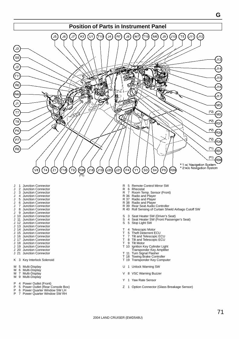
Position of Parts in Instrument Panel
J 1 Junction ConnectorJ 2 Junction ConnectorJ 3 Junction ConnectorJ 4 Junction ConnectorJ 5 Junction ConnectorJ 6 Junction ConnectorJ 7 Junction ConnectorJ 8 Junction ConnectorJ 9 Junction ConnectorJ 10 Junction ConnectorJ 11 Junction ConnectorJ 12 Junction ConnectorJ 13 Junction ConnectorJ 14 Junction ConnectorJ 15 Junction ConnectorJ 16 Junction ConnectorJ 17 Junction ConnectorJ 18 Junction ConnectorJ 19 Junction ConnectorJ 20 Junction ConnectorJ 21 Junction Connector
K 3 Key Interlock Solenoid
M 5 Multi-DisplayM 6 Multi-DisplayM 7 Multi-DisplayM 9 Multi-Display
P 4 Power Outlet (Front)P 5 Power Outlet (Rear Console Box)P 6 Power Quarter Window SW LHP 7 Power Quarter Window SW RH
R 5 Remote Control Mirror SWR 6 RheostatR 7 Room Temp. Sensor (Front)R 36 Radio and PlayerR 37 Radio and PlayerR 38 Radio and PlayerR 39 Rear Seat Audio ControllerR 40 Roll Sensing of Curtain Shield Airbags Cutoff SW
S 3 Seat Heater SW (Driver’s Seat)S 4 Seat Heater SW (Front Passenger’s Seat)S 5 Stop Light SW
T 4 Telescopic MotorT 5 Theft Deterrent ECUT 7 Tilt and Telescopic ECUT 8 Tilt and Telescopic ECUT 9 Tilt MotorT 10 Ignition Key Cylinder Light
Transponder Key AmplifierT 11 Turn Signal FlasherT 18 Towing Brake ControllerT 19 Transponder Key Computer
U 1 Unlock Warning SW
V 8 VSC Warning Buzzer
Y 1 Yaw Rate Sensor
Z 1 Option Connector (Glass Breakage Sensor)

2004 LAND CRUISER (EWD548U)
72
G ELECTRICAL WIRING ROUTING
Position of Parts in Body
A32 A/C Amplifier (Rear)A33 A/C Amplifier (Rear)A34 A/C Amplifier (Rear)A35 ABS Speed Sensor Rear LHA36 ABS Speed Sensor Rear RH
B 2 Back Door Courtesy SWB 3 Back Door Key Lock and Unlock SWB 4 Back Door Lock Motor
Back Door Unlock Detection SW
C29 Curtain Shield Airbag Squib LHC30 Curtain Shield Airbag Squib RH
D10 Door Courtesy Light Front LHD11 Door Courtesy Light Front RHD12 Door Courtesy Light Rear LHD13 Door Courtesy Light Rear RHD14 Door Courtesy SW Front LHD15 Door Courtesy SW Front RHD16 Door Courtesy SW Rear LHD17 Door Courtesy SW Rear RHD18 Door Key Lock and Unlock SW LHD19 Door Key Lock and Unlock SW RHD20 Door Lock Control SW RHD21 Door Lock Motor Front LH
Door Unlock Detection SW Front LHD22 Door Lock Motor Front RH
Door Unlock Detection SW Front RHD23 Door Lock Motor Rear LH
Door Unlock Detection SW Rear LHD24 Door Lock Motor Rear RH
Door Unlock Detection SW Rear RHD27 Door Control Receiver
F 8 Front Door Speaker LHF 9 Front Door Speaker RHF 10 Front Interior Light
Rear Personal LightF 11 Front Personal LightF 12 Fuel Pump
Fuel Sender
H11 High Mounted Stop Light
I 22 Inner Mirror
J 22 Junction ConnectorJ 23 Junction ConnectorJ 25 Junction ConnectorJ 26 Junction Connector
L 1 License Plate Light LHL 2 License Plate Light RH
M 2 Moon Roof Control ECUM 3 Moon Roof Control SW
N 2 Navigation ECUN 3 Navigation ECUN 4 Navigation ECU
O 5 Overhead J/B

2004 LAND CRUISER (EWD548U)
73
G
Position of Parts in Body
P 8 Parking Brake SWP 9 Power Outlet (Luggage Compartment)P10 Power Vent Window Motor LHP 11 Power Vent Window Motor RHP12 Power Window Master SWP14 Power Window Motor Front LHP15 Power Window Motor Front RHP16 Power Window Motor Rear LHP17 Power Window Motor Rear RHP18 Power Window Control SW Front RHP19 Power Window Control SW Rear LHP20 Power Window Control SW Rear RHP21 Pretensioner LHP22 Pretensioner RH
R 8 Rear A/C Control SWR 9 Rear Air Mix Control Servo MotorR10 Rear Combination Light LHR11 Rear Combination Light LHR12 Rear Combination Light RHR13 Rear Combination Light RHR14 Rear Cooler Blower MotorR15 Rear Cooler Magnetic ValveR16 Rear Cooler Power TransistorR17 Rear Cooler RelayR19 Rear Door Speaker LHR20 Rear Door Speaker RHR21 Rear Evaporator Temp. SensorR22 Rear Heater Blower MotorR25 Rear Heater Power TransistorR26 Rear Inlet Air Temp. Sensor
R27 Rear Interior LightR28 Rear Window DefoggerR29 Rear Window DefoggerR30 Rear Wiper MotorR31 Rear Wiper RelayR32 Remote Control Mirror LHR33 Remote Control Mirror RHR34 Room Temp. Sensor (Rear)
S 6 Stereo Component AmplifierS 7 Stereo Component AmplifierS 11 Side Airbag Sensor Front LHS12 Side Airbag Sensor Front RHS13 Side Airbag Sensor Rear LHS14 Side Airbag Sensor Rear RH
T 12 Trailer SocketT 13 Tweeter LHT 14 Tweeter RHT 15 Towing Converter RelayT 20 Television CameraT 21 Television Camera ECUT 22 Television Camera ECUT 23 Towing Hitch Relay
V 1 Vapor Pressure SensorV 6 Vanity Light LHV 7 Vanity Light RHV10 VSV (Pressure Switching Valve)
W 4 Woofer (Speaker)

2004 LAND CRUISER (EWD548U)
74
G ELECTRICAL WIRING ROUTING
Position of Parts in Seat
B 5 Buckle SW LHB 6 Buckle SW RH
L 3 Lumbar Support Control SW (Driver’s Seat)
P23 Power Seat Control SW (Driver’s Seat)P24 Power Seat Control SW (Front Passenger’s Seat)P25 Power Seat Motor (Driver’s Seat Front Vertical Control)P26 Power Seat Motor
(Driver’s Seat Lumbar Support Control)P27 Power Seat Motor (Driver’s Seat Rear Vertical Control)P28 Power Seat Motor (Driver’s Seat Reclining Control)P29 Power Seat Motor (Driver’s Seat Slide Control)P30 Power Seat Motor
(Front Passenger’s Seat Front Vertical Control)P31 Power Seat Motor
(Front Passenger’s Seat Rear Vertical Control)P32 Power Seat Motor
(Front Passenger’s Seat Reclining Control)P33 Power Seat Motor
(Front Passenger’s Seat Slide Control)
S 8 Seat Belt Warning Occupant Detection SensorS 9 Seat Heater (Driver’s Seat)S10 Seat Heater (Front Passenger’s Seat)S15 Seat Heater (Driver’s Seat Cushion)S16 Seat Heater (Front Passenger’s Seat Cushion)S17 Seat Position SensorS18 Side Airbag Squib LHS19 Side Airbag Squib RH

2004 LAND CRUISER (EWD548U)
75
Memo
2004 LAND CRUISER (EWD548U)
18
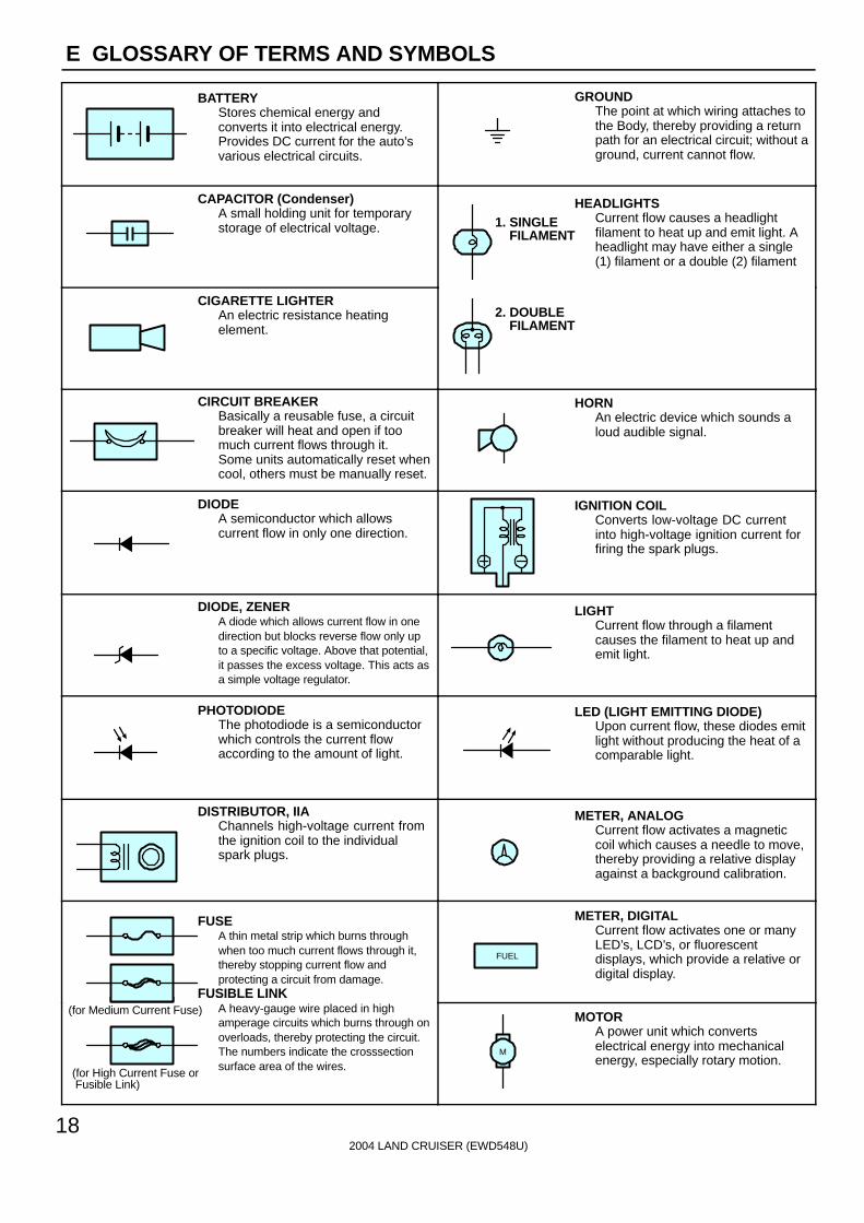
E GLOSSARY OF TERMS AND SYMBOLS
BATTERYStores chemical energy andconverts it into electrical energy.Provides DC current for the auto’svarious electrical circuits.
GROUNDThe point at which wiring attaches tothe Body, thereby providing a returnpath for an electrical circuit; without aground, current cannot flow.
CAPACITOR (Condenser)A small holding unit for temporarystorage of electrical voltage.
HEADLIGHTSCurrent flow causes a headlightfilament to heat up and emit light. Aheadlight may have either a single(1) filament or a double (2) filament
1. SINGLE FILAMENT
CIGARETTE LIGHTERAn electric resistance heatingelement.
2. DOUBLE FILAMENT
CIRCUIT BREAKERBasically a reusable fuse, a circuitbreaker will heat and open if toomuch current flows through it.Some units automatically reset whencool, others must be manually reset.
HORNAn electric device which sounds aloud audible signal.
DIODEA semiconductor which allowscurrent flow in only one direction.
IGNITION COILConverts low-voltage DC currentinto high-voltage ignition current forfiring the spark plugs.
DIODE, ZENERA diode which allows current flow in onedirection but blocks reverse flow only upto a specific voltage. Above that potential,it passes the excess voltage. This acts asa simple voltage regulator.
LIGHTCurrent flow through a filamentcauses the filament to heat up andemit light.
PHOTODIODEThe photodiode is a semiconductorwhich controls the current flowaccording to the amount of light.
LED (LIGHT EMITTING DIODE)Upon current flow, these diodes emitlight without producing the heat of acomparable light.
DISTRIBUTOR, IIAChannels high-voltage current fromthe ignition coil to the individualspark plugs.
METER, ANALOGCurrent flow activates a magneticcoil which causes a needle to move,thereby providing a relative displayagainst a background calibration.
FUSEA thin metal strip which burns throughwhen too much current flows through it,thereby stopping current flow andprotecting a circuit from damage.
FUSIBLE LINK
METER, DIGITALCurrent flow activates one or manyLED’s, LCD’s, or fluorescentdisplays, which provide a relative ordigital display.
FUEL
FUSIBLE LINKA heavy-gauge wire placed in highamperage circuits which burns through onoverloads, thereby protecting the circuit.The numbers indicate the crosssectionsurface area of the wires.
(for Medium Current Fuse)
(for High Current Fuse or Fusible Link)
MOTORA power unit which convertselectrical energy into mechanicalenergy, especially rotary motion.
M
2004 LAND CRUISER (EWD548U)
19
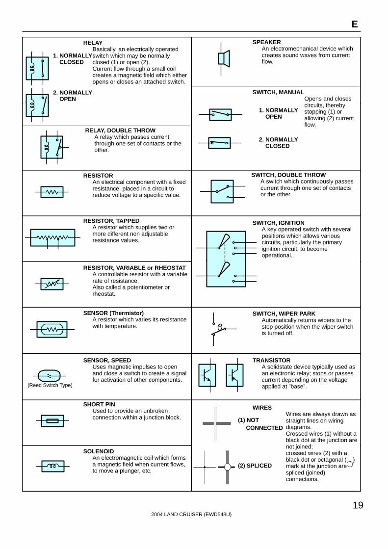
E
RELAYBasically, an electrically operatedswitch which may be normallyclosed (1) or open (2).Current flow through a small coilcreates a magnetic field which eitheropens or closes an attached switch.
1. NORMALLY CLOSED
2. NORMALLY OPEN
SWITCH, MANUALOpens and closesi it th b
SPEAKERAn electromechanical device whichcreates sound waves from currentflow.
RELAY, DOUBLE THROWA relay which passes currentthrough one set of contacts or theother.
circuits, therebystopping (1) orallowing (2) currentflow.
1. NORMALLY OPEN
2. NORMALLY CLOSED
RESISTORAn electrical component with a fixedresistance, placed in a circuit toreduce voltage to a specific value.
SWITCH, DOUBLE THROWA switch which continuously passescurrent through one set of contactsor the other.
RESISTOR, TAPPEDA resistor which supplies two ormore different non adjustableresistance values.
SWITCH, IGNITIONA key operated switch with severalpositions which allows variouscircuits, particularly the primaryignition circuit, to becomeoperational.
RESISTOR, VARIABLE or RHEOSTATA controllable resistor with a variablerate of resistance.Also called a potentiometer orrheostat.
SENSOR (Thermistor)A resistor which varies its resistancewith temperature.
SWITCH, WIPER PARKAutomatically returns wipers to thestop position when the wiper switchis turned off.
(Reed Switch Type)
SENSOR, SPEEDUses magnetic impulses to openand close a switch to create a signalfor activation of other components.
TRANSISTORA solidstate device typically used asan electronic relay; stops or passescurrent depending on the voltageapplied at ”base”.
SHORT PINUsed to provide an unbrokenconnection within a junction block.
WIRESWires are always drawn asstraight lines on wiringdiagrams.Crossed wires (1) without ablack dot at the junction are
t j i d
(1) NOT CONNECTED
SOLENOIDAn electromagnetic coil which formsa magnetic field when current flows,to move a plunger, etc.
jnot joined;crossed wires (2) with ablack dot or octagonal ( )mark at the junction arespliced (joined)connections.
(2) SPLICED
2004 LAND CRUISER (EWD548U)
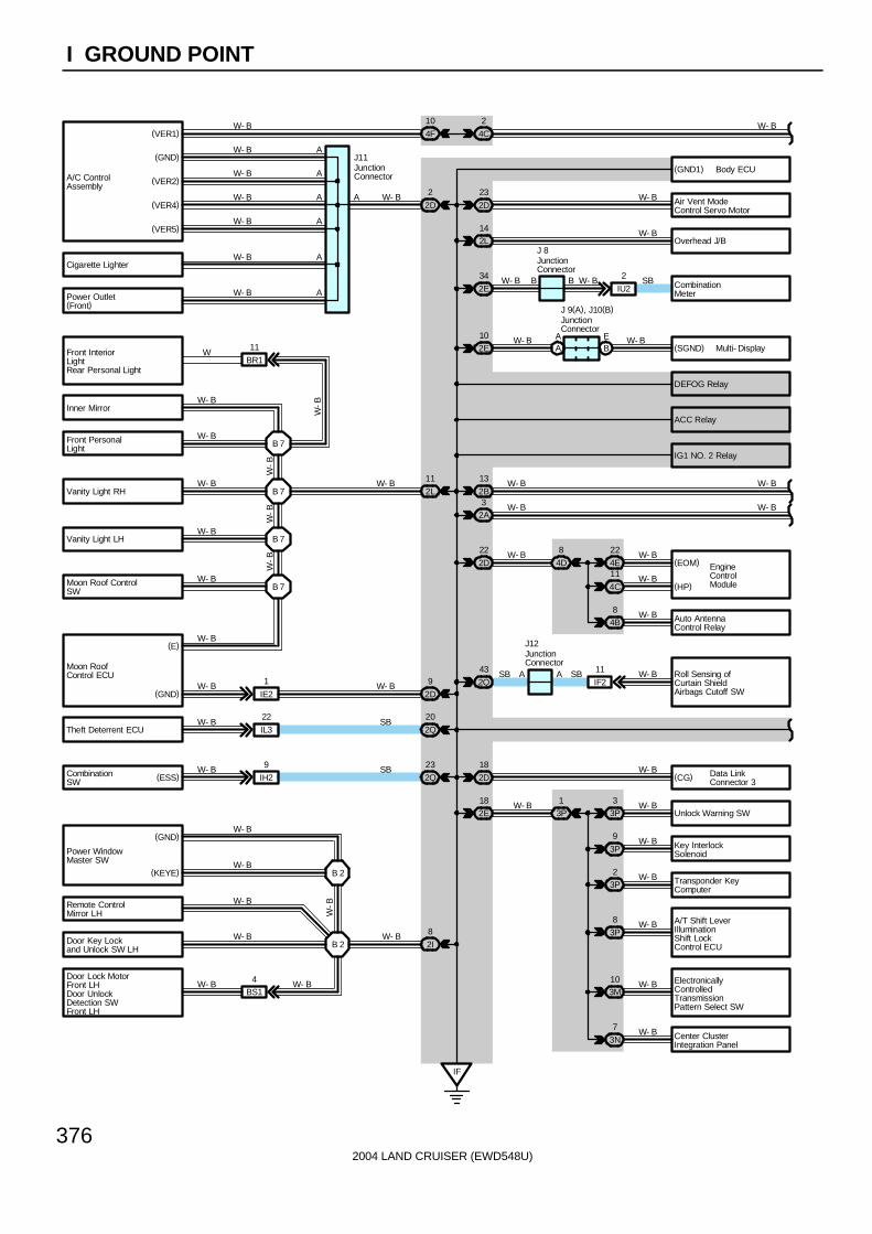
376
I GROUND POINT
(VER4)
(GND)
(VER1)
A/C ControlAssembly
(VER2)
Air Vent ModeControl Servo Motor
Overhead J/B
Unlock Warning SW
EngineControlModule
Cigarette Lighter
Power Outlet(Front)
ElectronicallyControlledTransmissionPattern Select SW
W- B
W- B
W- B
W- B
Auto AntennaControl Relay
W- B
A
A A
J11
W- B
W- B
Key InterlockSolenoid
W- B
Transponder KeyComputer
AW- B
W- B
4C
2
2D
23
2L14
3P3
3P
9
3P2
(VER5)W- B
2D
2
4F
10
Body ECU(GND1)
3P
8
3P1
2E18
A
A
A
W- B
W- B
3M10
IF
W- B
W- B
W- B
W- B
W- B
2D
22
4E
22
4C
11
4B8
4D
8(EOM)
(HP)W- B
W- B
Inner Mirror
Front PersonalLight
Vanity Light RH
Vanity Light LH
Moon Roof ControlSW
Door Key Lockand Unlock SW LH
Door Lock MotorFront LHDoor UnlockDetection SWFront LH
B 7
B 7
W- B
W- B
W- B
W- B
W- B
W- B
W- B
Remote ControlMirror LH
2E
34 SB CombinationMeter
18
2DW- B Data Link
Connector 3(CG)
IU2
2BBW- B W- B
W- B
W- B
W- B
Power WindowMaster SW
(GND)
(KEYE) B 2
B 2
W-B
W- B2I
8
BS14W- B W- B
IE2
1W- B
(E)
Moon RoofControl ECU
(GND)
Front InteriorLightRear Personal Light
B 7
2L
11W- B
BR1
11W
W-B
B 7
2A3
2B
13 W- B
W- B
W- B
W- B
CombinationSW
Theft Deterrent ECU
IH2
9
2Q
23
2Q
20
IL3
22W- B
W- B
SB
SB
DEFOG Relay
ACC Relay
IG1 NO. 2 Relay
Center ClusterIntegration Panel3N
7 W- B
W- B
2D
9W- B
(ESS)
W-B
W-B
W-B
JunctionConnector
A/T Shift LeverIlluminationShift LockControl ECU
2Q
43 W- B Roll Sensing ofCurtain ShieldAirbags Cutoff SW
A AIF2
11SBSB
JunctionConnector
J12
W- B102E
W- BAA
BE
JunctionConnector
J 9(A), J10(B)
JunctionConnector
J 8
Multi- Display(SGND)
2004 LAND CRUISER (EWD548U)
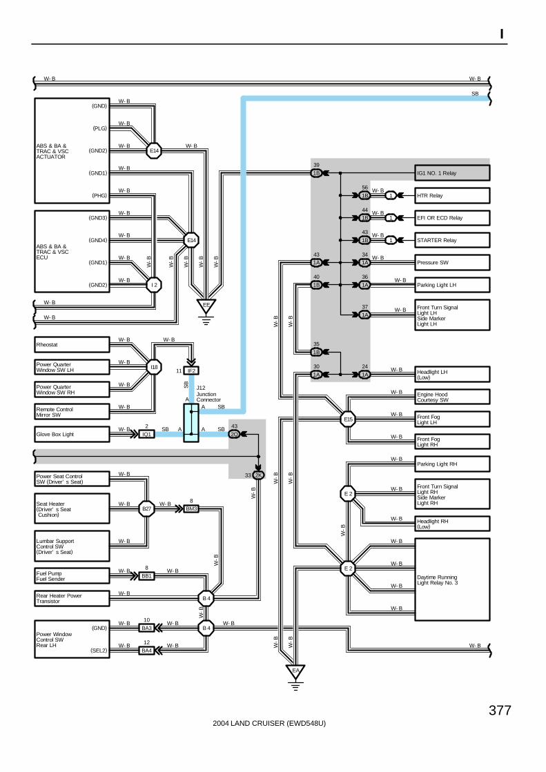
377
I
Seat Heater(Driver’ s Seat Cushion)
Power Seat ControlSW (Driver’ s Seat)
B27W- B
W- B
Lumbar SupportControl SW(Driver’ s Seat)
W- B
BM38W- B
E 2
HTR Relay
Headlight LH(Low)
Parking Light LH
Front Turn SignalLight LHSide MarkerLight LH
Front FogLight LH
Front FogLight RH
Parking Light RH
Front Turn SignalLight RHSide MarkerLight RH
Headlight RH(Low)
Fuel PumpFuel Sender
B 4
1B
56
441B
1B
43
1A
24
1A
36
1A
37
E 2
1A
30
EA
W- B
W- B
W- B
W- B
W- B
W- B
W- B
W- B
W-B
W-B
W- B
Rear Heater PowerTransistor
W- B
W- B
W- B
W- B
W- B
W-B
W-B
W-B
Pressure SW
W- B
W-B
B 4BA3
10W- B
BA4
12W- B
Power WindowControl SWRear LH
W- B
W- B
W-B
(GND2)
(GND1)
(PHG)
(GND3)
(GND1)
(GND)
(PLG)
ABS & BA &TRAC & VSCACTUATOR
(GND4)ABS & BA &TRAC & VSCECU
Rheostat
Power QuarterWindow SW LH
Power QuarterWindow SW RH
Remote ControlMirror SW
(GND2) I 2
E14W- B
W- B
W- B
W- B
W- B
W- B
W- B
W- B
W- B
W- B
W- B W- B
BB1
8
2K33
1A34
1
1
1
W- B
W- B
W- B
IG1 NO. 1 Relay
EFI OR ECD Relay
STARTER Relay
1B
39
W- B
1B
35
1B
40
W-B
Daytime RunningLight Relay No. 3
E15
Engine HoodCourtesy SW
W- B
1A43
W-B
W-B
Glove Box Light 2Q
43
IQ1
2W- B SB SBA A
EE
E14
W- B
W- B
W-B
W-B
W-B
W-B
W-B
SB
A SB
I18IF211
A
SB
W- BW- B
W- B
W- B
W- B
J12
W- B
W- B
JunctionConnector
(GND)
(SEL2)

2004 LAND CRUISER (EWD548U)
378
I GROUND POINT
Turn SignalFlasher
Seat Heater SW(Driver’ s Seat)
Seat Heater SW(Front Passenger’ s Seat)
W- B
W- B
W- B
Power Outlet(Rear Console Box)
Tilt andTelescopic ECU
W- B
W- BJ 3
A
Center AirbagSensorAssembly
Multi- DisplayW- B
IG1 NO. 3 Relay
IP2
2
AF
BH
BH
BH
3D
8
3D
10
3D
42
3D1
AE
BD
BD
II
W- B
W- B
W- B
J 1
J18(A), J19(B)
W- BA A
J 9(A), J10(B)
W- B
3F6
3F
9
IH
(E1)
(E2)
(CG)Gateway ECU
W- B
W- B
3E35 A
A
W-B
Auto Antenna Motor
Front Wiper Motor
Door Key Lock andUnlock SW RH
Door Lock MotorFront RHDoor UnlockDetection SWFront RH
Door LockControl SW RH
(EW)
(TB)
E 53B
1EB
I 9
W- B
W- B
W- B
W- B
A
J16
3K
31 W- B
(EL)
W- B
W- B
W- B
W- B
Towing BrakeController
3I
9 W- BB 8
W- B
W- B
II33
W- B
3Q
58
SB
W- B
SB
3E
34 W- B
Remote ControlMirror RH
W- B
W- B
BT14
W- B
W-B
W- B
3B
2AW- B
W- B
W- B W- B
Data LinkConnector 1
W- B
Gateway ECUW- B
HB
DVD AutomaticChanger A
FW- B
14
2Q
IG
(GND2) Body ECU
3Q
40 W- B
W- B63E Center Diff. Lock
Control Relay
W- B
JunctionConnector
Junction Connector
JunctionConnector
JunctionConnector
Junction Connector
(GND)
Blower MotorController
2
3HW- B
3D
9
Power WindowControl SWFront RH
(GND)
(SEL1)
CombinationSW
CombinationSW
CombinationSW
BR
(GND1)

2004 LAND CRUISER (EWD548U)
379
I
W-B
W- B10W- B
A/C Amplifier(Rear)
Rear CombinationLight RH
Buckle SW RH
Seat Heater (FrontPassenger’ s Seat)
Power Seat ControlSW (FrontPassenger’ s Seat)
Door Lock MotorRear RHDoor UnlockDetection SWRear RH
Trailer Socket
Rear CombinationLight RH
Rear CombinationLight LH
Back Door Key Lockand Unlock SW
Rear WindowDefogger
Back Door LockMotorBack Door UnlockDetection SW
Rear Wiper Motor
High MountedStop Light
Back DoorCourtesy SW
License PlateLight LH
License PlateLight RH
Power Outlet(Luggage Compartment)
Rear CombinationLight LH
B28
B 9
BO38
BK
B14
B16
BL112
B26
BH25
BD210
BM
BP36
W- B
W- B
W- B
BQ2
W- B
W- B
W- B
W- B
W- B
W- B
W- B
W- B
W- B
W- B
W- B
W- B
W- B
W- B
W-B
W-B
W-B
W-B
W-B
W-B
W-B
W-B
B11
Towing ConverterRelay
W- B
NavigationECU W- B
Power WindowControl SW Rear RH
W- BBC3
10W- B
BW1
8W- B W- B
W- B
BO2
4
BV1
1W- B W- BW- B
IV4
18 W- B
W- B
BC414W- B W- B
WW- BBX1
3
B15
Door ControlReceiver
Buckle SW LH
Door Lock MotorRear LHDoor UnlockDetection SWRear LH
BA4
14
BP4
9
BM24
BU11
B 6
B11
W- B
W- B
W- B
W- B
W- B
W- B
W- B
W-B W
-B
W-B
BJ
W-B
W- B W- B
BR
BR BR36Ig1
1IP2 Rear Seat Audio
Controller
BR
BR
BR
B 9
StereoComponentAmplifier
(E)
BL
(GND2)
E
E
W-B
W- B Rear Cooler PowerTransistor
W- B
B14
J25(A)JunctionConnector
W-B
(SNSE)
(GND)
W- B
W- B
BF
AH
BF
AH
AH
BF
JunctionConnector
J23(B), J25(A)
( *1)
( *2)
( *1)
( *2)
Television CameraECU
W- B
Junc
tion
Con
nect
orJ2
2
Towing HitchRelay
W- B E
BH23 (*1)(*2)
* 2 : w/o Navigation System* 1 : w/ Navigation System
AD
AD

2004 LAND CRUISER (EWD548U)
380
I GROUND POINT
5
EngineControlModule
E 9
EC
E10
5
IH2
IX1
8
E10 E10
Ignition Coil andIgniter No. 1
Ignition Coil andIgniter No. 2
Ignition Coil andIgniter No. 3
Ignition Coil andIgniter No. 4
Data LinkConnector 3
CombinationSW
Ignition Coil andIgniter No. 5
Ignition Coil andIgniter No. 6
Ignition Coil andIgniter No. 7
Ignition Coil andIgniter No. 8
Center Diff. LockControl Motor
Detection SW(Transfer Neutral Position)
EB1
Detection SW(Center Diff. Lock)
(E01)
(E02)
(E03)
(ME01)
CombinationMeter
ED
IX25
E10
W- B
W- B
W- B
W- B
W- B
W- B
W- B
BR
SBBR
BR
SB
W-B
BR
SB
BR
W-B
W- B
W- B
W- B
W- B
W- B
W- B
W- B
W- B
W- B
W-B
BR
E10
E10
Vehicle SpeedSensor(Combination Meter)
BR
BR
BR
BR
(SG)
A/C Magnetic ClutchA/C Lock Sensor
EB19 W-B
IX19
3Q53
3E10
W-B
W- B Noise Filter(Ignition)
(ECC)
BR(E1)E10
BR BR
BR
BR

2004 LAND CRUISER (EWD548U)
381
I
: Parts Location
Code See Page Code See Page Code See Page
J1 71 J11 71 J22 72
J3 71 J12 71 J23 B 72
J8 71 J16 71 J25 A 72
J9 A 71 J18 A 71
J10 B 71 J19 B 71
: Relay Blocks
Code See Page Relay Blocks (Relay Block Location)
1 22 Engine Room R/B (Engine Compartment Left)
: Junction Block and Wire Harness Connector
Code See Page Junction Block and Wire Harness (Connector Location)
1A 24 Engine Room Main Wire and Engine Room J/B (Engine Compartment Left)
1B 24 Engine Room No.2 Wire and Engine Room J/B (Engine Compartment Left)
2A28 Engine Room No 2 Wire and Cowl Side J/B LH (Left Kick Panel)
2B28 Engine Room No.2 Wire and Cowl Side J/B LH (Left Kick Panel)
2D28 Dash Wire and Cowl Side J/B LH (Left Kick Panel)
2E28 Dash Wire and Cowl Side J/B LH (Left Kick Panel)
2I 28 Front Door LH Wire and Cowl Side J/B LH (Left Kick Panel)
2K 28 Floor No.1 Wire and Cowl Side J/B LH (Left Kick Panel)
2L 28 Roof No.1 Wire and Cowl Side J/B LH (Left Kick Panel)
2Q 30 Instrument Panel Integration Wire and Cowl Side J/B LH (Left Kick Panel)
3B 40 Engine Room No.2 Wire and Cowl Side J/B RH (Right Kick Panel)
3D
3E40 Dash Wire and Cowl Side J/B RH (Right Kick Panel)
3F40 Dash Wire and Cowl Side J/B RH (Right Kick Panel)
3H
3I 40 Front Door RH Wire and Cowl Side J/B RH (Right Kick Panel)
3K 40 Floor No.2 Wire and Cowl Side J/B RH (Right Kick Panel)
3M
3N 43 Dash Wire and Cowl Side J/B RH (Right Kick Panel)
3P
( g )
3Q 42 Instrument Panel Integration Wire and Cowl Side J/B RH (Right Kick Panel)
4B
4C
4D 52 Dash Wire and J/B No.4 (Instrument Panel Center)
4E
( )
4F

2004 LAND CRUISER (EWD548U)
382
I GROUND POINT
: Connector Joining Wire Harness and Wire Harness
Code See Page Joining Wire Harness and Wire Harness (Connector Location)
EB1 76 Engine Wire and Transmission Wire (On the Transmission)
IE2 78 Dash Wire and Roof No.1 Wire (Left Kick Panel)
IF2 78 Instrument Panel Integration Wire and Instrument Panel Wire (Left Side of Instrument Panel)
IH2 80 Instrument Panel Integration Wire and Column Wire (Near the Ignition SW)
II3 80 Dash Wire and Column Wire (Near the Ignition SW)
IL3 80 Instrument Panel Integration Wire and Computer Wire (Instrument Panel Center)
IP2 80 Rear Console Box Wire and Dash Wire (Right Side of Rear Console)
IQ1 80 Instrument Panel Integration Wire and Lamp Wire (Behind the Glove Box)
IU2 82 Instrument Panel Integration Wire and Dash Wire (Behind the Glove Box)
IV4 82 Dash Wire and Floor No.2 Wire (Right Kick Panel)
IX182 Instrument Panel Integration Wire and Engine Wire (Behind the Glove Box)
IX282 Instrument Panel Integration Wire and Engine Wire (Behind the Glove Box)
Ig1 84 Dash Wire and Floor No.2 Wire (Right Side of Front Console)
BA386 Rear Door LH Wire and Floor No 1 Wire (Left Side of Center Pillar)
BA486 Rear Door LH Wire and Floor No.1 Wire (Left Side of Center Pillar)
BB1 86 Floor No.1 Wire and Fuel Tank Wire (Near the Fuel Tank)
BC386 Rear Door RH Wire and Floor No 2 Wire (Right Side of Center Pillar)
BC486 Rear Door RH Wire and Floor No.2 Wire (Right Side of Center Pillar)
BD2 86 Floor No.3 Wire and Floor No.1 Wire (Left Rear Side Quarter Panel)
BH2 86 Pillar No.1 Wire and Back Door Upper Wire (Left Side of Back Door)
BL1 88 Floor No.2 Wire and Floor No.3 Wire (Right Side of Rear Floor Crossmember)
BM290 Floor No 1 Wire and Front Seat LH Wire (Front Side Under the Driver’s Seat)
BM390 Floor No.1 Wire and Front Seat LH Wire (Front Side Under the Driver’s Seat)
BO290 Floor No 2 Wire and Front Seat RH Wire (Front Side Under the Front Passenger’s Seat)
BO390 Floor No.2 Wire and Front Seat RH Wire (Front Side Under the Front Passenger’s Seat)
BP388 Pillar No 1 Wire and Floor No 1 Wire (Left Rear Side Quarter Panel)
BP488 Pillar No.1 Wire and Floor No.1 Wire (Left Rear Side Quarter Panel)
BQ2 88 Back Door Lower Wire and Floor No.1 Wire (Left Rear Side Quarter Panel)
BR1 88 Roof No.3 Wire and Roof No.1 Wire (Front Side of Roof)
BS1 88 Door Lock LH Sub Wire and Front Door LH Wire (Front Door LH)
BT1 88 Door Lock RH Sub Wire and Front Door RH Wire (Front Door RH)
BU1 88 Floor No.1 Wire and Floor No.1 Wire (Near the Left Rear Suspension Support)
BV1 88 Floor No.2 Wire and Floor No.2 Wire (Near the Right Rear Suspension Support)
BW1 88 Floor No.2 Wire and A/C Sub Wire (Right Side Rear Quarter Panel)
BX1 88 Frame No.4 Wire and Floor No.3 Wire (Left Side of Rear Floor Crossmember)
: Ground Points
Code See Page Ground Points Location
EA76 Front Right Side of Fender Apron
EB76 Front Right Side of Fender Apron
EC 76 Rear Bank of Right Cylinder Head
ED 76 Rear Bank of Left Cylinder Head
EE 76 Front Left Side of Fender Apron
IF78 Set Bolt of Cowl Side J/B LH
IG78 Set Bolt of Cowl Side J/B LH
IH78 Set Bolt of Cowl Side J/B RH
II78 Set Bolt of Cowl Side J/B RH
BJ 86 Under the Driver’s Seat
BK 86 Front Side Under the Front Passenger’s Seat
BL 86 Rear Side Under the Front Passenger’s Seat
BM 86 Left Rear Side Quarter Panel
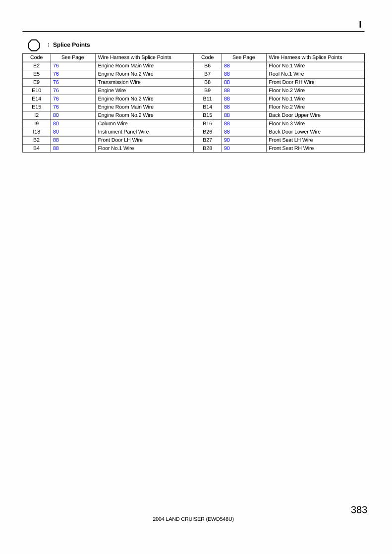
2004 LAND CRUISER (EWD548U)
383
I
: Splice Points
Code See Page Wire Harness with Splice Points Code See Page Wire Harness with Splice Points
E2 76 Engine Room Main Wire B6 88 Floor No.1 Wire
E5 76 Engine Room No.2 Wire B7 88 Roof No.1 Wire
E9 76 Transmission Wire B8 88 Front Door RH Wire
E10 76 Engine Wire B9 88 Floor No.2 Wire
E14 76 Engine Room No.2 Wire B11 88 Floor No.1 Wire
E15 76 Engine Room Main Wire B14 88 Floor No.2 Wire
I2 80 Engine Room No.2 Wire B15 88 Back Door Upper Wire
I9 80 Column Wire B16 88 Floor No.3 Wire
I18 80 Instrument Panel Wire B26 88 Back Door Lower Wire
B2 88 Front Door LH Wire B27 90 Front Seat LH Wire
B4 88 Floor No.1 Wire B28 90 Front Seat RH Wire

2004 LAND CRUISER (EWD548U)
Memo

2004 LAND CRUISER (EWD548U)
M OVERALL ELECTRICAL WIRING DIAGRAM
12
34
1 L
AN
D C
RU
ISE
R( C
ont.
nex
t pa
ge)
2A
1C
1A
1B
7. 5A AM1
2C1
2E39
12
53
12
53
2E40
IFSe
t Bol
t of C
owl S
ide
J/B
LH
7. 5A ACC
2Q57
10A GAUGE1
2Q65
2E37
2Q77
2 7
AC
C
IG1
IG2
ST2
AM1
3 4 6AM
2
6B5
6D2
6B4
6D3 4
IX1
AA 3E4
3Q50
3Q51
34
21
12
35
3Q39
3C1
7. 5ASECURITY
20A P/W (FR)
3E16
2
IIS
et B
olt o
f Cow
l Sid
eJ/
B R
H
3Q52 3
IX1
Bat
teryB- G
B- G
B- R
L- B
SB
B- R
I18
B- R
SBB
IG1
NO
. 3R
elay
AC
CC
UT
Rel
ay
SB
B-R
SB
B- GB
-R
ACC Relay
120A
MAI
N
120A
J/B
NO
. 3
120A
J/B
NO
. 1
140A
ALT
120A
J/B
NO
. 2
F15(
A) ,
F16(
B), F
17( C
)
B- G
B- G
10A ECU- IG1
2I1
2Q21
35
21
4
20A
DEF
OG
IG1
NO
. 2R
elay
2D24
7. 5A IDLE UP
2G2
DEFOG Relay
3Q7
3I1
3E1
3K37
3E33
7. 5A MET
10A GAUGE2
20A P/W (FL)
20A P/W (RR)
20A P/W (RL)
LM
NO
PAB D
C EF G I
H
KAA
LG
L
L
L
L
SB
SB
B
SB
B- W
SB
SB
B- R
W-R
L-BB
Rea
r W
indo
wD
efog
ger S
yste
m<
11-2
>
J14
J 4
Engine ControlSystem<4- 2>
L L SB LLLGW-RBSB
B-WSB
SB
B-G
B-G
Po
we
r S
ou
rce
3Q72
3I
L
J
SB
SB
B-R
Igni
tion
SW
JunctionConnector
Fusi
ble
Link
Blo
ck
JunctionConnector
25A DOOR
2210 12
SIG
AC
C
BD
R1
Body ECU
B
6 7A
7A5
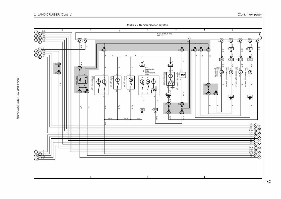
2004 LAN
D C
RU
ISE
R (E
WD
548U)
M
5 6 7 8
1 LAND CRUISER (Cont’ d) (Cont. next page)
LMRY
B
EF
GH
IJ
KL
MN
O
M u ltip lex Communication S ystem
B 7(A), B 8(B), B 9(C)
L
W- R
LSB
B
L
B- W
G
BC
E
PO
NM
L L
D
F
A
IH
K
LG
SB
SBSB
B- GB- G
3 A
2E41
2A10
DC
A
J SB
L B- GB- GW- R
LSBSBSBLLLL
B- WSBSBLG
4
31
WWW
G-W
R R
RRRR
BR15
2L18
BR1
R27
G-Y
4
BR19BR111
2E22
F10
V 7
V 6
T10
BR18
2L8
F11
R
G-W
R
15 2E
2I4
1
2
5
3
2Q792K9
27 A
DEF
B
2E12
27 2Q
SB
3K22 7 3J
3Q80
22 2K
R
R R R
W- BW- BW- B
W-B
W-B
W-B
W-B
DO
ME
Relay
13
ILE
PQ
R
W- BSBL- Y
SB
L-Y
W-R
R-W
2G1
G-Y
G-R
ID420
BC4212 IY2
1
2
1
2
25 A 22 B
D11
D13
IV4
IC212
1
2
26 AD
10
BA42
1
2
1 BA4
21 B
D12
G-B
RG
-R
G-B
G-R
PCYL
8
RCYL DCYL LCYLR
R
G-W
G-Y
G-W
G-R
R
BC4
R
1
RRR
2L3
G-W
G-Y
OFF
DO
OR
ON
6 B
LP
G-Y
2
6
Door C
ourtesy Light Front LH
Door C
ourtesyLight Front R
H
Door C
ourtesy Light Rear LH
Door C
ourtesy Light Rear R
H
Front Personal Light
Rear Interior Light
Ignition Key C
ylinder Light
Vanity Light LH
Vanity Light R
H
Body ECU
Front InteriorLightRear PersonalLight
2
1
DO
OR
OFFO
N
WW
2
1
2
1
2
1
R-W
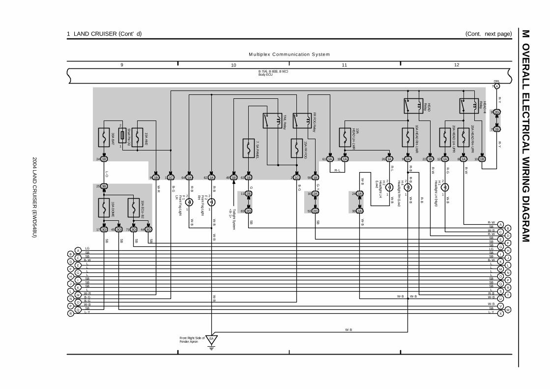
2004 LAN
D C
RU
ISE
R (E
WD
548U)
M O
VE
RA
LL ELE
CT
RIC
AL W
IRIN
G D
IAG
RA
M
M ultip lex Communication S ystem
11 12109
(Cont. next page)1 LAND CRUISER (Cont’ d)
10AH
EAD
LH-LW
R
1A
1
2
10A H
EAD
RH
-LWR
1A
20A H
EA
D R
H-U
PR
1A
H 2
1
2H 4
1
2H 1
R-L
R-B
R-G
AB
CD
EF
GH
IJ
KL
MN
OP
QR
LGSBSB
LLLL
SBSBSBL
W- RB- GB- GW- BSBL- Y
B 7(A), B 8(B), B 9(C)
FG
HI
JK
LM
NO
PQ
RS
SBSBLGSBSB
LLLL
SBSBL
R- B TW- B
26 9 8
1
2F 1
1
2F 2
R-B
R-B
W-B
EAFront Right Side ofFender Apron
W-B
W-B
1A64 1A62 2
15A FR
FOG
1C 1B59
1A61 1A19
2A16
2Q53
FR FO
G R
elayG
-YS
B
R- L
R-B
B- W
1C1
15A A
M2
1B9
30A B
AT
1B24
10A DO
ME
10A EC
U-B
2
3Q17 3Q45 3Q71 3Q44
3B25
ESBDR- W CW- B
U
VW
X
W- BSBL- Y
1B22 1B10
7 A
2G9
2B7
SB
B- W
R-Y
R-Y
R-W
W-B
W-B
R-B
W-B
W-B
B-G
B-G
W-R
L-O
SB
SB
SB
SB
W- B
W- B W- B
Short P
in (A )
W-B
HEA
D H
IR
elay
HE
ADR
elay
DRL
1
2
TAIL R
elay
7. 5A P
ANE
L
1B49 1B63
1A24
1A30
W-B
B
Taillight System
<8-1>
SB
G
2B11
2Q83
SB
Front Fog LightLH Front Fog LightR
H
Headlight LH
(High )
Headlight LH
(Low)
Headlight R
H (Low
)
Body ECU
12
20A H
EAD
LH-U
PR
1A
A
R-W
R- W
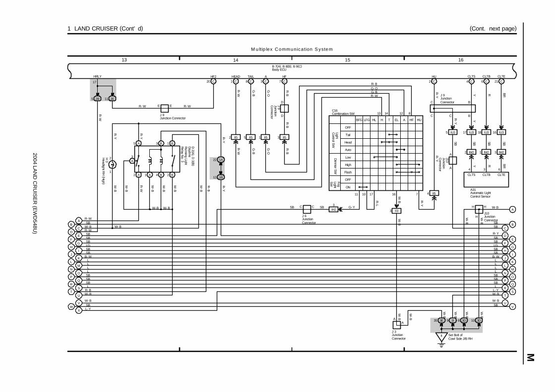
2004 LAN
D C
RU
ISE
R (E
WD
548U)
M
15 161413
(Cont. next page)1 LAND CRUISER (Cont’ d)
1
2
1413
711
A HU
Dim
mer S
WLightC
ontrol SW
ON
Head
Auto
Low
OFF
Tail
High
Flash
OFFFogLightS
W
12 8
EL HFTHHLLFGBFG
1 C 8 C 3 C 7 C
R- WG- BG- OR- B
G-O
G-B
R-W
R-W
G-B
G-O
R-B
HEAD TAIL A HF
R-Y
FG
HI
JK
LM
NO
PQ
RS
U
SBLGSBSB
LLLL
SBSBL
R- BW- B
M u ltip lex Communication S ystem
DE
F
IJ
KL
MN
OP
QR
R- YSBSB
SB
LLLL
SBSBSBL
B 7(A), B 8(B), B 9(C)
TTW- B
UV
W- BSB
2 II5 5 II5 1 II5 3 II5
R-B
J13
10 17
R-L
4 II5
R-Y
H 3
C CSB SB G- YIH23
R-Y
W-B
1A22
1B13
R-Y
DE SB
C W- B
GH
LGSB
B- WB- W
SB
SB
R- W
VW- BSBWL- YX
2B5 2E11
20 C
HF2
17
E ER- W R- W
HRLY
R-W
W-B
II Set Bolt ofCowl Side J/B RH
3E35 3I9
3 II3
2 C
HU
C16
16
C
C
A
W-B
R-Y
R-Y J 9
J 3
W-B
W-B
R-B
J 9W
-B
SL- Y
W-B
A
W-B
W-B
W-B
BB SB
17 IU3 18 IU3 16 IU3
4 C 6 C 21 C
4 3 6
A31
CLTS CLTB CLTE
CLTS CLTB CLTE
Y R BR
Y R BR
Y
SBSBSB
IM23IM21IM22
CSBSB
C
SB
B
B
5 IU3
R-Y
A
A
J 9
D
D
J 6
W-B
3D8
W-B
3D10
H
AH H W- B
W-B
W-B
J10
Automatic LightControl Sensor
Combination SW
Headlight R
H (H
igh )
Body ECU
JunctionC
onnector
JunctionConnector
Junction Connector
JunctionConnector
JunctionConnector
JunctionConnector
JunctionC
onnector
1 A2 A 4 B
3A
R-B
2 B
AR- W
W-B
R-W
W-B
5 A
R-Y
W- B W- B
W- B
1 B3 B Daytim
eR
unning LightR
elay No. 3
D 2 (A
), D 3 (B
)
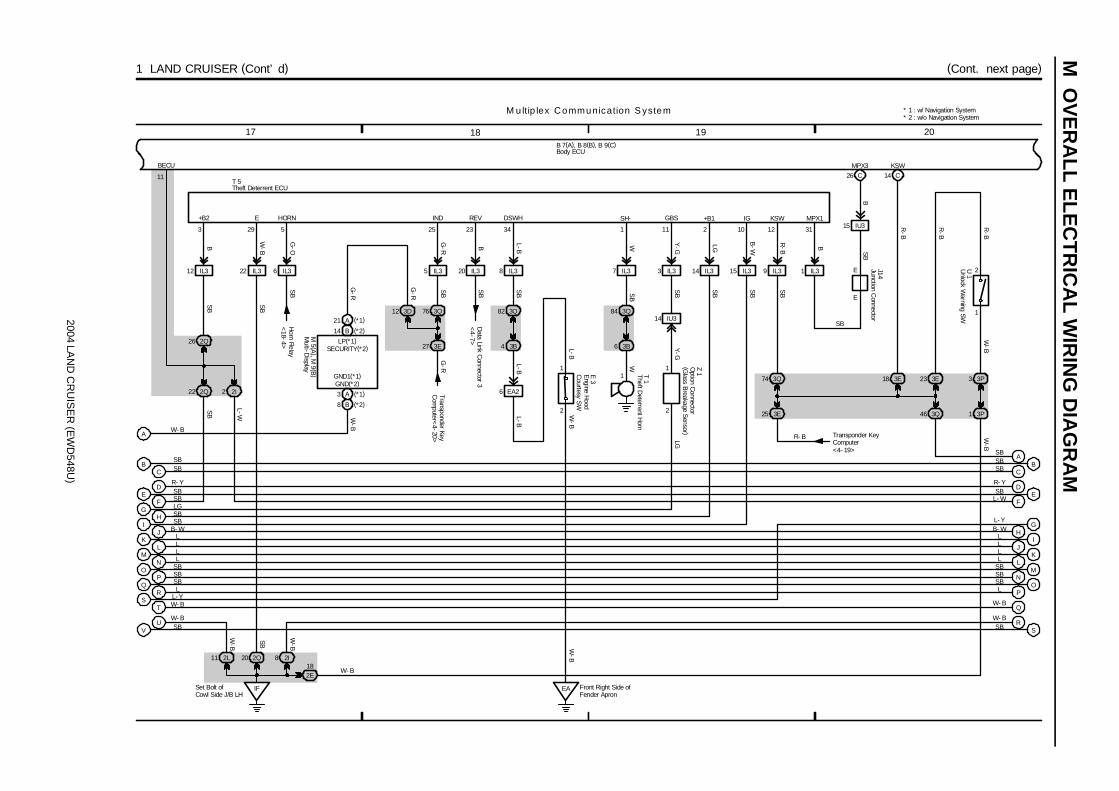
2004 LAN
D C
RU
ISE
R (E
WD
548U)
M O
VE
RA
LL ELE
CT
RIC
AL W
IRIN
G D
IAG
RA
M
19 201817
(Cont. next page)1 LAND CRUISER (Cont’ d)
1 T 1
1
14 C
2 10
26 C
1
2U 1
SH-
WS
B
KSW+B1 IG MPX1
KSWMPX3
R-B
B
R-B
R-B
W-B
T 5
QP
ON
ML
KJ
IH
GF
ED
R- YSBSBLG
SBB- W
LLLL
SBSBSB
B 7(A), B 8(B), B 9(C)
M u ltip lex Communication S ystem
EF
IJ
K
MN
OPL
SBL- W
LLL
SBSBSB
SR L
L- Y
QW- B
T W- B
RS
W- BSB
SB
SB
J14E
E
1 IL3
15 IU3
3E18 3E23
SB
GH
L
D
B- WL- Y
R- Y
L
IFSet Bolt ofCowl Side J/B LH
2Q202L11 2I8
3P3
3P1
22 IL3
VU
W- BSB
12 IL3
2Q22
2Q26
2I2
8 IL3
3Q82
3B4
182E
6 IL3
6 EA2
2
1
5 IL3
EA Front Right Side ofFender Apron
7 IL3
3B6
3Q84
3 IL3
14 IU3
14 IL3 15 IL3 9 IL320 IL3
3Q74
3E25
3112113423255293
2
1
GBSDSWHREVINDHORNE+B2
W- B
R- B
B
W-B
G-O
G-R B L-B
Y-G
LG
B-W
R-B B
SB
Y-GLG
SB
SB
SB
W
SB
L-BL-B
W-B
SB
SB
SB
SB
SB
SB
L-WW
-B
SB
W-B
W-B
BECU
11
Horn R
elay<
18-4>
Data Link C
onnector 3<
4-7>
E 3
W-B
Transponder KeyComputer<4- 19>
Z 1
L-B
CB
CB
SBSB
SBSB
3Q76
3E27
3D12
14 B (*2)
21 A (*1)
3 A (*1)
8 B (*2)
A
Transponder KeyC
omputer<
4-20>
G-R
G-R
G-R
W-B
LP(*1)SECURITY(*2)
GND(*2)GND1(*1)
M 5 (A
), M 9 (B
)
W- B
* 1 : w/ Navigation System* 2 : w/o Navigation System
3Q46
ASB
Engine H
oodC
ourtesy SW
Multi-D
isplay
Theft Deterrent H
orn
Theft Deterrent ECU
Unlock W
arning SWBody ECU
Junction Connector
Option C
onnector(G
lass Breakage S
ensor )
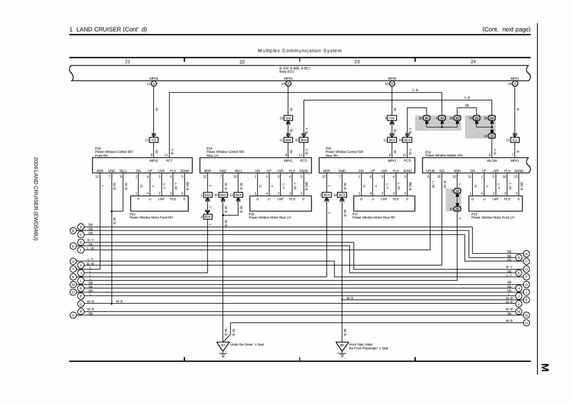
2004 LAN
D C
RU
ISE
R (E
WD
548U)
M
23 242221
(Cont. next page)1 LAND CRUISER (Cont’ d)
SBSBSB
LL
LPO
NM
KJ
I
D
P12
M u ltip lex Communication S ystem
B 7(A), B 8(B), B 9(C)
D
F
GH
IJ
K
R- YSBL- Y
SBSBSBL
W- B
Q
SBW- B
SR M
N
W- BSB
BR
-B
L-W
L-YYG
P15
54361
53241 1 4 2 3 5
1 6 3 4 5
P16
G Y L-Y
L-W
BR
-B
BR
-B
L-W
L-YYG
P17
54361
532411 BC4
10 BC411 BC4
Y-B
WW Y-B
BA411 10 BA4
L
BA31
BD44
11 IY22J10
2K262Q74
W Y-B
W WY-B
Y-B
2I7
2E42
10
118 8 11 8 11 6
SB
Y- B
Y-B
9 20
L
L-W
B-W
L
L
L
19 ID4 9 IV4
Y- B
11 A 14 B 16 B
MPX4 MPX5 MPX6
W W W
FE
HG
L
W- B
L
LB- WL- Y
L- W
R- YSB
12
L
W-B
7 9
W-B
L
12 12
L
3Q193J43K30
10 BA3 12 BA4
W-B
7 10
W-B
BJ Under the Driver’ s Seat BK Front Side Underthe Front Passenger’ s Seat
10 BC3
7
W-B
W-B
P18 P19 P20
LW- B
OW- B
E
1
P14
324
G Y L-Y
L-W
BR
-B
5
11 1 5 15 13
B
IC211
A24
7
MPX1
B
W- BW- B
W-B
W-B
W-B
W-B
W-B
W-B
CB
BCSB
SB
SBSB
A
ASB
SB
BDR GND SEL1 DN UP LMT PLS SGND
MPX1 PCT
BDR GND SEL2 DN UP LMT PLS SGND
MPX1 PCTI
D U LMT PLS E
BDR GND DN UP LMT PLS SGND
MPX1 PCTI
CPUB SIG BDR DN UP LMT PLS SGND
WLSW MPX1
D U LMT PLS ED U LMT PLS EP U LMT PLS E
Power Window Master SW
Power Window Motor Front LHPower Window Motor Front RH Power Window Motor Rear LH Power Window Motor Rear RH
Power Window Control SWFront RH
Power Window Control SWRear LH
Power Window Control SWRear RH
Body ECU
W-B
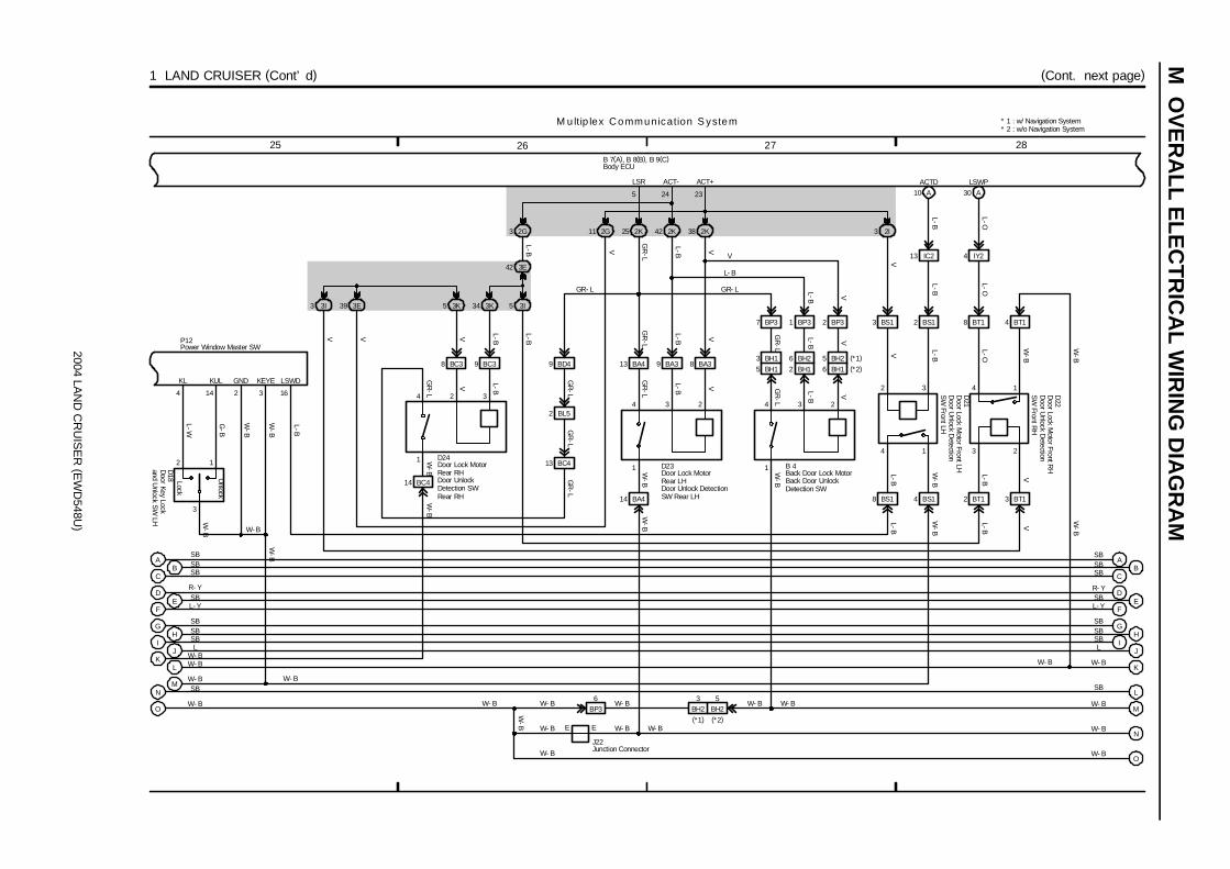
2004 LAN
D C
RU
ISE
R (E
WD
548U)
M O
VE
RA
LL ELE
CT
RIC
AL W
IRIN
G D
IAG
RA
M
27 282625
(Cont. next page)1 LAND CRUISER (Cont’ d)
V L-B
GR
-L
V
GR
-L
V L-B VL-B
ACTD
L-B
L-B
L-B
D23
2 3
5 3K 34 3K
BC38 BC39
BC413
234
3 2I38 2K42 2K
BA38BA39BA413
A10
2 3
BS13
IC213
DE
F
GH
R- YSBL- Y
SBSB
M u ltip lex Communication S ystem
B 7(A), B 8(B), B 9(C)
DE
F
GH
I
R- Y
L- Y
SBSBSB
25 2K
V
GR
-L
2 BL5
9 BD4
GR
-LG
R-L
VL-B
GR
-L
GR- L
L- B
V
2 BS1
L-BV
L-B
16
4
3E42
2G3
L-B
IJ
SBL
W- BW- B
LK
MW- B
W- B
SB
O
N
J
K
LSB
M
W- B
SB
L
W- B
G-B
L-W
4 14
D18
4 BS18 BS1
3
W-B
2
W-B
3I53E39
V
GR
-L
L-B
B 4
234
7 BP3 1 BP3 2 BP3
2G11
3I3
L-OIY24
8 BT1
4
L-O
2 BT1 3 BT1
LSWP
L-O
A30
1 3 2
5 24 23
LSR ACT- ACT+
W- B
W- B
W- B
VL-B
GR
-L
VV
W-B
L-B
W-B
L-B V
L-B
W-B
L-B V
W-B
W-B
P12
L-B
14 BA4
NW- BE
14 BC4
E
BP36
W-B
W-B
W-B
GR
-LW
-B
L-B V
W- BW- BW- B
W- B W- BW- B
W- BW- B
111
D24
D21
D22
J22
GR- L
V
OW- BW- B
Unlock
Lock
3
2 1
BC
BCSB
SBSBSB
4
W-B
A ASB SB
KL KUL GND KEYE LSWD
Back Door Lock MotorBack Door UnlockDetection SW
Door Key Lock
and Unlock S
W LH
Door Lock M
otor Front LHD
oor Unlock D
etectionS
W Front LH
Door U
nlock Detection
SW
Front RH
Door Lock MotorRear LHDoor Unlock DetectionSW Rear LH
Door Lock MotorRear RHDoor UnlockDetection SWRear RH
Power Window Master SW
Body ECU
Junction Connector
W-B
Door Lock M
otor Front RH
1
4 BT1
W-B
W-B
5 BH1
BH13
2 BH1
BH26
6 BH1
BH25 (*1)
(*2)
BH253
BH2(*2)(*1)
* 1 : w/ Navigation System* 2 : w/o Navigation System

2004 LAN
D C
RU
ISE
R (E
WD
548U)
M
31 323029
(Cont. next page)1 LAND CRUISER (Cont’ d)
R-G
R-L
R-G
R-L
SB
RRCYRLCYPCTYDCTY
VV
L
PRGRDA
L
IV37ID415
B12B11B24
D17
1
D16
1
D15
1
D14
1
B23B3B4
32
DE
F
GH
I
R- YSBL- Y
SBSB
C
M u ltip lex Communication S ystem
B 7(A), B 8(B), B 9(C)
L V
R-Y
R-B
R-BR
-Y
2E8 3E15
2K10 3K26
8 BP4 3 BP4
17 ID4 18 ID4
BCTY
B7
16 ID4
11 BP4
B 2
2
C
C
R-L
R-L
R-L
R-L
R-L
J22
6 IG1
R-Y
8 3I
3J133I7
G-W
G-O
L-W
3 1 2
29 2K
L-W
1 BQ2
L-W
3Q413Q35
2Q9 2Q10 3Q30 2Q11
14 3J
G-B
1
3E40
UL2
G-B
A22
3Q42
10 BQ22 BQ2
2Q12
2K24
J L
KW- B
SBL
N
M
W- B
W- B
SB
1 BP4 9 BP4
2E16
I
H
G
F
E
4 IU4
4 2
3 5 1
201519
1
L1 UL1 L2
SB
SB
SB
SB
SB
R-Y
W-B
L-Y
W-B
G-B
L-Y
W-B
W-B
G-B
W-B
SB
L-W
W-B
L
G-B
R-Y
SB
SB
W- B
W- B
SB
D20
D19
B 3
W- B
D27
Transponder KeyC
omputer<
4-19>
OW- B
Unlock
Lock
Lock
Unlock
Lock
Unlock
1
3 2
G-B
BC
BSB
SB
SBSB
DSB
A
A
SB
SBW
-B
Back D
oorC
ourtesy SW
Back D
oor Key Lock
and Unlock SW
Door C
ourtesy SWFront LH
Door C
ourtesy SWFront R
H
Door C
ourtesy SWR
ear LH
Door C
ourtesy SWR
ear RH
Door K
ey Lock andU
nlock SW R
H
Door Lock C
ontrol SW R
H
Body ECU
JunctionC
onnector
Door C
ontrolR
eceiver
E+B
RDA PRG
4 HB2
HB15 (*1)
(*2)
* 1 : w/ Navigation System* 2 : w/o Navigation System
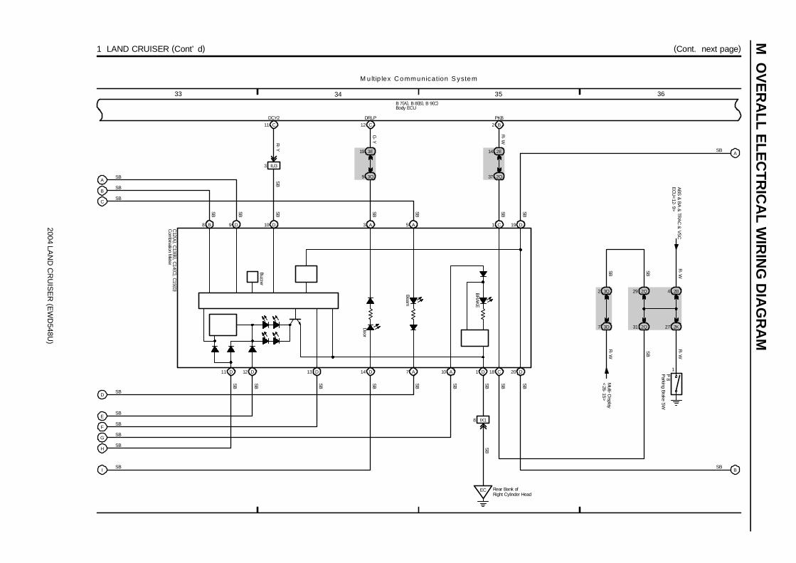
2004 LAN
D C
RU
ISE
R (E
WD
548U)
M O
VE
RA
LL ELE
CT
RIC
AL W
IRIN
G D
IAG
RA
M
35 363433
(Cont. next page)1 LAND CRUISER (Cont’ d)
M u ltip lex Communication S ystem
A
H
B
IX18
C
F
G
EC
I
E
B 7(A), B 8(B), B 9(C)
SB
1
10D 12 D A
Door
Beam
BR
AKE
13 D 14 D 7 A
10 D 3 A 5 A8 B
11
D19C
IU3
R-Y
3
DCY2
C11
SB
SB
SB
18 C 20 D
D
SB
SB
SB
1 D
SB
SB
SB
SB
SB
SBSB SBSB
SBSBSBSB SBSBSBSB
3E
G-Y
19
DRLP
C12
3Q9
SB
9 D
SB
ASB
BSB
2Q
R-W
P 8
31
1
27 2K
4 2B29 2Q
SB
2E
R-W
14
PKB
B2
2Q37
3D7
2 3Q
R-W
SB SB
R-W
ABS
& B
A &
TRA
C &
VSC
EC
U<
12-9>
Multi-D
isplay<
26-15>
SB
Parking Brake S
W
Body ECU
C12 (A
), C13 (B
), C14 (C
), C15 (D
)C
ombination M
eter
Buzzer
Rear Bank ofRight Cylinder Head

2004 LAN
D C
RU
ISE
R (E
WD
548U)
M
39 403837
1 LAND CRUISER (Cont’ d)
IGSet Bolt ofCowl Side J/B LH
B 7(A), B 8(B), B 9(C)
M u ltip lex Communication S ystem
B
A
9 IU1
4F3
2E24
4C12
2Q66
Set Bolt ofCowl Side J/B LH
IF
GND2 GND1
16 4
MPX1
BB
P-B
MPX2
E 8
SB
SB
SB
Moon R
oof Control EC
U<
17-3>
28
IDL
A
Taillight System
<8-1>
7 2Q
2B24
22
2L9
2G4
1823
MPX2
A 21
3Q37
3F7
TRLYPWS
BB
SB
L
C26
10 5C
5B1
15
ELS1
A
G-W
Engine Control M
odule<
4-14>G
-W
6 4E
4A10
4 4E
4C3
B P-B
B P-B(*1 )
(*1 )(*1 )
(*1 )
MPX+ MPX-
MPD1 MPD2
A45
G 4
29
19 39
18
4 11
MPX2
(w/ S
ide Airbag )
* 1 : w/ Navigation System
ACAN
SB
IU32
TC
B
C18
Rheostat
<9-3>
Buckle SW LH
<25-3>
SB
G-W
V-W
W-L
LPOBD2
B
C5
Generator
<2-3>
Park/Neutral P
osition SW<
5-10>
Data Link C
onnector 3<
4-8>
A14B17C17
DBKL
G
A
4 IU3
Center AirbagSensorAssembly
Engine C
ontrolM
odule
Gateway ECU
A/C Control Assembly
Body ECU
SB
3E
3E
21
26
W-L
4A8
4A
A/C C
ontrolAssem
bly<31-14>
17
W-L
13
Com
bination Meter S
ystem<
30-6>
14
SPD
3D
W-L
13
Multi-D
isplay<
26-15><
29-4>
Body E
CU
<1-1>
122210
BDR1ACCSIG
3
STPI
Stop Light System
<10-4>
4B
W-L
6
Radio and Player
<26-8>
<27-4>
MPX1
3
3D41
B
T 7Tilt andTelescopic ECU
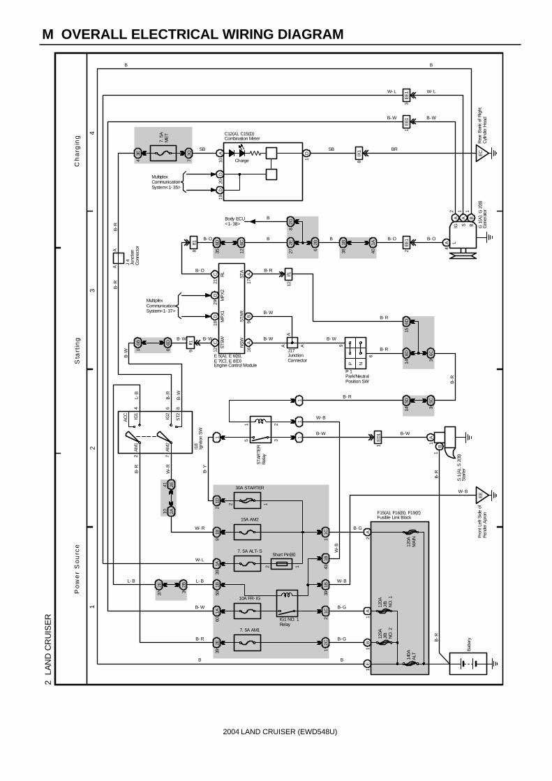
2004 LAND CRUISER (EWD548U)
M OVERALL ELECTRICAL WIRING DIAGRAM
12
34
2 L
AN
D C
RU
ISE
R
140A
ALT
2C
1
7. 5A AM1
2E39
B- G
B
1A60
15A AM2
30A STARTER
1B9
1C
Bat
tery
AM
27
864A
M1
ST2IG2
IG1
AC
C
2
21
35
11
1A
B1E
D1
1
6
SB
9
P N
3E4
7. 5
AM
ET
3Q7
2E27 6
2B 1B38 40
1A
2EE
1
4A L
A2
A B
IG S B
1E
E13
EE
1
Ch
arg
ing
Sta
rtin
gP
ow
er
So
urc
e
B-R
W-R
L-B
B-R
B-W
B-R
B-R
B- W
B- R
B
W- R B- G
B- W
B- R
B- W
B
B B- O
B- W
W- L
B- O
B- W
W- L
B
STAR
TER
Rel
ay
1
11
12
120A
J/B
NO
. 2
120A
J/B
NO
. 1
1E
1B
2A
1A1C
2
B- G
1A39
7. 5A ALT- S
IG1 NO. 1Relay
1B50
10A FR- IG
41 2E10 2A
Short Pin(B)
I18
S 1
( A) ,
S 2
( B)
1B39
1B43
EE
F15(A), F16(B), F19(E)
1
Fron
t Lef
t Sid
e of
Fend
er A
pron
1D2
1
B-Y
2B3
2E37
L- B
W- L
L- B
6D6
6B1
6D14
6C3
6D15
P 1
AA
12C
16A
9B
17A
21C
E 5(A), E 6(B), E 7(C), E 8(D)
6D35
6C12
B- O
B- W
B- W
B- R
B
C12(A), C15(D)
J17
A
B- R
B- W
W- B
B- R
W- B
W-B
G 1
( A) ,
G 2
( B)
STSW
NS
WS
TAR
STA
RL
10A
1D
W- B
5D14
5C3
B-R
AA
J 4
B-R
B-R
120A
MA
IN
12
SB
EC
8IX
1 BR
Charge
Rea
r B
ank
of R
ight
Cyl
inde
r Hea
d
2G8
BBody ECU<1- 38>
Combination Meter
Engine Control Module
Gen
erat
or
Igni
tion
SW
Park/NeutralPosition SW
Sta
rter
JunctionConnector
Junc
tion
Con
nect
or
Fusible Link Block
29D
18D
MultiplexCommunicationSystem<1- 37>
20D
19D
MultiplexCommunicationSystem<1- 35>
MP
X2
MP
X1
B- WB- W
B-W
B- O
9If1
8If1
12If1
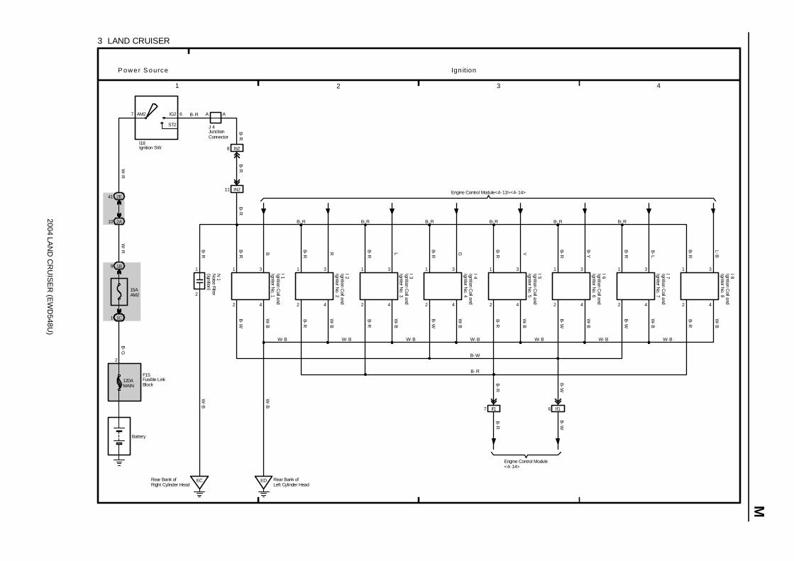
2004 LAN
D C
RU
ISE
R (E
WD
548U)
M
1 2 3 4
3 LAND CRUISER
Battery
15AAM2
1B9
7 IG2
ST2
AM2 6
2 4
1 3
B-R
L-BW
-B
2 4
1 3
B-R
B-L
W-B
2 4
1 3
B-R
B-Y
W-B
2 4
1 3
B-R YW
-B
2 4
1 3
B-R GW
-B
2 4
1 3
B-R LW
-B
2 4
1 3
B-R RW
-B
2 4
1 3
B-R BW
-B
IN211
2
1
EC
Ign itionP ower S ource
B- R
B- R B- R B- R B- R B- R B- R
W- B W- B W- B W- B W- B W- B W- B
B- W
B- R
B-R
B-W
B-W
B-R
B-W
B-R
B-R
B-W
W-B
W-B
B-R
B-R
W-R
W-R
B-G
B-R
B-W
Engine Control Module<4- 14>
Engine Control Module<4- 13><4- 14>
1C1
2E41
2A10
F15
8 Ib2
B-R
ED Rear Bank ofLeft Cylinder Head
Rear Bank ofRight Cylinder Head
7 If1 6 If1
B-R
B-W
N 1
I 1 I 2 I 3 I 4 I 5 I 6 I 7 I 8
I18
A A
J 4
B-R
120AMAIN
Ignition Coil and
Igniter No. 1
Ignition Coil and
Igniter No. 2
Ignition Coil and
Igniter No. 3
Ignition Coil and
Igniter No. 4
Ignition Coil and
Igniter No. 5
Ignition Coil and
Igniter No. 6
Ignition Coil and
Igniter No. 7
Ignition Coil and
Igniter No. 8
Ignition SW
Noise Filter
(Ignition )
JunctionConnector
Fusible LinkBlock
2

2004 LAND CRUISER (EWD548U)
M OVERALL ELECTRICAL WIRING DIAGRAM
12
34
4 L
AN
D C
RU
ISE
R( C
ont.
nex
t pa
ge)
2A
1B
Batte
ry
B- G
B- G
1C1
2C1
15A AM230A BAT
1B24
1B9
10A ETCS
25AEFI OR ECD NO. 1
1B2
1B3
1B11
2D20
A
2A10
2E41
34
213Q51
3Q7
3E8
3B22
3Q52
B C D E F G H
3B25
3Q71
I J
24
13
11
11
5 3
2 1
11
IFS
et B
olt o
fC
owl S
ide
J/B
LHE
EFr
ont L
eft S
ide
ofFe
nder
Apr
on
1A43
1B39
1B44
EFI OR ECD Relay
C/OPN Relay
2A5
10A
EFI
OR
EC
D N
O. 2
2B10
2K16
2Q45
2D34
2D36
11
K QP
ON
ML
Po
we
r S
ou
rce
En
gin
e C
on
tro
l
Short Pin (A)
W- R
L- O
B- W
Y- B
B- R
B- Y
SB
B- R
B- R
SB
SB
L- O
SB
ACC CUT Relay
SB
B-R SB
Y-B
B-R
B-W
B- Y
B- W
B-W B-R
B-R
B-R
B- R
B-Y
B-Y
B- YB- Y
R- L
B- W
W- B
W- B
W- B
B-Y
B-Y SB B-Y
B-Y
B- W
B- Y
SB
B- Y
B- Y
R-L
12
F15(A), F16(B), F17(C)
2 7
AC
C
IG1
IG2
ST2
AM
1
3 6A
M2
I18
1C
7. 5A OBD- 2
2E39 7. 5A AM1
B- W
12
35
EA
Fron
t Rig
ht S
ide
ofFe
nder
Apr
on
ACC Relay
2E40
6B5
6D2 3
IX1
B-R
SB
3Q504
IX1
6B4
6D3
3C1
3E4
7. 5A MET
7. 5A IGN
10A ECU- B2
AA
J 4
AB
-R
B- G
W- R
B- R
SBB
B- RB- R
120AMAIN
140AALT
120AJ/B NO. 3
120AJ/B NO. 2
B-R
B
B- G
Igni
tion
SW
Junction Connector
Fusible Link Block
B
7A6
7A5
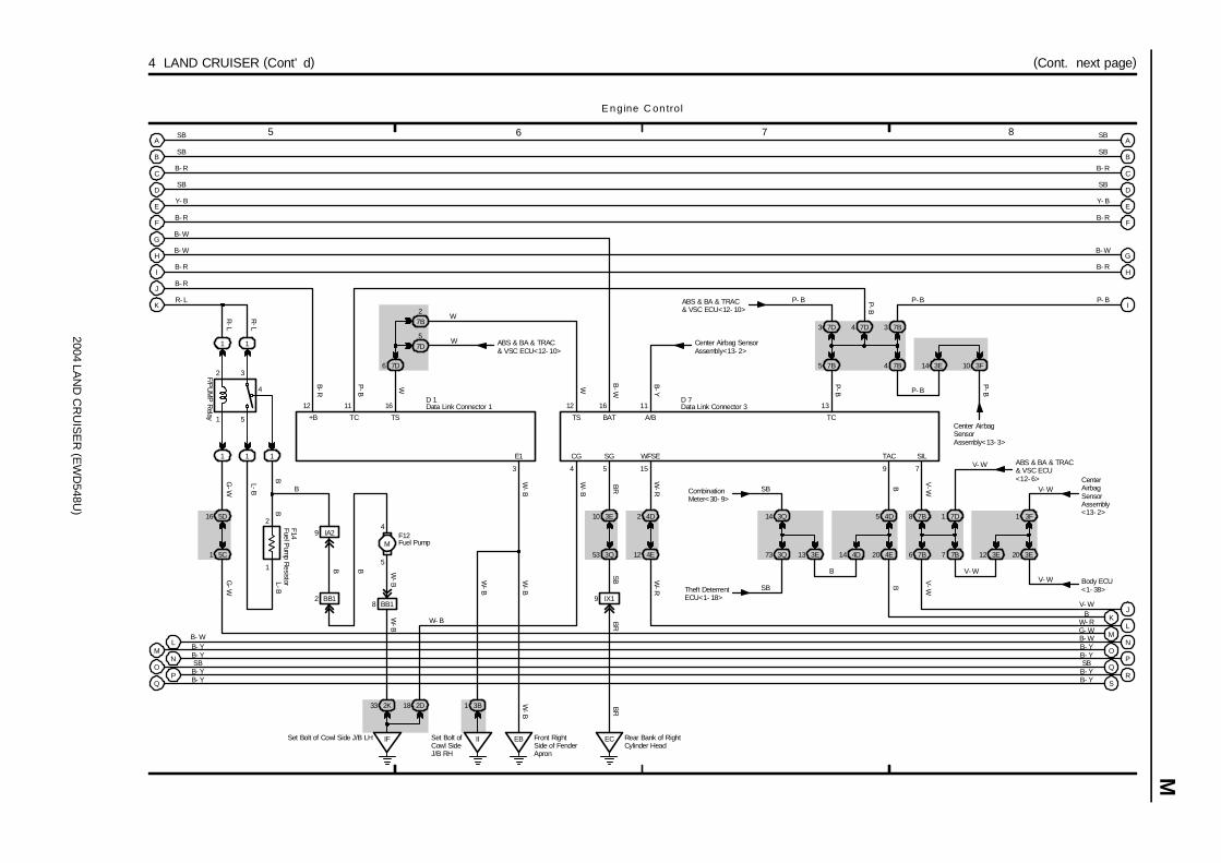
2004 LAN
D C
RU
ISE
R (E
WD
548U)
M
5 6 7 8
4 LAND CRUISER (Cont’ d) (Cont. next page)
A
B
C
D
E
F
G
H
I
J
K
O
Q
LM
P
N
1
2
5
3
4
1 1
1 1 1
1
2
BB
IFSet Bolt of Cowl Side J/B LH
F14 9 IA2
5
4
M
8 BB1
2K33 18 2D
W
16
7D6
27B
57D
W ABS & BA & TRAC& VSC ECU<12- 10>
11 12 16
4 5
EC Rear Bank of RightCylinder Head
EB Front RightSide of FenderApron
IISet Bolt ofCowl SideJ/B RH
3B1
IX19
3Q53
3E10
3
12D 1
15
4E12
4D2
3E13
3Q14
3Q73 4E20
4D5
4D14 7B7
7B8
7B6 3E20
3F1
3E12
CombinationMeter<30- 9>
Theft DeterrentECU<1- 18>
9 7
Body ECU<1- 38>
CenterAirbagSensorAssembly<13- 2>
V- W
11
Center Airbag SensorAssembly<13- 2>
7B5
7D3 7D4 7B3
7B4
ABS & BA & TRAC& VSC ECU<12- 10>
3E14 3F10
Center AirbagSensorAssembly<13- 3>
13D 7
5C1
5D16
F12
B-R
SB
SB
B- R
SB
Y- B
B- R
B- W
B- W
B- R
B- R
R- L
B- WB- YB- YSBB- YB- Y
R-L
R-L
W-B
P-B
+B TC TS
E1
TS BAT
F/PU
MP
Relay
G-W
G-W
L-B
L-B
B B
2 BB1
W-B
W-B
BR
W-B
W-B
W-B
CG
W-B
SB
SG WFSE
W-R
BR
BR
W-R
P- B
W B-W
B-Y
W
A/B
B
TC
P- B
P- B
B
P-B
P-B
P-B
V-W
B
V-W
B
SB
SB
V- W
TAC SIL
V- W
E
D
C
B
A
F
G
H
I
JK
LM
NO
PQ
RS
SB
SB
B- R
SB
Y- B
B- R
B- W
B- R
P- B
V- WB
W- RG- WB- WB- YB- YSB
B- YB- Y
E ngine C on trol
W- B
7D1
ABS & BA & TRAC& VSC ECU<12- 6>
Data Link Connector 1 Data Link Connector 3
Fuel Pump
Fuel Pum
p Resistor
V- W
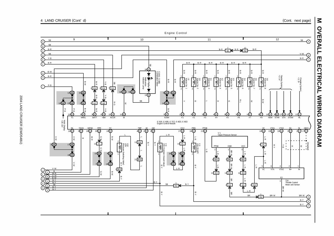
2004 LAN
D C
RU
ISE
R (E
WD
548U)
M O
VE
RA
LL ELE
CT
RIC
AL W
IRIN
G D
IAG
RA
M
9 10 11 12
4 LAND CRUISER (Cont’ d) (Cont. next page)
E
4E21
4D12
5C2
5D15
5 Id1
1 IG1
20 E
4D
1 Id3
2 IG1 7 IX1
18
4E17
8 E 3 E 6 D 15 A
18 E 5 E 19 E A33 10 E
6C7
6D10
5D13
5C4
14
BD31
V10
1Id1
BB17
If14
IX2
Starting System
<2-3>
BB1 4 BB1
10 A
11 B
11 E
4E
E9
2
1
1 A
Y
IN212
I 9
B-R
2
1
6 C
W
I15
B-R
B-R
I14
R-L
B3
1
22
1
5 A
G
I13
B-R
B-R
I12
RA4
1
22
1
3 A
L
I11
B-R
B-R
I10
B
A2
1
2 2
1
5 C
B-W
I16
B-R
1 E 2 E
1
2 13 ID4
4 E
B-Y
B-Y
LL
L
2
1
34 A 21 E
12 ID4
2
14 ID4 11 ID4
5
18 A 21 A
6
R-Y
31 A
4
Y-B
3 C
2
R
2 C
1
W
17 C
3
BR-W
L-R
BR-W
L-BL-B
BR
-W
L-RL-R
BR
BR
L-R
2 1 3
V 1
16 A 9 B
B- R B- R B- R B- R B- R B- R
B- R
C12 (A
), C13 (B
)
B-R
W
B-R
B- R
W IGSW #1 #2 #3 #4 #5 #6 #7 #8 NSW STAR
+B +B2TBP PRG PTNK
3
L-B
L-B
B-Y
PTNK GND VCC
VC VTA VTA2 M+ M-
E2
T16
VC VTA1 VTA2 M+ M- GE01
(Shielded )
B- R
SB
BR- W
9
L-RL-R
17 A
STA
27 A
CCV
6C8
6D9
5C7
5D10
V 9
1
2
V 4
Id11 IN23
1IN2
L-R
4D 4A132 2D 78 2Q
Ib27
12 C
STSW
V-W
SIL
Y-B
V-W
V-W
B
TACH WFSE FPR FC
W-R
G-W
G-W
B-W
B-W
P-B
B-W
B-R
SB
Y-B
B-RB
-R
Y-B
SB
R-G
B-W
P- B
TC MREL BATT +BM ACCR
B-R
SB
B-YB
-Y
L
B- Y
L- R
B- Y
B-YB
-Y
B-Y
L-R
L- R
L- R
BR BR- W
D
C
B
A
F
G
H
I
JK
LM
NO
PQ
RS
4A3
SB
SB
B- R
SB
Y- B
B- R
B- W
B- R
BV- W
W- RG- WB- WB- YB- YSBB- YB- Y
A
B
C
D
E
F
SB
V- W
B- R
E 5(A), E 6(B), E 7(C), E 8(D), E 9(E)
B- Y
B- Y
E ngine C on trol
Malfunction
Indicator Lamp
21 BD3
4E10
P-B
Multi-D
isplay<
26-15>
21 C
RL
Charging S
ystem<
2-3>
Com
bination Meter
Engine Control Module
Injector No. 1
Injector No. 2
Injector No. 3
Injector No. 4
Injector No. 5
Injector No. 6
Injector No. 7
Injector No. 8
Vapor Pressure SensorV
SV (E
VAP
)
VSV
(Canister C
losed Valve )
Throttle ControlMotor and Sensor
VSV
(Pressure S
witching V
alve )
G-W
L-R
14 If113 If1

2004 LAN
D C
RU
ISE
R (E
WD
548U)
M
13 14 15 16
4 LAND CRUISER (Cont’ d) (Cont. next page)
19 A 30 A 29 A 20 A
5 4 2
3
1
A28
G-B
L-Y
G-W
Y-B
BR
-W
BR- WBR- W
BR-W
B-Y
BR-W
THW VG E2G THA E2
VG E2G THA
+B
E2
BR- W
1
2
Y-B
G-W
L-Y
8 IN2 2 IN2 10 IN2
6 IW3 5 IW3 8 IW3
Y-B
G-W
L-Y
7 IW3 7 IN2
3 If1
M 1
9H
8
EB3
1
B- Y
33 B 22 B
1 3
2 4
HT2A OX2A
HT OX
+B E1
Y W
B-Y
23 B 4 B
3 1
2 4
OX1A HT1A
OX HT
+B E1
B R
B-Y
BR-W
H 5
25 B 21 B
1 3
2 4
HT2B OX2B
HT OX
+B E1
R-B
W
B-Y
BR-W
29 B 5 B
3 1
2 4
OX1B HT1B
OX HT
+B E1
B LBR
-W
H 6
EC
EB3
BR- W
B- Y
BR- WBR- W
9 A
IGT1
B
8 A
IGT2
R
25 A
IGT3
L
11 A
IGT4
G
12 A
IGT5
Y
26 A
IGT6
B-Y
13 A
IGT7
B-L
BR-W
12 E
ELS
2 D
ACMG
13 E
ELS2
33 D
ACLD
32 D
THE LCKI
C2331 D
A/CSTHWO
D14
Air Conditioning (Front) System<31- 6><31- 7>
Ignition Coil and Igniters<3- 2><3- 3><3- 4>
VPA
E22
VPA2
E23
EPA
E28
H 7
VCPA
E26
3 EB3
EPA2
E29
EB38
VCP2
E27
5 2 3 6 1 4
R R-B
BR
-W
L-R
W-R
WA14
EB35
(Shielded )
(Shielded )
(Shielded )
BR
Rear Bank ofRight CylinderHead
10 A
IGT8
L-B
24 A
IGF1
B-W
23 A
IGF2
B-R
EB311
17 D
V
14 E
BC
enter Airbag Sensor
Assem
bly<13-8>
19 D
G-W
Stop Light S
W<
10-3>
SPD F/PS
Com
bination Meter
<30-6>
STP
B- Y
BR
BR
BR-W
B- Y B- Y
BR- W
R-B
W
B L
B
A
C
D
E
F
B- R
SB
V- W
BR- W
B- Y
B- Y
E ngine C on trol
E 2
A
B
C
F
G
SB
V- W
B- R
(Shielded)
E 5(A), E 6(B), E 7(C), E 8(D), E 9(E)
D
E
(Shielded)
(Shielded)
B-Y
(Shielded )
(Shielded )
BR
(Shielded )
D
D D
BR BR
EB19
BR
BR
CC
C C C E E E E
J17
(Shielded )E
(Shielded )
(Shielded )
(Shielded)
(Shielded)
VPA1 VPA2 EP1 VCP1 EP2 VCP2
G-W
Body E
CU
<1-39>
Accel Position Sensor
Engine C
oolantTem
p. Sensor
Engine Control Module
Heated O
xygen Sensor
(Bank 1 S
ensor 1 )
Heated O
xygen Sensor
(Bank 1 S
ensor 2 )
Heated O
xygen Sensor
(Bank 2 S
ensor 1 )
Heated O
xygen Sensor
(Bank 2 S
ensor 2 )
Mass Air Flow Meter
Junction Connector
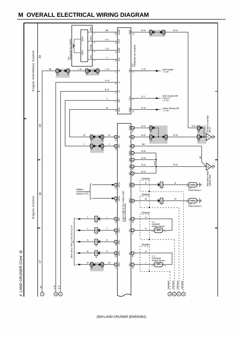
2004 LAND CRUISER (EWD548U)
M OVERALL ELECTRICAL WIRING DIAGRAM
1718
19
20
4 L
AN
D C
RU
ISE
R (
Con
t’d)
2B
KNK
2
1B
KN
K1
11
B
2
(Shielded)
(Shielded)
EC
1
K 1
K 23
W
EC
1
5
EC
6
Rea
r Ba
nk o
f Rig
htC
ylin
der H
ead
A6
7A
7C
C4
1C
BR
W- B
W- B
W- B
W- B
4D81
D IFSe
t Bol
t of C
owl S
ide
J/B
LH
7
15E
10
R- B
4
R- Y
22
3P2
3P1
2E
14
W- B W- B
14
57
T10
811
1213
Y
L- B
V- G
BR
29
1
IGD
+BVC
5C
OD
ETX
CT
AG
ND
4C 2D
KSW
CTY
GN
D
W- B
W- B
B- R
Door Courtesy SWFront LH<1- 31>
Unlock Warning SW<1- 19>
V- W
L- W
18
E01
E02
E03
ME0
1E1
HP
EO
M
2Q22
2E19
4A9
4A2
SB L- W
17E
W
AB
S &
BA
& T
RA
C &
VS
C E
CU
<12
-6>
24E
R
30E
G
25E
Y
31E
L
11
NE
OE
NG
+E
NG
-TR
C+
TRC
-
5D 5C
12
12IG
413
IG4
1IG
42
IG4
W
R
G
Y
L
MultiplexCommunicationSystem<1- 37>
18D
29D
MP
X1M
PX2
16 26D IMO
3P 3M
6
Y
15 27D IM
I
3P 3M
5
W
4E22
EFIO
EFII
W
Y
W
Y
W
W- B
BR
B
W- B
W-B
3IND G- R
W- B
T19
A B C
SB
V-W B-R
( Shi
elde
d)
( Shi
elde
d)F G
En
gin
e C
on
tro
lE
ng
ine
Im
mo
bili
se
r S
ys
tem
E 5(
A) ,
E 6
( B) ,
E 7
( C) ,
E 8(
D) ,
E 9
( E)
25CNE
+ L
24CNE
- G
R
32CG2-
G
C 3
C 1
(Shielded)
22
11G
2+ C27
( Shi
elde
d)
( Shi
elde
d)D E
(Shielded)
VC
5C
OD
ETX
CT
GN
D
AN
T1AN
T2
Multi- Display<1- 18>
CamshaftPosition Sensor
CrankshaftPosition Sensor
Engi
ne C
ontro
l Mod
ule
Knock Sensor 1
Knock Sensor 2
Tran
spon
der K
ey A
mpl
ifier
Tran
spon
der K
ey C
ompu
ter

2004 LAND CRUISER (EWD548U)
Memo

2004 LAND CRUISER (EWD548U)
M OVERALL ELECTRICAL WIRING DIAGRAM
12
34
5 L
AN
D C
RU
ISE
R( C
ont.
nex
t pa
ge)
30A
BAT
1B24
1B9
15A
AM
2
1C1
2E41
2A10
2A
1C
1B
7. 5
AAM
1
2C1
2E39
12
53
IFS
et B
olt o
fC
owl S
ide
J/B
LH
10A
GAU
GE1
2Q65
2E37
2Q77
2 7
AC
C
IG1
IG2
ST2
AM
14 6
AM
2
AA 3E4
12
35
3Q39
3C1
10A GAUGE2
7. 5A MET
3E3
3Q7
IIS
et B
olt o
fC
owl S
ide
J/B
RH
Shor
tPi
n( A
)
Batte
ry
B- G
B- G
B- G
L- O
W- RW- R
L- B
SB
B- R
I18
B- R
IG1 NO. 3Relay
SB
B- G
B-R
W-R
IG1
NO
. 2R
elay
10A ETCS
25AEFI ORECD NO. 1
1B2
1B11
1B3
24
15
11
11
1B39
1A43
1B44
EE
Fron
t Lef
t Sid
e of
Fend
er A
pron
EA
Fron
t Rig
ht S
ide
ofFe
nder
Apr
on
2A5
2D34
I JA B C D E F G
5C2
5D15
7. 5A IGN
3E8
H
R- L
SB
B- R
B- W
B- Y
B- W W- B W- B
W- B
B- Y
B- R
Y- B
L-O
B-R Y-B
SB
R-L SB
B-R
B-W
120A
MA
IN14
0AAL
T
120A
J/B
NO
. 3
120A
J/B
NO
. 2
B- R
EFI
OR
EC
DR
elay
SB
L- B
B-Y
B-Y
Po
we
r S
ou
rce
J 4
F15(
A), F
16( B
) , F1
7(C
)
B-Y
2 1
Igni
tion
SW
JunctionConnector
Fusi
ble
Link
Blo
ck
2D36
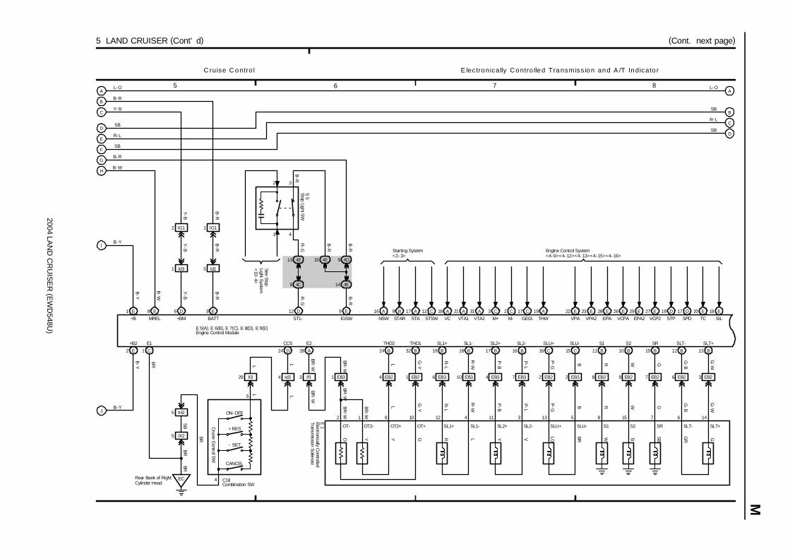
2004 LAN
D C
RU
ISE
R (E
WD
548U)
M
5 6 7 8
5 LAND CRUISER (Cont’ d) (Cont. next page)
G
F
E
D
C
B
A
J
I
H
L- O
B- R
Y- B
SB
R- L
SB
B- R
B- W
B- Y
B- Y
2 E
8 E 6 D 3 E
1 Id3 5 Id1
2 IG1 1 IG1
12 D
4C9
4E13 4E15 4D9
9 E A18 A21 A31 C3 C2 C17 E22 E23 E28 E26 E29 E27
VC VTA1 VTA2 M+ M- GE01 VPA VPA2 EPA VCPA EPA2 VCP2
Engine Control System<4- 9><4- 12><4- 13><4- 15><4- 16>
Y-B
B-W
B-RB
-R
Y-B
R-G
Y-B
B-R
MREL +BM BATT ST1-
B-R
B-R
IGSW
C ruise C ontro l E lec tronically Contro lled Transmiss ion and A /T Indicato r
+B2
28 A
3 If1
2 1
19 B
6 EB3
12
R-L
R-L
BR-W
BR-W
BR
-W
BR
-W
18 B
10 EB3
4
R-W
R-W
17 B
4 EB3
11
P-B
P-B
16 B
7 EB3
3
P-L
P-L
16 C
2 EB2
13
P-G
P-G
15 C
2 EB3
5
BB
11 B
8 EB2
8
RR
10 B
9 EB2
15
WW
E2 SL1+ SL1- SL2+ SL2- SLU+ SLU- S1 S2
A
B
C
D
4E14
L- O
SB
R- L
SB
B-R
B-Y
B-Y
15 B
7 EB2
7
GG
12 B
6 EB2
6
G-B
G-B
13 B
3 EB2
14
G-W
G-W
24 B
4 EB2
9
LL
32 B
1 EB2
10
G-Y
G-Y
SR SLT- SLT+THO2 THO1
OT+OT2+ SLT+SLT-SRS2S1SLU-SLU+SL2-SL2+SL1-SL1+OT2-OT-
O Y R L Y V LG BR W B SB
GR GY O
E 1
D19 D17 E20 E18
STP SPD TC SIL
A19
THW
R-G
A16 B9 A17 C12
NSW STSWSTASTAR
Starting System<2- 3>
Electronically Controlled
Transmission S
olenoid
1 C
E1
ECRear Bank of RightCylinder Head
4 Id3
D24
CCS
5 IX2
5 IH2
SB
BR
BR
E 5(A), E 6(B), E 7(C), E 8(D), E 9(E)Engine Control Module
LLBR
CANCEL
- SET
+ RES
ON- OFF
5
4
BR
C18Combination SW
29 II3
LL
1 EB3
BR-W
BR-W
1 E
+B
2 3
1 4
Stop Light S
WS
5
See Stop
Light System
<10-4>
B-R
Cruise C
ontrol SW
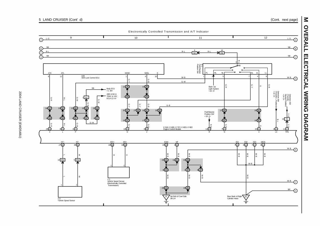
2004 LAN
D C
RU
ISE
R (E
WD
548U)
M O
VE
RA
LL ELE
CT
RIC
AL W
IRIN
G D
IAG
RA
M
9 10 11 12
5 LAND CRUISER (Cont’ d) (Cont. next page)
6
27 B
10 EB2
1
LL
35 B
5 EB2
2
WW
26 B 34 B
1 2
T17
V 3
Set Bolt of Cowl SideJ/B LH
IF
15 E
4E22
4D8
4C11
1 D
2D22 2E18
3M10
3P1 3P8
A
B
C
D
23 D 8 D
3P14
3M6
128
IX11
5C
11 5D3P13 6D13
3M2 6C4
6 E
6D12
6C5
3P12
3M1
6C20
6C19
6D27 6C16
6C17
6D30
10 D 9 D
3P10
3M3
11 D
7
20 D
6D28
6C18
8
7 A 6 A 7 C 4 C
ECRear Bank of RightCylinder Head
L- O
SB
R- L
SB
E 5(A), E 6(B), E 7(C), E 8(D), E 9(E)
NT+ NT-
R G
SP2+ SP2-
W-B
W-B
W-B
W-B
W-B
EOM HP
W-B
E01 E02 E03 ME01
W-B
W-B
W-B
W-B
W- B
A
B
C
D
E
F
G
L- O
SB
SB
W- B
W- B
W- B
BR
1 6 21
4 D
G-R
R-L
G-W
G-W
G-W
G-W
R-L
G-R
G- W
4 L P
SB
AT4
Body ECU<1- 38>
ABS & BA &TRAC & VSCECU<12- 6>
10
ATL NSSD NSSL
A48
G
B-L
3R
5
P 1
L4
W- B
E lectronically Contro lled Transmiss ion and A /T Indicato r
G-Y
G-B
G-B
G-Y
G-Y
G-Y
G-B
G- B
D 2
W-B
3
7 E
6D17
6C1
G-R
N
PL RL NL 2L LLDL
4
G-R
G-Y
G G-B
E
RB
Detection SW
(Transfer L Position )
<14-3>
Ib26
IN214
R- LR- L
R-L
Engine Control Module
Park/N
eutralP
osition SW
Vehicle Speed Sensor(Electronically Controlled Transmission)
Shift Lock Control ECU
Turbine Speed Sensor
Detection S
W(TransferN
eutral Position )
<14-3>
11 C
Y-G
TFN
G- W
Park/NeutralPosition SW<10- 2>
Back- UpLight System<10- 2>
R-B
Y-G
10 If1
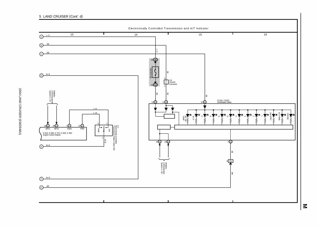
2004 LAN
D C
RU
ISE
R (E
WD
548U)
M
13 14 15 16
5 LAND CRUISER (Cont’ d)
5 228 D5 D
P R N D 4 3 2 L
2nd STR
T
EC
T PWR
10 A
1 D
8 IX1
10A EC
U-B
2
3B25
3Q44
12 D
A
AJ14
11 D
A
B
C
D
E
F
G
L- O
SB
SB
W- B
W- B
W- B
BR
E 5(A), E 6(B), E 7(C), E 8(D), E 9(E)
3
L- R
L- W
SNWI PWR
SB
SB SB
SB
L-O
SBBR
C12(A), C15(D)
W-B
E lectron ically Controlled Transmiss ion and A /T Ind icato r
2nd
PW
R
E 4
Combination Meter
Electronically Controlled
Transmission P
attern Select S
W
Engine Control Module
JunctionConnector
CR
UIS
E
A/T P
A/T O
ILTEM
P
Multiplex
Com
munication
System
<1-37>
29 D18 D
MPX1 MPX2
Multiplex
Com
munication
System
<1-35>
19 D 20 D

2004 LAND CRUISER (EWD548U)
M OVERALL ELECTRICAL WIRING DIAGRAM
12
34
6 L
AN
D C
RU
ISE
R
Bat
tery
120A
MA
IN
2C1
7. 5A AM1
2E39
1C1
15A HAZ- TRN
1B65
1
4
78 5 6 2
W- B
1A43
1A37
1A47
1B37
34 BM2K
40
2E5
2Q39
3
34 BKFr
ont S
ide
Und
er th
e Fr
ont
Pas
seng
er’
s Se
at
3K6
3Q3
3E31
SB
4E
A2
EA
Fron
t Rig
htS
ide
ofFe
nder
Apr
on
LH RH
2
Po
we
r S
ou
rce
Tu
rn S
ign
al
an
d H
az
ard
Wa
rnin
g L
igh
t
W- BW- B
W- BSB
G- B
B- R
G- W
B- G
B- G
G- B
G- B G- B
G-W
G-Y
G-Y
G-BW W-B
G- Y
G- Y
G- Y
G- Y W- B
G- Y
G- B
G- Y
G- B
W
W
W- B
1B39
EE
Fron
t Lef
tS
ide
ofFe
nder
Apr
on
TRTB
TL
3II3
W- B
23
23
* 1
: w/ N
avig
atio
n Sy
stem
* 2
: w/o
Nav
igat
ion
Sys
tem
24A
12C
120A
J/B
NO
. 2
140A
ALT
F15(A), F16(B), F17(C)
1B
2A
3E36
3D25
C16
AAA
A
3A12
Short Pin(B)
G-Y
W- B
31
IF2D2
Set B
olt
of C
owl
Side
J/B
LH
G- Y
W- B
W- B
J11
F 4
R13
R10
Turn
Turn
T11
A
W- B
W- B
J 3
G- B
G-B
3N7
3P1
2E18
W- B(*1)
(*2)
W(*1)
(*2) (*2)
3 16
W- B(*1)
C28
HZR
GN
D
12
2II3
1II3
Towing ConverterRelay<7- 3>
SB
SB
SB
8IX
1
EC
BR
4A
6A
1D
Rea
r Ban
kof
Rig
htC
ylin
der
Hea
d
C12(A), C15(D)
Left
Rea
rSi
de Q
uarte
rPa
nel
2A13
F 3
LL
+B
GN
D
EH
W EL ER LR
2
AC
C
IG1
AM
14
2B15
2E2
I18
IG
B-W
3C1
3Q39
3E32
II
1C
B- G 120A
J/B
NO
. 3
10A ECU- IG2
IG1 NO. 3 Relay
SB
2Q77
2E37
B- W
Turn SW
12
53
Set B
olt o
fC
owl S
ide
J/B
RH
3E35
B- G
W- B
B-W
Combination Meter
Com
bina
tion
SW
Front Turn SignalLight LH
Front Turn SignalLight RH
Igni
tion
SW
Rear CombinationLight LH
Rear CombinationLight RH
Turn
Sig
nal F
lash
er
Junction Connector
Junc
tion
Con
nect
or
Center ClusterIntegration Panel
Fusible Link Block
Turn RH
Turn LH
GN
D
A/C ControlAssembly
A45(A), A47(C)
HZD

2004 LAN
D C
RU
ISE
R (E
WD
548U)
M
1 2 3 4
7 LAND CRUISER
1C2
15A TAIL
1B49 58 1B
2
ACC
IG1AM1
1
2
5
3
30A BA
TT CH
ARG
E
2K52E39
7. 5A AM
1
2C1
IFSet Bolt of Cowl SideJ/B LH
1 A 1 B
B-G
B-G
G B-R B
I18
F15(A), F16(B)
120AJ/B NO. 1
140AALT
120AJ/B NO. 2
Battery
TaillightSystem<8- 1>
TAILRelay
IG1 N
O. 2
Relay
T railer Tow ing
30A TO
WIN
G
30A TO
WIN
G B
RK
1B721B61
30A TO
WIN
G TAIL
1B69
2E37
4
2A8
2E6
2 2A
2E4
17 IA2
11 BD2
3 BX110 BD2
BJ Under the Driver’ sSeat
BKFront Side Under theFront Passenger’ s Seat
1 ID4
17 BD2
5 BX1
6A12
6C11
1 IA2
8 BD2
2 BX1
W B G
15 BD2
8 BX1
7 BX1 1 BX1 4 BX1
1 BL5
Turn Signal
Flasher
<6-2>
L- B
L GG B
B
G-B
G-Y
1 93
4 2
2 1 3 5 7 6
5 2
1 4
4Y B G R BR
LW
-L
W W-B
W-B
W- B
G-Y
G-B
W-L
G-W
B G
T15
G W
G W
IISet Bolt ofCowl SideJ/B RH
3E34
3
Park/Neutral
Position SW
<10-2>
R-B
Stop Light SW
<10-3>
W-B
W-B
TAIL +B
STOPBRK
BG
L
T12
G-W
Stop Light SW
<10-3>
9 BD2
P ower S ource
GND
G-W
8
6 BD2
G-W
6
W-B
W-B
G-B
G-Y
Ignition SW
Trailer Socket
Towing C
onverter Relay
Fusible Link Block
BM Left Rear SideQuarter Panel
W-B
W-B
12 BL1
W- B
W-B
Towing BrakeController
T18
1
2
3
5
Towing H
itchR
elay
T23
E
E
B
B B
W-B
JunctionC
onnector
J22
W-B
W- B W- B
W-B
W- L
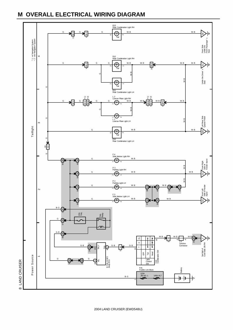
2004 LAND CRUISER (EWD548U)
M OVERALL ELECTRICAL WIRING DIAGRAM
12
34
8 L
AN
D C
RU
ISE
R
Bat
tery
140A ALT120AJ/B NO. 1
1
B- G
15A
TAIL
8C
LightControlSW
14
16
Hea
d
H
Tai
l
OFF
TE
L IIS
et B
olt o
fC
owl S
ide
J/B
RH
3E353
II3 A A
W- BW- BW- B
Fron
t Lef
tS
ide
of F
ende
rA
pron
1B40
1A36
121A59
1B60
1A50
EA
Fron
t Rig
htS
ide
ofFe
nder
Apr
on
12
7BP
4
BP3
6
21
21
G G W- B
8B
Q2
10B
Q2
6 3 BK
Fron
t Sid
eU
nder
the
Fron
t Pas
seng
er’
sSe
at
6B
L3
G- B
W- BG
G
G
W- B
W- B
W- B
W- B
G
W-B
G
G G G
22
TAIL
W-B
W- B W- B
11
W- BW- BGGP
ow
er
So
urc
eT
aill
igh
t
1B39
EEW- B
36 BM
Left
Rea
r Si
deQ
uarte
r Pan
el
W- B
G- B
W-B
21
G W- B
21
G W- B
1A37
5II5
1B67
1B49
5D3
5B4
2B24
IDL
28A
TAIL
Rel
ay
F15
J 3
C16
B 7
( A) ,
B 9
( C)
G
G- B
1A58
1A49
F 3
P 2
P 3
F 4
Tail
1A30
1B35
W-B
W- B
W- B
BJ
Und
er th
e D
river
’s
Sea
t
W-B
W- B
W-B
GG
GG
13BD
2
W- BW- BG G
G
Tail
Tail
Tail
R13
R12
L 2
R11
L 1
R10
18 TRLY
21C
G- B
G
B- G
G
Com
bina
tion
SW
Side Marker Light LH
Side Marker Light RH
License Plate Light LH
License Plate Light RH
Parking Light LH
Parking Light RH
Rear Combination Light LH
Rear Combination Light LH
Rear Combination Light RH
Rear Combination Light RH
Bod
y E
CU
JunctionConnector
Fusible Link Block
IA2
10
3B
H2
BH
14
( *1)
( *2)
5B
H2
BH
23
( *1)
( *2)
* 1
: w/ N
avig
atio
n S
yste
m*
2 : w
/o N
avig
atio
n S
yste
m

2004 LAND CRUISER (EWD548U)
Memo

2004 LAND CRUISER (EWD548U)
M OVERALL ELECTRICAL WIRING DIAGRAM
12
34
9 L
AN
D C
RU
ISE
R( C
ont.
nex
t pa
ge)
1C2
7. 5
APA
NEL
1B49
1B63
2
AC
C
IG1
AM
1
12
532Q65
2E39
7. 5
AA
M1
2C1
IFS
et B
olt o
f Cow
l Sid
eJ/
B L
H
1A
1B
B- G
B- G
G
B- R
SB
Po
we
r S
ou
rce
Illu
min
ati
on
1IF
1
4IF
111
IF2
5IF
18
IF2
AA
6IF
2
21
21
21
65
IF21
A B D E
14
52
63
B
W- B
W- G
W- R
SB
SB
SB
SB
SBW- G
W- G
W- G
W- G
G
G
G
G
W-G
G W- G
G
R- LSB
GS
BG SB
SB
CS
B
A
SB
R 6
J 6
I18
F15(
A) ,
F16(
B)
R40
P 6
P 7
R 5
120A
J/B
NO
. 1
140A
ALT
Batte
ry
B-R
TaillightSystem<8- 1>
TAIL
Rel
ay
IG1 No. 2Relay
IG TCE
TRIL
L-
SB
T
120A
J/B
NO
. 2
Body ECU<1- 38>
Igni
tion
SW
Power QuarterWindow SW LH
Power QuarterWindow SW RH
Remote ControlMirror SW
Rhe
osta
t
Fusi
ble
Link
Blo
ck
Junc
tion
Con
nect
or
Roll Sensing of CurtainShield Airbags Cutoff SW
10A
GA
UG
E1
2E37
4L-
B
AA
SB
Junc
tion
Con
nect
or
J14
L- B

2004 LAN
D C
RU
ISE
R (E
WD
548U)
M
5 6 7 8
9 LAND CRUISER (Cont’ d)
A
B
D
E
SB
G
SB
SB
CSB
A
2B11 2D15
2Q83 2Q55
E
E
3Q68
3K20
1 IQ1
A
A A
1
2
2 IQ1
IFSet Bolt ofCowl Side J/B LH
2Q43
Illumina tion
2 IH2
5 IH2
5 IX2
1
10
4
F
F
J 7
A32
G 3
C13 (B
), C15 (D
)
C18
J23
G A
G B G B
5
4
M 9
4E9
4A13
4D4
4A14 4D3 4D13
4E8
4F1
SB
8 B
7 D
10
19
A47
4F6
1
2
4A11
2
1
4C13
4D7 4D16 4C14
1
6
4B4
D A
E B E B
2
1
2
1
E B E B
D A
4B5
7
14
J20(A), J21(B)
J18(A), J19(B)
C11
A29
E 4
S 3
S 4
J 9(A), J10(B)
G G G G G
GG G
W-G
W-G
G GW
-G
W-G
W-G
W-G
W-G
W-G
W-G
GS
BB
RS
BB
R
W-B
GS
BSB
SB
SBSB
SB
SB
SB SB
G G
GW
-G
A48
W-G
G
ILL+
ILL-
13 IU1
SB
BKFront Side Under theFront Passenger’ s Seat
A A
A
W-B
W-B
22
1
2
M 5
12
2
R36
A
3D35
G
4
17
C28
G
W-G
G
4C7
4C6
GW
-G(*1 )
(*2 )(*2 )
(*1 )
* 1 : w/ Navigation System* 2 : w/o Navigation System
Ashtray Illum
ination
A/C
Amplifier
(Rear )
Cigarette Lighter Illum
inationCom
bination Meter
Com
bination SW
Electronically C
ontrolledTransm
ission Pattern S
elect SW
Glove B
ox Light
Multi-D
isplay
Multi-D
isplay
Radio and P
layer
Seat H
eater SW
(Driver’
s Seat )
Seat H
eater SW
(Front Passenger’
s Seat )
A/C
Control A
ssembly
A/T Shift Lever
Illumination
Junction Connector
JunctionConnector
JunctionConnector
Center C
lusterIntegration Panel
JunctionC
onnector
JunctionConnector
J 7JunctionC
onnector
O 5
Overhead J/B
2L5
G
16
1
GILL
GND
142L
W-B
A
SB
II Set Bolt ofCowl Side J/B RH
3Q58
EC Rear Bank ofRight CylinderHead
JunctionConnector
J12
ILL+
ILL-

2004 LAND CRUISER (EWD548U)
M OVERALL ELECTRICAL WIRING DIAGRAM
12
34
10
LAN
D C
RU
ISE
R
2
AC
C
IG1
AM1
2C1
2D31
1B
1C
15A STOP
120A J/B NO. 3
120A J/B NO. 2
140A ALT
IIS
et B
olt o
fC
owl S
ide
J/B
RH
F16(B), F17(C)
B- G
B- G
I18
Bat
tery
IG1 NO. 3 Relay
12
35
3Q39
3C1
2E37
2Q77
4
SB
10A GAUGE2
3E3
7. 5A AM1
2E39
B- R
B- G
Po
we
r S
ou
rce
Ba
ck
-U
p L
igh
tS
top
Lig
ht
14IN
2
3
4IN
2
12B
D2
35
35
BK
Fron
t Sid
eU
nder
the
Fron
tPa
ssen
ger’
s S
eat
BM
Left
Rea
r Sid
eQ
uarte
r Pan
el
6BP
3
8BP
32 1
R-B
R- L
R- B
G- WG- WG- WG- WG- R
W- B W- B
W- B
W- B W- B
W- BG- W
2 BK
Fron
t Sid
eU
nder
the
Fron
tP
asse
nger
’s
Sea
t
32 BM
Left
Rea
rS
ide
Qua
rter
Pan
el
R- B
R- B R- B
R-B
W- B
W- B
W- B
W- B
G- W
G- W
W- B
G- W
13
13
12
2B
H2
BQ2
3
W- BG- W G- W
BQ2
10
W- B
R- L
2E38
2K39
R- B
R- B
Trai
ler
Soc
ket
<7-
2>6
BL1
R- B
Back- Up
Back- Up
Stop
Stop
BJU
nder
the
Driv
er’
sSe
at
W- B
R10
R13
R11
R12
Stop
Stop
R10
H11 BJU
nder
the
Driv
er’
sSe
at
R- B
R- B
W- B
8B
L4
7BD
2G- W G- W
Towing ConverterRelay<7- 3>
G-W
G-W
G-W
2K35
2E26
3M4
3P11
3M14
3M5
2D35
Navigation ECU<26- 18>
R- B
Eng
ine
Con
trol
Mod
ule<
4-16
>
Tow
ing
Bra
keC
ontro
ller<
7-4>
Shift
Loc
k C
ontro
lEC
U<
24-3
>
G-W
G-W
G-W
S 5
W-B
W- B
G-W
BJU
nder
the
Driv
er’
sS
eat
L- B
G- R
G- W
Ib2
4
R- B
W- B
G- W
2B23
ABS
& B
A &
TR
AC
& V
SC
EC
U<
12-6
>
High MountedStop Light
Igni
tion
SW
Rear Combination Light LH
Rear Combination Light LH
Rear Combination Light LH
Rear Combination Light RH
Rear Combination Light RH
Sto
p Li
ght S
W
Fusible Link Block
R- B
6D
R- B
34
6C13
If11
R- B
R- B R- B
Engi
ne C
ontro
lM
odul
e<5-
11>R
-B
STPI
Bod
y E
CU
3
2
3
R
Rear Combination Light RHR13
6Ib
2
R-L
Park/Neutral Position SWP 1
G- W
R- BTelevision CameraECU<26- 14>
5B
H2
BH
23
( *1)
( *2)
* 1
: w/ N
avig
atio
n S
yste
m*
2 : w
/o N
avig
atio
n S
yste
m

2004 LAN
D C
RU
ISE
R (E
WD
548U)
M
1 2 3 4
4AM1 IG12
11 LAND CRUISER
15A M
IR H
TR
66 1B 1B48
2A6
2J2 2G12
14 IY2
12
5
12
5
9 3I
IFSet Bolt of CowlSide J/B LH
2I8
2K31
2 BP4
1 B
1 A
BMLeft Rear SideQuarter Panel
2D24
SB
A
A
1 IF1
R-L
R-L
IF Set Bolt ofCowl Side J/B LH
2Q43
4
5 6
15 IF1 16 IF1
2Q60 2Q59
2K37 2K36
4 BP4 5 BP4
M1 2
3 6 5
13 IF1 14 IF1
3Q47 3Q48
3K36 3K40
2 BI1 1 BI1
M1 2
3
11 IF2
A
A
P ow er S ource R ear W indow D efogger P ow er R ear Q uarte r W indow
Battery
MIR HTRRelay
B- R
R-W
R-W
R-W
R
R-W
W-B
W-B
LG
SB
BB
BW
-BW
-BW
-B
4
W-B
R P Y-R Y
W-B
SB
W-B
R
SBSB
Y-RP
R P Y-R
SB SBY
Y
SB
R- L
ACC
Open
Close
OPEN ECLS
B
Close
Open
E
B
CLSOPEN
B-G
140A ALT
120AJ/B
NO
. 2
120AJ/B
NO
. 1
F15 (A ), F16 (B )
1C2
1 B 1 A
20A D
EFOG
2C1
7. 5A AM
1
2E39
1B50
2
1
3
5
2E37
2B3
II Set Bolt of CowlSide J/B RH
1
2
3
5DE
FOG
Relay
4
10A G
AUG
E1
2Q65
IG1 N
O. 2
Relay
5D20
5A3
R
B-G
A/C ControlAssembly<31- 14>
L- B
LG
L- B B-R
B-G
SB
R-W
R32
R33
R28 (A
), R29 (B )
P 6 P 7
J12
P10 P11
J14
I18
M irro r H eate r
Ignition SW
Power QuarterWindow SW LH
Power QuarterWindow SW RH
Power Vent WindowMotor LH
Power Vent WindowMotor RH
Rear W
indowD
efogger
Rem
ote Control
Mirror LH
Rem
ote Control
Mirror R
H
Fusible Link Block
JunctionConnector
JunctionConnector
1 BH2
BH24 (*1)
(*2)
5 BH2
BH23
6 BH3
(*1)
(*2)* 1 : w/ Navigation System* 2 : w/o Navigation System

2004 LAND CRUISER (EWD548U)
M OVERALL ELECTRICAL WIRING DIAGRAM
12
34
12
LAN
D C
RU
ISE
R( C
ont.
nex
t pa
ge)
30A
BAT
1B24
1B9
15A
AM
2
1C1
2E41
2A10
2A
1B
7. 5
AA
M1
2C1
2E39
12
53
IFSe
t Bol
t of C
owl S
ide
J/B
LH
10A
EC
U-I
G1
2B18
2E37
2 7
AC
C
IG1
IG2
ST2
AM
14 6
AM
2
AA 3E4
7. 5A MET
3Q7
Shor
tPi
n ( A
)
Bat
tery
B- G
B- G
L- O
W- RW- R
B- R
I18
B- R
B-R
W-R
IG1
NO
. 2R
elay
7. 5A IGN
3B22
50A
ABS
NO
. 1
40A
ABS
NO
. 2
11
11
11
11
1
J 4
22D
2Q16
1A
2D
29A
19A
3D
4A
2A
3B
A B C D
7A
7C
D16 10
C
D8 9
C
D1 3
C
21A
8C
27A
7B
D7 4
C
B- R
Y
B- Y
LG
B- W
R- W
R- G
MTT
SFLH
SFLR
SFR
HS
FRR
SR
LHS
RLR
MTT
SFLH
SFLR
SFR
HS
FRR
SR
LHS
RLR
A41
( A) ,
A42
( B) ,
A43(
C) ,
A44
( D)
A37
( A) ,
A38
( B) ,
A39(
C) ,
A40(
D)
P
G- Y
L- B
P
R
R
L- R
Y- B
W- L
B- R
SB
B- W
L- B
SB
B- R
B- R
W- L
Y- B
R
G- Y
P
L- R
R
L- B
L-O
SB
B-W SB
F15(
A), F
16( B
)
ABSMTR1 Relay
ABSMTR2 Relay
SR
ABSSOL Relay
BM2
BM1
BS
IG2
R2+
MR
2M
R1
R1+
Po
we
r S
ou
rce
VS
C
41
31
13
11
22
63
42
24
1 1
B- R
120A
MA
IN
120A
J/B
NO
. 2
P
140A
ALT
2 1
ABS
& B
A &
TR
AC
& V
SC
Act
uato
r
ABS
& B
A &
TR
AC
& V
SC
EC
U
Igni
tion
SW
JunctionConnector
Fusi
ble
Link
Blo
ck

2004 LAN
D C
RU
ISE
R (E
WD
548U)
M
5 6 7 8
12 LAND CRUISER (Cont’ d) (Cont. next page)
8 3A
10AECU- B2
25 3B
D
C
B
A
D15 6 B
Buzzer
2 B
A8
2 C
A9
1 C
A2
12 C
A3
11 C
A4
5 C
A5
6 C
D6
1 B
A11
3 A
D9
4 B
A28
5 B
A18
8 B
16 B24 B22 B14 B7 B10 B
G-W
W R G Y L
Engine C
ontrolM
odule<
4-17><
4-18>
Stop Light SW
<10-4>
B-W
B-W
L
B-W
1 A6 B2 B1 D
EEFront Left Sideof Fender Apron
W-B
W-B
W- B
W-B
W B-O G B
G-W
G-Y
R-Y
O W L GR
PLSRRH SRRR SA1 SA2 SA3 STR AST PH MT-MT+
SRRH SRRR SA1 SA2 SA3 STR AST PH PL MT+ MT-
IG1 BZ STP NEO ENG+ ENG- TRC+ TRC-
2
1
GND PLG GND2 GND1
A37(A), A38(B), A39(C), A40(D)
W R B(*1 )
23 A 12 A 22 A 10 A5 B3 B
Data Link
Connector 3<
4-8>
Park/Neutral
Position SW
<5-10>
GND VOUT VCC
GYAW YAW2 VYS
22 IG4 18 IG4 20 IG4 19 IG4 21 IG4
YD
18 C 27 C 28 C 9 C 19 C
5 1 8 6
3 2 1
(*1 )
R W B L
(*1 )
R W B L
G-W
V-W
25 A 16 A
4
2
15 A 14 A
2
1
13 A
B
R G L P
(*1) (*1)
D/G P MSS E2 PMC VCM YSS GYAW YAW VYS YD
FSS FL+ FL- FR+ FR-W
-R
B B
A
B
B17
GND4
B8
GND3
A31
GND1
A6
GND2
W-B
W-B
5 A
PHG
IFSet Bolt ofCowl Side J/B LH
2B132A3
17 IG4 16 IG4
10 C 22 C
2 4
Y G
Y G
GL2 GL1
W-B
W-B
W-B
W-B
W-B
W-B
A41(A), A42(B), A43(C), A44(D)
C
SB
SB
Y- G
SB
B- W
SB
L- O
Y 1
M 4
J 2
A12
A13
W-B
W- B
V 8
W- B
L-W
+BI
2 D
Y-G
LBL
W-B
W- B
VS C* 1 : Shielded
GL2 GL1
ABS
Speed S
ensorFront LH
ABS
Speed S
ensorFront R
H
ABS & BA & TRAC & VSC Actuator
ABS & BA & TRAC & VSC ECU
Master CylinderPressure Sensor
VSC
Warning B
uzzer
Yaw Rate Sensor
JunctionC
onnector
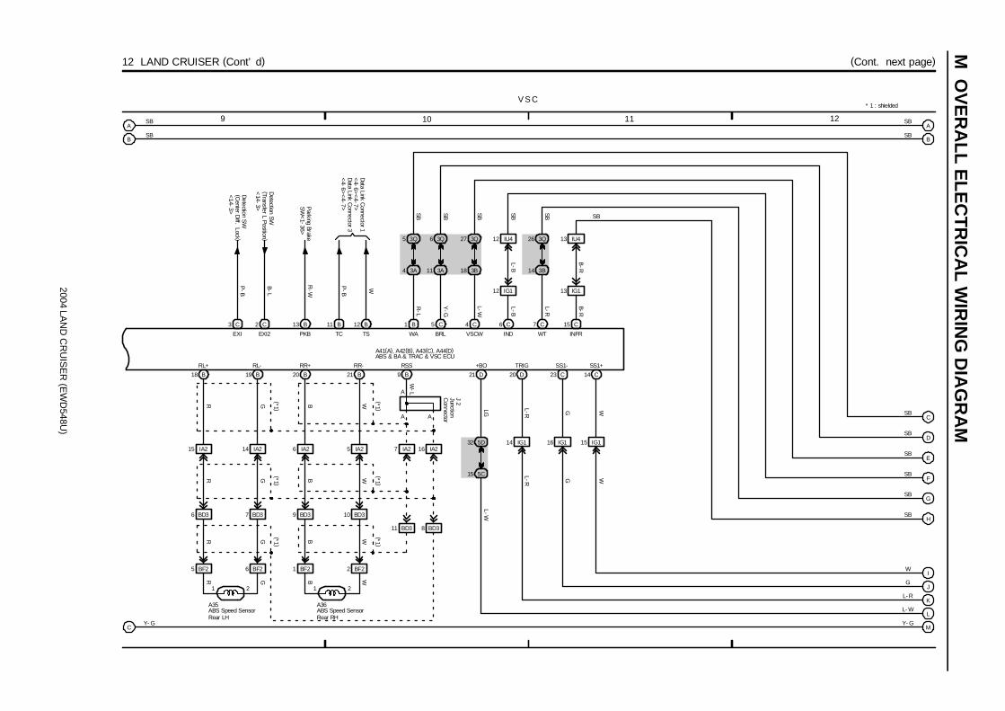
2004 LAN
D C
RU
ISE
R (E
WD
548U)
M O
VE
RA
LL ELE
CT
RIC
AL W
IRIN
G D
IAG
RA
M
9 10 11 12
12 LAND CRUISER (Cont’ d) (Cont. next page)
L
D21
15 5C
SB
3 C 2 C
P-B
B-L
Detection S
W(C
enter Diff. Lock )
<14-3>
Detection SW
(Transfer L Position )<
14-3>
13 IG1
13 B 11 B 5 C 4 C 6 C 7 C 15 C1 B12 B
Parking Brake
SW
<1-36>
13 IU4
SBSBSBSB
W
B-R
B-R
L-R
L-B
L-W
Y-G
R-W
P-B
6 BD3 7 BD3
5 BF2 6 BF2
21
18 B 19 B
9 BD3 10 BD3
1 BF2 2 BF2
21
20 B 21 B
A
A
9 B
A
32 5D
K
D20
R G (*1 )
B W (*1 )
R G (*1 )
B W (*1 )
R G (*1 )
B W (*1 )
WBGR
EXI EXI2 PKB TC TS WA BRL VSCW IND WT INFR
IG1
RL+ RL- RR+ RR- RSS
14
A
B
SB
SB
A41(A), A42(B), A43(C), A44(D)
W-L
Data Link C
onnector 1<
4-6><
4-7>
23 C
G
W
14 C
SS1+
16 IG1
SS1-
15 IG1G
J
WWG
I
3Q5 3Q6 3Q27
3A4 3A11 3B18
12 IG1
12 IU4 3Q26
3B14
A
B
C
E
F
G
H
SB
SB
SB
SB
SB
SB
SB
SB
L- R
L- W
Y- GM
LG
L-R
L-W
L-R
R-L
SB
D
L-B
J 2
15 IA2 14 IA2 6 IA2 5 IA2 7 IA2 16 IA2
CY- G
A36A35
V S C
+BO TRIG
11 BD3 8 BD3
ABS Speed SensorRear LH
ABS Speed SensorRear RH
ABS & BA & TRAC & VSC ECU
JunctionC
onnector
* 1 : shielded
Data Link C
onnector 3<
4-6><
4-7>
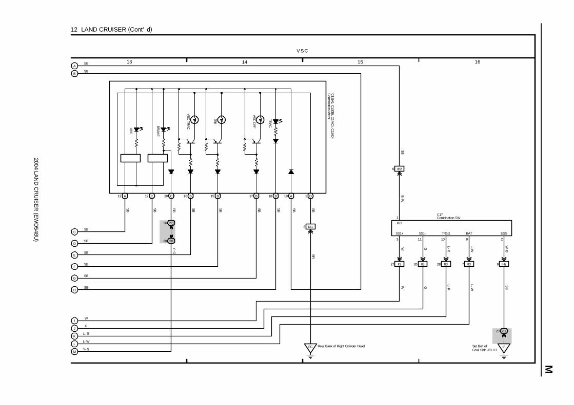
2004 LAN
D C
RU
ISE
R (E
WD
548U)
M
13 14 15 16
12 LAND CRUISER (Cont’ d)
B
C
D
E
SB
F
12 A 19 C 16 B 15 B 17 B 18 B 10 A20 C D
A
G
H
SB SB SB SB SB SB SBSB
1
SS1+
IH29
IFSet Bolt ofCowl Side J/B LH
211
2Q23
3
J
I
SS1- ESS
W G
W-B
G
GW
W
K
L
10 9
L- R
L- W
Y- GM
BRSB
TRA
C
VS
C O
FF
Slip
VS
C TR
ACBR
AK
E
ABS
C12 (A
), C13 (B ), C
14 (C), C
15 (D)
C17
8 IX1
L-W
EC Rear Bank of Right Cylinder Head
L-RSB
SB
SB
SB
SB
SB
L-W
SB
SB
L-R
V S C
6 IH2
2Q36
2B20
Y-G
1
B-W
SB
IG1
TR1G BAT
Com
bination Meter
Combination SW
II37II328II32627 II3

2004 LAND CRUISER (EWD548U)
M OVERALL ELECTRICAL WIRING DIAGRAM
12
34
13
LAN
D C
RU
ISE
R( C
ont.
nex
t pa
ge)
1C1
15A
AM2
1B9
2A10
2E41
7IG
2
ST2
AM
26
10A
RSCA OFF
SRS
4C
19B
A 3E4
7. 5
AM
ET7.
5A
IGN
3Q7
3F3
A
5B
25B
3B
12B
19B
3F2
3Q69
3F8
3Q11
3E11
CC
27B
28B IH
Set
Bol
t of C
owl S
ide
J/B
RH
3F9
3F6
15B
2IB
11
IB1
26B
21
9B
2IT
11
IT1
20B
21
14B
13B
16B
17B
10B
11B
8B
7B
1II4
2II4
4II4
3II4
1BM
22
BM
2
B- GW- RW- R
B- R
W-R
B-R
SB
B- R
W- R
BR
B- W
BR- W
Y- B
Y
Y- V
Y- O
W- R
BR
B- W
BR- W
Y- B
Y
Y- V
Y- O
Y- R
Y- G
Y- GR
Y- P
W- R
BR
B- W
BR- W
B- W
B- Y
SB
SB
SB
SB
B- Y
V- W
P- B
W- B
W- B
Y
Y- B
Y
Y- B
L- R
R
L- R
R
12
43
12
34
21
21
21
IG2
+SL
-SL
+SR
-SR
D+
D-
D2+
D2-
P+
P-P
2+P2
-
RM
ILLA
SIL
TCE1
E2
PL-
PL+
PR
-P
R+
LSP
+LS
P-
Batte
ry
120A
MA
INF1
5
2
I18
J 4
C12(A), C13(B), C14(C)
J15
C25
( A) ,
C26
( B) ,
C27
( C)
1EF
12
EF1
2EA
11
EA1
A15
A16
A28
A27
P21
P22
S17
Po
we
r S
ou
rce
SR
S
+SL
-SL
+SR
-SR
Airb
ag S
enso
rFr
ont L
HAi
rbag
Sen
sor
Fron
t RH
Airb
ag S
quib
( Fro
nt P
asse
nger
Airb
ag A
ssem
bly)
Airb
ag S
quib
( Ste
erin
g W
heel
Pad
)
Combination Meter
Igni
tion
SW
Pre
tens
ione
r LH
Pret
ensi
oner
RH
Junc
tion
Con
nect
or
Cen
ter
Airb
ag S
enso
r A
ssem
bly
Seat
Pos
ition
Sen
sor
Fusi
ble
Link
Blo
ck
Junc
tion
Con
nect
or
(*1)
(*1)(*1)
* 1
: w/ S
ide
Airb
ag*
2 : w
/o S
ide
Airb
ag
3A
( *1)
8A
( *2)
4A
3A
9C
5C
10C
6C
8A
2A
7A
1A
Data LinkConnector 3<4- 7><4- 8>
Data LinkConnector 1<4- 8>Data LinkConnector 3<4- 8>

2004 LAN
D C
RU
ISE
R (E
WD
548U)
M
7 865
13 LAND CRUISER (Cont’ d)
9 A 10 A
A17
8 C 7 C
A20 18 A 16 A A15 A1 13 A 14 A
16 C 13 C 15 C 17 C
A12 A11 5 C 6 C 23 B
3F5
3D30 4C4
4E19
11 A
19 A
3 BM2
18 C 4 C 20 C 19 C
21 B
1 Ia1 8 IU1
C
C
3 IF1
IFSet Bolt ofCowl SideJ/B LH
2Q43
SSL+ SSL- ESL VUPL CSL+ CSL- ESCL VUCL SFL+ SFL- SFR+ SFR- RMSW LBE+ GSW2
ICL+ ICL- ICR+ ICR-SSR+ SSR- ESR VUPR CSR+ CSR- ESCR VUCR
L-W
LG-B
GR
-L
P-L
Y-V
Y-O
L-Y
LG-B
G R Y-R
Y-G
Y-R
Y-G
G-W G
B B
SBSB
G-W
W-B
L-B
GR
-R
LG-B
L-WPGR
LG
L-Y
Y-O
Y-V
3 2 1 4 3 2 1 4 1 2 1 2
4
3
1 2 1 23 2 1 4 3 2 1 4
B
C25(A), C26(B), C27(C)
* 1 : w/ Side Airbag* 2 : w/o Side Airbag
S11 S13S18 S19
(*1 )
C29
(*1 )
C30
(*1 )
S12
(*1 )
S14
(*1 )
(*1 )
(*1 )
(*1 )
(*1 )
(*1 )
(*1 )
(*1 )(*1 )
(*1 )
(*1 )
(*1 )
(*1 )
(*1 )
(*1 )
(*1 )
(*1 )
(*1 )
(*1 )
(*1 )
J 7
(*1)
(*2)
R40
Engine C
ontrolM
odule<4-16>
S R S
22 B
MPX2
Multiplex C
omm
unicationS
ystem<
1-39>(*1 )
(*1 )(*1 )
(*1 )(*1 )
(*1 )
SSL+ SSL- ESL VUPL CSL+ CSL- ESCL VUCL
SSR+ SSR- ESR VUPR CSR+ CSR- ESCR VUCR
1 2 1 2Y Y Y Y
Roll S
ensing of Curtain S
hieldA
irbags Cutoff S
W
Side AirbagSquib LHSide Airbag Sensor Front LH Side Airbag Sensor Rear LH
Curtain ShieldAirbag Squib LH
Center Airbag Sensor Assembly
Side AirbagSquib RH
Side Airbag Sensor Front RH Side Airbag Sensor Rear RHCurtain ShieldAirbag Squib RH
JunctionConnector
G-W
(*1 )
G-W
(*1 )
G
Buckle SW LH<25- 3>
11 IF2
SB
(*1 )
A
A
SB
(*1 )
JunctionC
onnector
J12

2004 LAND CRUISER (EWD548U)
M OVERALL ELECTRICAL WIRING DIAGRAM
12
34
14
LAN
D C
RU
ISE
R
2C1
2A
1B
120AJ/B NO. 2
120A MAIN
140A ALT
II
F15(
A), F
16( B
) , F1
7(C
)
B- G
I18
Bat
tery
IG1 NO. 3 Relay
12
35
3Q39
3C1
SB
7. 5A AM1
2E39
B- G
1C
B- G
120AJ/B NO. 3
W- R
L- B
7. 5A MET
3Q7
3E4
B- G
2 7
AC
C
IG1
IG2
ST2
AM
14 6
AM
2
91B
11C
15A AM2102A
412E
W- R
B- R
B- R
ABS & BA &TRAC & VSCECU<12- 9>
EB
15
EC
IIS
et B
olt o
fC
owl S
ide
J/B
RH
13IN
25
IN2
1EB
16
EB
12
EB
112
EB1
M
EB1
118
EB1
12
12
12
2IX
1
14IN
2
36
9
104
15
2
4
10A
14B
21
53
3E6
W-B
L- B W- B W- B
G- Y
G
G- R
G- B
G- Y
G
G- R
G- B
G
G- R
W- B
W- B
Y- GY- G
P- B
Y- G
SBSBSB
W- B
Engine Control Module<5- 12>
R- LR- LR- L
ABS & BA & TRAC & VSCECU<12- 9>
P- B
3EB
1B- LB- L
W-B
B-L
W- B
3Q56
3Q28
3B3
6D38
6D39
D 4
D 6
D 5
CenterDiff. Lock
AA
C12(A), C13(B)
J 4
B- R
6Ib
2R- L
6D32
6D31
3Q
20 54
3B
5IX
1SB B- L
C 5
C 2
3Ib
22
Ib2
3Ib
12
Ib1
B
B- R B- R
BB
B-R
Ib2
10Ib
21
6D5
6D4
6B2
6B3
G- Y
G
G- R
G- B
2526
272
113
B
B- R(*1)
(*2)
( *1)
( *2)
C28
A45
DEF
C
2WD
4WD
B- R
B-R
12
53
192D
10A GAUGE1
R- L
IG1 NO. 2 Relay
Set B
olt o
fC
owl S
ide
J/B
RH
IFSe
t Bol
t of
Cow
l Sid
e J/
B L
H
17 4D5 4C
R- L(*1)
R-L
( *1)
R-L
( *2)
R-L
*1 :
w/ N
avig
atio
n Sy
stem
*2 :
w/o
Nav
igat
ion
Sys
tem
2E37
2Q77
10A GAUGE2
3E3
53E
20A DIFF
L- B
R- L
Rea
r B
ank
of R
ight
Cyl
inde
r H
ead
SB
Po
we
r S
ou
rce
Ce
nte
r D
iffe
ren
tia
l L
oc
k
DE
FC
2WD
4WD
RE
L2M
2M
1R
EL1
GN
D
2WD
4WD
IG
B- LEngine Control Module<5- 12>
156C
Center Diff. Lock ControlMotor
Center Diff. Lock Control Relay
Combination MeterDetection SW(Center Diff. Lock)
Detection SW(Transfer L Position)
Detection SW(Transfer Neutral Position)
Igni
tion
SW
A/C Control Assembly
Junc
tion
Con
nect
or
Center ClusterIntegration Panel
Fusi
ble
Link
Blo
ck
W- B

2004 LAN
D C
RU
ISE
R (E
WD
548U)
M
1 2 3 4
15 LAND CRUISER
P ower S ource Au tomatic G la re- Res is tan tEC M irror w ith C ompass
10ADOME
2C1
2E39 2E37
IF Set Bolt Cowl SideJ/B LH
1
2
5
3
140AALT
120AJ/B NO. 2
112L
1
4
B- R L- B
B-W
W-B
B-R
B-G
W- BBattery
F15(A), F16(B)
I22
IG1NO. 2Relay
10AECU- IG1
2L19
B- W
IG
4AM1 IG1
ACC
2
I18
E
Ignition SW
Inner Mirror
Fusible LinkBlock
120AMAIN
2 A 1 B
1C1
30ABAT
1B24
W-B
L-Y
8
1
+B2
O 5
GND
OverheadJ/B
2L14
3B25
7. 5AAM1
3Q17
2Q79
2L2
B-G
2
1
ShortPin(A)
L-O
L-OSB
W- B
G arage D oor O pener

2004 LAND CRUISER (EWD548U)
M OVERALL ELECTRICAL WIRING DIAGRAM
12
34
16
LAN
D C
RU
ISE
R
2
ACC
IG1
AM
1
3
12
53
2C1
7. 5A ACC
2E39 7. 5A AM1
120A J/B NO. 3
140A ALT
IFS
et B
olt o
fC
owl S
ide
J/B
LH
B- GB- R
I18
ACC Relay
Bat
tery
2E40
6B5
6D2
34
21
3Q52
IX13
4IX
1
3Q51
3Q50
7A6
SB
7A5
B
B
ACC CUT Relay
B- R
SB
B- R
Engine ControlSystem<4- 2>
2Q44
SB
16
SB
SB
G- R
Y- R
W
G
Y
W
SB
SB
SB
SB
SB
SB
SB
G- R
G
Y- R
Y
W
W- B
GR
SB
MM
86
7
MH
MV
M+
M+
MV
MH
76
8
MM
AA
42Q
142J
2J4
2Q48
472Q
112J
113J
663Q
3Q57
3J10
33J
613Q
D D
2Q43
EE
IF2
4
13 IF2
IF2
15IF
2IF
25
IF2
19IF
211
Select SWOperation SW
Right/Down
Left/Up
Down
Up
Right
Left
87
23
109
4
B
MR
VM
RH
EM
+M
LVM
LH
SB
LHLH
RH
RH
Re
mo
te C
on
tro
l M
irro
rP
ow
er
So
urc
e
Set B
olt o
fC
owl S
ide
J/B
LH
IF
R 5
J 6
J12
33 3QS
B
R32
R33
3C1
1B
1C
B- G
B- G
F16(B), F17(C)
120A J/B NO. 2
Igni
tion
SW
Rem
ote
Con
trol M
irror
SW
Rem
ote
Con
trol M
irror
LH
Rem
ote
Con
trol M
irror
RH
Fusible Link Block
Junc
tion
Con
nect
or
Junc
tion
Con
nect
or
B
6B4
6D3

2004 LAN
D C
RU
ISE
R (E
WD
548U)
M
1 2 3 4
17 LAND CRUISER
2
ACC
IG1AM1 4
1
2
5
3
2E37
2C1
10A E
CU
-IG1
2L192E39
7. 5A AM
1120A J/B
NO
. 2140A ALT
IF Set Bolt ofCowl Side J/B LH
F16
B-G
L-B
L-B
B-R
I18
IG1 NO. 2Relay
Battery
25A S
UN
RO
OF
10 2L
1
Dow
n
Up
1 2
Close
Open
5 4
3
M 3
IF Set Bolt ofCowl Side J/B LH
8 5 2
4 3 9 10 7
2L11
W- B
B-WB
LB
B-W
W-B
G-Y
R
R-W
R-Y
W-B
M 2
M oon R oo fP ow er S ource
Body E
CU
<1-40>
IG +B PWS
UP DOWN OPEN CLOSE E
M
P2
P1
SGND
PSW2
PSW1
MTR+
MTR-
Ignition SW
Moon Roof Control ECU
Moon Roof Control SW
Fusible Link Block
9 2D
1 IE2
W-B
W-B
1
GND
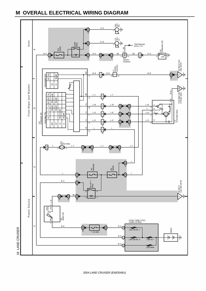
2004 LAND CRUISER (EWD548U)
M OVERALL ELECTRICAL WIRING DIAGRAM
12
34
18
LAN
D C
RU
ISE
R
2
AC
C
IG1
AM1
4
12
35
15A
WAS
HER
3A9
3C1
3Q39
2C1
2E39
1B
1C
7. 5A AM1
120A J/B NO. 3
120A J/B NO. 2
140A ALT
IISe
t Bol
t of
Cow
l Sid
e J/
B R
H
F15(A), F16(B), F17(C)
B- G
B- G
B- R
B- G
I18
IG1
NO
. 3R
elay
Batte
ry
120A MAIN2A
M2 3 1A56
1B68
OFF INT
LO
+B+2
+1
HI
INT1
INT2
+SB1
Off
On
WF
EW
Fron
t Was
her S
WFr
ont W
iper
SW
32II3
M
AA
IIS
et B
olt o
f Cow
lS
ide
J/B
RH
EBFr
ont R
ight
Sid
eof
Fen
der
Apr
on
3E35
1C
10A
HO
RN
211B
1A4
1A15
2B9
2Q24
CC
8IH
2
11
41
23
E
178
716
112
+B+2
+1+S
WF
EW
5W
-B
L
L- R
L- B
L- W
L- Y
W- B
L
L- R
L- B
L- W
W- B
G- O
G- W
G- R
SB SB G- O
W- B
L- Y L- Y
L- R
L- W
L- B
L
+2+1
BS
HO
RN
Rel
ay
1
SB
C
Theft DeterrentECU<1- 17>
6
33II3
34II3
35II3
2E37
2Q77
L-B
SB
25A
WIP
ER
3A7
3G11
2A1
2D38
3A13
3A10
3A15
3G12
3G4
3G8
J 3
J14
L
L
C19
H10
H 9
C18
Horn
F 5
2EA
2 L
L
W 1
L- Y
Fro
nt
Wip
er
an
d W
as
he
rP
ow
er
So
urc
e
B- G
B- G
Ho
rn
Com
bina
tion
SW
Com
bina
tion
SW
Fron
t Wip
er M
otor
Hor
nLH
Hor
nR
H
Igni
tion
SW
Washer Motor
Junc
tion
Con
nect
or
Fusible Link Block
JunctionConnector
II331
L- Y
3II3

2004 LAN
D C
RU
ISE
R (E
WD
548U)
M
1 2 3 4
19 LAND CRUISER
2
ACC
IG1AM1 4
1
2
3
5
15AWASHER
3A93C13Q39
1
2
5
3
2Q77 2E37
2C1
15A R
R W
IPER
2K22E39
1 B1 C
7. 5A AM
1
120A J/B N
O. 3
120A J/B N
O. 2
140A ALT
IF Set Bolt ofCowl Side J/B LH
II Set Bolt ofCowl Side J/B RH
F16 (B ), F17 (C)
B-G
B-G
L-B
L-B
SB
B-R
SB
B-G
I18
IG1 NO. 2Relay
IG1 NO. 3Relay
Battery
P ow er S ource R ear W ipe r and W asher
5 BP3 2 EA2
M
1
2
M
BJ Under the Driver’ s Seat
Wash
OFF
INT
WR +1R C1R
131012
EW
ON
Wash
36 II3 4 II3 5 II3
2D39
2A14
1A48
1B54
3 ID4
2 ID4
4 BP3 3 BP3
L
L L
L
1 4
3
2
W-B
L-O
W-B
W-B
P
P
P L-B
L-Y
L-B
L-Y
B A
B A
C19
R30
L-B
L-Y
L-O
L-YL-Y
L-O
IISet Bolt of CowlSide J/B RH
3E35
2
A
A
P L-B
L- Y
W- B
3 II3
W-B
+1 -
+ S
W-B
W-B
L
L L
Combination SW
Ignition SW
Rear Wiper Motor
Fusible Link Block
JunctionC
onnector
J 3
JunctionC
onnector
J22
Washer M
otorW
1
Rear W
asher SW
Rear W
iper SW
3 4 5 6 2
L-O
L-Y
L-OL
Rear Wiper RelayR31
L
L-Y
1 BH1
BH21 (*1)
(*2)
2 ID4
5 BH2
BH23 (*1)
(*2)
4 BH1
BH27
3 BH1
BH28 (*1)
(*2)
* 1 : w/ Navigation System* 2 : w/o Navigation System
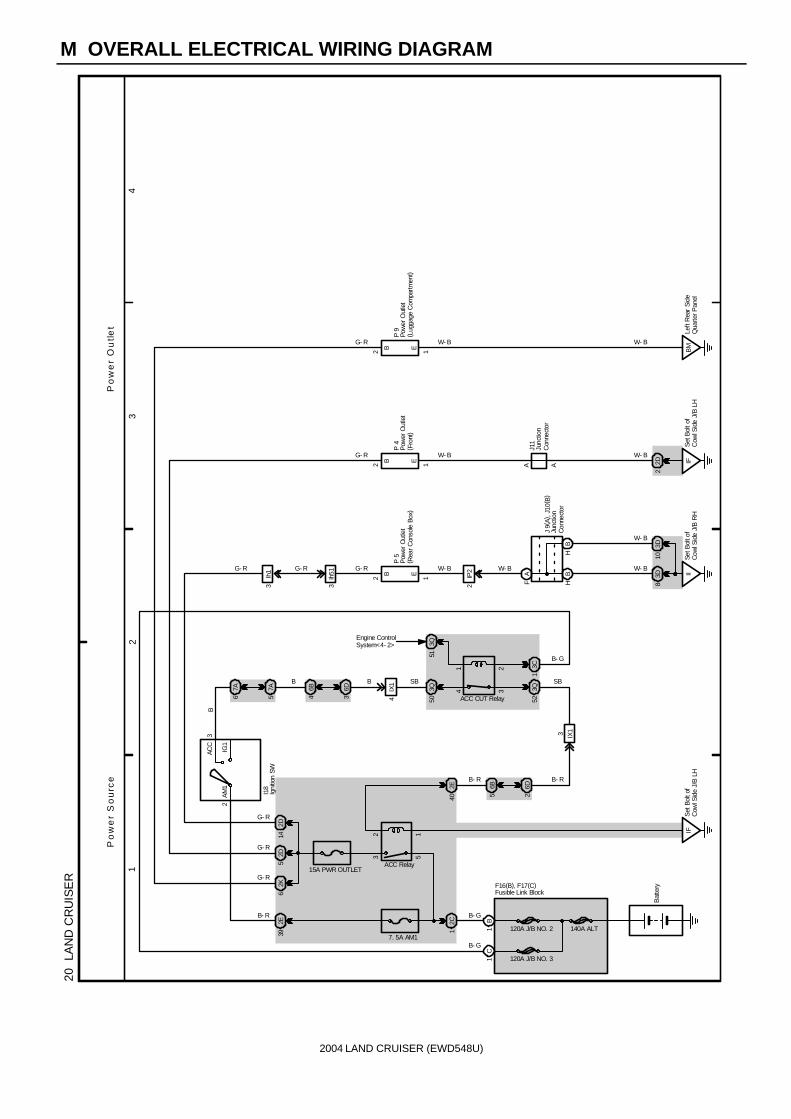
2004 LAND CRUISER (EWD548U)
M OVERALL ELECTRICAL WIRING DIAGRAM
12
34
20
LAN
D C
RU
ISE
R
2
ACC
IG1
AM
1
3
12
53
2C1
15A PWR OUTLET
2E39 7. 5A AM1
120A J/B NO. 2 140A ALT
IFS
et B
olt o
fC
owl S
ide
J/B
LH
B- GB- R
I18
ACC Relay
Bat
tery
2E40
6B5
6D2
34
21
3Q52
IX13
4IX
1
3Q51
3Q50
6B4
SB
6D3
B
B
ACC CUT Relay
B- R
SB
B- R
Engine ControlSystem<4- 2>
2D5
2K6
2D14
G- R
G- R
G- R
P 5
EB
2 1
G- R W- B
EB2 1
G- R W- B
IFS
et B
olt o
fC
owl S
ide
J/B
LH
P 9
EB2 1
G- R W- B
BM
Left
Rea
r S
ide
Qua
rter P
anel
3Ih
51
2IP
2
FA
HB
HB
AA
3D8
3D10
2D2
W- B
W- B
W- B
W- B
J11
J 9(
A), J
10( B
)
W- BG- RG- R
Po
we
r O
utl
et
Po
we
r S
ou
rce
IISe
t Bol
t of
Cow
l Sid
e J/
B R
H
3C1
1B
1C
B- G
B- G
120A J/B NO. 3
F16(B), F17(C)
Igni
tion
SW
Pow
er O
utle
t( R
ear C
onso
le B
ox)
Pow
er O
utle
t( L
ugga
ge C
ompa
rtmen
t)
Junc
tion
Con
nect
or
Junc
tion
Con
nect
or
Fusible Link Block
P 4
Pow
er O
utle
t( F
ront
)
B
7A6
7A5
3Ih
1
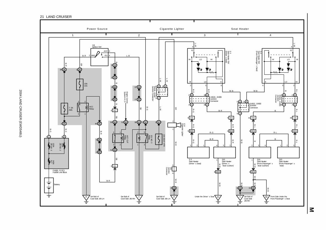
2004 LAN
D C
RU
ISE
R (E
WD
548U)
M
1 2 3 4
21 LAND CRUISER
2
ACC
IG1AM1
3
B- R
1
2
5
3
15ACIG
2D12E39
7. 5AAM1
2C1
IF Set Bolt ofCowl Side J/B LH
1 C 1 B
6B4
6D3
3Q50 3Q51
3
4
2
1
2E40
6B5
6D2
3 IX1
3Q52
II
B-G B-R
SB
B-R
GR
BB
B- R
I18
F16(B), F17(C)
120AJ/B
NO
. 3140AA
LT
120AJ/B
NO
. 2
Battery
4 IX1
SB
ACCRelay
Engine Control
System<
4-2>A
CC
CU
TR
elay
1
2
3
5
3Q39 3C1
15A SE
AT HTR
3D2
2E37
2Q77
IG1 N
O. 3
Relay
IFSet Bolt ofCowl Side J/B LH
2D2
2
1
LO HIHI
HI LO E
3 5 6
4
HI LO HI
4
IG IG
HIE LO
6
BK Front Side Under theFront Passenger’ s Seat
5
BJ
3
8 ID3 9 ID3 41 IV4 40 IV4
5 BM3 6 BM3 6 BO3 5 BO3
8 BM3
1
3 2 2 3
8 BO3
GR
W-B
W-B
L-W
R-G
B-R B R-L
R-G
W-B
R-G
R-G
B- R
B-RB
-R
B
R-L
B-L
R-L
B R-L
W-B
W-B
W-B
A
A
J11
B B
B A
C B
A A
J20 (A), J21 (B
)
D B D B
E A
II Set Bolt ofCowl SideJ/B RH
Under the Driver’ s Seat
1
J18(A), J19(B)
C B
A A
B B
B A
2 1 4 3 3 4 1 2
D B D B
E AS 3
S 4
L- B
L-W
L-W
SB
B-G
L-W
C10
B-G
B- R
R- G
B
R- L
S 9 S15
J18(A), J19(B)
W- B W- B
S16 S10
P ow er S ource C igare tte L ighte r S eat Heate r
4
J20 (A ), J21 (B )
L-W
3D1
W-B
Set Bolt ofCowl Side J/B RH
Cigarette Lighter
Ignition SW
Seat Heater S
W(D
river’s S
eat )
Seat Heater S
W(Front P
assenger’s Seat )
Seat Heater(Driver’ s Seat)
Seat Heater(Front Passenger’ s Seat)
JunctionConnector
JunctionConnector
Junction Connector
JunctionC
onnector
JunctionC
onnectorSeat Heater(Front Passenger’ s Seat Cushion)
Seat Heater(Driver’ s Seat Cushion)
Fusible Link Block
3K31 W-B
W-B
W-B
B
7A6
7A5
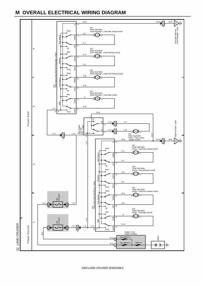
2004 LAND CRUISER (EWD548U)
M OVERALL ELECTRICAL WIRING DIAGRAM
12
34
22
LAN
D C
RU
ISE
R
120A J/B NO. 2
140A ALT
Batte
ry
B- G
SLD
RS
LDF 8
4
FDW
NFU
P 109
RC
LRR
CLF 1
5
LDW
NLU
P 23
Slid
eFr
ont V
ertic
alR
eclin
ing
Rea
r Ve
rtica
l
12 B Front
Up
Front
Up
Rear
Down
Rear
Down
21 M
G
R- WY- R
12 M
G- B
R- B
21 M
G- R
R- L
12 M
G- Y
R- Y
BJU
nder
the
Driv
er’
s S
eat
8B
M3
6E
W- B W- B
2C1
30A
LH S
EA
T
12K
10B
M3
E2
12
4B
2
3
1BN
12
BN
1
LFLR L- W
L- R
L- R
L- W
Y-R
Y- R Y- R
W- B
W- B
W-B
Y-R
Po
we
r S
ou
rce
Po
we
r S
ea
t
W- BW- B
E 6 BO
38
Fron
t Sid
e U
nder
the
Fron
t Pas
seng
er’
s Se
atB
K
R- Y
G- Y
M1 2
R- L
G- R
M1 2
R- B
G- B
M1 2
Y- RR- W
GM2 1
Down
Rear
Down
Rear
Up
Front
Up
FrontB12
Rea
r Ve
rtica
lR
eclin
ing
Fron
t Ver
tical
Slid
e
23
LUP
LDW
N
51
RC
LFR
CLR
109
FUP
FDW
N
48
SLD
FS
LDR
W- B
10B
O3
21 M
B-G
30A
RH
SE
AT
3C1
3K1
P24
L 3
P23
P31
P32
P30
P33
P29
P25
P28
P27
P26
Y- R
Y- RY- R
1B
1C
120A J/B NO. 3
F16(B), F17(C)
B- G
B- G
Lum
bar S
uppo
rtC
ontro
l SW
( Driv
er’
s Se
at)
Pow
er S
eat C
ontro
l SW
( Driv
er’
s S
eat)
Pow
er S
eat C
ontro
l SW
( Fro
nt P
asse
nger
’s
Sea
t)
Power Seat Motor(Driver’ s Seat Front Vertical Control)
Power Seat Motor(Driver’ s Seat Lumbar Support Control)
Power Seat Motor(Driver’ s Seat Rear Vertical Control)
Power Seat Motor(Driver’ s Seat Reclining Control)
Power Seat Motor(Driver’ s Seat Slide Control)
Power Seat Motor(Front Passenger’ s Seat Front Vertical Control)
Power Seat Motor(Front Passenger’ s Seat Rear Vertical Control)
Power Seat Motor(Front Passenger’ s Seat Reclining Control)
Power Seat Motor(Front Passenger’ s Seat Slide Control)
Fusible Link Block

2004 LAN
D C
RU
ISE
R (E
WD
548U)
M
1 2 3 4
23 LAND CRUISER
2C1
1 B1 C
120A J/B N
O. 3
120A J/B N
O. 2
140A ALT
F15(A), F16(B), F17(C)
B-G
I18
Battery
IG1 N
O. 3 R
elay 1
2
3
5
3Q39 3C1
2E37
2Q77
SB
7. 5A A
M1
2E39
B-G
2
ACC
IG1AM1 4
1B24
30A B
AT
1C1
2 A
B-G
120A M
AIN
Short Pin (A)
L-O
B-R
L-B
20A TIL &
TEL
10A EC
U-IG
2
10A EC
U-B
2
3D383D37 3D39
3B25
L-O
(Shielded )4 B
+B
4 A
IG
1 A
ECUB
2 A
VC
5 A
MSW
14 B
SG1
5 B
SIN1
13 B
S5V1
15 B
COM1
6 B
F/B1
16 B
B1
7 B
A1
1 B
A2
8 B
B2
2 B
F/B2
9 B
COM2
12 B
S5V2
11 B
SIN2
10 B
SG2
AA
PLBY
G-W
G-R
G-Y
V-YV
PVBG
G-W
G-R
G-Y
V-YV
(Shielded )
B-Y
B-R
B-WBRGW
8 7356411465387
816
L-W
B-W
G-B
W-B
(Shielded )
SG1 SIN1 S5V1 COM1 F/B1 B1 A1 A2 B2 F/B2 COM2 S5V2 SIN2 SG2
A
TelescopicLong
Tilt Up
TelescopicShort
TiltDown
VC MSW
(Shielded )
(Shielded )
3 A
MPX1
Multiplex
Com
munication
System
<1-38>
B-G
A
6 A
GND
3D42
8 II5 9 II5 12 II5 11 II5 10 II5 18 II3 15 II3 17 II3 16 II3
T 9 T 4
T 7(A), T 8(B)
C17
J 1
W-B
Pow er T ilt and P ow er Te lescopicP ow er S ource
Set Bolt ofCowl Side J/B RH
IISet Bolt ofCowl Side J/B RH
II
2
1
Com
bination SW
Ignition SW
Telescopic Motor
Tilt and Telescopic ECU
Tilt Motor
JunctionConnector
Fusible Link Block
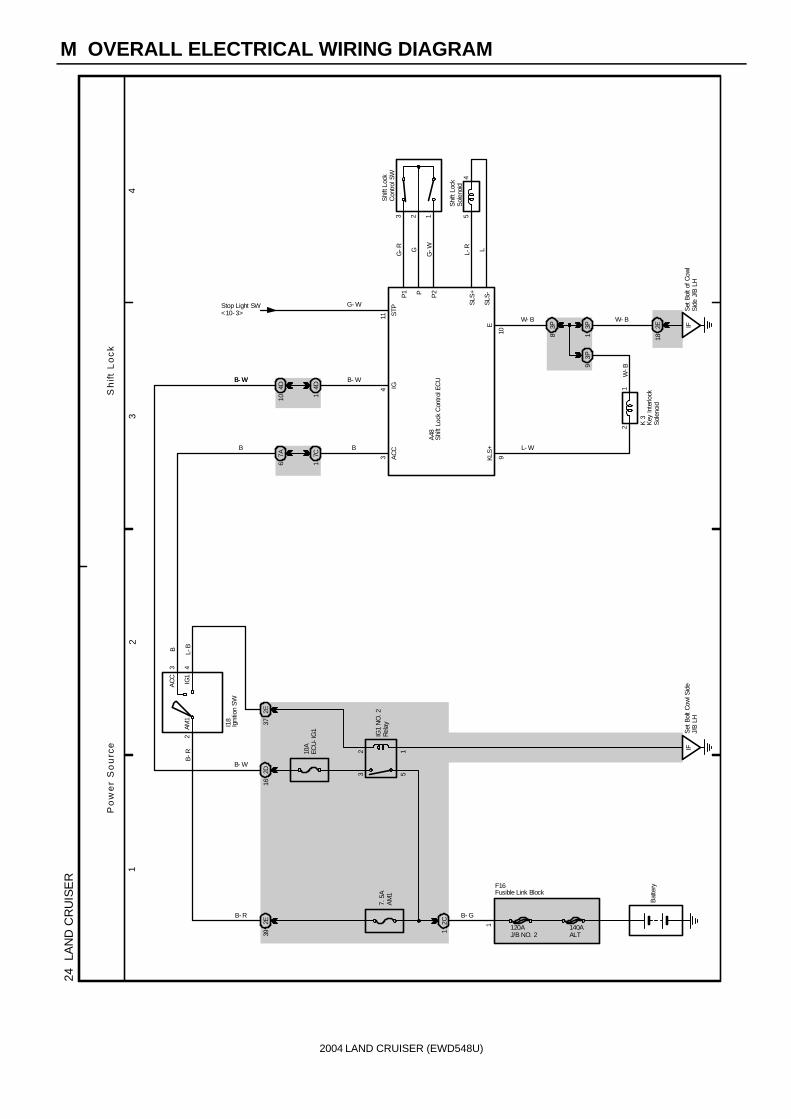
2004 LAND CRUISER (EWD548U)
M OVERALL ELECTRICAL WIRING DIAGRAM
12
34
24
LAN
D C
RU
ISE
R
2
AC
C
IG1
AM1
3
B-R
2E39
7. 5
AA
M1
2C1
IFS
et B
olt C
owl S
ide
J/B
LH
B- GB- R
I18
Bat
tery
Po
we
r S
ou
rce
Sh
ift
Lo
ck
12
53
10A
ECU
-IG
1
2D16
2E37
4
54
3 2 1
G-R G
G-W
Shi
ft Lo
ckS
olen
oid
Shi
ft Lo
ckC
ontro
l SW
L-R L
114
3
Set
Bol
t of C
owl
Sid
e J/
B L
HIF2E
18
21
109
W-B
G- W
B- W
L- W
W- B W- B
AC
CIG
STP
Stop Light SW<10- 3>
KLS
+E
P1 P P2
SLS
+
SLS
-
7C1
7A6
3P8
3P1
3P9
K 3
A48
IG1
NO
. 2R
elay
L-BB
B- W
B- W
120AJ/B NO. 2
140AALT
F16
Igni
tion
SW
Key
Inte
rlock
Sol
enoi
d
Shi
ft Lo
ck C
ontro
l EC
U
Fusible Link Block
1
4D1
4D10
B
B- W
B

2004 LAN
D C
RU
ISE
R (E
WD
548U)
M
1 2 3 4
25 LAND CRUISER
Battery
120AMAIN
120AJ/B NO. 2
15A AM
2
1C1
1B9 2E39
1
2
5
3
2Q65 2E37
IG1NO. 2Relay
B-G
B-R
IF Set Bolt ofCowl Side J/B LH
L-B
B- R 2
7
ACC
IG1
IG2
ST2
AM1 4
6AM2
7. 5AAM1
2 A 1 B
2C1
B-G
1B24
30ABAT
15AA/C
2D6
L-O
W-R
R-L
SB
10AGAUGE1
I18
F15(A), F16(B)
W- R B- R2A10
2E41
W-R
Seat Belt
12 D11 D10 A
1 D 11 C
3Q7 3Q44
3E4 3B25
30 A
22 C
I- SBW
3D26
3K21
2Q41
2K182G103 BV1
5 BO23 BU12
1
3
2
GG
G
GG
-W
GSB
4 BO2
1 BV1
BKFront SideUnder the FrontPassenger’ s Seat
SB SBSB
BJUnder theDriver’ s Seat
A
A
E
E
1 BU1
ECRear Bank of RightCylinder Head
8 IX1
A
AJ 4
J14
7. 5A M
ET
10A EC
U-B2
B- R
L-O
C12 (A
), C14 (C
), C15 (D
)
W-B
W-B
W-BB
R
W-B
G
BR
W-B
P ower S ource S eat Be lt W arning
J22
S 8
B 6
R-L
L-B
SB
Body E
CU
<1-38>
SB
140AALT
3N21
3N11
2D25
R-L
5 BM2
3
2
4 BM2
GG
G
B 5
W-B
W-B
G
G (*2 )
(*1 )
20
8
R-L
(*2 )
(*1 )
IGIG
S/BW
R-L
(*1 )
(*2 )
(*1 )
1
2
C28
* 1 : w/ Navigation System* 2 : w/o Navigation System
A45(A), A47(C)
BuckleSW LH
Buckle S
W R
H
Com
bination Meter
Ignition SW
Seat Belt
Warning O
ccupantD
etection Sensor
A/C ControlAssembly
Junction Connector
Center C
lusterIntegration P
anel
JunctionConnector
Fusible Link Block
JunctionC
onnectorB
uzzer
1
Center A
irbag Sensor
Assembly<
13-7>G
BMLeft Rear SideQuarter Panel
W-B
W-B
ShortPin(A)
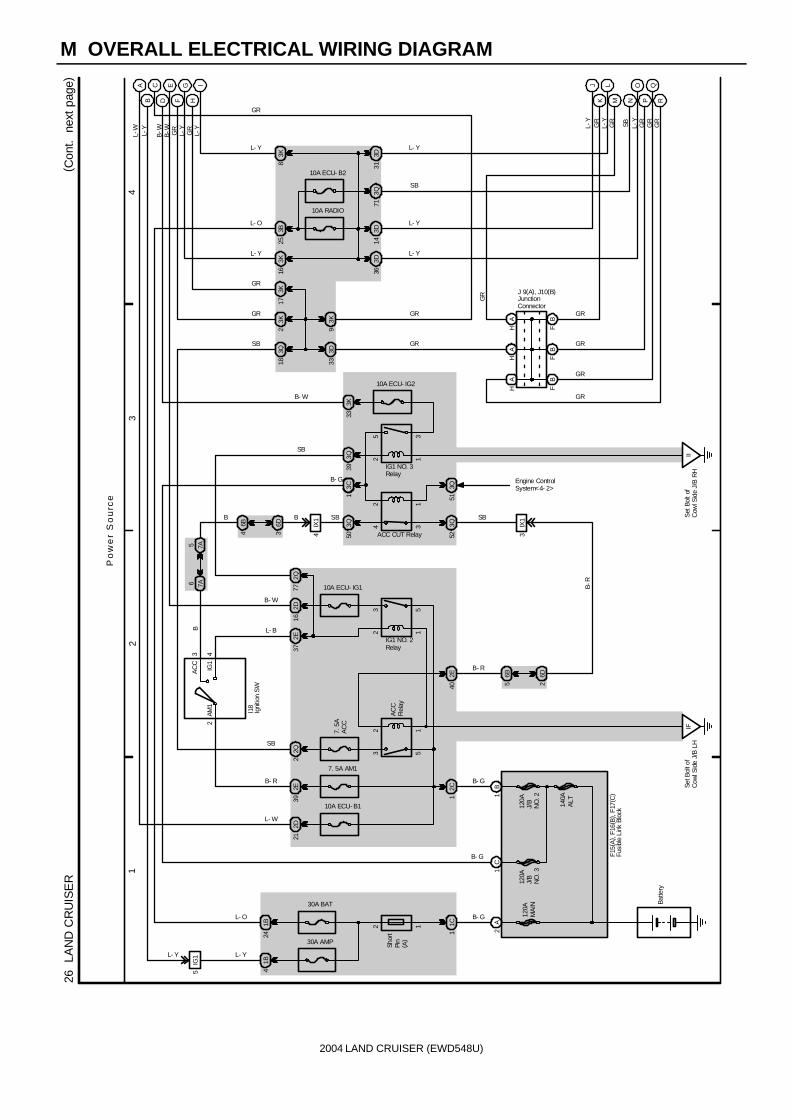
2004 LAND CRUISER (EWD548U)
M OVERALL ELECTRICAL WIRING DIAGRAM
12
34
26
LAN
D C
RU
ISE
R( C
ont.
nex
t pa
ge)
3D33
3Q18
Po
we
r S
ou
rce
3K9
SB
2A
1B
F15(
A) ,
F16(
B) ,
F17(
C)
120A
MA
IN
120A
J/B
NO
. 2
Batte
ry
2
AC
C
IG1
AM1
3
1C1
30A BAT
1B24
30A AMP
1B4
7. 5A AM1
2E39
2C1
12
53
IFSe
t Bol
t of
Cow
l Sid
e J/
B L
H
7. 5
AA
CC
2E40
6B5
6D2
3IX
1
34
12
3Q52
6B4
6D3
3Q504
IX1
3C1
10A RADIO
3B25
3D31
3D14
L- Y
L- Y
HA
HA
FB
Shor
tPi
n( A
)
B- G
B- G
I18
2Q2
B
Engine ControlSystem<4- 2>
B SB
AC
CR
elay
B- R
SB
ACC CUT Relay
GR
L- Y
L- O
B- R
SB
140A
ALT
10A ECU- B1
2D21
L- W
12
53
2E37
2D16
10A ECU- IG1
4
L- B
B- W
IG1 NO. 2Relay
3K2
HA
FB
FB
10A ECU- B2
3Q71
3K16
L- YL- Y
L- O
SB
GR
J 9(A), J10(B)
GR
GR
GR
GR
5IG
1L- Y
3D36
AB
C EF
G JK
LM N
OP
QR
GR
GR
L-Y
L-Y
GR
SB L-Y
GR
GR
GR
L-Y
GR
B-WL-
YL-
W
3Q51
C1
B- G
120A
J/B
NO
. 3
B- G
Igni
tion
SW
JunctionConnector
Fusi
ble
Link
Blo
ck
B-R
12
6 7A5 7A
2Q77
12
35
B
3K17
3K8
10A ECU- IG2
3K33
3Q39
IIS
et B
olt o
fC
owl S
ide
J/B
RH
IG1 NO. 3Relay
DB
-W
HI
L-Y
GR
GR
L- Y
SB
B- W
GR
GR
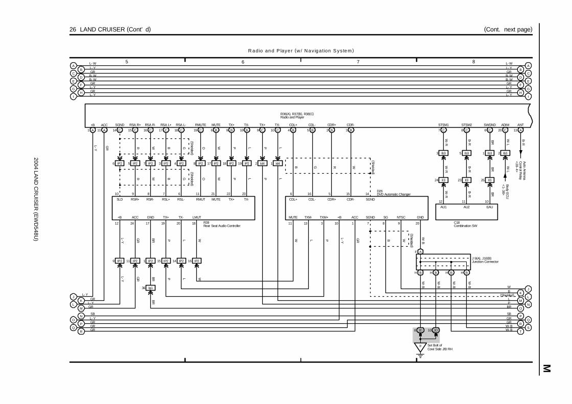
2004 LAN
D C
RU
ISE
R (E
WD
548U)
M
5 6 7 8
26 LAND CRUISER (Cont’ d) (Cont. next page)
C18
101112
SWGNDSTSM2STSM1
C14 15 C 16 C 17 C 18 C 19 C
23
R W B G O
R W B G O
EAUAU2
SGND RSA R+ RSA R- RSA L+ RSA L- RMUTE
SLD RSR+ RSR- RSL+ RSL- RMUT
AU1
BR
B-R
W-R
GR
L-Y
11 IP29 IP2
+B ACC
12 24
L-Y
GR
(Shielded )
(Shielded )
C6C8C7W
-R
L-Y
GR
222111678910
6 B 9 B 10 B
W P L
W P L
MUTE TX+ TX-
MUTE TX+ TX-
ANT
B-R
A13
3 Ib3 5 Ib3 1 Ib3
24 II3 23 II3 25 II3
W-R
B-R
BR
B-R
BR
+B
A1 A
ACC
11
4 IP23 IP27 IP25 IP26 IP2 8 IP2 IP217 18 IP2 19 IP2
R39
GND
17
J 9(A), J10(B)
AF
BHBH
W-B
10 3D
Set Bolt ofCowl Side J/B RH
II
IP216IP214IP215
P
TXM+
313
TXM-MUTE
182019 110
W-B
W-B
8 3D
GND
20
GR
L-Y
ACC
W
+BLMUT
(Shielded )SGND
14
W
CDR-
15
CDR-
B3
R
CDR+
5
CDR+
B2
G
CDL-
16
CDL-
B5
B
CDL+
6
TX+
L
TX-
11
CDL+
B49 C 10 C
P L
P L
TX+ TX-
2 Id4 1 Id4
7
SGND
8
SG
9
NTSC
WB
(Shielded )
A
C
E
G
B
FL- YGR
B- W
L- YL- W
GR
J
L
O
Q
K
M
N
P
R
GRL- Y
L- Y GR
SBL- YGRGRGR
BR P L W
P L W
D26
R adio and P laye r (w / Nav igation S ystem)
AB
C
EF
G
JK
LM
NO
PQ
R
R36(A), R37(B), R38(C)
L- WL- YGR
B- WGRL- Y
WB
(Shielded)LP
BR
SBGRGR
1 IP2
36 Ig1
BRB
R
BH BH
ST
W-B
W-B
W- BW- B
Auto AntennaC
ontrol Relay
<28-4>
Combination SW
DVD Automatic Changer
Junction Connector
Rear Seat Audio Controller
Radio and Player
ADIM
W-L
C20
2 Ib3
W-L
Body EC
U<
1-38>
D B- W DB- W
IH
L- YGR H
I
GRL- Y

2004 LAN
D C
RU
ISE
R (E
WD
548U)
M O
VE
RA
LL ELE
CT
RIC
AL W
IRIN
G D
IAG
RA
M
9 10 11 12
26 LAND CRUISER (Cont’ d) (Cont. next page)
R36(A), R37(B), R38(C)
Ig118Ig117Ig120Ig119Ig115Ig116Ig121Ig122Ig142
A7
MUTE
A
AMP+
3 A
1 B
AMP
B-RB
-R
RR
37
FL
9
RGBBR
YRG
17A
SGND
16
SGND
B11
GND
B10
R. R
B14 5 B
F. L
Ig1
20
GND
A
ID440ID439
T14
12
3 BC3 BC32B Y3 BA3 BA32
B Y
37 ID4 38 ID4
B Y
34
B O W P
(Shielded )(S
hielded )
YPWO
7 A
+B+B2
A162 B
L-R
L-B
L-Y
L-W
BR
BR BR
R19
LG
ACC WFR-WFR+WFL-WFL+
IV4
F. RR. LMUTE
GND2E FR+ FR-
B Y
WF-WF+WF-WF+
W 4
3142
Rear Side Underthe FrontPassenger’ s Seat
BL
A12 A13
L
31 IV4 32 IV4
4 A 11 A
Y
RL-RL+
B1 2
R
RR+ RR-
W
A10A8A1
IV32IV31
16 IV3
2 Id2
L-Y
L-Y
L-Y
GR
L-YL-Y
L-W
L-Y
L-B
L-RL-R
L-B
L-Y
A14A5A15A6
35 IV4 36 IV4
B64 B
BEEP
A8
FR
BR
33
41
LLG
L
2
F 9
LG
A3 A
FL+FL-
A9
LLG
LLG
1 IY2IY22
1 2 21
ID4
18 A
IV4
A
BEEP
19
BR
BR
RL
A
L-W
12 B
42
13 B
R20
ID4
4D11 10 4D 2 4E 4E73 4E
11 A10 A 12 A
IG ACCB1
GR
B-W
L-W
B-W
L-W
PV
B-W
J
L
N
Q
K
M
O
P
R
C
A
E
G
B
F
L- WL- YGR
B- WGRL- Y
WB
(Shielded)LP
BR
SBGRGR
A
S 6(A), S 7(B)
GH
IJ
KL
M
NO
R ad io and P layer (w / N av iga tion S ystem)
V
B- W
P
WB
(Shielded)LP
SBGR
E
F
GR
L- Y
M 5(A), M 6(B), M 7(C)
ST
PQ
W- BW- B
W- BW- B
Front DoorSpeaker RH
Multi- Display
Rear DoorSpeaker LH
Rear DoorSpeaker RH
Stereo Component Amplifier
Tweeter RH
Woofer (Speaker)Radio and Player
Nav igation S ystem, TO Y O TA Park ing A ss ist(Rear V iew M on ito r)
I
D
H
B- W
GRL- Y
BB- W
CGR
DL- Y

2004 LAN
D C
RU
ISE
R (E
WD
548U)
M
13 14 15 16
26 LAND CRUISER (Cont’ d) (Cont. next page)
Park/N
eutralP
osition SW<
10-2>
TX-
B14 13 B
TX+SGND
C54 C
SGD1NTSC
C1
27 IV4IV4IV425
A
V
V
21 B
IVO+
22 B
IVO-
18 B
MCO+
19 B
MCO-
17 B
SGND
18 A 9 A 14 A
+BACC REV
12 A
VOI+
13 A
VOI-
3 A
SLD1
3 C
MIC+
5 C
MIC-
26
OO
WW
BB
WW
(Shielded )
(Shielded )
A
SPD
V
DR
Data Link
Connector 1
<4-9>
16 A
PKB
R-W
1
AUI+
10 A
AUI-
5 A
SPD
11 A
AUO-
2 A
AUO+
P V
VC
ombination
Meter<
30-6>
VV
V
PP
F 8
P
1 2 P
P
30 IV4 28 IV4 29 IV4
7 A
TC
P-B
21 A
LP
4 IV3 3 IV3
IC21 2 IC2
T13
2 1
W-B
17 A
GND
BK Front Side Under theFront Passenger’ s Seat
PW B
(Shielded )
L
R-B
GR
L-Y
W-B
B- WA
G
I
K
M
N
H
J
L
O
V
P
P
W
B
L
SBGR
(Shielded)
E
F
GR
L- Y
Nav igation S ystem, TO Y O TA P ark ing Ass ist (R ear V iew M onitor)
A
MN
N 2(A), N 3(B), N 4(C)
M 5(A), M 6(B), M 7(C)
SBGR
B- W
17 A
W-L
PQ
OP
W- BW- B
W- BW- B
Body E
CU
<1-38>
Parking B
rakeS
W<
1-36>
Multiplex
Com
munication
System
<1-17>
Front DoorSpeaker LH
Multi- Display
Navigation ECU
Tweeter LH
Com
binationM
eter<30-6>
Data Link
Connector 3
<4-9>
7 CJunctionC
onnector
J25 (A )
W-B
W-B
W- B
SNSE
D A
D AAG
G A
JunctionC
onnector
J25 (A )
V
(Shielded )(S
hielded )
2 B B7 3 B 8 B 1 B 6 B 5 B 10 B
W KLY
G IJR
(Shielded) GHB
L- BE
FP
Y W R G B
(Shielded )
P L-B
TX-TX+VGVRSYNCBGR
QW- B
B- WB B
B- W
GRC C
GR
L- YD D
L- Y
25
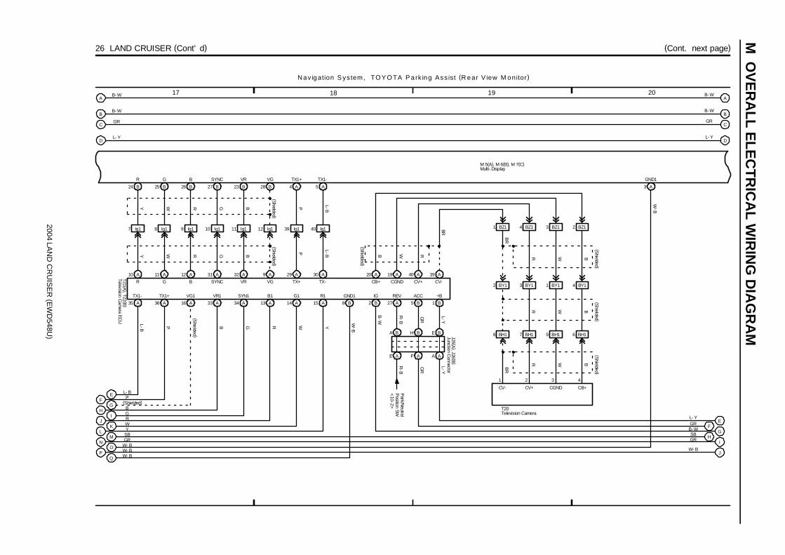
2004 LAN
D C
RU
ISE
R (E
WD
548U)
M O
VE
RA
LL ELE
CT
RIC
AL W
IRIN
G D
IAG
RA
M
17 18 19 20
26 LAND CRUISER (Cont’ d)
3 A
GND1
M 5(A), M 6(B), M 7(C)
A
NM
B- W
SBGR
Nav igation S ystem, TO Y O TA P ark ing Ass ist (R ear V iew M onitor)
PO W- B
W- B
Multi- Display
BB- W
CGR
DL- Y
LK W
Y
JI G
R
HG (Shielded)
B
FE L- B
P
35 A 36 A 16 A 33 A 34 A 13 A 14 A 15 A
10 A 11 A 12 A 31 A 32 A 9 A 29 A 30 A
24 B 25 B 26 B 27 B 23 B 28 B 4 A 5 A
7 Ig1 8 Ig1 9 Ig1 10 Ig1 11 Ig1 12 Ig1 39 Ig1 40 Ig1
8 B
Q W- B
1 B5 B27 A
A AF AE A
2 B
E BH BA B
L-Y
GR
R-B
B-W
R-B
GR
L-Y
L-B P B G R W Y
W-B
L-BPP L-B
BGRWYY W R G B
(Cont. next page)
A
B
C
D
EF
GH
I
J
20 A 19 A 40 A 39 A
2 BY1 3 BY1 1 BY1 4 BY1
8 BH1 7 BH1 9 BH1 6 BH1
Television CameraT20
1 BZ1 4 BZ1 3 BZ1 2 BZ1BR
RWB R W B
BR
R W B
R W B
BR
(Shielded )
(Shielded )
(Shielded )
(Shielded )
4321
CB+CGNDCV+CV-
CV-CV+CGNDCB+TX-TX+
(Shielded )(S
hielded )
Television C
amera EC
UT21 (A
), T22 (B)
+BACCREVIGGND1R1G1B1SYN1VR1VG1TX1+TX1-
R G B SYNC VR VG TX1+ TX1-
Junction Connector
J25 (A), J26 (B
)
VGVRSYNCBGR
Park/N
eutralP
osition SW<
10-2>
W- B
GRSB
B- WGRL- Y
L- Y
GR
B- W
B- W
(Shielded )
W-B

2004 LAN
D C
RU
ISE
R (E
WD
548U)
M
23 242221
26 LAND CRUISER (Cont’ d)
J
Multiplex
Com
munication
System<
1-37>
P-B
4E
12 B
TX3-
P-B
11 B
TX3+
P-L
W- B
9 4A
5
Set Bolt of Cowl Side J/B RH
19 2E
2Q22
9
GR
ACC
8
L-W
BATT
12
GTX-
5
GTX+
2
B-W
IG
4 11
MPD2MPD1
IH
714
GND CG
W-B
BR
BR
3D9
SB
L- W
G 4
M 5(A), M 6(B), M 7(C)
A
IH
B- W
SBGR
N av iga tion S ys tem, TO Y O TA Park ing A ss ist (R ear V iew M on itor )
Gateway ECU
Multi- Display
4 Ic2 5 Ic2
P-L
BB- W
CGR
DL- Y
GF GR
B- W
E L- Y
11
B
4
MIN-
6
Overhead J/BO 5
MIC+MIC-TACC
WY-G
B
(Shielded )
6 IE2
BW
4 IE2
MIN+
Y-G
MACC
5 IE2 3 IE2
5 B
32
(Shielded )
B
SGND
B3
W-B
E B
A A
Set Bolt of Cowl Side J/B LH IF
2E10
W-B
Junction Connector
J 9 (A), J10 (B
)
2L11
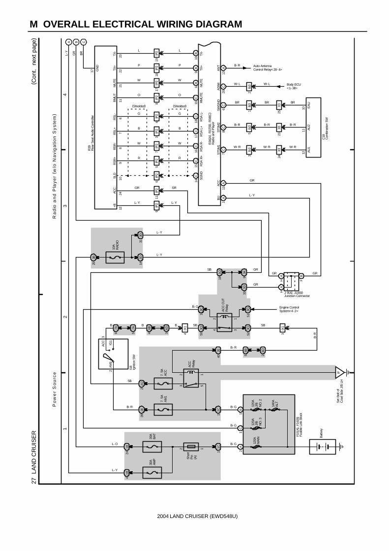
2004 LAND CRUISER (EWD548U)
M OVERALL ELECTRICAL WIRING DIAGRAM
12
34
27
LAN
D C
RU
ISE
R( C
ont.
nex
t pa
ge)
14C
15C
16C
17C
18C
6IP
25
IP2
7IP
23
IP2
4IP
28
IP2
19C
1110
98
76
R
W
B
G
O
R
W
B
G
O
SGN
DR
SA R
+R
SA
R-
RS
A L+
RSA
L-
RM
UTE
SLD
RSR
+R
SR
-R
SL+
RSL
-R
MU
T
R36
( A) ,
R37
( B) ,
R38
( C)
11IP
29
IP2
+BAC
C
1224
3D33
3Q18
GR
L- Y
GR
(Shielded) (Shielded)
R39
Ra
dio
an
d P
lay
er
( w/o
Na
vig
ati
on
Sy
ste
m)
Po
we
r S
ou
rce
AL-
Y
3K9
BG
R
7C
8C
6C
W- R
B- R
BR
AU
1AU
2E
AU
STS
M1
STSM
2SW
GN
D
1211
10
C18
BU A
1
ACC
A11GR
L- Y
SB
L- Y
GR
2221 6
B9
B10
B
17IP
218
IP2
19IP
2
W
P
L
W
P
L
23
MU
TETX
+TX
-
MU
TETX
+TX
-
GN
D
17
CB
R
AN
T B- R
A13
2A
1B
F15(
A), F
16( B
)
120A
MAI
N
120A
J/B
NO
. 2
Bat
tery
2
AC
C
IG1
AM
1
3
1C1
30A
BAT
1B24
30A
AMP
1B4
7. 5
AA
M1
2E39
2C1
12
53
IFS
et B
olt o
fC
owl S
ide
J/B
LH
7. 5
AAC
C
2E40
6B5
6D2
3IX
1
34
12
3Q52
6B4
6D3
3Q504
IX1
3C1
10A
RAD
IO
3B25
3D31
3D14
L- Y
L- Y
HA
HA
FB
3Ib
35
Ib3
1Ib
3
24II3
23II3
25II3
W- R
B- R
BR
W- R
B- R
BR
Sho
rtP
in( A
)
B- G
B- G
I18
2Q2
Engine ControlSystem<4- 2>
B SB
AC
CR
elay
B- R
SB
AC
C C
UT
Rel
ay
J 9(A), J10(B)
GRGRGR
L- Y
L- O
B- R
SB
B-R
140A
ALT
3Q51
120A
J/B
NO
. 3
C1
B- G
B- G
Auto AntennaControl Relay<28- 4>
Com
bina
tion
SW
Igni
tion
SW
Rad
io a
nd P
laye
r
Junction Connector
Rea
r S
eat A
udio
Con
trolle
r
Fusi
ble
Link
Blo
ck
B
12
AD
IM W- L
C20 2
Ib3W- L Body ECU
<1- 38>
7A6
7A5
B

2004 LAN
D C
RU
ISE
R (E
WD
548U)
M
5 6 7 8
27 LAND CRUISER (Cont’ d)
8 A 9 A 19 A
1 IP2
BR
BR
FR FL RL
R36(A), R37(B), R38(C)
A
B
L- Y
GR
21
2 IY2 IY21
LG L
LG LVP
VP
1 IC2IC22
1 2
F 9F 8
P V LG L
CBR
3 A
AMP
12 B 13 B
1 B
7 A
MUTE
18 Ig1 17 Ig1 19 Ig1 16 Ig1 22 Ig1
6 B
37 Ig1
6 A 15 A 5 A 14 A
3 IV3 4 IV3 1 IV3 2 IV3
2 A 9 A 1 A 8 A 13 A 12 A
BLRear Side Under theFront Passenger’ s Seat
2 4 1 3
W 4
WF+ WF- WF+ WF-
FR-FR+FL-FL+ EGND2AMP+
MUTE R. L F. R WFL+ WFL- WFR+ WFR-
S 6(A), S 7(B)
LLGVP
B-R
B-R
BR
BR
BR
L-W
L-Y
L-B
L-R
O W P Y
(Shielded )
(Shielded )
OWPY
R ad io and P laye r (w /o Nav igation S ystem)
BR
36 II4
21
3 BA3 BA32
B Y
R19
B Y
31 IV4 32 IV4
4 A 11 A
Y
RL-RL+
B
1 2
R
RR+ RR-
W
A10A3
R20
YB
2 BC3BC33
2 1
T13
2 1
T14
P V LG L
37 ID4 38 ID4
B Y
7 A
+B+B2
A162 B
ACC
16 IV3
2 Id2
5 IG1
L-Y
L-Y
L-Y
GR
L-YL-Y
L-Y
L-W
L-Y
L-B
L-RL-R
L-B
L-Y
L-W
33 IV4 34 IV4 35 IV4 36 IV4
41 ID4 42 ID4 39 ID4 40 ID4
20 Ig1 15 Ig1 21 Ig1 42 Ig1
14 B
R. R
5 B
F. L
4 B
BEEP
10 B
GND
11 B
SGND
20 A
GND
16 A
SLD
17 A
BEEP
18 A
RR
R G B BR B G RBR
BR
OWPY R G B
Front DoorSpeaker LH
Front DoorSpeaker RH
Radio and Player
Rear DoorSpeaker LH
Rear DoorSpeaker RH
Stereo Component Amplifier
Tweeter LH Tweeter RH
Woofer (Speaker)

2004 LAND CRUISER (EWD548U)
M OVERALL ELECTRICAL WIRING DIAGRAM
12
34
28
LAN
D C
RU
ISE
R
2
AC
C
IG1
ST1
AM1
3
B-R 12
53
7. 5
AA
CC
2D17
2E39
7. 5A AM1
2C1
IFSe
t Bol
t of
Cow
l Sid
e J/
B L
H
1B
6B4
6D3
3Q50
34
122E
40
6B5
6D2
3IX
1
3Q52
IIS
et B
olt o
fC
owl S
ide
J/B
RH
B- G
B- R
SB
B- R
GR
B
B-R
I18
F15(
A) ,
F16(
B) ,
F17(
C)
120A
J/B
NO
. 2
140A
ALT
Bat
tery
4IX
1 SB
ACC Relay
Engine ControlSystem<4- 2>
ACC CUTRelay
4L-
BB
Po
we
r S
ou
rce
Au
to A
nte
nn
a
1C
12
35
2E37
2Q77
3Q39
3C1
10A ECU- IG2
3D24
120A
J/B
NO
. 3
SB
B- G
B- W
B- G
10A
RA
DIO
293D
4Ib
1
IW3
4
6DO
WN
GN
D
ANTD
ANTU
L- W
UP
L- Y
W- B
53
9IW
3
19
ESU
P
IW3
10
12VCC
IW3
12
10SIG
IW3
11
11SG
ND
IW3
13
AA
54
12
63
A
IISe
t Bol
t of
Cow
l Sid
e J/
B R
H
3B2
16
144
717
SD
WN
W- B
W- B
B
W
R
(Shielded)
L- W
L- Y
B
W
R
(Shielded)
L- W
L- Y
B- R
L- Y
B- W
GR
L- YB
AC
CIG
BAN
TRadio and Player<26- 8><27- 4>
W- B
3B25
28A
29A
12C
IG1 NO. 3Relay
2A
120A
MA
IN30A BAT
1C1
1B24
Short Pin(A)
B- GL- O
5Ib
1
4D15
4B10
GR
J16
A45
( A) ,
A47
( C)
9Ib
110
Ib1
L- Y
L- W
2D2
2D22
IFSe
t Bol
t of
Cow
l Sid
e J/
B L
H
4B8
4D8
W- B
W- B
A30
AAJ1
1
W- B
A17
2E18
3N7
3P1
W- B
1514
W- B
C28
L- Y
L- W
(*2)
(*2)
(*1)
(*1)
(*1)
(*2)
(*1)
(*2)
513Q
2 1
* 1
: w/ N
avig
atio
n S
yste
m*
2 : w
/o N
avig
atio
n Sy
stem
S-A
NTU
S-A
NTD
GN
D
M
B- R
4E11
4B9
Auto
Ant
enna
Mot
or
Aut
o A
nten
na C
ontro
l Rel
ay
Igni
tion
SW
JunctionConnector
A/C
Con
trol
Ass
embl
y
Junc
tion
Con
nect
or
Cen
ter C
lust
erIn
tegr
atio
nPa
nel
Fusi
ble
Link
Blo
ck
A
B
57A
67A

2004 LAN
D C
RU
ISE
R (E
WD
548U)
M
1 2 3 4
29 LAND CRUISER
10AECU- B1
2C1
2D21 2E39
Battery
1
2
5
3
ACCRelay
1
2
5
3
10AECU- IG1
2D16 2E37
2E40
7. 5AACC
2Q2
IG1NO. 2Relay
B-G B
-R
B-R
IF Set Bolt ofCowl Side J/B LH
6B5
6D2
2
ACC
IG1AM1
3
4
6B4
6D3
3
4
1
2
3Q50 3C1
3Q52
3 IX1
4 IX1
ACC CUTRelay
SBS
BB
L-B
B
L- B
B- R
I18
Engine C
ontrolS
ystem<
4-2>
7. 5AAM1
120AJ/B NO. 2
140AALT
F16(B), F17(C)
B- R
4E3
H A
F B 4E7
J 9(A), J10(B)
3D33
4D114D10
3Q18
11 10 9
M ulti- D isplay (w /o N aviga tion S ystem)P ow er S ource
L-W
SB
B-W
B-W
GR
L-W
GR
L-W
B-W
SB
IG ACC +B
4 Ie1 3 Ie1
6 IU4 7 IU4
G-B
G-W
G-W
G-B
SBSB
UART-UART+
1 2
C14
II Set Bolt ofCowl SideJ/B RH
3D103D8
GND
8
W-B
W-B
W-B
TC
3
W-L
M 9
J10(B)
Body ECU
<1-38>
120AJ/B NO. 3
1 C 16 B
B-G
B-G
51 3Q
17 16
14
SECURITY A/C TEMP
P-L
Multiplex
Com
munication
System<
1-17>
A/C
Control
Assem
bly<31-13>
Combination Meter
Ignition SW
Multi- Display
JunctionConnector
JunctionConnector
Fusible LinkBlock
16
H B
H B
HB
B
6 7A
7A5
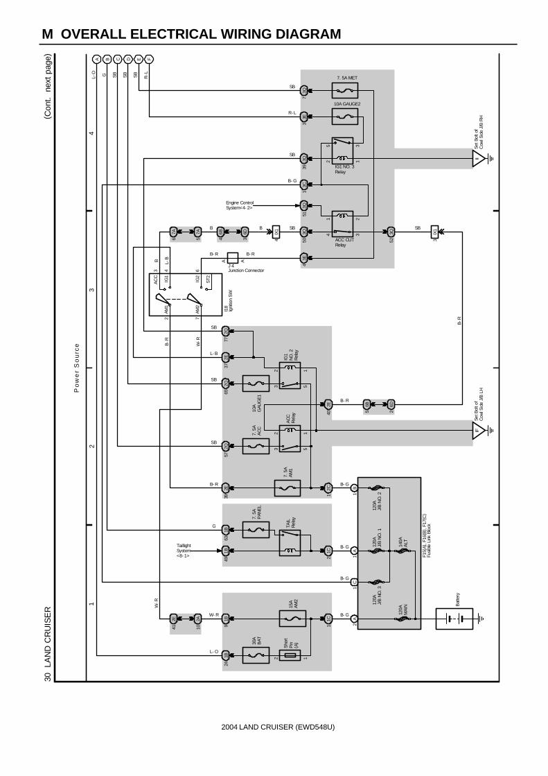
2004 LAND CRUISER (EWD548U)
M OVERALL ELECTRICAL WIRING DIAGRAM
12
34
30
LAN
D C
RU
ISE
R( C
ont.
nex
t pa
ge)
30A
BAT
1B24
1B9
15A
AM
2
1C1
2E41
2A10
2A
1C
1A
1B
7. 5
AP
ANE
L
1B63
1B49
1C2
7. 5
AA
M1
2C1
2E39
12
53
12
53
2E40
IFSe
t Bol
t of
Cow
l Sid
e J/
B L
H
7. 5
AA
CC
2Q57
10A
GAU
GE1
2Q65
2E37
2Q77
2 7
AC
C
IG1
IG2
ST2
AM1
3 4 6AM
2
6B5
6D2
6B4
6D3 4
IX1
AA 3E4
3Q50
3Q51
34
212
35
3Q39
3C1
10A GAUGE2
7. 5A MET
3E3
3Q7
IIS
et B
olt o
fC
owl S
ide
J/B
RH
3Q52 3
IX1
Sho
rtP
in( A
)
Bat
tery
B- G
B- G
B- G
B- G
TAIL
Rel
ay
L- O
W- R
TaillightSystem<8- 1>
B- R
L- B
SB
B- R
I18
B- R
SBB
IG1 NO. 3Relay
ACC CUTRelay
SB
B-R
SB
B- G
B-R
W-R
AC
CR
elay
IG1
NO
. 2R
elay
F15(
A), F
16( B
) , F1
7(C
)
W-R
A B C D E F
L-O G SB
SB
SB
R-L
R- L
SB
SB
SB
B- R
G
Engine ControlSystem<4- 2>
120A
MAI
N
120A
J/B
NO
. 112
0AJ/
B N
O. 3
120A
J/B
NO
. 2
Po
we
r S
ou
rce
140A
ALT
J 4
B L-B
12
1
Igni
tion
SW
Junction Connector
Fusi
ble
Link
Blo
ck
B
7A6
7A5

2004 LAN
D C
RU
ISE
R (E
WD
548U)
M
5 6 7 8
30 LAND CRUISER (Cont’ d) (Cont. next page)
Comb ina tion M e te r
Seat Belt
P R N
VoltTachom
eter
Fuel
Temp.
Oil
Speedom
eter
Buzzer
12 D 11 D 13 D
1 D15 D
EC Rear Bank ofRight CylinderHead
4 D 6 D 2 D16 D
10 A
A
B
C
D
E
F
6 Ib2
14 IN2
11 EB1
8 IX16 IX1
SB
SB
R-G
BR
F12
2Q63 2Q62 2Q61
2K19 2K21 2K13
1 BB1 6 BB15 BB1
SB
Y-BY-B
2
SB
Y-R
Y-R
1
SB
Y-GY-G
3
10A E
CU
-B2
10A D
OM
E
3B25
3Q453Q44
D 4 3 2
9 D
A
B
Multiplex C
omm
unicationSystem
<1-33>
L- O
G
SB
SB
SB
R- L
SB
G
R-L
R-L
R-L
R-L
SB
SB
SB
SB
SB
SB
L-O
C12(A), C13(B), C14(C), C15(D)
A
AJ14
SB
Combination Meter
Fuel Sender
JunctionConnector
Vehicle Speed Sensor(Combination Meter)
V 2
1
3
BR
R-G
702Q
433Q
282E
302D
113D
323K
B
B
SB
SB
V
V
V
V
SB
SB
Engine ControlModule<4- 16>
A/C ControlAssembly<31- 14>
Multi- Display<26- 14>
Navigation ECU<26- 14>
B
J14JunctionConnector
2
10 EB19 EB1
R-G
BR
BR
14
SPD
BodyECU

2004 LAN
D C
RU
ISE
R (E
WD
548U)
M O
VE
RA
LL ELE
CT
RIC
AL W
IRIN
G D
IAG
RA
M
11 12109
(Cont. next page)30 LAND CRUISER (Cont’ d)
Comb ina tion M e te r
L
A/T P
CR
UIS
E
2nd STR
T
EC
T PW
R
SRS
Fuel
Charge
A/T O
ILTEM
P
11 C 7 C20 D 19 D 7 D 4 C 17 C 16 C 10 D
Door
Beam
14 D 5 A8 B
3 A 7 A
G
SB
B
A
2B11
2Q83
SB
G
Multiplex
Com
munication
System
<1-35>
Seat Belt Warning
System<
25-3>
E
E
9 IX2
EC Rear Bank of RightCylinder Head
D
D
SB
SB
W
BR
J12
J17
O 2
SB
Multiplex
Com
munication
System<
1-34>
Multiplex
Com
munication
System
<1-34>
Multi-D
isplayS
ystem<
29-3>
SRS
System<
13-1>
(Shielded )
Illumination
System
<9-5>
Oil P
ressureS
ender
JunctionConnector
JunctionConnector
Combination MeterC12(A), C13(B), C14(C), C15(D)
1
MAIN
TR
EQ
D
Heat W
ire

2004 LAN
D C
RU
ISE
R (E
WD
548U)
M
15 161413
30 LAND CRUISER (Cont’ d)
Combina tion M ete r
Turn RH
Turn LH Malfunction
Indicator Lamp
VSC
OFF
Center D
iff. Lock
TRA
C
AB
S
BR
AKE
14 B 11 B 17 B 16 B 15 B 18 B 12 A 19 C 20 C 1 C 9 B
6 A 4 A
18 C
VSC
TRA
C
Slip R
SC
A O
FF
19 B
Turn Signal
and Hazard
Warning Light
System<
6-2>
C12(A), C13(B), C14(C), C15(D)
Multiplex C
omm
unicationS
ystem<
1-35>
VSC
System
<12-13>
<12-14>
Center D
ifferentialLock S
ystem<
14-3>
Engine Control S
ystem<
4-10>
2 IU2
B
B
IF Set Bolt ofCowl Side J/B LH
2E34
SB
W-B
W-B
J 8
SRS System
<13-2>
Combination Meter
JunctionConnector

2004 LAND CRUISER (EWD548U)
M OVERALL ELECTRICAL WIRING DIAGRAM
12
34
31
LAN
D C
RU
ISE
R( C
ont.
nex
t pa
ge)
1B24
1C1
1C
1A
1B
2A
7. 5
AAM
1
2C1
2E39
120A
J/B
NO
. 1
140A
ALT
120A
MA
IN
120A
J/B
NO
. 2
30A
BA
T
Batte
ry
12
53
15A
A/C
2D25
2E37
2Q77
10A GAUGE1
2D19
IG1
NO
. 2R
elay
B- G
B- G
B- G
B- G
L- O
B- R
IFS
et B
olt o
f Cow
l Sid
eJ/
B L
H
2
AC
C
IG1
AM
14
12
35
IG1 NO. 3Relay
10A ECU- IG2
3Q39
3C1
IIS
et B
olt o
f Cow
l Sid
eJ/
B R
H
F15(
A), F
16( B
) , F1
7(C
) , F1
8(D
)
I18
Shor
tPi
n( A
)
120A
J/B
NO
. 3
50A
HTR1
D
2A7
2B3
3B25
10A
EC
U-B
2
3K19
3Q71
A B D E F G H I J N O
Y-R
W-R
W-B
( *1)
W-B
R-L
R-L
R-L
R-L
L-B
L-W
SB
SB
L- W
L- B
L- B
L- B
SB
B- G
Po
we
r S
ou
rce
2IG
51
11
4
1 2
5 3
1B26
1B8
1
1B16
1 EA
Fron
t Rig
ht S
ide
ofFe
nder
Apr
on
1B56
1A43
1A34
213
W- B W- B
L- RL- B
R- L
R- L
HTR Relay
MG CLTRelay
B 1
ML
30A RR A/C
3K39
3K35
3K42
3H2
RB-
W
QB-
W
PLG
232D
22D
SB
182E
KW
-B
W- B
B-YL
L- R
Y- R
W- B
W- B
R- L
W- B
W- B
R- L
R- L
R- L
R-L
(*1)
CB-
G
W-B
LG
B- W
B- W
W- B
* 1
: w/ N
avig
atio
n S
yste
m
2 1
Blow
er M
otor
Con
trolle
r
Igni
tion
SW
Fusi
ble
Link
Blo
ck
62D
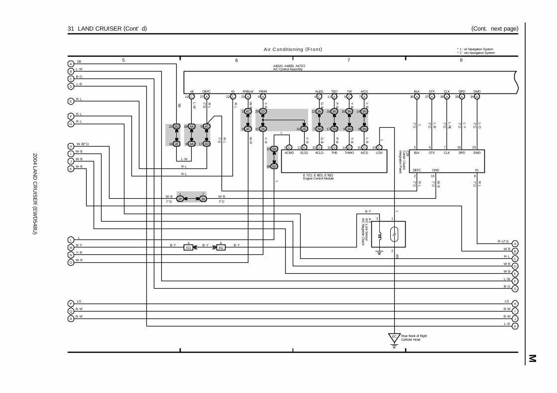
2004 LAN
D C
RU
ISE
R (E
WD
548U)
M
7 865
(Cont. next page)31 LAND CRUISER (Cont’ d)
27 A
4C5
4D17
DEFC+B
19 2E
22 2Q
9 4A
18 4A
C11 22 C
IG
9 A
2D29
2A15
FRHR
2D33
14 D13 E 33 D 32 D 31 D
4 C
3N12
3M7
ALED
11 A
3N18
3M17
TEO
5 C
3N16
3M9
TW
7 A
3N14
3M8
A/CS
23 A
4C1
4F9
FRBLW
D25A10
5D39
IN26
IG14
EC Rear Bank of RightCylinder Head
23 C
A
B
D
E
F
G
H
I
J
B
C
D
E
F
G
H
I
J
K
W- B
W- B
W- B(*1)
R- L
R- L
R- L
B- G
L- B
L- W
SB
L
LG
SB
L-W
R-L
R-L
W-R
Y-R
G-B
P-B
Y-B
L-B
Y-R
G-B
P-B
Y-B
L-B L
L
W- B
R- L
W- B
W- B
L- W
B- G
LG
B- W
B- W
L- B
3 1
2
L- W
R- L
R- L
Y-R
W-R
B- Y
B- Y
L
ACMG ELS2 ACLD THE THWO A/CS LCKI
A 5
BR
E 7(C), E 8(D), E 9(E)
A45(A), A46(B), A47(C)
A ir C onditioning (Fron t)
R
Q
P
O
N
M
L
K
38 A
BLK
37 A
STX
36 A
CLK
35 A
DPD
34 A
SWD
13P
73N
L L-B
L-R[
L-Y
L-O(*1 )
(*1 )
(*1 )
(*1 )
(*1 )
5 6 7 18 19
2 16 8
BLK STX CLK DPD SWD
DEFC GND IG
C28
L
R-L
W-B
R-L
(*1 )
(*1 )
(*1 )
R-L
(*1 )
W- B(*1)
B- YB- YB- Y
Y- R
W- R
B- W
B- W
W- B
W- B(*1)
AR- L(*1)
C
(*2 )
* 2 : w/o Navigation System* 1 : w/ Navigation System
A/C Lock S
ensorA/C
Magnetic C
lutch
Engine Control Module
A/C Control Assembly
Center C
lusterIntegration P
anel
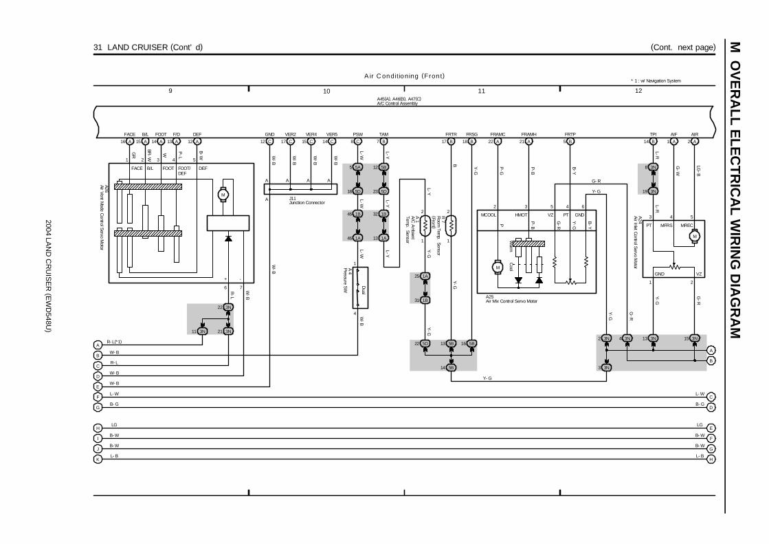
2004 LAN
D C
RU
ISE
R (E
WD
548U)
M O
VE
RA
LL ELE
CT
RIC
AL W
IRIN
G D
IAG
RA
M31 LAND CRUISER (Cont’ d) (Cont. next page)
9 10 1211
C 17 C 15 C 14 C
GND VER2 VER4 VER5
A
A A A A
16 A 15 A 14 A 13 A 12 A
FACE B/L FOOT F/D DEF
3N22
3N21
1
2
1
2
7 B 17 B 18 B
5D22 5B13 5B16
5B14
1B31
1A25
TAM FRTR FRSG
5 B21 A22 A
FRTPFRAMHFRAMC
14 B 1 A 2 A
TPI AIF AIR
3N2 3N4 3N13 3N15
3N8
3N19
3N3
5A5
5D18
1B46
1A46
4
1
8 C
PSW
B
C
D
E
F
G
H
I
J
K
C
D
E
F
G
H
W- B
R- L
W- B
W- B
L- W
B- G
LG
B- W
B- W
L- B
L-W
A45(A), A46(B), A47(C)
L-W
GR
BR-W
W P-L
B-W W-B
W-B
W-B
W-B
L-WW
-B
R-L
W-B
W-B
L-YY
-GY
-G
Y-GB Y
-G
B-Y
P-B
P-G
L-RL-R
G-W
LG-B
G-R
Y-G
G-R
Y-G
L- W
B- G
LG
B- W
B- W
L- B
1 2 3 4 5
6 7
A26
J11
A 4
A 1
R 7
1 2
432
3 4 5
A25
A24
A ir C onditioning (Fron t)
A
B
5B12
5D23
1B32
1A13
L-YL-Y
L-Y
* 1 : w/ Navigation System
Y- G
Dual
3N11
AR- L(*1)
M
FACE B/L FOOT FOOT/DEF
DEF
-+
Warm
CoolM
5 6
G- R
Y- G
B-Y
Y-G
G-R
P-BP
GNDPTVZHMOTMCOOL
12
A/C
Am
bientTem
p. Sensor
Pressure SW
Air Inlet C
ontrol Servo M
otor
Air Mix Control Servo Motor
Air Vent Mode C
ontrol Servo M
otor
Room
Temp. Sensor
(Front )
A/C Control Assembly
Junction Connector
M
GND VZ
PT MFRS MREC
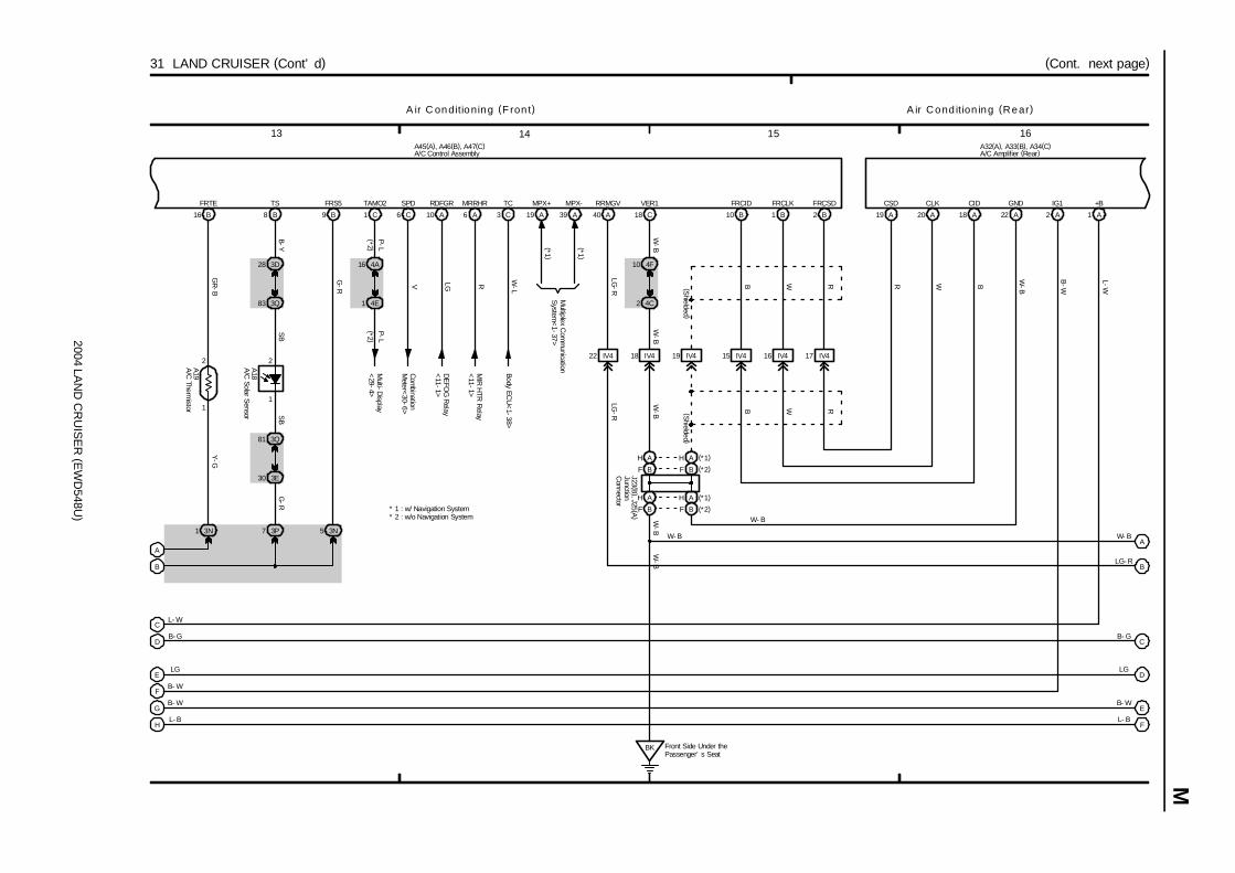
2004 LAN
D C
RU
ISE
R (E
WD
548U)
M
15 161413
(Cont. next page)31 LAND CRUISER (Cont’ d)
1
2
16 B
FRTE
3N1
1
2
8 B
TS
3D28
3Q83
3Q81
3E30
3P7
9 B
FRS5
3N5
1 C 6 C 10 A 6 A
TAMO2 SPD RDFGR MRRHR
4A16
4E1
Com
binationM
eter<30-6>
Multi-D
isplay<
29-4>
DE
FOG
Relay
<11-1>
MIR
HTR
Relay
<11-1>
40 A 18 C 10 B 1 B 2 B
4F10
4C2
17 IV416 IV415 IV419 IV418 IV422 IV4
19 A 20 A 18 A 22 A
BK Front Side Under thePassenger’ s Seat
RRMGV VER1 FRCID FRCLK FRCSD CSD CLK CID GND
2 A 1 A
IG1 +B
C
D
E
F
G
H
A
B
C
D
E
F
L- W
B- G
LG
B- W
B- W
L- B
A45(A), A46(B), A47(C)
B-Y
A32(A), A33(B), A34(C)
P-L
V LG R
G-R
GR
-B
SB
SB
G-R
Y-G
P-L
W-B
LG-R
B W R
(Shielded )
RWB
W-B
LG-R
R W B
W-B
B-W
L-W
W-B
W-B
W- B
LG- R
B- G
LG
B- W
L- B
W- B
W- B
A19
A18
W-B
(Shielded )
A ir Cond ition ing (Rear)A ir C onditioning (F ron t)
A
B
(*2 )(*2 )
3 C
TC
* 2 : w/o Navigation System
Body ECU
<1-38>
W-L
A/C
Solar Sensor
A/C
Thermistor
A/C Amplifier (Rear)A/C Control Assembly
19 A
MPX+
39 A
MPX-
Multiplex C
omm
unicationS
ystem<
1-37>(*1 )
(*1 )
* 1 : w/ Navigation System
F B
H A
F B (*2)
H A (*1)
H A (*1)
F B (*2)
H A
F B
JunctionC
onnector
J23 (B), J25 (A
)
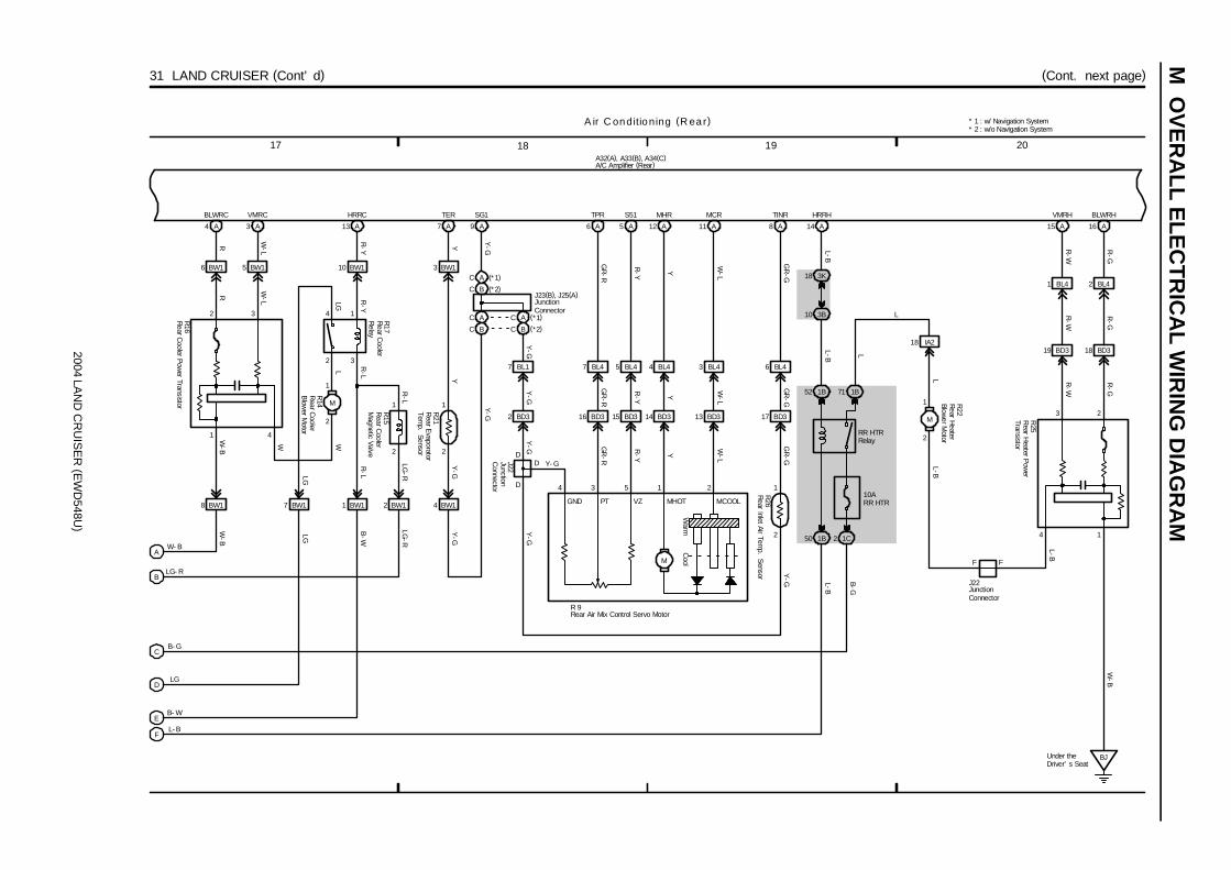
2004 LAN
D C
RU
ISE
R (E
WD
548U)
M O
VE
RA
LL ELE
CT
RIC
AL W
IRIN
G D
IAG
RA
M
19 201817
(Cont. next page)31 LAND CRUISER (Cont’ d)
4 A 3 A 13 A 7 A
6 BW1 5 BW1 10 BW1 3 BW1
1 BW1 2 BW18 BW1 4 BW1
9 A 8 A
2 BD3 13 BD314 BD3
7 BL1 3 BL44 BL4
11 AA12
D
D
2
1
17 BD3
6 BL4
D
10ARR HTR
1C21B50
1B52 1B71
A14
HRRH
3K18
3B10
2
1
M
18 IA219 BD3 18 BD3
1 BL4 BL42
A15 16 A
7 BW1
A
B
C
D
E
F
W- B
LG- R
B- G
LG
B- W
L- B
A ir C onditioning (R ear)
L-B
R W-L
R-Y Y
Y-G
W-L
Y
GR
-GG
R-G
Y
W-L
Y-G
Y-G
W-B
LG-R
LG
B-W
Y-G
Y-G
Y-G W
-L
Y
GR
-GY
-G L-B
B-G
L-B L
LL-B
W-B
R-G
R-W
R-W
R-G
R-W
R-G
L
Y- G
1 2
3 2
1
BLWRC VMRC HRRC TER SG1 MCRMHR TINR VMRH BLWRH
J22
R 9
R26
RR HTRRelay
R22
A32(A), A33(B), A34(C)
2
1
3
1
2
4
2
1
M
2
1
LG-R
R-L
R-L
R-L
L
41
WW
LG
LG
R-Y
W-B
2 3
R
W-L
Y-G
Y
R21
R15
R14
R16
R17
Cool
Warm
M
16 BD3 15 BD3
7 BL4 BL45
6 A 5 A
GR
-R
R-Y
R-Y
GR
-RG
R-R
R-Y
34 5
TPR S51
GND PT VZ MHOT MCOOL
A/C Amplifier (Rear)
Rear Air Mix Control Servo Motor
Rear C
oolerB
lower M
otor
Rear C
oolerM
agnetic Valve
Rear C
ooler Pow
er Transistor
Rear C
oolerR
elay
Rear E
vaporatorTem
p. Sensor
Rear H
eaterBlow
er Motor
Rear Inlet Air Tem
p. Sensor
JunctionC
onnector
BJUnder theDriver’ s Seat
4
L-B
Rear H
eater Pow
erTransistor
R25
F F
JunctionConnector
J22
C B (* 2)
C A (* 1)
C A (*1)
C B (*2)
C A
C B
JunctionConnector
J23(B), J25(A)
Y-G
* 1 : w/ Navigation System* 2 : w/o Navigation System

2004 LAN
D C
RU
ISE
R (E
WD
548U)
M
23 242221
31 LAND CRUISER (Cont’ d)
A ir C onditioning (R ear)
A32(A), A33(B), A34(C)
R 8
AU
TO
Foot
LO
Middle
AU
TO
OFF
LO
Middle
HI
Face
Bi-Level
Foot
HI
Face
Bi-Level
12 B
SG2
7 B
TRR
2
1
20
B
G-Y
G-Y
G-Y
4 B
S52
8 B
TSETR
2221
L-O
Y-R
L-O
Y-R
6 C
LO- I
6
L-WL-W
5 C
AUTO- I
7
L-RL-R
16 C
B/L- I
17 C
FOOT- I
7 C
ME- I
18 C
HI- I
15 C
FACE- I
2 15 4 3
W-G
W-R
L L GGLL
W-R
W-G
1 B
IG2
5 B
ILL+2
9 8
GL-R
GL-R
8 C
RG
11 10
G-W
G-W
G-W
9 C
HI- S
4 C
ME- S
3 C
LO- S
2 C
OFF- S
1 C
AUTO- S
10 C
FACE- S
11 C
B/L- S
12 C
FOOT- S
15 16 17 18 19141312
GR
-R
L-Y
GR
Y-B
W-G
R-L
R-Y
R-G
R-G
R-Y
R-L
W-G
Y-B
GR
L-Y
GR
-R
SG T- SET S5 AUTO- I LO- I ME- I HI- I FACE- I B/L- I FOOT- I IG RG SRG FOOT- S B/L- S FACE- S HI- S ME- S LO- S OFF- S AUTO- SILL
R34
CoolHot
Illumination
A/C Amplifier (Rear)
Rear A/C Control SW
Room
Temp. S
ensor (Rear )

M OVERALL ELECTRICAL WIRING DIAGRAM
2004 LAND CRUISER (EWD548U)
410

M
2004 LAN
D C
RU
ISE
R (E
WD
548U)
411
[A] : System Title
[B] : Indicates the wiring color.
Wire colors are indicated by an alphabetical code.
B = Black W = White BR = Brown
L = Blue V = Violet SB = Sky Blue
R = Red G = Green LG = Light Green
P = Pink Y = Yellow GR = Gray
O = Orange
The first letter indicates the basic wire color and thesecond letter indicates the color of the stripe.Example: L - Y
L(Blue)
Y(Yellow)
[C] : The position of the parts is the same as shown inthe wiring diagram and wire routing.
[D] : Indicates the pin number of the connector.The numbering system is different for femaleand male connectors.Example : Numbered in order
from upper left tolower right
Numbered in orderfrom upper right tolower left
Female Male
The numbering system for the overall wiring diagram is the same as above
[E] : Indicates a Relay Block. No shading is used and only the Relay Block No. is shown to distinguishit from the J/B.Example : Indicates Relay Block No.1
[F] : Junction Block (The number in the circle is the J/B No. and the connector code is shown beside it). Junction Blocks are shaded to clearly separate them from other parts.
3C indicates thatit is insideJunction BlockNo.3
Example:
[G] : Indicates related system.
[H] : Indicates the wiring harness and wiring harnessconnector. The wiring harness with maleterminal is shown with arrows ( ).Outside numerals are pin numbers.
Female Male ( )
[I] : ( ) is used to indicate different wiring andconnector, etc. when the vehicle model, engine type, or specification is different.
[J] : Indicates a shielded cable.
[K] : Indicates and located on ground point.
[L] : The same code occuring on the next page indicates that the wire harness is continuous.

SYSTEM INDEXM
OV
ER
ALL E
LEC
TR
ICA
L WIR
ING
DIA
GR
AM
2004 LAN
D C
RU
ISE
R (E
WD
548U)
412
SYSTEMS LOCATION SYSTEMS LOCATIONAir Conditioning (Front) 31-5. . . . . . . . . . . . . . . . . . . . . . . . . . . . . . . . . . . . .
Air Conditioning (Rear) 31-15. . . . . . . . . . . . . . . . . . . . . . . . . . . . . . . . . . . .
Auto Antenna 28-3. . . . . . . . . . . . . . . . . . . . . . . . . . . . . . . . . . . . . . . . . . . . .
Automatic Glare-Resistant EC Mirror with Compass 15-3. . . . . . . . . . .
Back-Up Light 10-2. . . . . . . . . . . . . . . . . . . . . . . . . . . . . . . . . . . . . . . . . . . .
Center Differential Lock 14-3. . . . . . . . . . . . . . . . . . . . . . . . . . . . . . . . . . . .
Charging 2-4. . . . . . . . . . . . . . . . . . . . . . . . . . . . . . . . . . . . . . . . . . . . . . . . . . .
Cigarette Lighter 21-2. . . . . . . . . . . . . . . . . . . . . . . . . . . . . . . . . . . . . . . . . . .
Combination Meter 30-5. . . . . . . . . . . . . . . . . . . . . . . . . . . . . . . . . . . . . . . .
Cruise Control 5-5. . . . . . . . . . . . . . . . . . . . . . . . . . . . . . . . . . . . . . . . . . . . . . .
Electronically Controlled Transmission and A/T Indicator 5-6. . . . . . . . . .
Engine Control 4-4. . . . . . . . . . . . . . . . . . . . . . . . . . . . . . . . . . . . . . . . . . . . . .
Engine Immobiliser System 4-19. . . . . . . . . . . . . . . . . . . . . . . . . . . . . . . . .
Front Wiper and Washer 18-2. . . . . . . . . . . . . . . . . . . . . . . . . . . . . . . . . . . .
Garage Door Opener 15-4. . . . . . . . . . . . . . . . . . . . . . . . . . . . . . . . . . . . . . .
Horn 18-4. . . . . . . . . . . . . . . . . . . . . . . . . . . . . . . . . . . . . . . . . . . . . . . . . . . . .
Ignition 3-2. . . . . . . . . . . . . . . . . . . . . . . . . . . . . . . . . . . . . . . . . . . . . . . . . . . . .
Illumination 9-3. . . . . . . . . . . . . . . . . . . . . . . . . . . . . . . . . . . . . . . . . . . . . . . . .
Mirror Heater 11-3. . . . . . . . . . . . . . . . . . . . . . . . . . . . . . . . . . . . . . . . . . . . . .
Moon Roof 17-2. . . . . . . . . . . . . . . . . . . . . . . . . . . . . . . . . . . . . . . . . . . . . . .
Multi-Display (w/o Navigation System) 29-3. . . . . . . . . . . . . . . . . . . . . . .
Multiplex Communication System 1-5. . . . . . . . . . . . . . . . . . . . . . . . . . . . . . ∗ Automatic Light Control∗ Door Lock Control∗ Front Fog Light∗ Headlight∗ Interior Light∗ Key Reminder
∗ Light Auto Turn Off∗ Power Window∗ Theft Deterrent∗ Wireless Door Lock Control
Navigation System 26-12. . . . . . . . . . . . . . . . . . . . . . . . . . . . . . . . . . . . . . . .
Power Outlet 20-2. . . . . . . . . . . . . . . . . . . . . . . . . . . . . . . . . . . . . . . . . . . . . .
Power Rear Quarter Window 11-4. . . . . . . . . . . . . . . . . . . . . . . . . . . . . . . . .
Power Seat 22-2. . . . . . . . . . . . . . . . . . . . . . . . . . . . . . . . . . . . . . . . . . . . . . .
Power Source 1~31-1. . . . . . . . . . . . . . . . . . . . . . . . . . . . . . . . . . . . . . . . . . .
Power Tilt and Power Telescopic 23-2. . . . . . . . . . . . . . . . . . . . . . . . . . . . .
Radio and Player (w/ Navigation System) 26-5. . . . . . . . . . . . . . . . . . . . .
Radio and Player (w/o Navigation System) 27-3. . . . . . . . . . . . . . . . . . . .
Rear Window Defogger 11-2. . . . . . . . . . . . . . . . . . . . . . . . . . . . . . . . . . . . . .
Rear Wiper and Washer 19-2. . . . . . . . . . . . . . . . . . . . . . . . . . . . . . . . . . . .
Remote Control Mirror 16-2. . . . . . . . . . . . . . . . . . . . . . . . . . . . . . . . . . . . . .
Seat Belt Warning 25-2. . . . . . . . . . . . . . . . . . . . . . . . . . . . . . . . . . . . . . . . .
Seat Heater 21-3. . . . . . . . . . . . . . . . . . . . . . . . . . . . . . . . . . . . . . . . . . . . . . .
Shift Lock 24-3. . . . . . . . . . . . . . . . . . . . . . . . . . . . . . . . . . . . . . . . . . . . . . . .
SRS 13-2. . . . . . . . . . . . . . . . . . . . . . . . . . . . . . . . . . . . . . . . . . . . . . . . . . . . .
Starting 2-2. . . . . . . . . . . . . . . . . . . . . . . . . . . . . . . . . . . . . . . . . . . . . . . . . . . .
Stop Light 10-3. . . . . . . . . . . . . . . . . . . . . . . . . . . . . . . . . . . . . . . . . . . . . . . .
Taillight 8-2. . . . . . . . . . . . . . . . . . . . . . . . . . . . . . . . . . . . . . . . . . . . . . . . . . . . .
TOYOTA Parking Assist (Rear View Monitor) 26-12. . . . . . . . . . . . . . . . .
Trailer Towing 7-2. . . . . . . . . . . . . . . . . . . . . . . . . . . . . . . . . . . . . . . . . . . . . . .
Turn Signal and Hazard Warning Light 6-2. . . . . . . . . . . . . . . . . . . . . . . . . .
VSC 12-4. . . . . . . . . . . . . . . . . . . . . . . . . . . . . . . . . . . . . . . . . . . . . . . . . . . . .
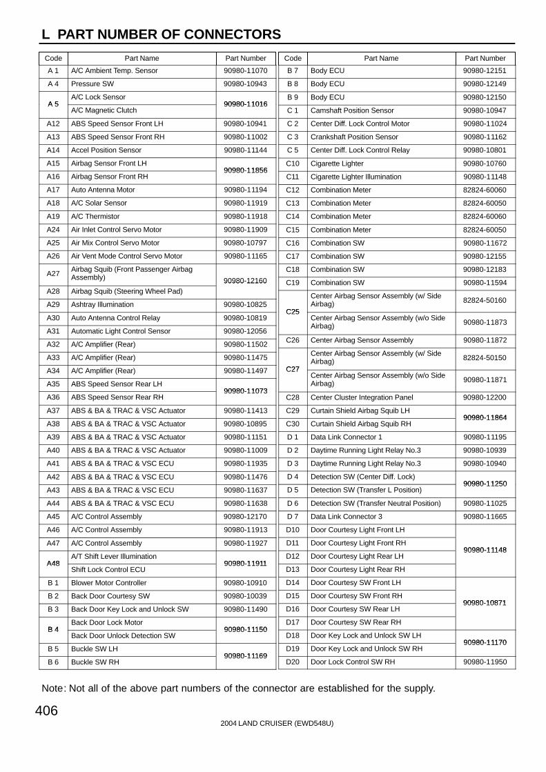
L PART NUMBER OF CONNECTORS
Code Part Name Part Number Code Part Name Part Number
Note: Not all of the above part numbers of the connector are established for the supply.
2004 LAND CRUISER (EWD548U)406
A 1 A/C Ambient Temp. Sensor 90980-11070
A 4 Pressure SW 90980-10943
A 5A/C Lock Sensor
90980-11016A 5A/C Magnetic Clutch
90980-11016
A12 ABS Speed Sensor Front LH 90980-10941
A13 ABS Speed Sensor Front RH 90980-11002
A14 Accel Position Sensor 90980-11144
A15 Airbag Sensor Front LH90980-11856
A16 Airbag Sensor Front RH90980-11856
A17 Auto Antenna Motor 90980-11194
A18 A/C Solar Sensor 90980-11919
A19 A/C Thermistor 90980-11918
A24 Air Inlet Control Servo Motor 90980-11909
A25 Air Mix Control Servo Motor 90980-10797
A26 Air Vent Mode Control Servo Motor 90980-11165
A27Airbag Squib (Front Passenger AirbagAssembly) 90980-12160
A28 Airbag Squib (Steering Wheel Pad)90980 12160
A29 Ashtray Illumination 90980-10825
A30 Auto Antenna Control Relay 90980-10819
A31 Automatic Light Control Sensor 90980-12056
A32 A/C Amplifier (Rear) 90980-11502
A33 A/C Amplifier (Rear) 90980-11475
A34 A/C Amplifier (Rear) 90980-11497
A35 ABS Speed Sensor Rear LH90980-11073
A36 ABS Speed Sensor Rear RH90980-11073
A37 ABS & BA & TRAC & VSC Actuator 90980-11413
A38 ABS & BA & TRAC & VSC Actuator 90980-10895
A39 ABS & BA & TRAC & VSC Actuator 90980-11151
A40 ABS & BA & TRAC & VSC Actuator 90980-11009
A41 ABS & BA & TRAC & VSC ECU 90980-11935
A42 ABS & BA & TRAC & VSC ECU 90980-11476
A43 ABS & BA & TRAC & VSC ECU 90980-11637
A44 ABS & BA & TRAC & VSC ECU 90980-11638
A45 A/C Control Assembly 90980-12170
A46 A/C Control Assembly 90980-11913
A47 A/C Control Assembly 90980-11927
A48A/T Shift Lever Illumination
90980-11911A48Shift Lock Control ECU
90980-11911
B 1 Blower Motor Controller 90980-10910
B 2 Back Door Courtesy SW 90980-10039
B 3 Back Door Key Lock and Unlock SW 90980-11490
B 4Back Door Lock Motor
90980-11150B 4Back Door Unlock Detection SW
90980-11150
B 5 Buckle SW LH90980-11169
B 6 Buckle SW RH90980-11169
B 7 Body ECU 90980-12151
B 8 Body ECU 90980-12149
B 9 Body ECU 90980-12150
C 1 Camshaft Position Sensor 90980-10947
C 2 Center Diff. Lock Control Motor 90980-11024
C 3 Crankshaft Position Sensor 90980-11162
C 5 Center Diff. Lock Control Relay 90980-10801
C10 Cigarette Lighter 90980-10760
C11 Cigarette Lighter Illumination 90980-11148
C12 Combination Meter 82824-60060
C13 Combination Meter 82824-60050
C14 Combination Meter 82824-60060
C15 Combination Meter 82824-60050
C16 Combination SW 90980-11672
C17 Combination SW 90980-12155
C18 Combination SW 90980-12183
C19 Combination SW 90980-11594
C25
Center Airbag Sensor Assembly (w/ SideAirbag) 82824-50160
C25Center Airbag Sensor Assembly (w/o SideAirbag) 90980-11873
C26 Center Airbag Sensor Assembly 90980-11872
C27
Center Airbag Sensor Assembly (w/ SideAirbag) 82824-50150
C27Center Airbag Sensor Assembly (w/o SideAirbag) 90980-11871
C28 Center Cluster Integration Panel 90980-12200
C29 Curtain Shield Airbag Squib LH90980-11864
C30 Curtain Shield Airbag Squib RH90980-11864
D 1 Data Link Connector 1 90980-11195
D 2 Daytime Running Light Relay No.3 90980-10939
D 3 Daytime Running Light Relay No.3 90980-10940
D 4 Detection SW (Center Diff. Lock)90980-11250
D 5 Detection SW (Transfer L Position)90980-11250
D 6 Detection SW (Transfer Neutral Position) 90980-11025
D 7 Data Link Connector 3 90980-11665
D10 Door Courtesy Light Front LH
D11 Door Courtesy Light Front RH90980-11148
D12 Door Courtesy Light Rear LH90980-11148
D13 Door Courtesy Light Rear RH
D14 Door Courtesy SW Front LH
D15 Door Courtesy SW Front RH90980-10871
D16 Door Courtesy SW Rear LH90980-10871
D17 Door Courtesy SW Rear RH
D18 Door Key Lock and Unlock SW LH90980-11170
D19 Door Key Lock and Unlock SW RH90980-11170
D20 Door Lock Control SW RH 90980-11950

L
Code Part Name Part Number Code Part Name Part Number
2004 LAND CRUISER (EWD548U)
407
D21Door Lock Motor Front LH
D21Door Unlock Detection SW Front LH
D22Door Lock Motor Front RH
D22Door Unlock Detection SW Front RH
90980-11150
D23Door Lock Motor Rear LH
90980-11150
D23Door Unlock Detection SW Rear LH
D24Door Lock Motor Rear RH
D24Door Unlock Detection SW Rear RH
D26 DVD Automatic Changer 90980-11971
D27 Door Control Receiver 90980-11909
E 1Electronically Controlled TransmissionSolenoid 90980-12293
E 2 Engine Coolant Temp. Sensor 90980-10736
E 3 Engine Hood Courtesy SW 90980-11003
E 4Electronically Controlled TransmissionPattern Select SW 90980-10933
E 5 Engine Control Module 90980-12144
E 6 Engine Control Module 90980-12145
E 7 Engine Control Module 90980-12143
E 8 Engine Control Module 90980-12146
E 9 Engine Control Module 90980-12142
F 1 Front Fog Light LH90980-11660
F 2 Front Fog Light RH90980-11660
F 3Front Turn Signal Light LH
F 3Side Marker Light LH
90980-11020
F 4Front Turn Signal Light RH
90980-11020
F 4Side Marker Light RH
F 5 Front Wiper Motor 90980-11599
F 8 Front Door Speaker LH90980-10935
F 9 Front Door Speaker RH90980-10935
F10Front Interior Light
90980-12211F10Rear Personal Light
90980-12211
F11 Front Personal Light 90980-10825
F12Fuel Pump
90980-11077F12Fuel Sender
90980-11077
F14 Fuel Pump Resistor 90980-11156
F15 Fusible Link Block 90980-11996
F16 Fusible Link Block 90980-11881
F17 Fusible Link Block 90980-11775
F18 Fusible Link Block 90980-10995
F19 Fusible Link Block 82675-60050
G 1 Generator 90980-11964
G 2 Generator 90980-09212
G 3 Glove Box Light 90980-11098
G 4 Gateway ECU 90980-11911
H 1 Headlight LH (High) 90980-11659
H 2 Headlight LH (Low) 90980-11660
H 3 Headlight RH (High) 90980-11659
H 4 Headlight RH (Low) 90980-11660
H 5 Heated Oxygen Sensor (Bank 1 Sensor 1) 90980-10869
H 6 Heated Oxygen Sensor (Bank 1 Sensor 2) 90980-11028
H 7 Heated Oxygen Sensor (Bank 2 Sensor 1) 90980-10869
H 8 Heated Oxygen Sensor (Bank 2 Sensor 2) 90980-11028
H 9 Horn LH90980-10619
H10 Horn RH90980-10619
H11 High Mounted Stop Light 90980-11211
I 1 Ignition Coil and Igniter No.1
I 2 Ignition Coil and Igniter No.2
I 3 Ignition Coil and Igniter No.3
I 4 Ignition Coil and Igniter No.490980-11885
I 5 Ignition Coil and Igniter No.590980-11885
I 6 Ignition Coil and Igniter No.6
I 7 Ignition Coil and Igniter No.7
I 8 Ignition Coil and Igniter No.8
I 9 Injector No.1
I10 Injector No.2
I11 Injector No.3
I12 Injector No.490980-11153
I13 Injector No.590980-11153
I14 Injector No.6
I15 Injector No.7
I16 Injector No.8
I18 Ignition SW 90980-11615
I22 Inner Mirror 90980-11186
J 1 Junction Connector 90980-11398
J 2 Junction Connector 90980-11915
J 3 Junction Connector90980-11398
J 4 Junction Connector90980-11398
J 5 Junction Connector 90980-11925
J 6 Junction Connector90980-11927
J 7 Junction Connector90980-11927
J 8 Junction Connector 90980-10803
J 9 Junction Connector90980-11927
J10 Junction Connector90980-11927
J11 Junction Connector 90980-10803
J12 Junction Connector 90980-11927
J13 Junction Connector 90980-11925
J14 Junction Connector 90980-11927
J15 Junction Connector 90980-11925
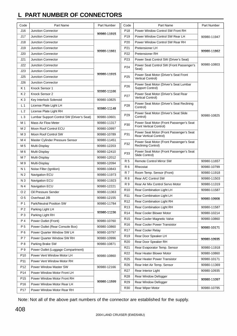
L PART NUMBER OF CONNECTORS
Code Part Name Part Number Code Part Name Part Number
Note: Not all of the above part numbers of the connector are established for the supply.
2004 LAND CRUISER (EWD548U)408
J16 Junction Connector90980-11915
J17 Junction Connector90980-11915
J18 Junction Connector
J19 Junction Connector90980-11661
J20 Junction Connector90980-11661
J21 Junction Connector
J22 Junction Connector
J23 Junction Connector90980-11915
J25 Junction Connector90980-11915
J26 Junction Connector
K 1 Knock Sensor 190980-11166
K 2 Knock Sensor 290980-11166
K 3 Key Interlock Solenoid 90980-10825
L 1 License Plate Light LH90980-11148
L 2 License Plate Light RH90980-11148
L 3 Lumbar Support Control SW (Driver’s Seat) 90980-10601
M 1 Mass Air Flow Meter 90980-11317
M 2 Moon Roof Control ECU 90980-10997
M 3 Moon Roof Control SW 90980-10789
M 4 Master Cylinder Pressure Sensor 90980-11451
M 5 Multi-Display 90980-12203
M 6 Multi-Display 90980-12410
M 7 Multi-Display 90980-12012
M 9 Multi-Display 90980-12094
N 1 Noise Filter (Ignition) 90980-10843
N 2 Navigation ECU 90980-11973
N 3 Navigation ECU 90980-11923
N 4 Navigation ECU 90980-12221
O 2 Oil Pressure Sender 90980-11363
O 5 Overhead J/B 90980-12155
P 1 Park/Neutral Position SW 90980-11784
P 2 Parking Light LH90980-11156
P 3 Parking Light RH90980-11156
P 4 Power Outlet (Front) 90980-10760
P 5 Power Outlet (Rear Console Box) 90980-10860
P 6 Power Quarter Window SW LH 90980-10797
P 7 Power Quarter Window SW RH 90980-10996
P 8 Parking Brake SW 90980-10871
P 9 Power Outlet (Luggage Compartment)
P10 Power Vent Window Motor LH 90980-10860
P11 Power Vent Window Motor RH
P12 Power Window Master SW 90980-12166
P14 Power Window Motor Front LH
P15 Power Window Motor Front RH90980-11599
P16 Power Window Motor Rear LH90980-11599
P17 Power Window Motor Rear RH
P18 Power Window Control SW Front RH
P19 Power Window Control SW Rear LH 90980-11947
P20 Power Window Control SW Rear RH
P21 Pretensioner LH90980-11862
P22 Pretensioner RH90980-11862
P23 Power Seat Control SW (Driver’s Seat)
P24Power Seat Control SW (Front Passenger’sSeat)
90980-10803
P25Power Seat Motor (Driver’s Seat FrontVertical Control)
P26Power Seat Motor (Driver’s Seat LumbarSupport Control)
P27Power Seat Motor (Driver’s Seat RearVertical Control)
P28Power Seat Motor (Driver’s Seat RecliningControl)
P29Power Seat Motor (Driver’s Seat SlideControl) 90980-10825
P30Power Seat Motor (Front Passenger’s SeatFront Vertical Control)
P31Power Seat Motor (Front Passenger’s SeatRear Vertical Control)
P32Power Seat Motor (Front Passenger’s SeatReclining Control)
P33Power Seat Motor (Front Passenger’s SeatSlide Control)
R 5 Remote Control Mirror SW 90980-11657
R 6 Rheostat 90980-10799
R 7 Room Temp. Sensor (Front) 90980-11918
R 8 Rear A/C Control SW 90980-11503
R 9 Rear Air Mix Control Servo Motor 90980-11319
R10 Rear Combination Light LH 90980-11587
R11 Rear Combination Light LH90980-10908
R12 Rear Combination Light RH90980-10908
R13 Rear Combination Light RH 90980-11587
R14 Rear Cooler Blower Motor 90980-10214
R15 Rear Cooler Magnetic Valve 90980-10860
R16 Rear Cooler Power Transistor90980-10171
R17 Rear Cooler Relay90980-10171
R19 Rear Door Speaker LH90980-10935
R20 Rear Door Speaker RH90980-10935
R21 Rear Evaporator Temp. Sensor 90980-11918
R22 Rear Heater Blower Motor 90980-10860
R25 Rear Heater Power Transistor 90980-10171
R26 Rear Inlet Air Temp. Sensor 90980-11369
R27 Rear Interior Light 90980-10935
R28 Rear Window Defogger90980-11097
R29 Rear Window Defogger90980-11097
R30 Rear Wiper Motor 90980-10795

L
Code Part Name Part Number Code Part Name Part Number
2004 LAND CRUISER (EWD548U)
409
R31 Rear Wiper Relay 90980-10797
R32 Remote Control Mirror LH90980-11573
R33 Remote Control Mirror RH90980-11573
R34 Room Temp. Sensor (Rear) 90980-11918
R36 Radio and Player 90980-12038
R37 Radio and Player 90980-12183
R38 Radio and Player 90980-12259
R39 Rear Seat Audio Controller 90980-12200
R40Roll Sensing of Curtain Shield AirbagsCutoff SW 90980-10957
S 1 Starter 90980-11400
S 2 Starter 90980-09585
S 3 Seat Heater SW (Driver’s Seat) 90980-10797
S 4 Seat Heater SW (Front Passenger’s Seat) 90980-10996
S 5 Stop Light SW 90980-11118
S 6 Stereo Component Amplifier 90980-10848
S 7 Stereo Component Amplifier 90980-10807
S 8Seat Belt Warning Occupant DetectionSensor 90980-10860
S 9 Seat Heater (Driver’s Seat)90980-10907
S10 Seat Heater (Front Passenger’s Seat)90980-10907
S11 Side Airbag Sensor Front LH
S12 Side Airbag Sensor Front RH90980-12225
S13 Side Airbag Sensor Rear LH90980-12225
S14 Side Airbag Sensor Rear RH
S15 Seat Heater (Driver’s Seat Cushion)
S16Seat Heater (Front Passenger’s SeatCushion)
90980-10794
S17 Seat Position Sensor 90980-12195
S18 Side Airbag Squib LH90980-11864
S19 Side Airbag Squib RH90980-11864
T 1 Theft Deterrent Horn 90980-10619
T 4 Telescopic Motor 90980-10799
T 5 Theft Deterrent ECU 90980-12169
T 7 Tilt and Telescopic ECU 90980-10799
T 8 Tilt and Telescopic ECU 90980-10848
T 9 Tilt Motor 90980-10799
T10Ignition Key Cylinder Light
90980-12092T10Transponder Key Amplifier
90980-12092
T11 Turn Signal Flasher 90980-10799
T12 Trailer Socket 82824-34030
T13 Tweeter LH90980-11300
T14 Tweeter RH90980-11300
T15 Towing Converter Relay 90980-11535
T16 Throttle Control Motor and Sensor 90980-11858
T17 Turbine Speed Sensor 90980-11156
T18 Towing Brake Controller 90980-11603
T19 Transponder Key Computer 90980-11911
T20 Television Camera 90980-12381
T21 Television Camera ECU 90980-12169
T22 Television Camera ECU 90980-10997
T23 Towing Hitch Relay 82660-20340
U 1 Unlock Warning SW 90980-10860
V 1 Vapor Pressure Sensor90980-11143
V 2 Vehicle Speed Sensor (Combination Meter)90980-11143
V 3Vehicle Speed Sensor (ElectronicallyControlled Transmission) 90980-11156
V 4 VSV (EVAP)90980 11156
V 6 Vanity Light LH90980-11918
V 7 Vanity Light RH90980-11918
V 8 VSC Warning Buzzer 90980-10906
V 9 VSV (Canister Closed Valve) 90980-11162
V10 VSV (Pressure Switching Valve) 90980-11859
W 1 Washer Motor 90980-11294
W 4 Woofer (Speaker) 90980-10795
Y 1 Yaw Rate Sensor 90980-12080
Z 1 Option Connector (Glass Breakage Sensor) 90980-10825

2004 LAND CRUISER (EWD548U)
384
J POWER SOURCE (Current Flow Chart)

2004 LAND CRUISER (EWD548U)
385
J
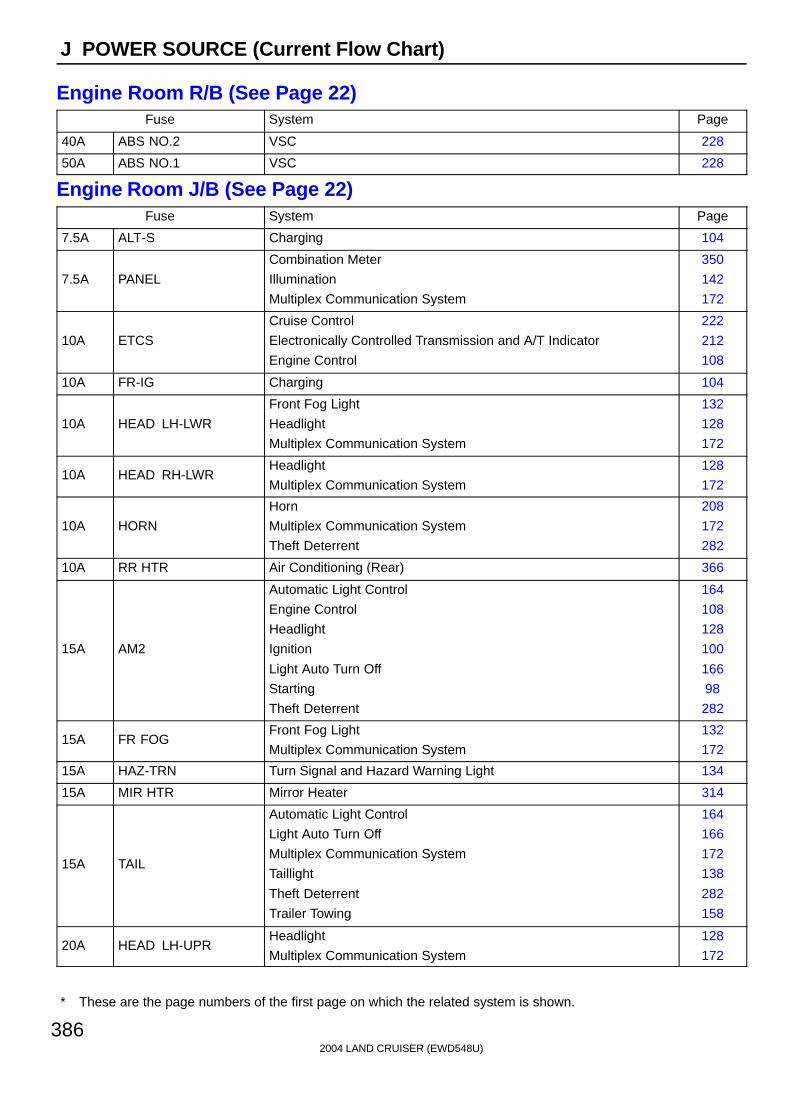
2004 LAND CRUISER (EWD548U)
386
J POWER SOURCE (Current Flow Chart)
Engine Room R/B (See Page 22)Fuse System Page
40A ABS NO.2 VSC 228
50A ABS NO.1 VSC 228
Engine Room J/B (See Page 22)Fuse System Page
7.5A ALT-S Charging 104
7.5A PANEL
Combination Meter
Illumination
Multiplex Communication System
350
142
172
10A ETCS
Cruise Control
Electronically Controlled Transmission and A/T Indicator
Engine Control
222
212
108
10A FR-IG Charging 104
10A HEAD LH-LWR
Front Fog Light
Headlight
Multiplex Communication System
132
128
172
10A HEAD RH-LWRHeadlight
Multiplex Communication System
128
172
10A HORN
Horn
Multiplex Communication System
Theft Deterrent
208
172
282
10A RR HTR Air Conditioning (Rear) 366
15A AM2
Automatic Light Control
Engine Control
Headlight
Ignition
Light Auto Turn Off
Starting
Theft Deterrent
164
108
128
100
166
98
282
15A FR FOGFront Fog Light
Multiplex Communication System
132
172
15A HAZ-TRN Turn Signal and Hazard Warning Light 134
15A MIR HTR Mirror Heater 314
15A TAIL
Automatic Light Control
Light Auto Turn Off
Multiplex Communication System
Taillight
Theft Deterrent
Trailer Towing
164
166
172
138
282
158
20A HEAD LH-UPRHeadlight
Multiplex Communication System
128
172
∗ These are the page numbers of the first page on which the related system is shown.

2004 LAND CRUISER (EWD548U)
387
J
Fuse System Page
20A HEAD RH-UPRHeadlight
Multiplex Communication System
128
172
25A EFI OR ECD NO.1
Cruise Control
Electronically Controlled Transmission and A/T Indicator
Engine Control
222
212
108
30A AMPRadio and Player (w/ Navigation System)
Radio and Player (w/o Navigation System)
324
330
30A STARTEREngine Control
Starting
108
98
30A TOWING Trailer Towing 158
30A TOWING BRK Trailer Towing 158
30A TOWING TAIL Trailer Towing 158
Cowl Side J/B LH (See Page 28)Fuse System Page
7.5A ACC
Auto Antenna
Automatic Light Control
Combination Meter
Door Lock Control
Engine Control
Headlight
Interior Light
Key Reminder
Light Auto Turn Off
Multi-Display (w/o Navigation System)
Multiplex Communication System
Navigation System and TOYOTA Parking Assist (Rear View Monitor)
Power Window
Radio and Player (w/ Navigation System)
Radio and Player (w/o Navigation System)
Remote Control Mirror
Theft Deterrent
Wireless Door Lock Control
322
164
350
260
108
128
148
316
166
348
172
336
250
324
330
302
282
270
7.5A AM1
Air Conditioning (Rear)
Engine Control
Mirror Heater
Rear Window Defogger
Shift Lock
366
108
314
312
244
7.5A IDLE UPMultiplex Communication System
Rear Window Defogger
172
312
7.5A OBD-2 Engine Control 108
∗ These are the page numbers of the first page on which the related system is shown.

2004 LAND CRUISER (EWD548U)
388
J POWER SOURCE (Current Flow Chart)
Fuse System Page
10A ECU-B1Multi-Display (w/o Navigation System)
Navigation System and TOYOTA Parking Assist (Rear View Monitor)
348
336
10A ECU-IG1
Automatic Glare-Resistant EC Mirror with Compass
Automatic Light Control
Door Lock Control
Headlight
Interior Light
Key Reminder
Light Auto Turn Off
Moon Roof
Multi-Display (w/o Navigation System)
Multiplex Communication System
Navigation System and TOYOTA Parking Assist (Rear View Monitor)
Power Window
Shift Lock
Theft Deterrent
VSC
Wireless Door Lock Control
304
164
260
128
148
316
166
256
348
172
336
250
244
282
228
270
10A EFI OR ECD NO.2 Engine Control 108
10A GAUGE1
Air Conditioning (Front)
Center Differential Lock
Combination Meter
Cruise Control
Electronically Controlled Transmission and A/T Indicator
Engine Control
Illumination
Key Reminder
Multiplex Communication System
Navigation System and TOYOTA Parking Assist (Rear View Monitor)
Power Rear Quarter Window
Seat Belt Warning
356
246
350
222
212
108
142
316
172
336
306
320
15A A/C
Air Conditioning (Front)
Air Conditioning (Rear)
Seat Belt Warning
356
366
320
15A CIG Cigarette Lighter 204
15A PWR OUTLET Power Outlet 206
15A RR WIPER Rear Wiper and Washer 200
15A STOP
Cruise Control
Electronically Controlled Transmission and A/T Indicator
Engine Control
Multiplex Communication System
222
212
108
172
∗ These are the page numbers of the first page on which the related system is shown.
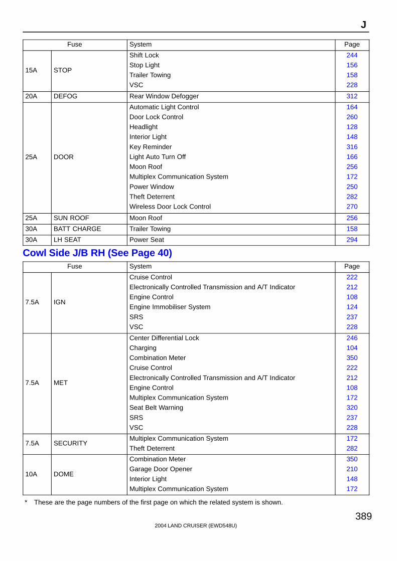
2004 LAND CRUISER (EWD548U)
389
J
Fuse System Page
15A STOP
Shift Lock
Stop Light
Trailer Towing
VSC
244
156
158
228
20A DEFOG Rear Window Defogger 312
25A DOOR
Automatic Light Control
Door Lock Control
Headlight
Interior Light
Key Reminder
Light Auto Turn Off
Moon Roof
Multiplex Communication System
Power Window
Theft Deterrent
Wireless Door Lock Control
164
260
128
148
316
166
256
172
250
282
270
25A SUN ROOF Moon Roof 256
30A BATT CHARGE Trailer Towing 158
30A LH SEAT Power Seat 294
Cowl Side J/B RH (See Page 40)Fuse System Page
7.5A IGN
Cruise Control
Electronically Controlled Transmission and A/T Indicator
Engine Control
Engine Immobiliser System
SRS
VSC
222
212
108
124
237
228
7.5A MET
Center Differential Lock
Charging
Combination Meter
Cruise Control
Electronically Controlled Transmission and A/T Indicator
Engine Control
Multiplex Communication System
Seat Belt Warning
SRS
VSC
246
104
350
222
212
108
172
320
237
228
7.5A SECURITYMultiplex Communication System
Theft Deterrent
172
282
10A DOME
Combination Meter
Garage Door Opener
Interior Light
Multiplex Communication System
350
210
148
172
∗ These are the page numbers of the first page on which the related system is shown.
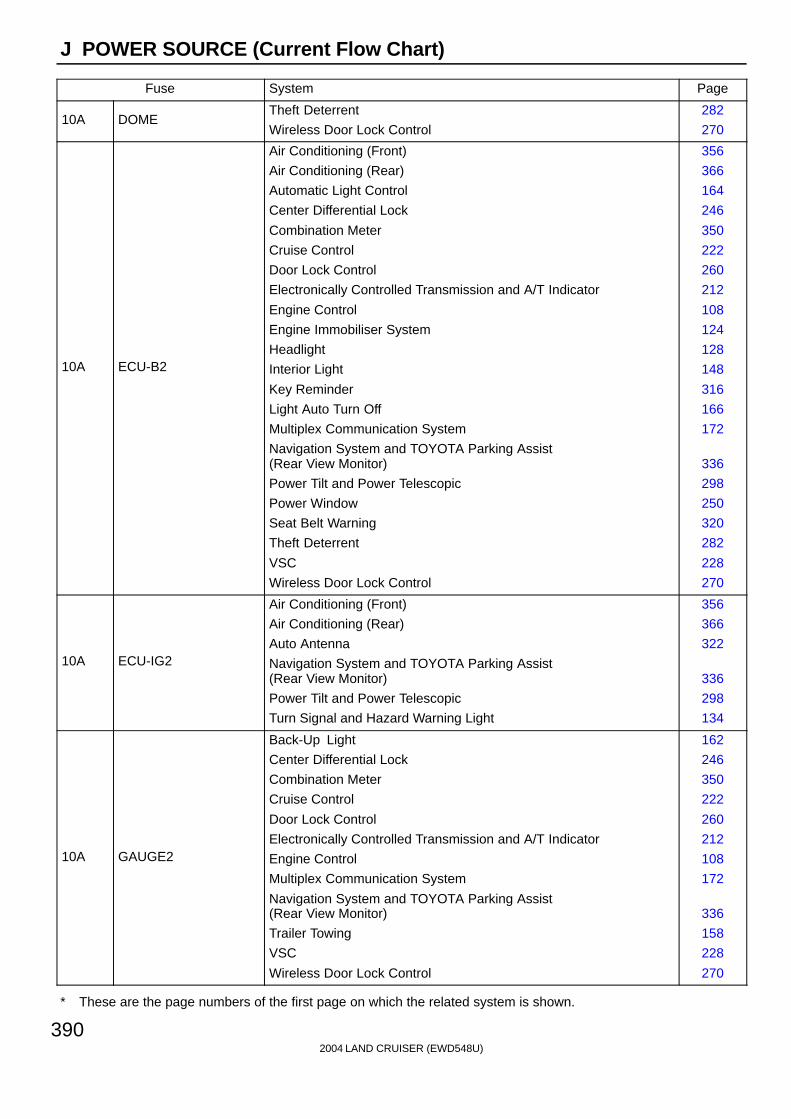
2004 LAND CRUISER (EWD548U)
390
J POWER SOURCE (Current Flow Chart)
Fuse System Page
10A DOMETheft Deterrent
Wireless Door Lock Control
282
270
10A ECU-B2
Air Conditioning (Front)
Air Conditioning (Rear)
Automatic Light Control
Center Differential Lock
Combination Meter
Cruise Control
Door Lock Control
Electronically Controlled Transmission and A/T Indicator
Engine Control
Engine Immobiliser System
Headlight
Interior Light
Key Reminder
Light Auto Turn Off
Multiplex Communication System
Navigation System and TOYOTA Parking Assist (Rear View Monitor)
Power Tilt and Power Telescopic
Power Window
Seat Belt Warning
Theft Deterrent
VSC
Wireless Door Lock Control
356
366
164
246
350
222
260
212
108
124
128
148
316
166
172
336
298
250
320
282
228
270
10A ECU-IG2
Air Conditioning (Front)
Air Conditioning (Rear)
Auto Antenna
Navigation System and TOYOTA Parking Assist (Rear View Monitor)
Power Tilt and Power Telescopic
Turn Signal and Hazard Warning Light
356
366
322
336
298
134
10A GAUGE2
Back-Up Light
Center Differential Lock
Combination Meter
Cruise Control
Door Lock Control
Electronically Controlled Transmission and A/T Indicator
Engine Control
Multiplex Communication System
Navigation System and TOYOTA Parking Assist (Rear View Monitor)
Trailer Towing
VSC
Wireless Door Lock Control
162
246
350
222
260
212
108
172
336
158
228
270
∗ These are the page numbers of the first page on which the related system is shown.

2004 LAND CRUISER (EWD548U)
391
J
Fuse System Page
10A RADIO
Auto Antenna
Navigation System and TOYOTA Parking Assist (Rear View Monitor)
Radio and Player (w/ Navigation System)
Radio and Player (w/o Navigation System)
322
336
324
330
15A SEAT HTR Seat Heater 308
15A WASHERFront Wiper and Washer
Rear Wiper and Washer
196
200
20A DIFF Center Differential Lock 246
20A P/W (FL)
Door Lock Control
Interior Light
Multiplex Communication System
Power Window
Theft Deterrent
Wireless Door Lock Control
260
148
172
250
282
270
20A P/W (FR)Multiplex Communication System
Power Window
172
250
20A P/W (RL)Multiplex Communication System
Power Window
172
250
20A P/W (RR)Multiplex Communication System
Power Window
172
250
20A TIL & TEL Power Tilt and Power Telescopic 298
25A WIPER Front Wiper and Washer 196
30A RH SEAT Power Seat 294
30A RR A/C Air Conditioning (Rear) 366
Fusible Link Block (F15, F16, F17, F18, F19 on See Page 68)Fuse System Page
50A HTR Air Conditioning (Front) 356
120A J/B NO.1
Automatic Light Control
Illumination
Light Auto Turn Off
Multiplex Communication System
Taillight
Theft Deterrent
164
142
166
172
138
282
120A J/B NO.2
Air Conditioning (Rear)
Engine Control
Mirror Heater
Rear Window Defogger
Shift Lock
366
108
314
312
244
120A J/B NO.3 Engine Control 108
120A MAIN
Ignition
Multiplex Communication System
Starting
100
172
98
∗ These are the page numbers of the first page on which the related system is shown.

2004 LAND CRUISER (EWD548U)
392
J POWER SOURCE (Current Flow Chart)
Fuse System Page
140A ALT
Air Conditioning (Front)
Air Conditioning (Rear)
Automatic Light Control
Charging
Engine Control
Illumination
Light Auto Turn Off
Mirror Heater
Multiplex Communication System
Rear Window Defogger
Shift Lock
Taillight
Theft Deterrent
356
366
164
104
108
142
166
314
172
312
244
138
282
∗ These are the page numbers of the first page on which the related system is shown.

2004 LAND CRUISER (EWD548U)
393
Memo

2004 LAND CRUISER (EWD548U)
20
F RELAY LOCATIONS
[Engine Compartment]
[Instrument Panel]

2004 LAND CRUISER (EWD548U)
21
F
[Body]

2004 LAND CRUISER (EWD548U)
22
F RELAY LOCATIONS
: Engine Room J/BEngine Compartment Left (See Page 20)
1 : Engine Room R/BEngine Compartment Left (See Page 20)
(Inner Circuit : See Page 26)

2004 LAND CRUISER (EWD548U)
23
F

2004 LAND CRUISER (EWD548U)
24
F RELAY LOCATIONS
: Engine Room J/B Engine Compartment Left (See Page 20)(Inner Circuit : See Page 26)
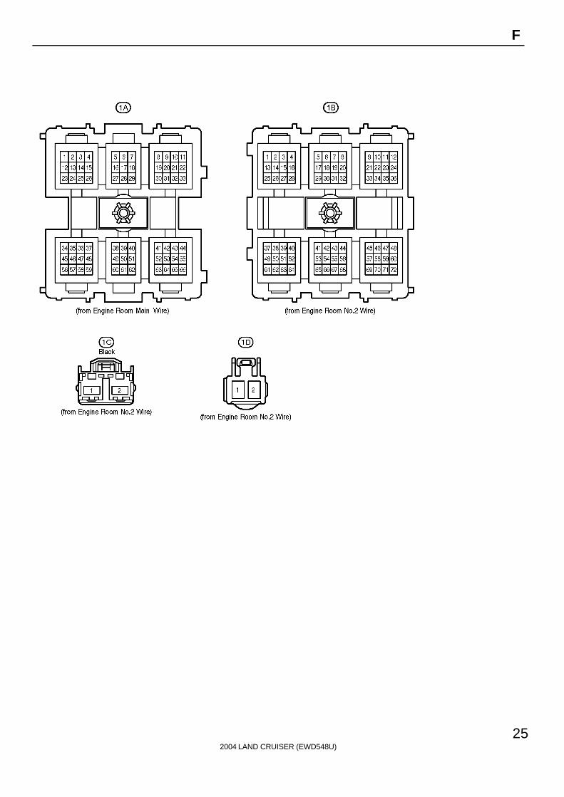
2004 LAND CRUISER (EWD548U)
25
F

2004 LAND CRUISER (EWD548U)
26
F RELAY LOCATIONS
[Engine Room J/B Inner Circuit]

2004 LAND CRUISER (EWD548U)
27
F

2004 LAND CRUISER (EWD548U)
28
F RELAY LOCATIONS
: Cowl Side J/B LH Left Kick Panel (See Page 20)(Inner Circuit : See Page 34)

2004 LAND CRUISER (EWD548U)
29
F
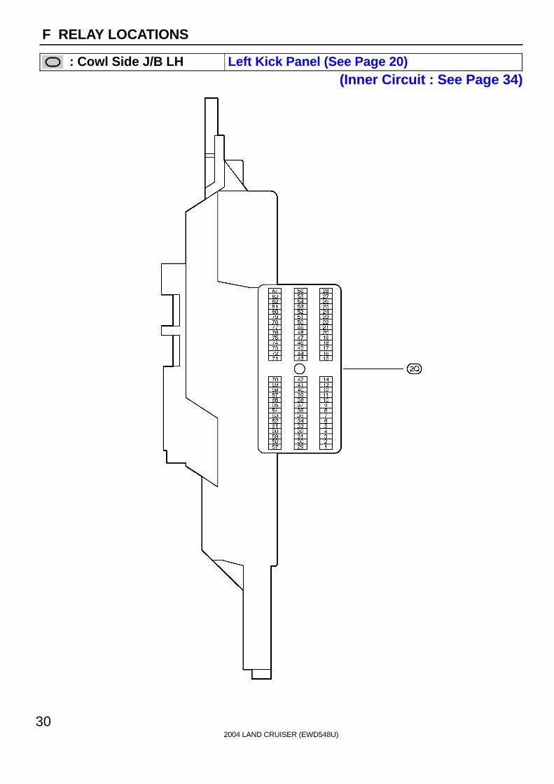
2004 LAND CRUISER (EWD548U)
30
F RELAY LOCATIONS
: Cowl Side J/B LH Left Kick Panel (See Page 20)(Inner Circuit : See Page 34)

2004 LAND CRUISER (EWD548U)
31
Memo

2004 LAND CRUISER (EWD548U)
32
F RELAY LOCATIONS
: Cowl Side J/B LH Left Kick Panel (See Page 20)(Inner Circuit : See Page 34)
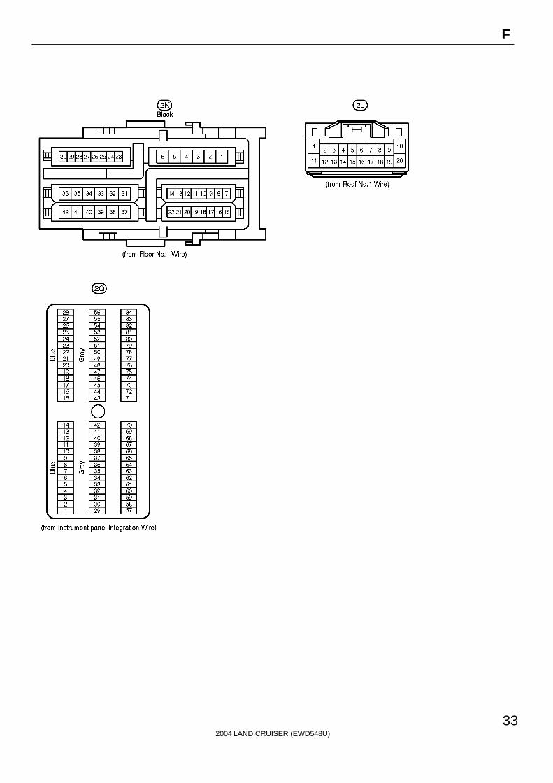
2004 LAND CRUISER (EWD548U)
33
F
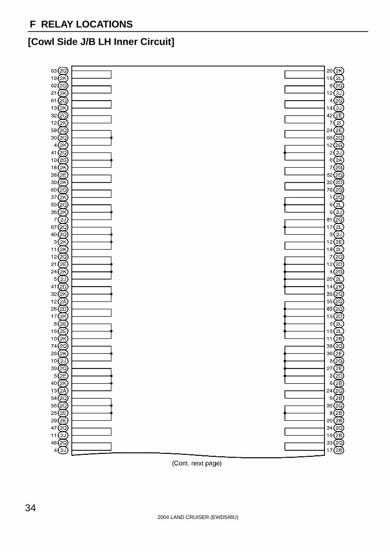
2004 LAND CRUISER (EWD548U)
34
F RELAY LOCATIONS
[Cowl Side J/B LH Inner Circuit]
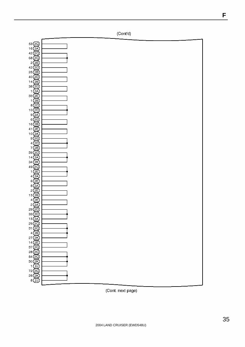
2004 LAND CRUISER (EWD548U)
35
F

2004 LAND CRUISER (EWD548U)
36
F RELAY LOCATIONS
[Cowl Side J/B LH Inner Circuit]

2004 LAND CRUISER (EWD548U)
37
F

2004 LAND CRUISER (EWD548U)
38
F RELAY LOCATIONS
[Cowl Side J/B LH Inner Circuit]

2004 LAND CRUISER (EWD548U)
39
Memo

2004 LAND CRUISER (EWD548U)
40
F RELAY LOCATIONS
: Cowl Side J/B RH Right Kick Panel (See Page 20)(Inner Circuit : See Page 46)

2004 LAND CRUISER (EWD548U)
41
F
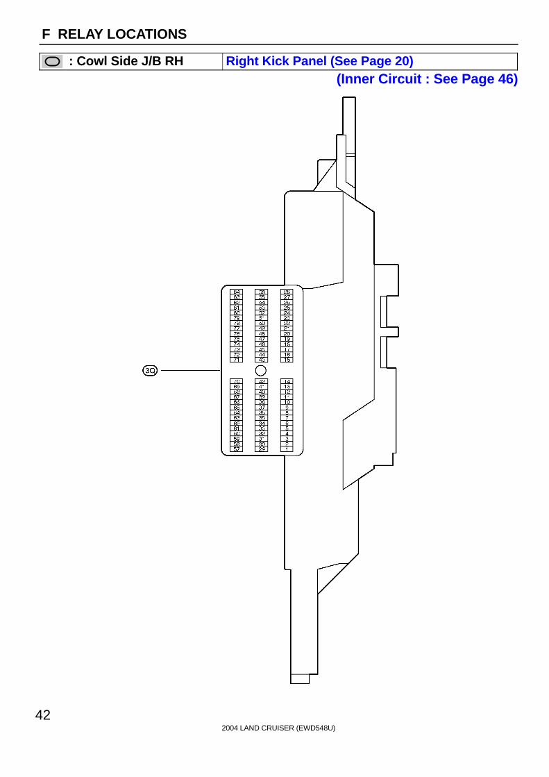
2004 LAND CRUISER (EWD548U)
42
F RELAY LOCATIONS
: Cowl Side J/B RH Right Kick Panel (See Page 20)(Inner Circuit : See Page 46)
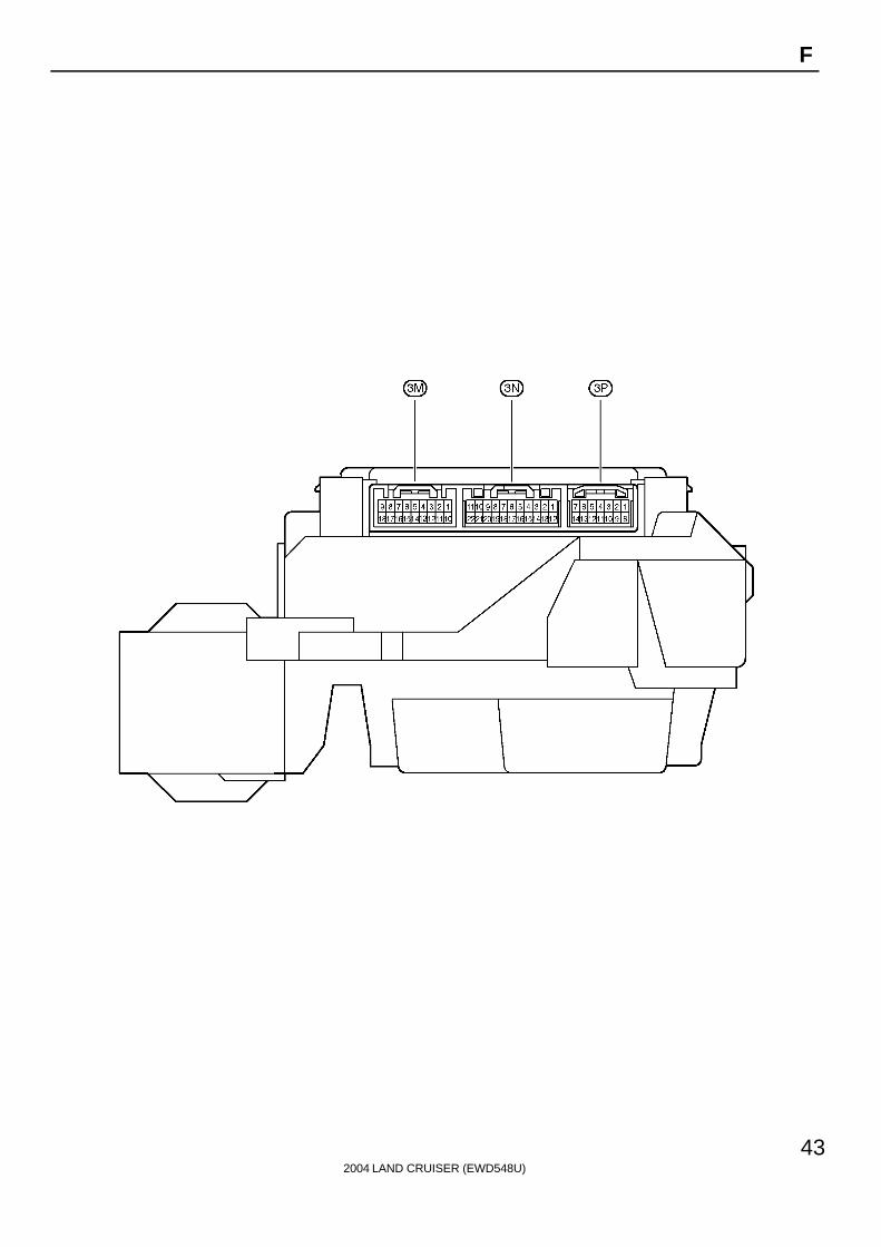
2004 LAND CRUISER (EWD548U)
43
F
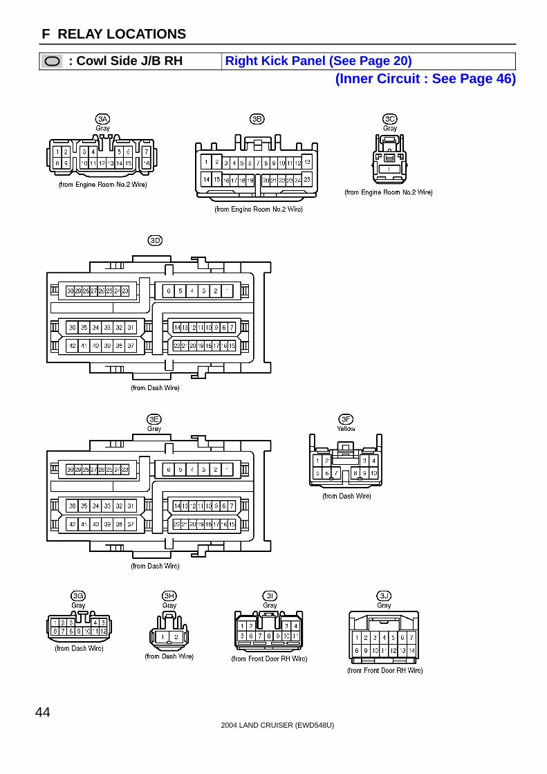
2004 LAND CRUISER (EWD548U)
44
F RELAY LOCATIONS
: Cowl Side J/B RH Right Kick Panel (See Page 20)(Inner Circuit : See Page 46)

2004 LAND CRUISER (EWD548U)
45
F

2004 LAND CRUISER (EWD548U)
46
F RELAY LOCATIONS
[Cowl Side J/B RH Inner Circuit]

2004 LAND CRUISER (EWD548U)
47
F

2004 LAND CRUISER (EWD548U)
48
F RELAY LOCATIONS
[Cowl Side J/B RH Inner Circuit]

2004 LAND CRUISER (EWD548U)
49
F

2004 LAND CRUISER (EWD548U)
50
F RELAY LOCATIONS
[Cowl Side J/B RH Inner Circuit]
2004 LAND CRUISER (EWD548U)
51
Memo
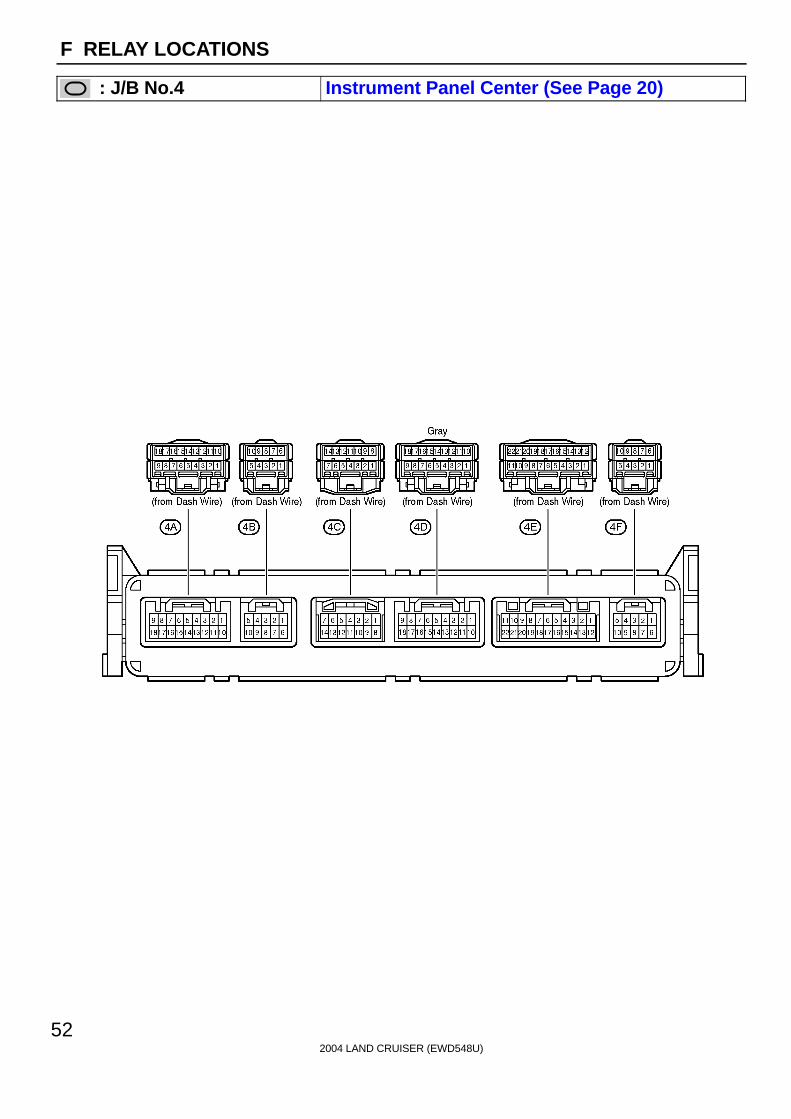
2004 LAND CRUISER (EWD548U)
52
F RELAY LOCATIONS
: J/B No.4 Instrument Panel Center (See Page 20)

2004 LAND CRUISER (EWD548U)
53
Memo
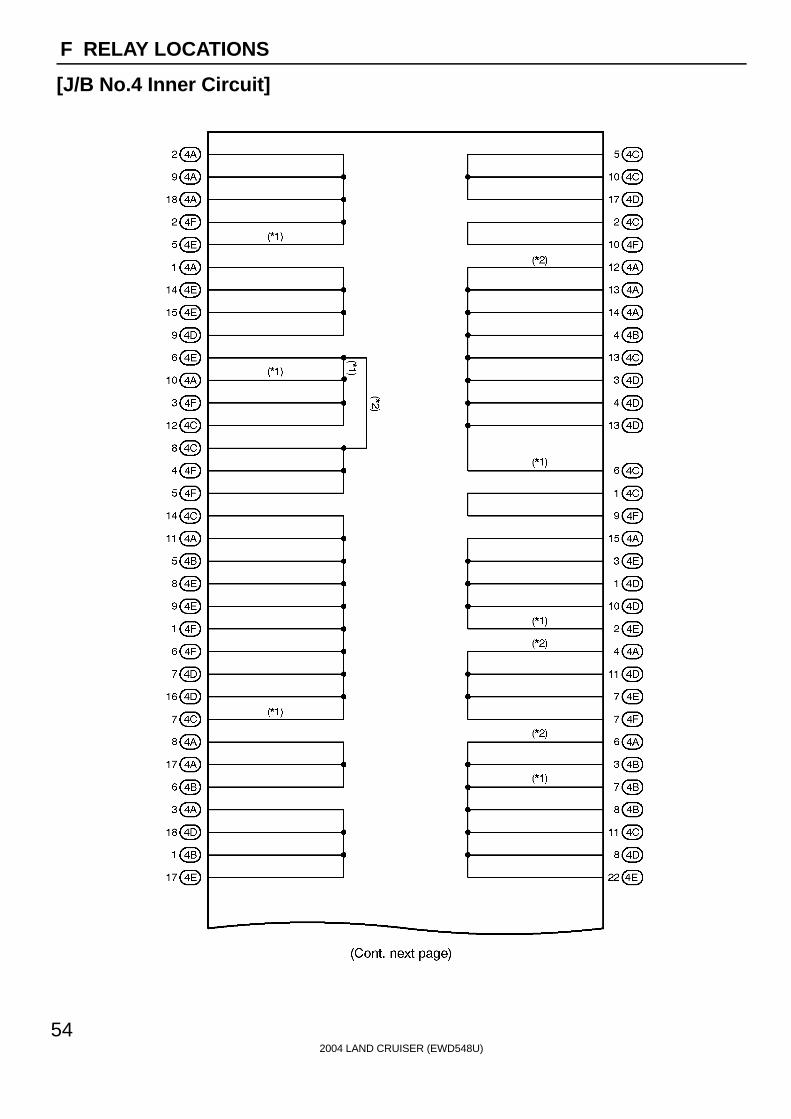
2004 LAND CRUISER (EWD548U)
54
F RELAY LOCATIONS
[J/B No.4 Inner Circuit]
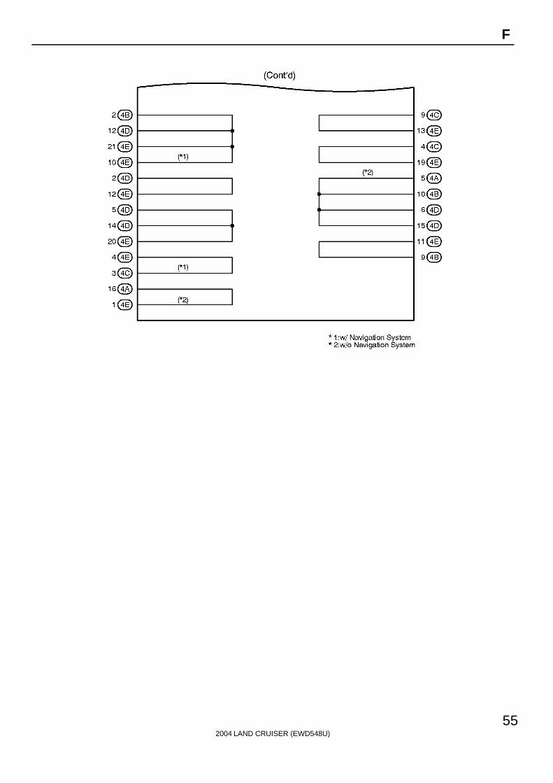
2004 LAND CRUISER (EWD548U)
55
F

2004 LAND CRUISER (EWD548U)
56
F RELAY LOCATIONS
: J/B No.5 Behind the Combination Meter (See Page 20)

2004 LAND CRUISER (EWD548U)
57
Memo

2004 LAND CRUISER (EWD548U)
58
F RELAY LOCATIONS
[J/B No.5 Inner Circuit]

2004 LAND CRUISER (EWD548U)
59
F

2004 LAND CRUISER (EWD548U)
60
F RELAY LOCATIONS
: J/B No.6 Behind the Glove Box (See Page 20)

2004 LAND CRUISER (EWD548U)
61
Memo
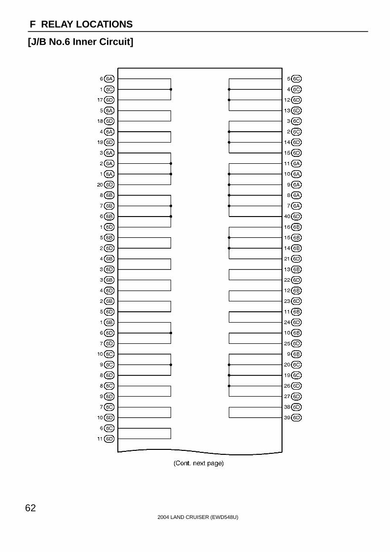
2004 LAND CRUISER (EWD548U)
62
F RELAY LOCATIONS
[J/B No.6 Inner Circuit]

2004 LAND CRUISER (EWD548U)
63
F

2004 LAND CRUISER (EWD548U)
64
F RELAY LOCATIONS
: J/B No.7 Behind the Glove Box (See Page 20)

2004 LAND CRUISER (EWD548U)
65
Memo

2004 LAND CRUISER (EWD548U)
66
F RELAY LOCATIONS
[J/B No.7 Inner Circuit]
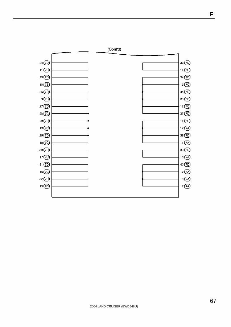
2004 LAND CRUISER (EWD548U)
67
F
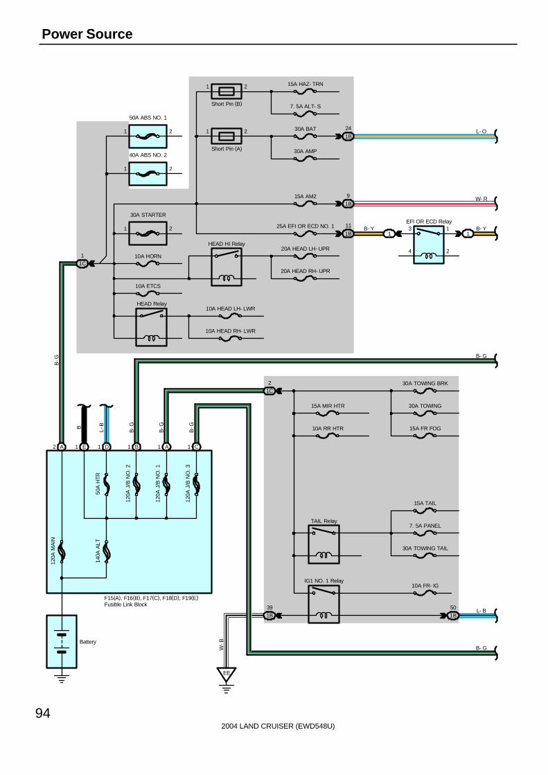
2004 LAND CRUISER (EWD548U)
94
Power Source
Battery
1C2
10A RR HTR
15A MIR HTR
1C1 10A HORN
30A STARTER
20A HEAD LH- UPR
20A HEAD RH- UPR
10A HEAD LH- LWR
10A HEAD RH- LWR
TAIL Relay
15A TAIL
IG1 NO. 1 Relay
7. 5A PANEL
10A FR- IG
1 2
HEAD HI Relay
HEAD Relay
10A ETCS
D1 B1 A1 C1A2
2
2
1
1
40A ABS NO. 2
50A ABS NO. 1
30A TOWING BRK
30A TOWING
15A FR FOG
15A HAZ- TRN
7. 5A ALT- S
30A BAT
30A AMP
Short Pin (B)
Short Pin (A)
1B
24
15A AM21B
9
1B50
25A EFI OR ECD NO. 11B
11EFI OR ECD Relay
2
1
4
311
F15(A), F16(B), F17(C), F18(D), F19(E)
B-G
B-G
B-GL-B
B-G
50A
HTR
120A
J/B
NO
. 1
120A
J/B
NO
. 2
120A
J/B
NO
. 3
140A
ALT
120A
MA
IN
L- B
B- G
B- Y B- Y
W- R
L- O
B- G
E1
B
1B39
EE
W-B
1
1
2
2
Fusible Link Block
30A TOWING TAIL
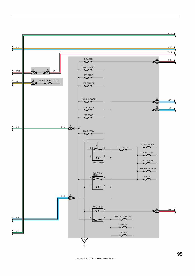
2004 LAND CRUISER (EWD548U)
95
2C
1
15A STOP
7. 5A AM1
5
1
3
2
1
5
2
3
2E
40
2E
37
IF
IG1 NO. 2Relay
15A A/C
ACC Relay
30A LH SEAT
10A ECU- B1
25A SUN ROOF
7. 5A OBD- 2
25A DOOR
20A DEFOG
30A BATT CHARGE
10A GAUGE1
10A ECU- IG1
15A RR WIPER7. 5A IDLE UP
15A PWR OUTLET
15A CIG
7. 5A ACC
2E
39
2E
41
2A
10
DEFOG Relay
2B3
2A
5 10A EFI OR ECD NO. 2
2Q
77
L- B
B- G
B- Y
W- R
L- O
B- G B- G
W- R
L- B
B- R
SB
L- B
W- R
L- O
B- G
B- R
54
2
3
1

2004 LAND CRUISER (EWD548U)
96
Power Source
I18
3C1
7. 5A SECURITY
20A TIL & TEL
30A RH SEAT
20A P/W (RR)
30A RR A/C
20A P/W (RL)
20A P/W (FR)
20A P/W (FL)
1
3
2
5 20A DIFF
10A RADIO
10A ECU- B2
10A DOME
3B
25
3E4 7. 5A IGN
7. 5A MET
2
7
3
4
6
8
AM2
AM1
ACC
IG1
IG2
ST2 B- W
L- B
B
IG1 NO. 3 Relay
B- G
10A ECU- IG2
15A WASHER
25A WIPER
10A GAUGE2
15A SEAT HTR
A A
J 4
ACC CUT Relay
1
3
2
4
6B4
6D3
3Q
50
II
3Q
39
B- R
L- B
SB
B- R
W- R
L- O
B- G
W- R
B- R
B- R
B
SB
IX14IX13
5 6B
6D2
B-R
B- R
3Q52SB
SB
SB
Ignition SW
JunctionConnector
6 7A
7A5
B

2004 LAND CRUISER (EWD548U)
97
I18 Ignition SW2-3 : Closed with ignition SW at ACC or ON position2-4 : Closed with ignition SW at ON or ST position7-6 : Closed with ignition SW at ON or ST position7-8 : Closed with ignition SW at ST position
: Parts Location
Code See Page Code See Page Code See Page
F15 A 68 F18 D 68 J4 71
F16 B 68 F19 E 68
F17 C 68 I18 70
: Relay Blocks
Code See Page Relay Blocks (Relay Block Location)
1 22 Engine Room R/B (Engine Compartment Left)
: Junction Block and Wire Harness Connector
Code See Page Junction Block and Wire Harness (Connector Location)
1B24 Engine Room No 2 Wire and Engine Room J/B (Engine Compartment Left)
1C24 Engine Room No.2 Wire and Engine Room J/B (Engine Compartment Left)
2A
2B 28 Engine Room No.2 Wire and Cowl Side J/B LH (Left Kick Panel)
2C
g ( )
2E 28 Dash Wire and Cowl Side J/B LH (Left Kick Panel)
2Q 30 Instrument Panel Integration Wire and Cowl Side J/B LH (Left Kick Panel)
3B40 Engine Room No 2 Wire and Cowl Side J/B RH (Right Kick Panel)
3C40 Engine Room No.2 Wire and Cowl Side J/B RH (Right Kick Panel)
3E 40 Dash Wire and Cowl Side J/B RH (Right Kick Panel)
3Q 42 Instrument Panel Integration Wire and Cowl Side J/B RH (Right Kick Panel)
6B 60 Dash Wire and J/B No.6 (Behind the Grove Box)
6D 60 Engine Wire and J/B No.6 (Behind the Grove Box)
7A 64 Dash Wire and J/B No.7 (Behind the Glove Box)
: Connector Joining Wire Harness and Wire Harness
Code See Page Joining Wire Harness and Wire Harness (Connector Location)
IX1 82 Instrument Panel Integration Wire and Engine Wire (Behind the Glove Box)
: Ground Points
Code See Page Ground Points Location
EE 76 Front Left Side of Fender Apron
IF 78 Set Bolt of Cowl Side J/B LH
II 78 Set Bolt of Cowl Side J/B RH
Service Hints

2004 LAND CRUISER (EWD548U)
98
Starting
120A
MA
IN
1C1
B-G
15AAM2
1
30ASTARTER
2
1B9 1D2
W-R
2A10
2E41
7
8
AM2 IG2
ST2
1
3 2
5 1
1 1 1
M
A1
B1
1B43
1B39
EE
6D14
6C3
6D155D14
5C3
P
N
9
6
A
AB
-WB
-W
C12
A16
6B1
6D6
B9 A17
B- W
W- R
W-R
B-W
B-W B-R
B-R
B-R
B-W
B- R
W- B
B- R
W-B
B- R
B- Y
E 5(A), E 6(B), E 7(C)
P 1
J17
I18
S 1(A), S 2(B)
F15
A
Battery
STA
RT
ER
Rel
ay
STSW
NSW STAR STA
ED11
B-W
Engine Control Module
Ignition SW
Park/NeutralPosition SW
Starter
Junc
tion
Con
nect
or
Fusible LinkBlock
2
B-W
B-R
If19
If112

2004 LAND CRUISER (EWD548U)
99
I18 Ignition SW7-8 : Closed with ignition SW at ST position
P1 Park/Neutral Position SW6-9 : Closed with A/T shift lever in P or N position
S1 (A), S2 (B) StarterPoints closed with Park/Neutral position SW at P or N position and ignition SW at ST position
: Parts Location
Code See Page Code See Page Code See Page
E5 A 70 F15 68 P1 69
E6 B 70 I18 70 S1 A 69
E7 C 70 J17 71 S2 B 69
: Relay Blocks
Code See Page Relay Blocks (Relay Block Location)
1 22 Engine Room R/B (Engine Compartment Left)
: Junction Block and Wire Harness Connector
Code See Page Junction Block and Wire Harness (Connector Location)
1B
1C 24 Engine Room No.2 Wire and Engine Room J/B (Engine Compartment Left)
1D
g g ( g )
2A 28 Engine Room No.2 Wire and Cowl Side J/B LH (Left Kick Panel)
2E 28 Dash Wire and Cowl Side J/B LH (Left Kick Panel)
5C 56 Dash Wire and J/B No.5 (Behind the Combination Meter)
5D 56 Engine Room No.2 Wire and J/B No.5 (Behind the Combination Meter)
6B60 Dash Wire and J/B No 6 (Behind the Grove Box)
6C60 Dash Wire and J/B No.6 (Behind the Grove Box)
6D 60 Engine Wire and J/B No.6 (Behind the Grove Box)
: Connector Joining Wire Harness and Wire Harness
Code See Page Joining Wire Harness and Wire Harness (Connector Location)
ED1 76 Engine No.2 Wire and Engine Room No.2 Wire (Near the Engine Room J/B)
If1 84 Engine Wire and Engine Wire (Behind the Glove Box)
: Ground Points
Code See Page Ground Points Location
EE 76 Front Left Side of Fender Apron
Service Hints
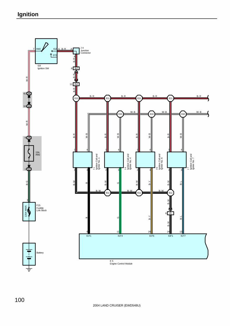
2004 LAND CRUISER (EWD548U)
100
Ignition
Battery
15AAM2
1C1
1B9
I18
7 6AM2 IG2
ST2
IN211
E11
I 1
1 4
2 3
IGT1
9
I 4
1 4
2 3 I 6
1 4
2 3 I 7
1 4
2 3
E11E11E11
IGT4
11
IGT6
26
IGT7
13
IGF1
24
B-WB
B-W G
B-W
B-WB-Y
B-L
B-W
B-L
B-YGB
E10 E10 E10
E11 E11 E11
W-B
W-B
B-R
W-B
B-R
W-B
B-R
B-R
B-R
W-R
W-R
B-G
B- WB- WB- W
B- R B- R B- R B- R
W- BW- BW- B
E 5
B-R
120A
MA
IN
2
F15
2E41
2A10
Ib28
A
A
B-R
B- R
If16
B-W
J 4
Engine Control Module
Igni
tion
Coi
l and
Igni
ter
No.
1
Igni
tion
Coi
l and
Igni
ter
No.
4
Igni
tion
Coi
l and
Igni
ter
No.
6
Igni
tion
Coi
l and
Igni
ter
No.
7
Ignition SW
JunctionConnector
FusibleLink Block

2004 LAND CRUISER (EWD548U)
101
I 2
1 4
3 2
E11
E11
E10
W-B
B-R
B-R
B-R
RR
8 23
IGT2 IGF2
I 3
1 4
3 2
E11
E11
E10
W-B
B-R
B-RL
L
25
L-B
IGT3
I 5
1 4
3 2
E11B- R
E11
E10
W-B
B-R
B-RY
Y
12
B- R
IGT5
B- R
I 81 4
3 2
IGT8
E11
E10
W-B
B-R
B-RL-B
10
ED
2
1
N 1
E 5
B- R
W- B
B- R B- R B- R B- R
W- B W- B W- B W- B
B-R
W-B
W-B
If17
B-R
EC
Engine Control Module
Igni
tion
Coi
l and
Igni
ter
No.
2
Igni
tion
Coi
l and
Igni
ter
No.
3
Igni
tion
Coi
l and
Igni
ter
No.
5
Igni
tion
Coi
l and
Igni
ter
No.
8
Noi
se F
ilter
( Ign
ition
)
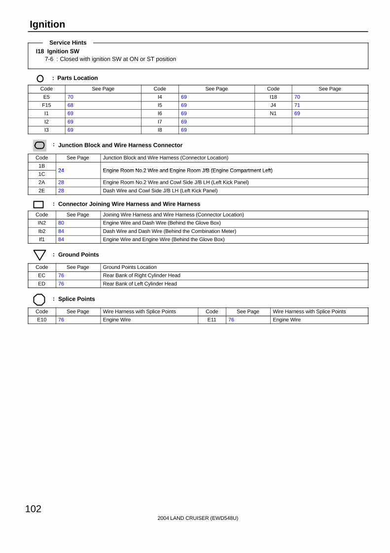
2004 LAND CRUISER (EWD548U)
102
Ignition
I18 Ignition SW7-6 : Closed with ignition SW at ON or ST position
: Parts Location
Code See Page Code See Page Code See Page
E5 70 I4 69 I18 70
F15 68 I5 69 J4 71
I1 69 I6 69 N1 69
I2 69 I7 69
I3 69 I8 69
: Junction Block and Wire Harness Connector
Code See Page Junction Block and Wire Harness (Connector Location)
1B24 Engine Room No 2 Wire and Engine Room J/B (Engine Compartment Left)
1C24 Engine Room No.2 Wire and Engine Room J/B (Engine Compartment Left)
2A 28 Engine Room No.2 Wire and Cowl Side J/B LH (Left Kick Panel)
2E 28 Dash Wire and Cowl Side J/B LH (Left Kick Panel)
: Connector Joining Wire Harness and Wire Harness
Code See Page Joining Wire Harness and Wire Harness (Connector Location)
IN2 80 Engine Wire and Dash Wire (Behind the Glove Box)
Ib2 84 Dash Wire and Dash Wire (Behind the Combination Meter)
If1 84 Engine Wire and Engine Wire (Behind the Glove Box)
: Ground Points
Code See Page Ground Points Location
EC 76 Rear Bank of Right Cylinder Head
ED 76 Rear Bank of Left Cylinder Head
: Splice Points
Code See Page Wire Harness with Splice Points Code See Page Wire Harness with Splice Points
E10 76 Engine Wire E11 76 Engine Wire
Service Hints

2004 LAND CRUISER (EWD548U)
103
Memo

2004 LAND CRUISER (EWD548U)
104
Charging
140A
ALT
7. 5AMET
3Q7
EC
IX18
A10 D19D20
D1
2Q66 4F3
2E24 4C12
IU19
B
P-B
BS
B
SB
D18 D29 C21
6C12
6D35
B-O
2B6
2E27
B
1A40
1B38
B
2G8
B
14
Cha
rge
L
EE12
B- O
From Power Source System (See Page 94)
C12(A), C15(D)B 7
E 7(C), E 8(D)
F19
SB
BR
SB
B
B- O
Battery
MPX1 MPX2 RL
B-O
B
Combination Meter
Engine ControlModule
Body ECU
FusibleLink Block
1
4A10
4E6
4C3
4E4
19 39
4 11
B ( *1)
P-B ( *1)
B ( *1)
P-B ( *1)
MPD1 MPD2
MPX+ MPX-
GatewayECU
G 4
A/C Control AssemblyA45
* 1 : w/ Navigation System
B-O
If18

2004 LAND CRUISER (EWD548U)
105
IG S BL
A2 A1 B1A4
10AFR- IG
From Power Source System (See Page 94)
1A60
7. 5AALT- S
1A39
EE11 EE13
B- O
G 1(A), G 2(B)
B-O B
B-W
W-L
B
B-W
W-L
Generator
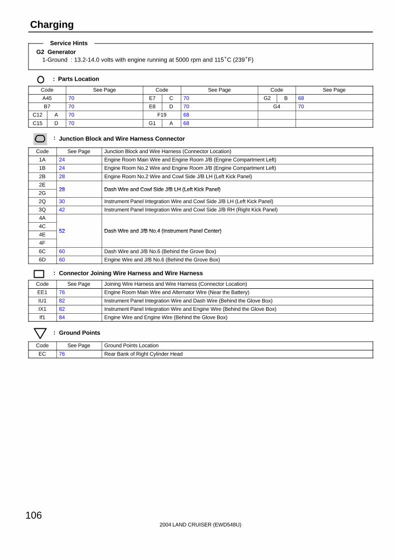
2004 LAND CRUISER (EWD548U)
106
Charging
G2 Generator1-Ground : 13.2-14.0 volts with engine running at 5000 rpm and 115°C (239°F)
: Parts Location
Code See Page Code See Page Code See Page
A45 70 E7 C 70 G2 B 68
B7 70 E8 D 70 G4 70
C12 A 70 F19 68
C15 D 70 G1 A 68
: Junction Block and Wire Harness Connector
Code See Page Junction Block and Wire Harness (Connector Location)
1A 24 Engine Room Main Wire and Engine Room J/B (Engine Compartment Left)
1B 24 Engine Room No.2 Wire and Engine Room J/B (Engine Compartment Left)
2B 28 Engine Room No.2 Wire and Cowl Side J/B LH (Left Kick Panel)
2E28 Dash Wire and Cowl Side J/B LH (Left Kick Panel)
2G28 Dash Wire and Cowl Side J/B LH (Left Kick Panel)
2Q 30 Instrument Panel Integration Wire and Cowl Side J/B LH (Left Kick Panel)
3Q 42 Instrument Panel Integration Wire and Cowl Side J/B RH (Right Kick Panel)
4A
4C52 Dash Wire and J/B No 4 (Instrument Panel Center)
4E52 Dash Wire and J/B No.4 (Instrument Panel Center)
4F
6C 60 Dash Wire and J/B No.6 (Behind the Grove Box)
6D 60 Engine Wire and J/B No.6 (Behind the Grove Box)
: Connector Joining Wire Harness and Wire Harness
Code See Page Joining Wire Harness and Wire Harness (Connector Location)
EE1 76 Engine Room Main Wire and Alternator Wire (Near the Battery)
IU1 82 Instrument Panel Integration Wire and Dash Wire (Behind the Glove Box)
IX1 82 Instrument Panel Integration Wire and Engine Wire (Behind the Glove Box)
If1 84 Engine Wire and Engine Wire (Behind the Glove Box)
: Ground Points
Code See Page Ground Points Location
EC 76 Rear Bank of Right Cylinder Head
Service Hints

2004 LAND CRUISER (EWD548U)
107
Memo
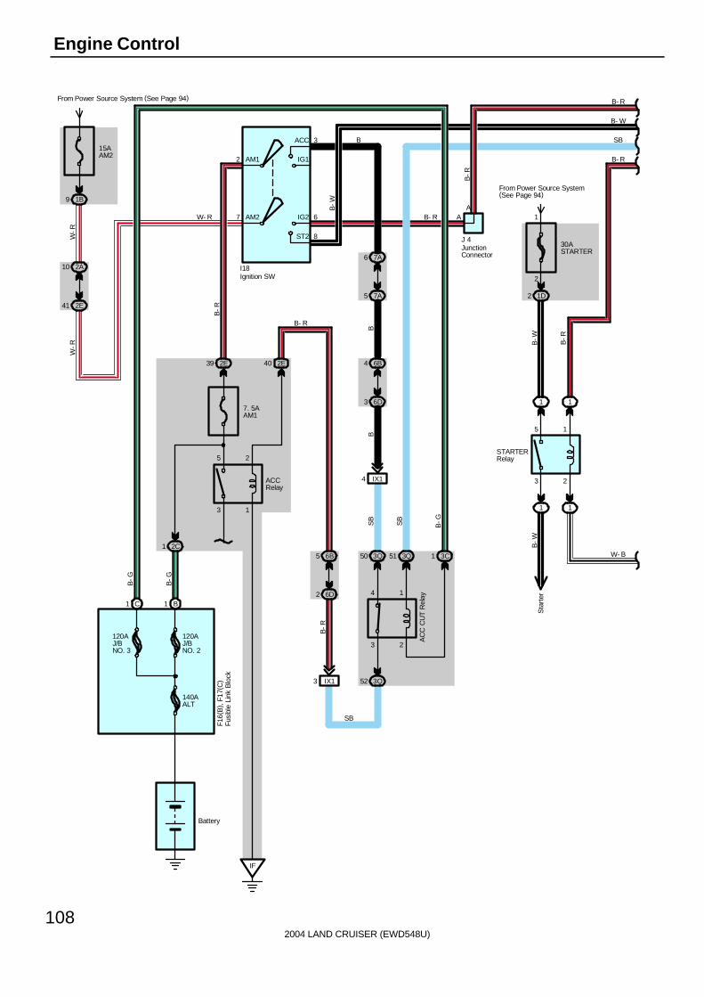
2004 LAND CRUISER (EWD548U)
108
Engine Control
15AAM2
From Power Source System (See Page 94)
1B9
2E41
2A10
2
7
3
6
8
AM2
AM1
ACC
IG1
IG2
ST2
B1C1
2E39
7. 5AAM1
3 1
5 2
2C1
IF
2E40
6B5
6D2
IX13 3Q52
4 1
3 2
3Q50 3Q51 3C1
6B4
6D3
IX14
AA
3 2
5 1
1 1
1 1
J 4
I18
ACCRelay
AC
C C
UT
Rel
ay
Battery
140AALT
120AJ/BNO. 3
120AJ/BNO. 2
W-R
W-R
B-R
W- RF1
6(B
) , F1
7(C
)
B-R
SB
30ASTARTER
From Power Source System(See Page 94)
1D2
STARTERRelay
B- RB
-W
B- R
B
B-G
B-G
SB
SB
B-G
B
B-R
1
2
B-W B-R
W- B
B- R
B- W
SB
B- R
Sta
rter
Ignition SW
JunctionConnector
Fusi
ble
Link
Blo
ck
B-W
B
7A6
7A5
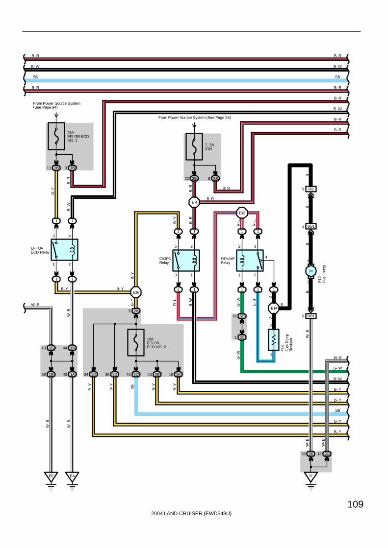
2004 LAND CRUISER (EWD548U)
109
1B43 1B44
1B39 1A43
EE EA
1 2
3 4
1 1
1 1
EFI ORECD Relay
From Power Source System(See Page 94)
1B11
B-Y
1B3
3 1
5 2
1 1
1 1
C/OPNRelay
10AEFI ORECD NO. 2
2A5
2Q45 2B10 2K162D362D34
7. 5AIGN
From Power Source System (See Page 94)
3B22
1 5
2 3
1 1
1 1
F/PUMPRelay
1
4
3E8
W- B
W-B
B-Y
B-Y
B- Y
5D16
5C1
1
2
IA29
BB12
5
4
BB18
IF
2K33 2D18
25AEFI OR ECDNO. 1
F14
F12
G-W L-
B
BB
G-W
R-L
B-W
R-L
R-LB
-Y
W-B
W-B
W-B
W-B
B-Y
B-Y SB
B-Y
W- B
G- W
B- W
B- Y
B- Y
SB
B- Y
B- Y
BW
-BB
BB
B- R
B- W
SB
B- R
B- R
B- W
SB
B- R
B- R
B- W
B- R
B-R
B-W
B- Y
B- R
B
B-Y
B- R
B-R
B-R
B- R
E13
E 4
E14
E16
Fuel
Pum
p
Fuel
Pum
pR
esis
tor
M
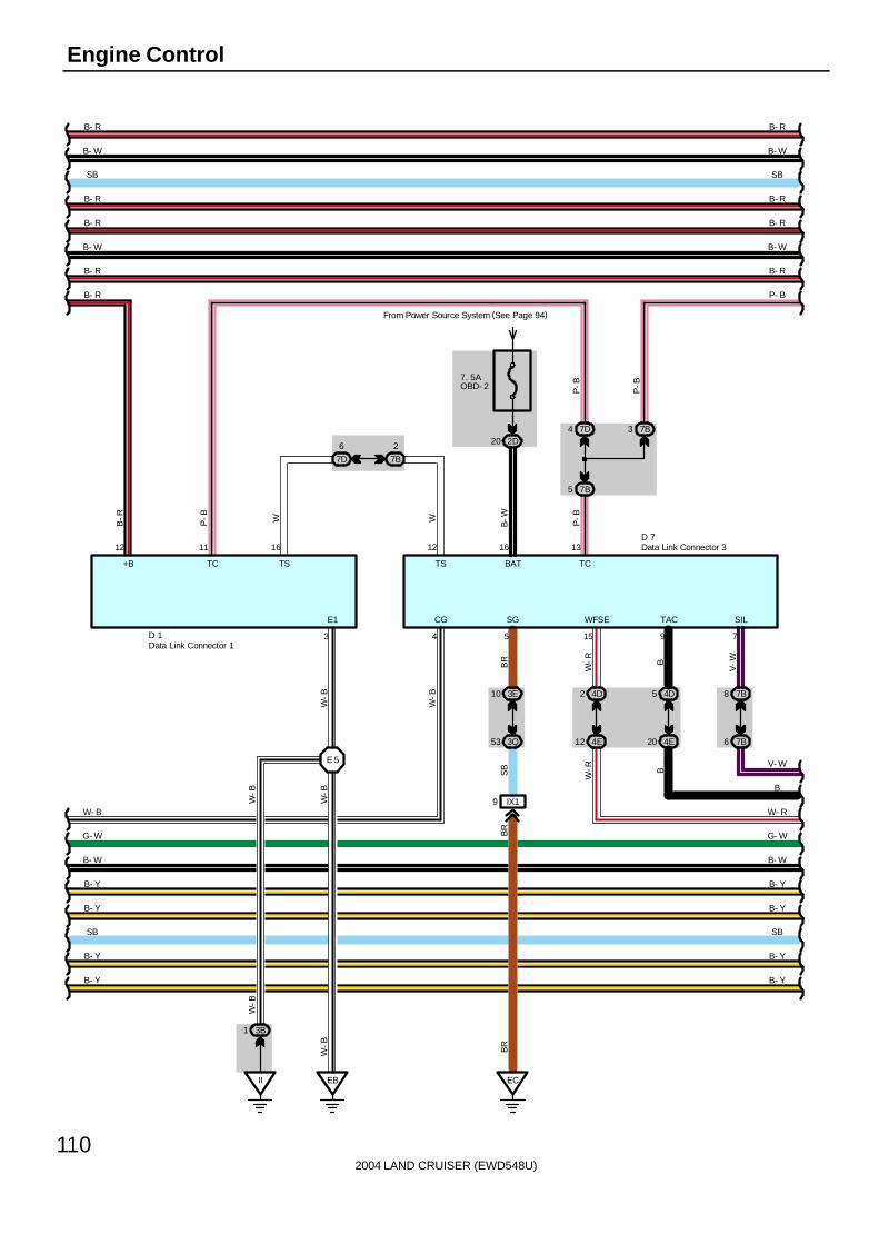
2004 LAND CRUISER (EWD548U)
110
Engine Control
7B
2
7D
6
7B5
7D4 7B3
7. 5AOBD- 2
From Power Source System (See Page 94)
2D20
3B1
II EB
3E10
3Q53
IX19
EC
4D2
4E12
4D5
4E20
7B8
7B6
W- B
G- W
B- W
B- Y
B- Y
SB
B- Y
B- Y
B- R
B- W
SB
B- R
B- R
B- W
B- R
12 11 16
3
+B TC TS
E1
W-B
W-B
W-B
W-B
W-B
W-B BR
D 1
12 16 13
4 5 15 9 7
W W B-W P-B
P-B
B-R
BR
W-R B
V-W
SB
W-R B
V- W
BR
TS BAT TC
CG SG WFSE TAC SIL
D 7
P-B
P-B
B- R
B- W
SB
B- R
B- R
B- W
P- B
B
W- R
G- W
B- W
B- Y
B- Y
SB
B- Y
B- Y
B- R B- R
E 5
Data Link Connector 1
Data Link Connector 3

2004 LAND CRUISER (EWD548U)
111
20 E
P-B
P-B
21 4E
12 4D 5D15
5C2
IG11
Id31Id15
2 IG1
10AETCS
From Power Source System (See Page 94)
1B2
IX17
4D9
4E14
P- B
B- R
B- W
B- R
B- R
SB
Y-B
Y-B
Y-B
R-G
Y-B
B-R
B-R
B-R
B-W
B-R
B-W
E
SB
V10
9 E8
B- R
E3 D6 A15
B- W
B- R
SB
B- W
B- R
4E17
4D18
E18
V-W
V- W
B
W- R
G- W
B- W
B- Y
B- Y
SB
B- Y
B- Y
E5 E19
6D10 5C4
6C7 5C13
A33 E10 E4
1
2
BD31
ID413
BD321
E1 E2
1
2
10 5D 6D9
5C7 6C8
A27
B- Y
B- Y
B
W-R
G-W
B-W L
B-Y
B-Y
L-R
L- R
L- R
B- Y
B-Y
B-Y
L
L
IX2
1
V 9
E 5(A), E 6(B), E 7(C), E 8(D), E 9(E)
IGSW
SIL
MRELTC BATT +BM ACCR
TACH WFSE FPR FC TBP +B +B2 CCV
E13
B-R
Engine Control Module
VS
V (
Can
iste
rC
lose
d V
alve
)
VS
V (
Pre
ssur
eS
witc
hing
Val
ve)
L-R
G-W
If113 If114
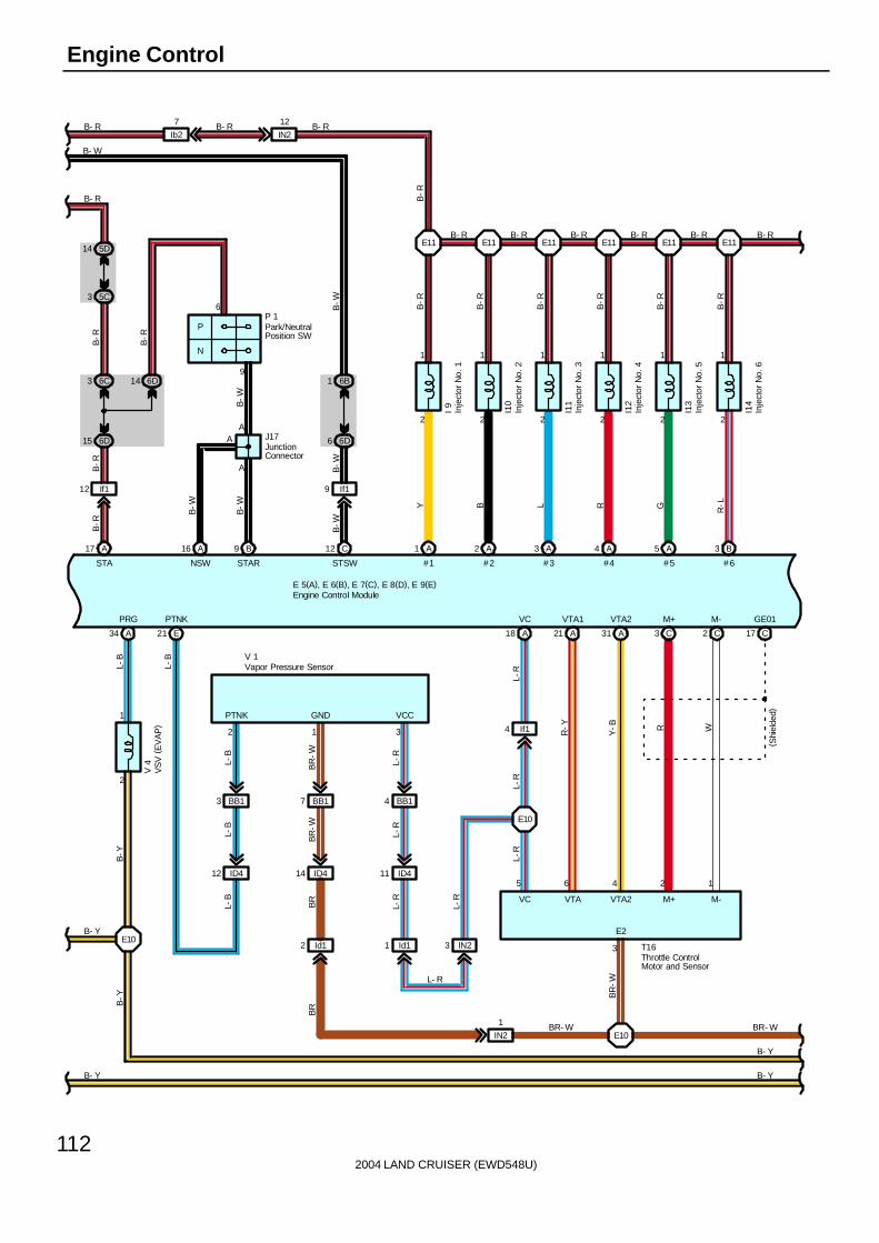
2004 LAND CRUISER (EWD548U)
112
Engine Control
E 5(A), E 6(B), E 7(C), E 8(D), E 9(E)
2
1
YB
-R
#1
A1
I 9
2
1
BB
-R
A2
I10
2
1
LB
-RA3
I11
2
1
RB
-R
A4
I12
2
1
GB
-R
A5
I13
2
1
R-L
B-R
B3
I14
IN2
12
Ib2
7
B9
A
A
P
N
14 6D
15 6D
3 6C
A17
B-W
B-W
B-R
5D14
5C36
96B1
6D6
C12
B-W
B-W
B-R
B-R
B-W
B-R
P 1
A
A
J17
B- R B- R B- R B- R B- R B- R
#3#2 #4 #5 #6STSWSTARNSWSTA
E21
3 BB1
ID412
BB17
ID414
Id12
BB14
ID411
Id11 IN23
If14
A18
L-R
A21 A31
L-R
C3 C2
L-R
C17
5
R-Y
Y-B R W
6 4 2 1
T16
B- Y
V 1
2 1 3
L-B
BR
-W
L-R
L-B
BR
-W
L-R
L-B
BR
L-R
L-R
L- R
BR- W
BR
PTNK GND VCC
VC VTA VTA2 M+ M-
2
1
A34
B- Y
B-Y
L-B
L-B
B-Y
V 4
B- Y
B- Y
PRG PTNK VC VTA1 VTA2 M+ M- GE01
( Shi
elde
d)
3
E2
BR
-W
E10
E10
E10
E11E11E11E11E11E11
B- R
B- W
B- R B- R B- R
IN2
1 BR- W
16
Engine Control Module
Inje
ctor
No.
1
Inje
ctor
No.
2
Inje
ctor
No.
3
Inje
ctor
No.
4
Inje
ctor
No.
5
Inje
ctor
No.
6
Park/NeutralPosition SW
Vapor Pressure Sensor
VS
V (
EV
AP
)
Throttle ControlMotor and Sensor
JunctionConnector
B-R
B-W
If19If112

2004 LAND CRUISER (EWD548U)
113
2
1
WB
-R
C6
I15
2
1
B-W
B-R
C5
I16
B- R
E 5(A), E 6(B), E 7(C), E 8(D), E 9(E)
6D35
6C12
2E27
2B6
1A40
1B38
C21
EE12
4
B-O
B-OB
B-O
L
G 1
A9
IGT1
B
A8
IGT2
R
A25
IGT3
L
A11
IGT4
G
A12
IGT5
YA26
IGT6B
-Y
A13
IGT7
B-L
A10
IGT8
L-B
A24
IGF1
B-W
A23
IGF2
B-R
Ignition Coil and Igniters
1
2
A19
G-B
BR
-W
IN28
IW36
L-Y
A30
L-Y
L-Y
5
IN22
IW35
G-W
A29
G-W
G-W
4
IN210
IW38
Y-B
A20
Y-B
Y-B
2
7 IW3 IN27
1
BR
BR
BR
-W
If13
A28
HT
B33 B22 B4B23
1 3 3 1
E 2
M 1
VG E2G THA E2
BR
-WB
R-W
OX
+B E1
OX
H 7
H 5
HT
+B E1
(Shielded)
(Shielded)
BR- W
B- Y
BR- W
B- Y
BR- W
B- Y
BR- WBR- WBR- W
B- Y
B- Y
WY B R
B-Y
BR
-W
BR
-W
B-Y
2 4 2 4
( Shi
elde
d)
( Shi
elde
d)
THW VG E2G THA E2 HT2A OX2A OX1A HT1A
#7 #8 RL
3
+B
B-Y
E11
E10 E10
E10E10
E10E10E10
Eng
ine
Coo
lant
Tem
p.
Sen
sor
Engine Control Module
Generator
Hea
ted
Oxy
gen
Sen
sor
( Ban
k 1
Sen
sor
1)
Hea
ted
Oxy
gen
Sen
sor
(B
ank
2 S
enso
r 1)
Inje
ctor
No.
7
Inje
ctor
No.
8
Mass Air Flow Meter
BB
-O
If18

2004 LAND CRUISER (EWD548U)
114
Engine Control
(Shielded)
(Shielded)
BR- W
B- Y
ELS1
E12
5C10
5B1
G-W
G-W
15
B 7
D2 E13
MG
CLT
Rel
ay
HTR
Rel
ay
L
Y-R
ELS ACMG ELS2
C23
LCKI
A/C
Loc
k S
enso
r
31 2D
From Power Source System (See Page 94)
15ASTOP
G-R
S 5
2D35
2E26
3M4
3M5
D19G
-W
G-W
G-W
G-W
STP
EB3
1
EB3
5
B21B25
1 3
HT OX
E1 +B
R-B W
BR
-W
B-Y
4 2
HT2B OX2B
9 EB3 EB311
R-B
W
H 8
8 EB3 EB33
B29 B5
3 1
EC
C CC
C
BR BR
C D D E
EB1
9
BR
BRBR- W BR- W
4 2
BR
-W
B-Y
E E EE
J17
(Shielded)
(Shielded)
(Shielded)
( Shi
elde
d)
BB
OX
( Shi
elde
d)
HT
E1 +B
(Shi
elde
d)
( Shi
elde
d)
( Shi
elde
d)
( Shi
elde
d)
( Shi
elde
d)
E 5(A), E 6(B), E 7(C), E 8(D), E 9(E)
OX1B HT1B
(Shielded)
3F5
3D30
4C4
4E19
E14
BB
F/PS
23
B
GSW2
3P6
3M16
Y
26 D
IMO
3P5
3M15
W
27 D
IMI
Y W
LL
BR
C26
B- Y
L
D
1
2
Center AirbagSensor Assembly
Engine Control Module
Hea
ted
Oxy
gen
Sen
sor
( Ban
k 2
Sen
sor
2)
Sto
p Li
ght S
W
Junction Connector
Body ECU
E10
E 8
E 8
Hea
ted
Oxy
gen
Sen
sor
( Ban
k 1
Sen
sor
2)
H 6
T19Transponder Key Computer
7
EFII
6
EFIO
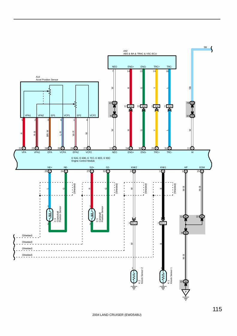
2004 LAND CRUISER (EWD548U)
115
2
1
C25 C24
C 3
L G
2
1
C27 C32
C 1
R G
(Shielded)
(Shielded)
(Shielded)
(Shielded)
1 1
B2 B1
EC13 EC12
K 2
K 1
W B
W B
IF
4C11 4E22
4D8
D1
2D22
E15
(Shi
elde
d)
( Shi
elde
d)
( Shi
elde
d)
( Shi
elde
d)
W-B
W-B
W-B
E 5(A), E 6(B), E 7(C), E 8(D), E 9(E)
NE+ NE- G2+ G2- KNK2 KNK1 HP EOM
5D12
5C5
IG412
RWW
ENG+
24 E17 E
R
7 14
ENG+
IG413
G
ENG-
30 E
G
22
ENG-
IG41
YTRC+
25 E
Y
24
TRC+
IG42
L
TRC-
31 E
L
16
TRC-NEO
NEO
2Q78
2D32
W
11 E
W
SB
SB
A42
E22
VPA
E23
VPA2
E28
EPA
E26
VCPA
E29
EPA2
E27
VCP2
R
R-B
BR
-W
L-R
W-R W
5 2 3 6 1 4
VPA1 VPA2 EP1 VCP1 EP2 VCP2
A14Accel Position Sensor
ABS & BA & TRAC & VSC ECU
Cam
shaf
tP
ositi
on S
enso
r
Cra
nksh
aft
Pos
ition
Sen
sor
Engine Control Module
Kno
ck S
enso
r 1
Kno
ck S
enso
r 2

2004 LAND CRUISER (EWD548U)
116
Engine Control
SB
2Q66
2E24
P-B
18 D
MPX1
4F3
4C12
B
29 D
MPX2
SB B
IU19
4E6 4E4
B
P-B
4 11
G 4
* 1 : w/ Navigation System
( *1)
( *1)
MPD1 MPD2
EC
A6 C7A7 C4 C1
W-B
W-B
W-B
W-B
W-B BR
BR
E 5(A), E 6(B), E 7(C), E 8(D), E 9(E)
E01 E02 E03 ME01 E1
W- B
D19 D20
SB
SB
SB
SB
D17
V
SPD
SB
C12(A), C13(B), C15(D)Combination Meter
Engine Control Module
Gateway ECU
E10 E10
2E28
2Q70
B
B
SB
J14JunctionConnector
SB
BR
BRE10
BRBR
3N12
3M7
G-B
G-B
D33
TW
3N18
3M17
P-B
P-B
D32
TEO
3N16
3M9
Y-G
Y-G
D14
ALED
3N14
3M8
L-B
L-B
D31
C
A45(A), A47(C)
4
A/CS
A11 C5 A7
ACLD THE THWO A/CS
A/C ControlAssembly
4A10 4C3
A39 A19
MPX- MPX+
P-B ( *1)B ( *1)
B(*1)
P- B(*1)

2004 LAND CRUISER (EWD548U)
117
Mal
func
tion
Indi
cato
r La
mp
10AECU- B2
From Power Source System (See Page 94)
3Q44
10AGAUGE1
2Q65 57 2Q
7. 5AACC
D12 D11 D13 A10
A
A
SB
SB
SB
SB
SB
D16 B11
SB
D15D1
IX16IX18
EB110EB19
32
SB
V 2
SB
R-G
BR
R-G
7. 5AMET
3Q7
SB
SB
J14
SB
Tach
omet
er
Spe
edom
eter
Vehicle Speed Sensor(Combination Meter)
JunctionConnector
C12(A), C13(B), C15(D)Combination Meter
EB111
1
R-L
10AGAUGE2
3E3
R-L
IN214
R-L
R-L
Ib26
R- LBR
BR
BR
BR

2004 LAND CRUISER (EWD548U)
118
Engine Control
The engine control system utilizes a microcomputer and maintains overall control of the engine, transmission etc. An outlineof the engine control is given here.
1. Input Signals(1) Engine coolant temp. signal circuit
The engine coolant temp. sensor detects the engine coolant temp. and has a built-in thermistor with a resistance whichvaries according to the engine coolant temp. The engine coolant temp. is input into TERMINAL THW of the enginecontrol module as a control signal.
(2) Intake air temp. signal circuitThe intake air temp. sensor is installed in the mass air flow meter and detects the intake air temp., which is input as acontrol signal to TERMINAL THA of the engine control module.
(3) Oxygen sensor signal circuitThe oxygen density in the exhaust emission is detected and is input as a control signal from the heated oxygen sensorsto TERMINALS OX1A, OX1B, OX2A, OX2B of the engine control module.
(4) RPM signal circuitThe camshaft position is detected by the camshaft position sensor and is input into TERMINAL G2+ of the enginecontrol module as a control signal. Also, the engine RPM is detected by the crankshaft position sensor and the signal isinput into TERMINAL NE+ of the engine control module.
(5) Throttle position sensor signal circuitThe throttle position sensor detects the throttle valve opening angle as a control signal, which is input into TERMINALSVTA1, VTA2 of the engine control module.
(6) Vehicle speed circuitThe vehicle speed sensor (Combination meter) detects the vehicle speed, and the signal is input into TERMINAL SPDof the engine control module via the combination meter.
(7) Battery signal circuitVoltage is constantly applied to TERMINAL BATT of the engine control module. When the ignition SW is turned on, thevoltage for engine control module start up power supply is applied through the EFI OR ECD relay, to TERMINALS +B,+B2 of the engine control module. The current from the IGN fuse flows to TERMINAL IGSW of the engine controlmodule, and voltage is constantly applied to TERMINAL +BM.
(8) Intake air volume signal circuitThe intake air volume is detected by the mass air flow meter, and is input as a control signal to TERMINAL VG of theengine control module.
(9) Stop light SW signal circuitThe stop light SW is used to detect whether the vehicle is braking or not, and the signal is input into TERMINAL STP ofthe engine control module as a control signal.
(10)Starter signal circuitTo confirm whether the engine is cranking, the voltage applied to the starter motor when the engine is cranking isdetected, and is input into TERMINAL STA of the engine control module as a control signal.
(11) Engine knock signal circuitEngine knocking is detected by the knock sensors, and is input into TERMINALS KNK1, KNK2 of the engine controlmodule as a control signal.
System Outline

2004 LAND CRUISER (EWD548U)
119
2. Control System∗ SFI system
The SFI system monitors the engine condition through the signals input from each sensors to the engine control module.The control signal is sent to the engine control module TERMINALS #1, #2, #3, #4, #5, #6, #7, #8 to operate the injector(Fuel injection). The SFI system controls the fuel injection by the engine control module in response to the drivingconditions.
∗ ESA systemThe ESA system monitors the engine condition through the signals input from each sensors to the engine control module.The best ignition timing is decided according to this data and the data memorized in the engine control module. Thecontrol signal is output to TERMINALS IGT1, IGT2, IGT3, IGT4, IGT5, IGT6, IGT7, IGT8, and these signals control theigniter to provide the best ignition timing.
∗ Heated oxygen sensor heater control systemThe heated oxygen sensor heater control system turns the heater on when the intake air volume is low (Temp. of exhaustemission is low), and warms up the heated oxygen sensors to improve their detection performance. The engine controlmodule evaluates the signals from each sensors, and outputs current to TERMINALS HT1A, HT1B, HT2A, HT2B tocontrol the heater.
∗ Fuel pump control systemThe engine control module supplies current to TERMINAL FPR, and controls the operation speed of the fuel pump by theF/PUMP relay.
∗ ACISThe ACIS includes a valve in the bulkhead separating the surge tank into two parts. This valve is opened and closed inaccordance with the driving conditions to control the intake manifold length in two stages, for increased engine output in allranges from low to high speeds.
∗ ETCS-iThe ETCS-i controls the engine output at its optimal level in accordance with the opening of the accelerator pedal, underall driving conditions.
3. Diagnosis SystemWhen there is a malfunction in the engine control module signal system, the malfunctioning system is recorded in thememory. The malfunctioning system can be found by reading the code displayed on the malfunction indicator lamp.
4. Fail-Safe SystemWhen a malfunction has occurred in any system, there is a possibility of causing engine trouble due to continued controlbased on that system. In that case, the fail-safe system either controls the system using the data (Standard values)recorded in the engine control module memory, or else stops the engine.
E2 Engine Coolant Temp. Sensor1-2 : Approx. 15.0 kΩ (-20°C, -4°F)
: Approx. 2.45 kΩ (20°C, 68°F): Approx. 0.32 kΩ (80°C, 176°F)
E5 (A), E7 (C), E8 (D), E9 (E) Engine Control ModuleBATT-E1 : Always 9.0-14.0 volts+BM-E1 : Always 9.0-14.0 volts
IGSW-E1 : 9.0-14.0 volts with ignition SW at ON or ST position+B, +B2-E1 : 9.0-14.0 volts with ignition SW at ON or ST position
VC-E2 : 4.5-5.5 volts with ignition SW onVTA2-E2 : 2.0-2.9 volts with ignition SW on and accelerator pedal released
: 4.6-5.1 volts with ignition SW on and accelerator pedal depressedVTA1-E2 : 0.4-1.0 volts with ignition SW on and accelerator pedal released
: 3.2-4.8 volts with ignition SW on and accelerator pedal depressedTHA-E2 : 0.5-3.4 volts with idling, intake air temp. 20°C (68°F)THW-E2 : 0.2-1.0 volts with idling, engine coolant temp. 80°C (176°F)
W-E1 : 9.0-14.0 volts with idling: Below 3.0 volts with ignition SW on
Service Hints

2004 LAND CRUISER (EWD548U)
120
Engine Control
: Parts Location
Code See Page Code See Page Code See Page
A14 70 E9 E 70 I16 69
A42 70 F12 72 I18 70
A45 A 70 F14 68 J4 71
A47 C 70 F16 B 68 J14 71
B7 70 F17 C 68 J17 71
C1 68 G1 68 K1 69
C3 68 G4 70 K2 69
C12 A 70 H5 69 M1 69
C13 B 70 H6 69 P1 69
C15 D 70 H7 69 S5 71
C26 70 H8 69 T16 69
D1 68 I9 69 T19 71
D7 70 I10 69 V1 73
E2 68 I11 69 V2 69
E5 A 70 I12 69 V4 69
E6 B 70 I13 69 V9 69
E7 C 70 I14 69 V10 73
E8 D 70 I15 69
: Relay Blocks
Code See Page Relay Blocks (Relay Block Location)
1 22 Engine Room R/B (Engine Compartment Left)

2004 LAND CRUISER (EWD548U)
121
: Junction Block and Wire Harness Connector
Code See Page Junction Block and Wire Harness (Connector Location)
1A 24 Engine Room Main Wire and Engine Room J/B (Engine Compartment Left)
1B24 Engine Room No 2 Wire and Engine Room J/B (Engine Compartment Left)
1D24 Engine Room No.2 Wire and Engine Room J/B (Engine Compartment Left)
2A
2B 28 Engine Room No.2 Wire and Cowl Side J/B LH (Left Kick Panel)
2C
g ( )
2D28 Dash Wire and Cowl Side J/B LH (Left Kick Panel)
2E28 Dash Wire and Cowl Side J/B LH (Left Kick Panel)
2K 28 Floor No.1 Wire and Cowl Side J/B LH (Left Kick Panel)
2Q 30 Instrument Panel Integration Wire and Cowl Side J/B LH (Left Kick Panel)
3B40 Engine Room No 2 Wire and Cowl Side J/B RH (Right Kick Panel)
3C40 Engine Room No.2 Wire and Cowl Side J/B RH (Right Kick Panel)
3D
3E 40
3FDash Wire and Cowl Side J/B RH (Right Kick Panel)
3MDash Wire and Cowl Side J/B RH (Right Kick Panel)
3N 43
3P
3Q 42 Instrument Panel Integration Wire and Cowl Side J/B RH (Right Kick Panel)
4A
4C
4D 52 Dash Wire and J/B No.4 (Instrument Panel Center)
4E
( )
4F
5B56 Dash Wire and J/B No 5 (Behind the Combination Meter)
5C56 Dash Wire and J/B No.5 (Behind the Combination Meter)
5D 56 Engine Room No.2 Wire and J/B No.5 (Behind the Combination Meter)
6B60 Dash Wire and J/B No 6 (Behind the Grove Box)
6C60 Dash Wire and J/B No.6 (Behind the Grove Box)
6D 60 Engine Wire and J/B No.6 (Behind the Grove Box)
7A64 Dash Wire and J/B No 7 (Behind the Grove Box)
7B64 Dash Wire and J/B No.7 (Behind the Grove Box)
7D 64 Engine Room No.2 Wire and J/B No.7 (Behind the Grove Box)
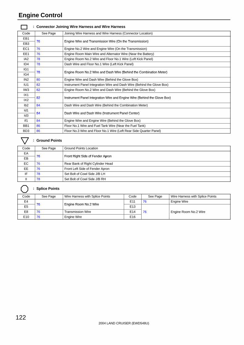
2004 LAND CRUISER (EWD548U)
122
Engine Control
: Connector Joining Wire Harness and Wire Harness
Code See Page Joining Wire Harness and Wire Harness (Connector Location)
EB176 Engine Wire and Transmission Wire (On the Transmission)
EB376 Engine Wire and Transmission Wire (On the Transmission)
EC1 76 Engine No.2 Wire and Engine Wire (On the Transmission)
EE1 76 Engine Room Main Wire and Alternator Wire (Near the Battery)
IA2 78 Engine Room No.2 Wire and Floor No.1 Wire (Left Kick Panel)
ID4 78 Dash Wire and Floor No.1 Wire (Left Kick Panel)
IG178 Engine Room No 2 Wire and Dash Wire (Behind the Combination Meter)
IG478 Engine Room No.2 Wire and Dash Wire (Behind the Combination Meter)
IN2 80 Engine Wire and Dash Wire (Behind the Glove Box)
IU1 82 Instrument Panel Integration Wire and Dash Wire (Behind the Glove Box)
IW3 82 Engine Room No.2 Wire and Dash Wire (Behind the Glove Box)
IX182 Instrument Panel Integration Wire and Engine Wire (Behind the Glove Box)
IX282 Instrument Panel Integration Wire and Engine Wire (Behind the Glove Box)
Ib2 84 Dash Wire and Dash Wire (Behind the Combination Meter)
Id184 Dash Wire and Dash Wire (Instrument Panel Center)
Id384 Dash Wire and Dash Wire (Instrument Panel Center)
If1 84 Engine Wire and Engine Wire (Behind the Glove Box)
BB1 86 Floor No.1 Wire and Fuel Tank Wire (Near the Fuel Tank)
BD3 86 Floor No.3 Wire and Floor No.1 Wire (Left Rear Side Quarter Panel)
: Ground Points
Code See Page Ground Points Location
EA76 Front Right Side of Fender Apron
EB76 Front Right Side of Fender Apron
EC 76 Rear Bank of Right Cylinder Head
EE 76 Front Left Side of Fender Apron
IF 78 Set Bolt of Cowl Side J/B LH
II 78 Set Bolt of Cowl Side J/B RH
: Splice Points
Code See Page Wire Harness with Splice Points Code See Page Wire Harness with Splice Points
E476 Engine Room No 2 Wire
E11 76 Engine Wire
E576 Engine Room No.2 Wire
E13
E8 76 Transmission Wire E14 76 Engine Room No.2 Wire
E10 76 Engine Wire E16
g

2004 LAND CRUISER (EWD548U)
123
Memo
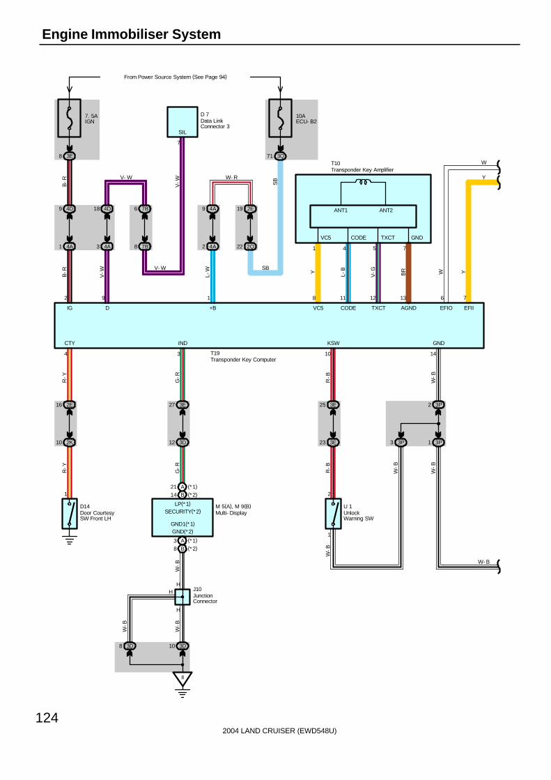
2004 LAND CRUISER (EWD548U)
124
Engine Immobiliser System
7. 5AIGN
3E8
B-R
4D9
4A1
B-R
2
4D18
4A3
V-W
9
7B6
7B8
4A9
4A2
L-W
1
2E19
2Q22
10AECU- B2
From Power Source System (See Page 94)
3Q71
4
2E16
2K10
R-Y
1
R-Y
10
3E25
3E23
R-B
2
R-B
1
3P3
14
3P2
3P1
W-B
3
3E27
3D12
G-R
G-R
A3 (*1)
B8 (*2)
H
H
II
3D103D8
W-B
A21 (*1)
B14 (*2)
W-B
W-B
H
ANT2ANT1
VC5 CODE TXCT GND
8 11 12 13
7
76
V-W SBV- W
V- W SB
W- R
D 7
T10
T19
1 4 5 7
Y L-B
V-G BR W Y
Y
W
W- B
W-B
W-B
W-B
SIL
IG D +B VC5 CODE TXCT AGND EFIO EFII
CTY IND KSW GND
D14 M 5(A), M 9(B) U 1
J10
GND(*2)GND1(*1)
LP(*1)SECURITY(*2)
Data LinkConnector 3
Door CourtesySW Front LH
Multi- Display
Transponder Key Amplifier
UnlockWarning SW
Transponder Key Computer
JunctionConnector
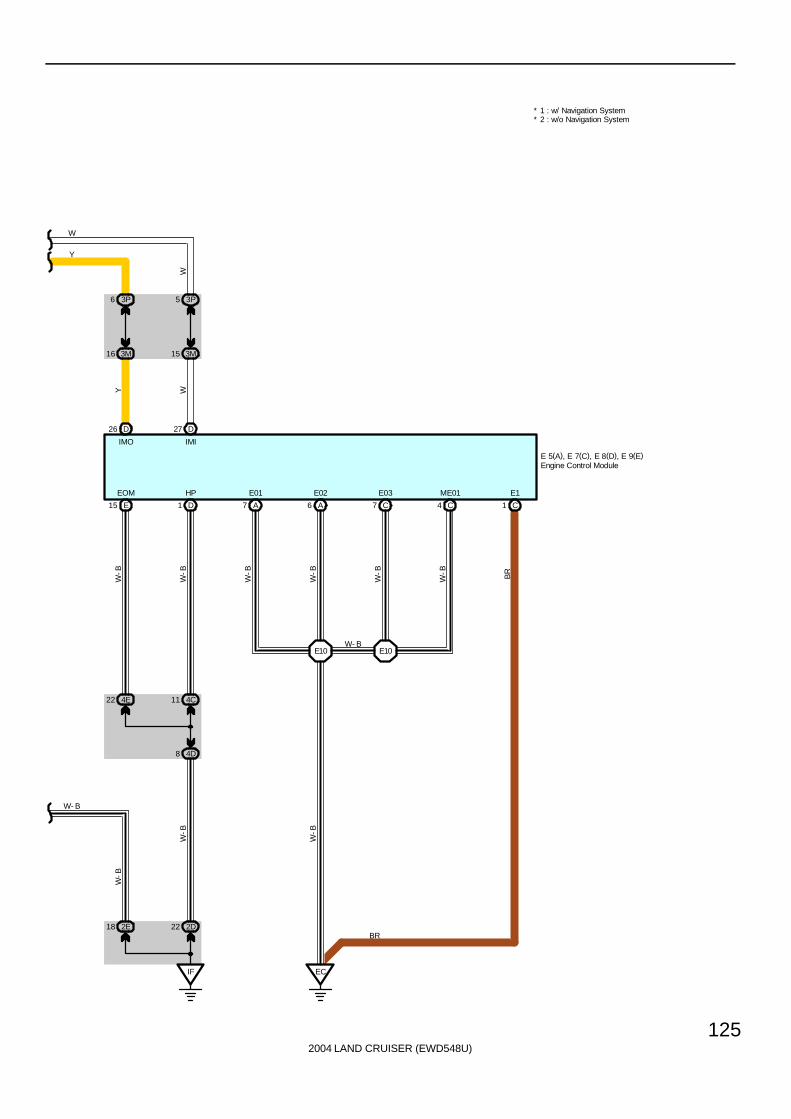
2004 LAND CRUISER (EWD548U)
125
A7 A6 C7 C4
E10 E10
EC
C1E15 D1
IF
2E18 2D22
4E22 4C11
4D8
D26 D27
3P6
3M16
3P5
3M15
W
Y
W
Y W
W-B
W-B
W-B BR
W-B
W-B
W-B
W-B
W-B
W-B
W- B
BR
W- B
E 5(A), E 7(C), E 8(D), E 9(E)
IMO IMI
EOM HP E01 E02 E03 ME01 E1
* 2 : w/o Navigation System* 1 : w/ Navigation System
Engine Control Module

2004 LAND CRUISER (EWD548U)
126
Engine Immobiliser System
T19 Transponder Key Computer1-Ground : Always approx. 12 volts2-Ground : Approx. 12 volts with ignition SW at ON or ST position
14-Ground : Always continuity
: Parts Location
Code See Page Code See Page Code See Page
D7 70 E8 D 70 M9 B 71
D14 72 E9 E 70 T10 71
E5 A 70 J10 71 T19 71
E7 C 70 M5 A 71 U1 71
: Junction Block and Wire Harness Connector
Code See Page Junction Block and Wire Harness (Connector Location)
2D28 Dash Wire and Cowl Side J/B LH (Left Kick Panel)
2E28 Dash Wire and Cowl Side J/B LH (Left Kick Panel)
2K 28 Floor No.1 Wire and Cowl Side J/B LH (Left Kick Panel)
2Q 30 Instrument Panel Integration Wire and Cowl Side J/B LH (Left Kick Panel)
3D40
3E40
Dash Wire and Cowl Side J/B RH (Right Kick Panel)3M
43
Dash Wire and Cowl Side J/B RH (Right Kick Panel)
3P43
3Q 42 Instrument Panel Integration Wire and Cowl Side J/B RH (Right Kick Panel)
4A
4C52 Dash Wire and J/B No 4 (Instrument Panel Center)
4D52 Dash Wire and J/B No.4 (Instrument Panel Center)
4E
7B 64 Dash Wire and J/B No.7 (Behind the Grove Box)
: Ground Points
Code See Page Ground Points Location
EC 76 Rear Bank of Right Cylinder Head
IF 78 Set Bolt of Cowl Side J/B LH
II 78 Set Bolt of Cowl Side J/B RH
: Splice Points
Code See Page Wire Harness with Splice Points Code See Page Wire Harness with Splice Points
E10 76 Engine Wire
Service Hints

2004 LAND CRUISER (EWD548U)
127
Memo

2004 LAND CRUISER (EWD548U)
128
Headlight
B 7(A), B 8(B), B 9(C)
Head
Tail
OFF
Ligh
t Con
trol
SW
Dim
mer
SW
Flash
High
Low
Auto
II54
II33
IU35
E
E
C
C
16
13 8
J 9
J 9
A
A
II
3E35
7
J 3
C16
C
W-B
R-Y
SB
SB
R-Y
R-Y
R-W
R-B
R-Y
W-B
W-B
C7C1
II52
II53
Bea
m
A7
SB
C18
C1
C2 B2
A7
DRL
2E11 2B5
C20
From Power Source System (See Page 94)
7. 5
A A
CC
10A
EC
U-I
G1
10A
EC
U-B
2
2Q22
3Q71
2K27
2Q31
1
BECU
SB
11 10 22
SIG ACC
R- Y
A5
IG16
IU44
R-Y
1A22
1B13
SB
SB
R-Y
R-Y
R-Y
2Q37
2E14
R-W
SB
R-W
P 8
R-Y
PKB
R-B
R-W
D
D
R-B
HUHFHEAD
HF2
R-W
R-W
R-W R-Y
17
HRLY
A
A
J13
R- W
R- Y
C12
( A) ,
C14
( C)
2G8
1B38
2B6
1A40
A14
L
BB
L
4
B-O
G 1
IF IG
4 16
GND1 GND2
Com
bina
tion
Met
er
Combination SW
Gen
erat
or
Par
king
Bra
ke S
W
Body ECU
JunctionConnector
Junc
tion
Con
nect
or
Junc
tion
Con
nect
or
Junc
tion
Con
nect
or
EE12
B-O
25A
DO
OR
12
BDR1
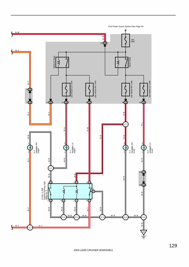
2004 LAND CRUISER (EWD548U)
129
R-Y
R-Y
W-B
W-B
R-W
W-B
R-B
R-L
W-B
1A30
1A24
2
1
2
1
2
1
9 2G
7 2B 10 1B 9 1A
10A
HE
AD
RH
-LW
R
20A
HE
AD
RH
-UP
R
1A8
10A
HE
AD
LH
-LW
R
E 1
26 1A
15AAM2
From Power Source System (See Page 94)
H 2
H 4
H 1
HE
AD
Rel
ay
HE
AD
HI
Rel
ay
20A
HE
AD
LH
-UP
R
1A12
R-G
E 2
EA
A5A1B4B2
B1 B3 A2
A3
2
1
R-Y
1B22
E 2E 2E 2E 2
E 1
E 1
W-B
R-B
R-B
W- BW- B
R-B
W-B
W-B
W-B
R-Y
W-B
W-B
W-B
R-Y
W-B
W- BW- B
R- YR- Y
R-Y
R-W
R- Y
R- W
D 2
( A) ,
D 3
( B)
H 3
Day
time
Run
ning
Lig
htR
elay
No.
3
Hea
dlig
ht L
H( H
igh)
Hea
dlig
ht L
H( L
ow)
Hea
dlig
ht R
H( H
igh)
Hea
dlig
ht R
H( L
ow)

2004 LAND CRUISER (EWD548U)
130
Headlight
Daytime Running Light OperationWhen the engine is started, a signal from the generator is input into TERMINAL (A) 14 of the body ECU. At this time, if theparking brake lever is pulled up (Parking brake SW ON), the body ECU is not activated, and the daytime running lightsystem does not operate.When the parking brake lever is released (Parking brake SW OFF), a signal is input into TERMINAL (B) 2 of the body ECU.This activates the body ECU and the headlight turns on.
C16 Combination SW13-16 : Closed with light control SW at HEAD position
8-16 : Closed with dimmer SW at FLASH position7-16 : Closed with dimmer SW at HIGH or FLASH position
: Parts Location
Code See Page Code See Page Code See Page
B7 A 70 D2 A 68 H4 69
B8 B 70 D3 B 68 J3 71
B9 C 70 G1 68 J9 71
C12 A 70 H1 69 J13 71
C14 C 70 H2 69 P8 73
C16 70 H3 69
: Junction Block and Wire Harness Connector
Code See Page Junction Block and Wire Harness (Connector Location)
1A 24 Engine Room Main Wire and Engine Room J/B (Engine Compartment Left)
1B 24 Engine Room No.2 Wire and Engine Room J/B (Engine Compartment Left)
2B 28 Engine Room No.2 Wire and Cowl Side J/B LH (Left Kick Panel)
2E28 Dash Wire and Cowl Side J/B LH (Left Kick Panel)
2G28 Dash Wire and Cowl Side J/B LH (Left Kick Panel)
2K 28 Floor No.1 Wire and Cowl Side J/B LH (Left Kick Panel)
2Q 30 Instrument Panel Integration Wire and Cowl Side J/B LH (Left Kick Panel)
3E 40 Dash Wire and Cowl Side J/B RH (Right Kick Panel)
3Q 42 Instrument Panel Integration Wire and Cowl Side J/B RH (Right Kick Panel)
: Connector Joining Wire Harness and Wire Harness
Code See Page Joining Wire Harness and Wire Harness (Connector Location)
EE1 76 Engine Room Main Wire and Alternator Wire (Near the Battery)
IG1 78 Engine Room No.2 Wire and Dash Wire (Behind the Combination Meter)
II380 Dash Wire and Column Wire (Near the Ignition SW)
II580 Dash Wire and Column Wire (Near the Ignition SW)
IU382 Instrument Panel Integration Wire and Dash Wire (Behind the Glove Box)
IU482 Instrument Panel Integration Wire and Dash Wire (Behind the Glove Box)
: Ground Points
Code See Page Ground Points Location
EA 76 Front Right Side of Fender Apron
IF78 Set Bolt of Cowl Side J/B LH
IG78 Set Bolt of Cowl Side J/B LH
II 78 Set Bolt of Cowl Side J/B RH
: Splice Points
Code See Page Wire Harness with Splice Points Code See Page Wire Harness with Splice Points
E1 76 Engine Room Main Wire E2 76 Engine Room Main Wire
System Outline
Service Hints

2004 LAND CRUISER (EWD548U)
131
Memo

2004 LAND CRUISER (EWD548U)
132
Front Fog Light
15AFR FOG
From Power Source System (See Page 94)
1A621A64
EA
R-B
R-B
W-B
1
2F
2
W-B
1
2
F 1
W-B
E15
10AHEADLH- LWR
61 1A
1A19
II33
A
A
II
3E35
J 3
R-L
W-B
W-B
1B5916 2A
53 2Q
R-L
FR FOGRelay
G- Y
SB
SB
G-Y
Fron
t Fo
g Li
ght L
H
Fron
t Fo
g Li
ght R
H
Junc
tion
Con
nect
or
C
C
JunctionConnector
J 6
Low
High
Flash
OFF
ON
Dim
mer
SW
Fog
Ligh
tS
W
11
1710 16
Combination SWC16
W-B
IH23

2004 LAND CRUISER (EWD548U)
133
C16 Combination SW11-Ground : Continuity with light control SW at HEAD position, dimmer SW at LOW position and fog light SW at ON position
: Parts Location
Code See Page Code See Page Code See Page
C16 70 F2 68 J6 71
F1 68 J3 71
: Junction Block and Wire Harness Connector
Code See Page Junction Block and Wire Harness (Connector Location)
1A 24 Engine Room Main Wire and Engine Room J/B (Engine Compartment Left)
1B 24 Engine Room No.2 Wire and Engine Room J/B (Engine Compartment Left)
2A 28 Engine Room No.2 Wire and Cowl Side J/B LH (Left Kick Panel)
2Q 30 Instrument Panel Integration Wire and Cowl Side J/B LH (Left Kick Panel)
3E 40 Dash Wire and Cowl Side J/B RH (Right Kick Panel)
: Connector Joining Wire Harness and Wire Harness
Code See Page Joining Wire Harness and Wire Harness (Connector Location)
IH2 80 Instrument Panel Integration Wire and Column Wire (Near the Ignition SW)
II3 80 Dash Wire and Column Wire (Near the Ignition SW)
: Ground Points
Code See Page Ground Points Location
EA 76 Front Right Side of Fender Apron
II 78 Set Bolt of Cowl Side J/B RH
: Splice Points
Code See Page Wire Harness with Splice Points Code See Page Wire Harness with Splice Points
E15 76 Engine Room Main Wire
Service Hints

2004 LAND CRUISER (EWD548U)
134
Turn Signal and Hazard Warning Light
EE
1B39 1A43
1A37
2
3
1A47
1B37
2A13
5 2E
BM
3
4
2K40
39 2Q
B11
Turn
15AHAZ- TRN
From Power Source System (See Page 94)
1B65
2B15
2E2
B- W
G- W
G- B
SB
G- Y
W-B
W-B
W-B
W-B
W-B
G-B SB
G- W
G-B
G-B
G-B
G-B
G-B
G-Y
G- B
F 3
R10
W- B
Fron
t Tu
rn S
igna
l Lig
ht L
H
Rea
r C
ombi
natio
nLi
ght
LH
BD29 BL51
9 3
Towing ConverterRelay
T15
3E
10AECU- IG2
32
B- W
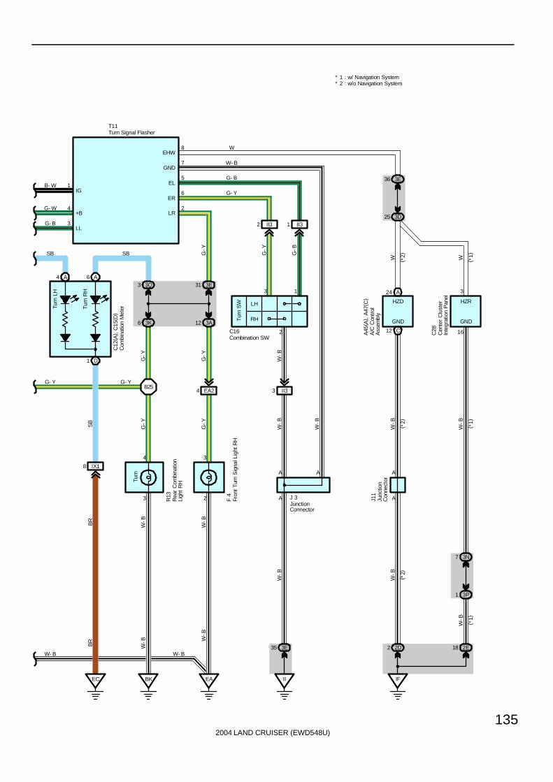
2004 LAND CRUISER (EWD548U)
135
Turn
LH
Tur
n R
H
A4 A6
D1
IX18
EC BK
3
4
3K6
3 3Q
B25
Turn
EA
2
3
3A12
31 3E
LH
RHTur
n S
W
II32 II31
A24
C12
EA24 II33
IF
2D2 2E18
3P1
3N7
3D25
3E36
SB
3
4 2
6
5
7
8
G- W
G- B
G- Y
W-B
W-B
BR
W-B W
-BW
-B
W-BBR
SB
G-Y
G-Y
W-B
W-B
W-B
W
W-B
G-Y
G-Y
G-Y
G-B
W
G-Y
SB
G- Y
G- Y
G- B
W- B
W
W-B
W-B
A
3
AA
A A
16
T11
C16 C28
J11
R13
F 4 J 3
C12
( A) ,
C15
( D)
W- B W- B
+B
LL
EHW
GND
EL
ER
LR
13
2
( *2)
( *1)
( *2)
( *2)
( *1)
( *1)
HZR
GND
* 2 : w/o Navigation System* 1 : w/ Navigation System
Com
bina
tion
Met
er
Combination SW
Fron
t Tu
rn S
igna
l Lig
ht R
H
Rea
r C
ombi
natio
nLi
ght
RH
Turn Signal Flasher
Junc
tion
Con
nect
or
JunctionConnector
Cen
ter
Clu
ster
Inte
grat
ion
Pan
el
HZD
GND
A45
( A) ,
A47
( C)
A/C
Con
trol
Ass
embl
y
II
3E35
1B- WIG
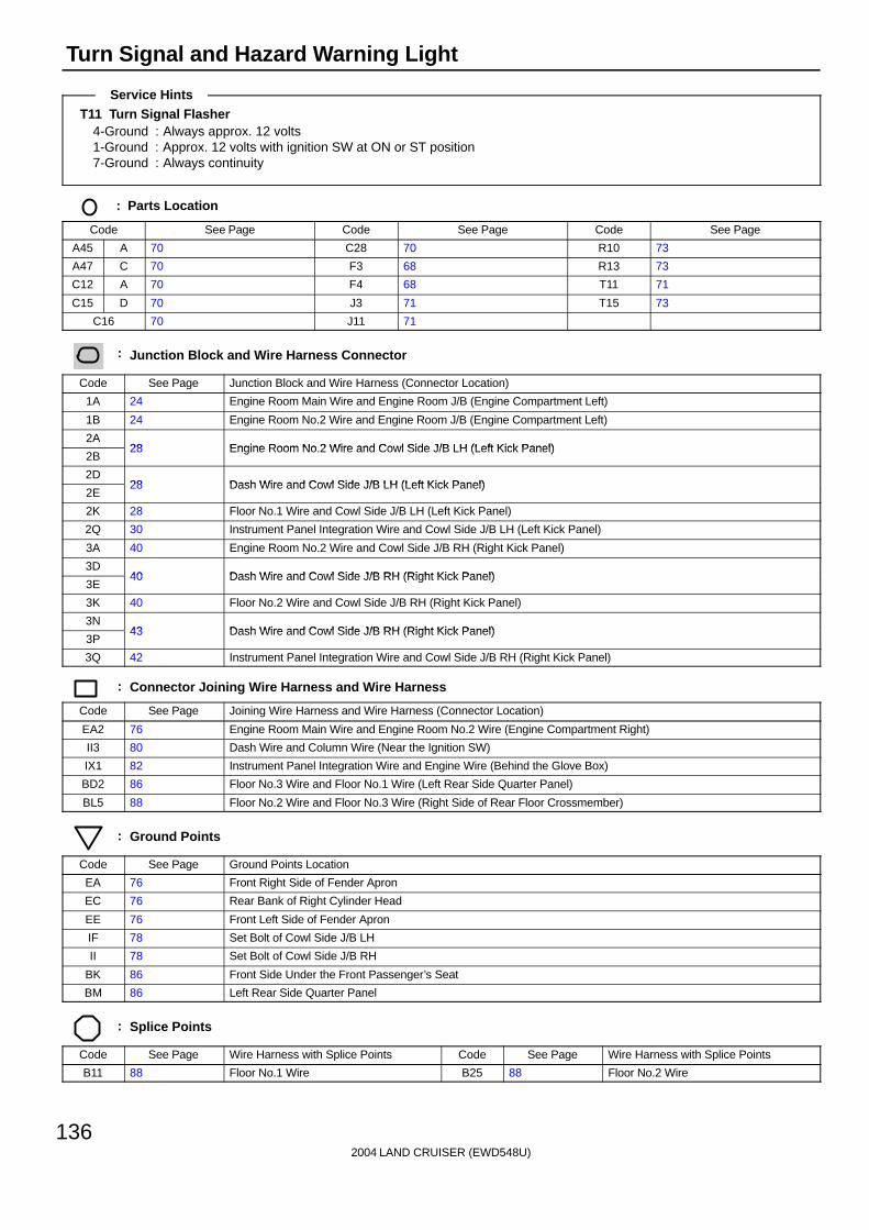
2004 LAND CRUISER (EWD548U)
136
Turn Signal and Hazard Warning Light
T11 Turn Signal Flasher4-Ground : Always approx. 12 volts1-Ground : Approx. 12 volts with ignition SW at ON or ST position7-Ground : Always continuity
: Parts Location
Code See Page Code See Page Code See Page
A45 A 70 C28 70 R10 73
A47 C 70 F3 68 R13 73
C12 A 70 F4 68 T11 71
C15 D 70 J3 71 T15 73
C16 70 J11 71
: Junction Block and Wire Harness Connector
Code See Page Junction Block and Wire Harness (Connector Location)
1A 24 Engine Room Main Wire and Engine Room J/B (Engine Compartment Left)
1B 24 Engine Room No.2 Wire and Engine Room J/B (Engine Compartment Left)
2A28 Engine Room No 2 Wire and Cowl Side J/B LH (Left Kick Panel)
2B28 Engine Room No.2 Wire and Cowl Side J/B LH (Left Kick Panel)
2D28 Dash Wire and Cowl Side J/B LH (Left Kick Panel)
2E28 Dash Wire and Cowl Side J/B LH (Left Kick Panel)
2K 28 Floor No.1 Wire and Cowl Side J/B LH (Left Kick Panel)
2Q 30 Instrument Panel Integration Wire and Cowl Side J/B LH (Left Kick Panel)
3A 40 Engine Room No.2 Wire and Cowl Side J/B RH (Right Kick Panel)
3D40 Dash Wire and Cowl Side J/B RH (Right Kick Panel)
3E40 Dash Wire and Cowl Side J/B RH (Right Kick Panel)
3K 40 Floor No.2 Wire and Cowl Side J/B RH (Right Kick Panel)
3N43 Dash Wire and Cowl Side J/B RH (Right Kick Panel)
3P43 Dash Wire and Cowl Side J/B RH (Right Kick Panel)
3Q 42 Instrument Panel Integration Wire and Cowl Side J/B RH (Right Kick Panel)
: Connector Joining Wire Harness and Wire Harness
Code See Page Joining Wire Harness and Wire Harness (Connector Location)
EA2 76 Engine Room Main Wire and Engine Room No.2 Wire (Engine Compartment Right)
II3 80 Dash Wire and Column Wire (Near the Ignition SW)
IX1 82 Instrument Panel Integration Wire and Engine Wire (Behind the Glove Box)
BD2 86 Floor No.3 Wire and Floor No.1 Wire (Left Rear Side Quarter Panel)
BL5 88 Floor No.2 Wire and Floor No.3 Wire (Right Side of Rear Floor Crossmember)
: Ground Points
Code See Page Ground Points Location
EA 76 Front Right Side of Fender Apron
EC 76 Rear Bank of Right Cylinder Head
EE 76 Front Left Side of Fender Apron
IF 78 Set Bolt of Cowl Side J/B LH
II 78 Set Bolt of Cowl Side J/B RH
BK 86 Front Side Under the Front Passenger’s Seat
BM 86 Left Rear Side Quarter Panel
: Splice Points
Code See Page Wire Harness with Splice Points Code See Page Wire Harness with Splice Points
B11 88 Floor No.1 Wire B25 88 Floor No.2 Wire
Service Hints

2004 LAND CRUISER (EWD548U)
137
Memo
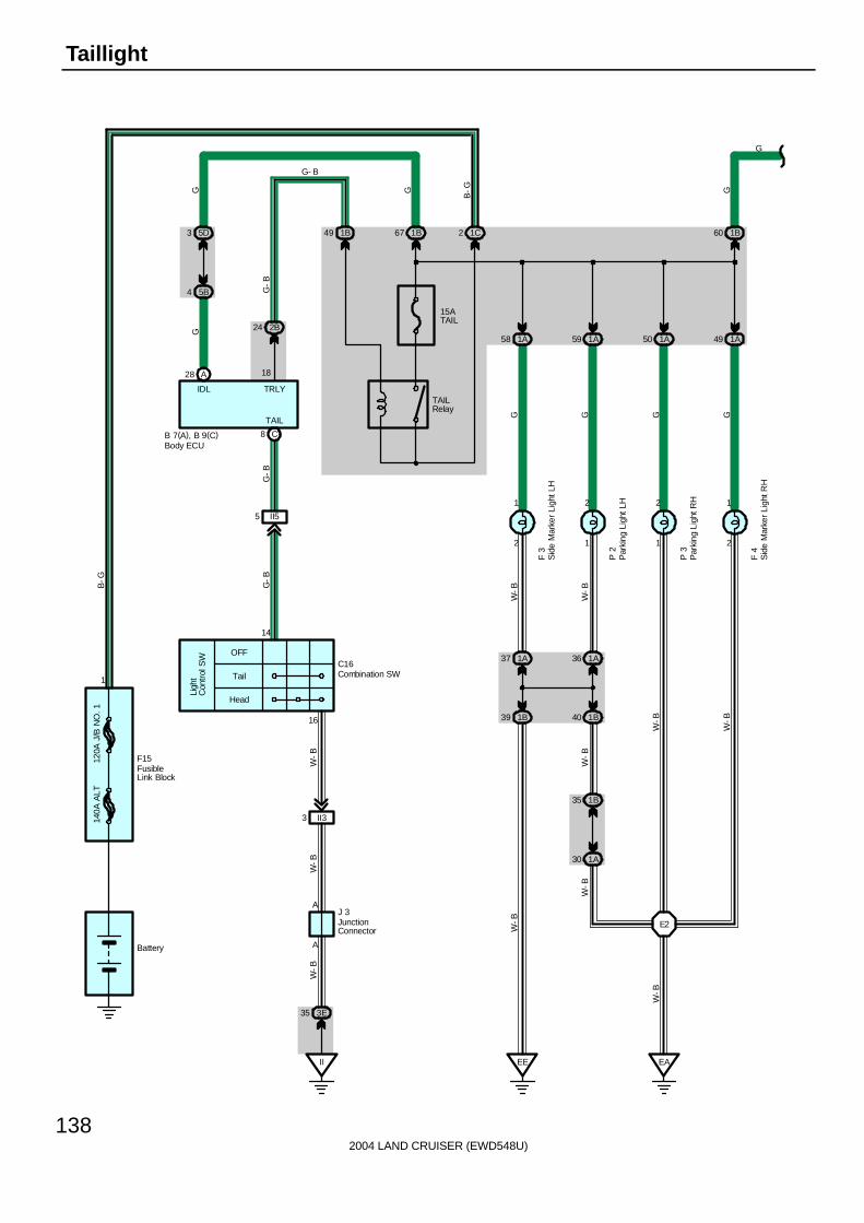
2004 LAND CRUISER (EWD548U)
138
Taillight
120A
J/B
NO
. 114
0A A
LT
1
OFF
Tail
Head
Ligh
tC
ontr
ol S
W
II
3E35
A
A
II33
14
16
II55
A28 18
2B24
W-B
W-B
W-B
G-B
G-B
C8
5B4
5D3
15ATAIL
1B671B49 1C2
1A58
2
1
1B39
1A37
EE
1A59
1
2
1B40
1A36
1A50
1
2
1A49
2
1
E2
1B60
C16
B 7(A), B 9(C)
J 3
F15
G
B-G
GG
B-G
G-B
G- B
W-B
W-B
W-B
W-B
W-B
W-B
GGGG
G
G
F 3
P 2
P 3
F 4
Battery
TRLYIDL
TAIL
TAILRelay
1A30
1B35
W-B
Combination SW
Sid
e M
arke
r Li
ght L
H
Sid
e M
arke
r Li
ght R
H
Par
king
Lig
ht L
H
Par
king
Lig
ht R
H
Body ECU
JunctionConnector
FusibleLink Block
EA
W-B

2004 LAND CRUISER (EWD548U)
139
3
6
B11
B11
BM
2
1
2
1
Tai
l
2
1
Tai
l
Tai
l
1
2
Tai
l
3
6
B11 B11
BP47
B15
BD213
B26
BQ28
B11 B11
BKBJ
B26B15
BH25
BP36 BQ210
W-B
W-B
W-B
W-B
W-B
W-B
W-B
W-B
W-B
W-B
W-B
W-B
W-B
W- B W- B
G G G G
G G G
GG
G
GG
G GGG
G
R10
L 1
R11
R13
L 2
R12
BL36
Lice
nse
Pla
te L
ight
LH
Lice
nse
Pla
te L
ight
RH
Rea
r C
ombi
natio
n Li
ght
LH
Rea
r C
ombi
natio
n Li
ght
LH
Rea
r C
ombi
natio
n Li
ght
RH
Rea
r C
ombi
natio
n Li
ght
RH
IA210
BH23BH14 (*1)
(*2)
BH23 (*1)(*2)
* 2 : w/o Navigation System* 1 : w/ Navigation System

2004 LAND CRUISER (EWD548U)
140
Taillight
C16 Combination SW14-16 : Closed with light control SW at TAIL or HEAD position
: Parts Location
Code See Page Code See Page Code See Page
B7 A 70 F15 68 P3 69
B9 C 70 J3 71 R10 73
C16 70 L1 72 R11 73
F3 68 L2 72 R12 73
F4 68 P2 69 R13 73
: Junction Block and Wire Harness Connector
Code See Page Junction Block and Wire Harness (Connector Location)
1A 24 Engine Room Main Wire and Engine Room J/B (Engine Compartment Left)
1B24 Engine Room No 2 Wire and Engine Room J/B (Engine Compartment Left)
1C24 Engine Room No.2 Wire and Engine Room J/B (Engine Compartment Left)
2B 28 Engine Room No.2 Wire and Cowl Side J/B LH (Left Kick Panel)
3E 40 Dash Wire and Cowl Side J/B RH (Right Kick Panel)
5B 56 Dash Wire and J/B No.5 (Behind the Combination Meter)
5D 56 Engine Room No.2 Wire and J/B No.5 (Behind the Combination Meter)
: Connector Joining Wire Harness and Wire Harness
Code See Page Joining Wire Harness and Wire Harness (Connector Location)
IA2 78 Engine Room No.2 Wire and Floor No.1 Wire (Left Kick Panel)
II380 Dash Wire and Column Wire (Near the Ignition SW)
II580 Dash Wire and Column Wire (Near the Ignition SW)
BD2 86 Floor No.3 Wire and Floor No.1 Wire (Left Rear Side Quarter Panel)
BH186 Pillar No 1 Wire and Back Door Upper Wire (Left Side of Back Door)
BH286 Pillar No.1 Wire and Back Door Upper Wire (Left Side of Back Door)
BL3 88 Floor No.2 Wire and Floor No.3 Wire (Right Side of Rear Floor Crossmember)
BP388 Pillar No 1 Wire and Floor No 1 Wire (Left Rear Side Quarter Panel)
BP488 Pillar No.1 Wire and Floor No.1 Wire (Left Rear Side Quarter Panel)
BQ2 88 Back Door Lower Wire and Floor No.1 Wire (Left Rear Side Quarter Panel)
: Ground Points
Code See Page Ground Points Location
EA 76 Front Right Side of Fender Apron
EE 76 Front Left Side of Fender Apron
II 78 Set Bolt of Cowl Side J/B RH
BJ 86 Under the Driver’s Seat
BK 86 Front Side Under the Front Passenger’s Seat
BM 86 Left Rear Side Quarter Panel
: Splice Points
Code See Page Wire Harness with Splice Points Code See Page Wire Harness with Splice Points
E2 76 Engine Room Main Wire B15 88 Back Door Upper Wire
B11 88 Floor No.1 Wire B26 88 Back Door Lower Wire
Service Hints

2004 LAND CRUISER (EWD548U)
141
Memo

2004 LAND CRUISER (EWD548U)
142
Illumination
10AGAUGE1
From Power Source System (See Page 94)
2Q65
IF11
SB
R-L
1
5
IF14
BS
B
IU34
B
2
IF211
W-B
SB
6
IF15
W-G
SB
3
IF28
W-R
SB
4
G
SB
SB
SB
IG T
ILL-TRETC
R 6Rheostat
120A
J/B
NO
. 1
1
140A
ALT
OFF
Tail
Head
Ligh
tC
ontr
ol S
W
II
3E35
A
A
II33
14
16
II55
TRLY
18
2B24W
-BW
-BW
-B
G-B
G-B
8 C
7. 5APANEL
1B631B49 1C2
J 3
B-G
F15
B-G
Battery
TAIL
TAILRelay
JunctionConnector
FusibleLink Block
G
G
Combination SWC16
B
18 C
TC
G- B
Body ECUB 9(C)
G
A
A
JunctionConnector
J14
SB
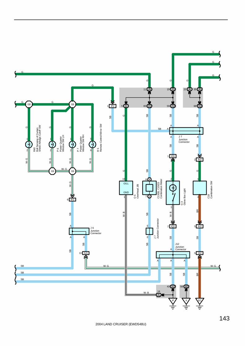
2004 LAND CRUISER (EWD548U)
143
2
1
R40
1
2 P 6
1
2 P 7
5
6 R 5
I18 I18
I19 I19
IF26
A
A A
B8
D7
E
E
2B11
2Q83
2D15
2Q55
IF
2Q43 3Q58
SB
SB
A A A
A
IQ12
1
2
IQ11
W-B
G
A
A
SB
SB
IF21
IX25
EC
IH25
IH22
A
AA
3D35
3Q68
SB
3K20
4
1
IU113
SB
SB
SB
W-G
G G G G
W-G
W-G
W-G
W-G
SB
G
G
W- G
SB
SB
SB
SB
J 6
C18
G 3
C13
( B) ,
C15
( D)
J 7
G G
SB
SB
G
G
SB
G
G
BR
SB
SB
SB
SB
BR
II
J 7
Com
bina
tion
Met
er
Com
bina
tion
SW
Glo
ve B
ox L
ight
Pow
er Q
uart
erW
indo
w S
W L
H
Pow
er Q
uart
erW
indo
w S
W R
H
Rem
ote
Con
trol
Mirr
or S
W
Junc
tion
Con
nect
or
JunctionConnector
JunctionConnector
JunctionConnector
J12
O 5
Ove
rhea
d J/
B
2L
14W- B
1
GND
W-B
2L5
16
GILL
GG
W- G
G
GG
W- G
Rol
l Sen
sing
of C
urta
inS
hiel
d A
irbag
s C
utof
f SW

2004 LAND CRUISER (EWD548U)
144
Illumination
4E9
4F1
W-G
BG
AG
5
4
1
2
M 9
M 5
R36
BG
4E8
12
2
J 9(A), J10(B)
G G G( *2)
( *1)
G
ILL+
ILL-
W-G
W-G
W-G
( *2)
( *1)
Mul
ti-D
ispl
ay
Mul
ti-D
ispl
ay
Rad
io a
nd P
laye
r
Junction Connector
Cen
ter
Clu
ster
Int
egra
tion
Pan
el
A/C
Con
trol
Ass
embl
y
GG
G
W-G
W-G
GG
7 4C
6 4C
C28
17
4
6 4F
4 4D
14 4A
A47
19
10
G
W- G
ILL-
ILL+

2004 LAND CRUISER (EWD548U)
145
JunctionConnector
Junction Connector
JunctionConnector
A/T
Shi
ft Le
ver
Illum
inat
ion
Sea
t H
eate
r S
W( F
ront
Pas
seng
er’
s S
eat)
Sea
t H
eate
r S
W( D
river
’s
Sea
t)
Ele
ctro
nica
lly C
ontr
olle
d T
rans
mis
sion
Pat
tern
Sel
ect S
W
Cig
aret
te L
ight
er Il
lum
inat
ion
A/C Amplifier(Rear)
Ash
tray
Illu
min
atio
n
J20(A), J21(B)
J18(A), J19(B)
A32
J23
22
10
G
W-G
W-G
W-G
W-G
W-G
GGGG
F
F
BK
W-G
E BE B
D A
GGE B
1
2
S 4
D A
E BG
1
2
5 4B
4 4B
S 3
6
1
1
2
14 4C
13 4C
W-B
E 4
16 4D
13 4DA
48
14
7
7 4D
3 4D
A29
W-B
11 4A
13 4A
C11
1
2
G
W-G
* 2 : w/o Navigation System* 1 : w/ Navigation System
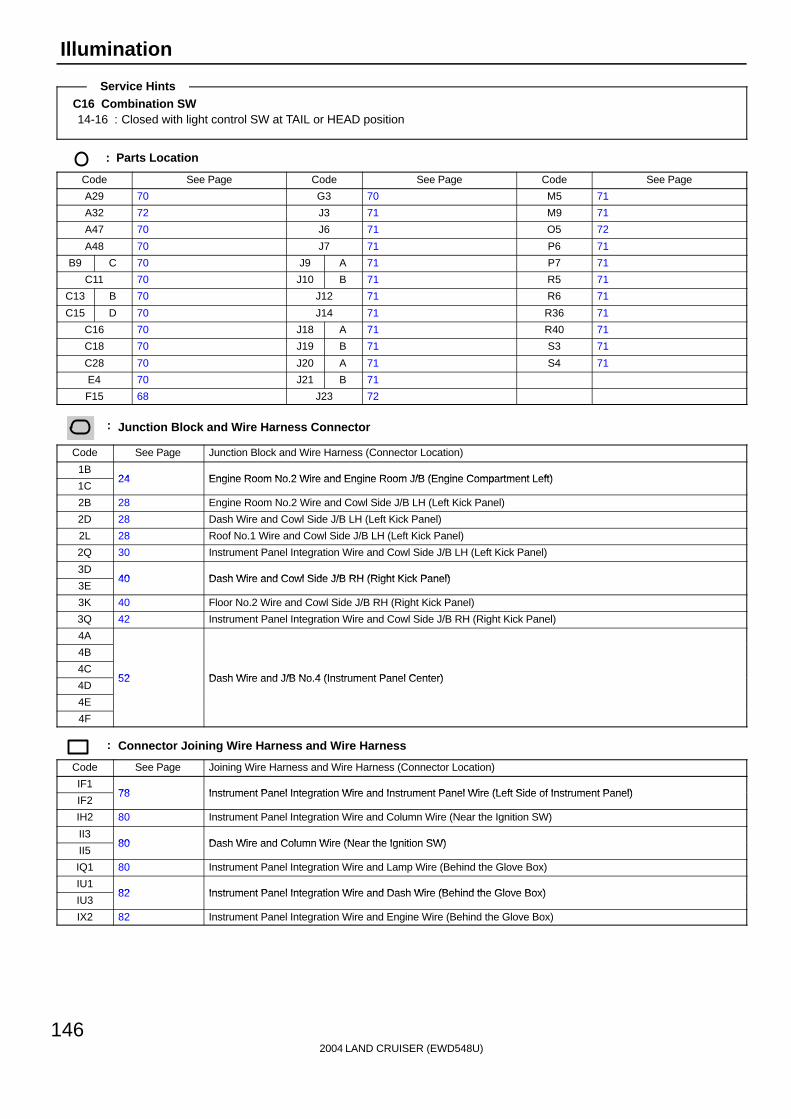
2004 LAND CRUISER (EWD548U)
146
Illumination
C16 Combination SW14-16 : Closed with light control SW at TAIL or HEAD position
: Parts Location
Code See Page Code See Page Code See Page
A29 70 G3 70 M5 71
A32 72 J3 71 M9 71
A47 70 J6 71 O5 72
A48 70 J7 71 P6 71
B9 C 70 J9 A 71 P7 71
C11 70 J10 B 71 R5 71
C13 B 70 J12 71 R6 71
C15 D 70 J14 71 R36 71
C16 70 J18 A 71 R40 71
C18 70 J19 B 71 S3 71
C28 70 J20 A 71 S4 71
E4 70 J21 B 71
F15 68 J23 72
: Junction Block and Wire Harness Connector
Code See Page Junction Block and Wire Harness (Connector Location)
1B24 Engine Room No 2 Wire and Engine Room J/B (Engine Compartment Left)
1C24 Engine Room No.2 Wire and Engine Room J/B (Engine Compartment Left)
2B 28 Engine Room No.2 Wire and Cowl Side J/B LH (Left Kick Panel)
2D 28 Dash Wire and Cowl Side J/B LH (Left Kick Panel)
2L 28 Roof No.1 Wire and Cowl Side J/B LH (Left Kick Panel)
2Q 30 Instrument Panel Integration Wire and Cowl Side J/B LH (Left Kick Panel)
3D40 Dash Wire and Cowl Side J/B RH (Right Kick Panel)
3E40 Dash Wire and Cowl Side J/B RH (Right Kick Panel)
3K 40 Floor No.2 Wire and Cowl Side J/B RH (Right Kick Panel)
3Q 42 Instrument Panel Integration Wire and Cowl Side J/B RH (Right Kick Panel)
4A
4B
4C52 Dash Wire and J/B No 4 (Instrument Panel Center)
4D52 Dash Wire and J/B No.4 (Instrument Panel Center)
4E
4F
: Connector Joining Wire Harness and Wire Harness
Code See Page Joining Wire Harness and Wire Harness (Connector Location)
IF178 Instrument Panel Integration Wire and Instrument Panel Wire (Left Side of Instrument Panel)
IF278 Instrument Panel Integration Wire and Instrument Panel Wire (Left Side of Instrument Panel)
IH2 80 Instrument Panel Integration Wire and Column Wire (Near the Ignition SW)
II380 Dash Wire and Column Wire (Near the Ignition SW)
II580 Dash Wire and Column Wire (Near the Ignition SW)
IQ1 80 Instrument Panel Integration Wire and Lamp Wire (Behind the Glove Box)
IU182 Instrument Panel Integration Wire and Dash Wire (Behind the Glove Box)
IU382 Instrument Panel Integration Wire and Dash Wire (Behind the Glove Box)
IX2 82 Instrument Panel Integration Wire and Engine Wire (Behind the Glove Box)
Service Hints
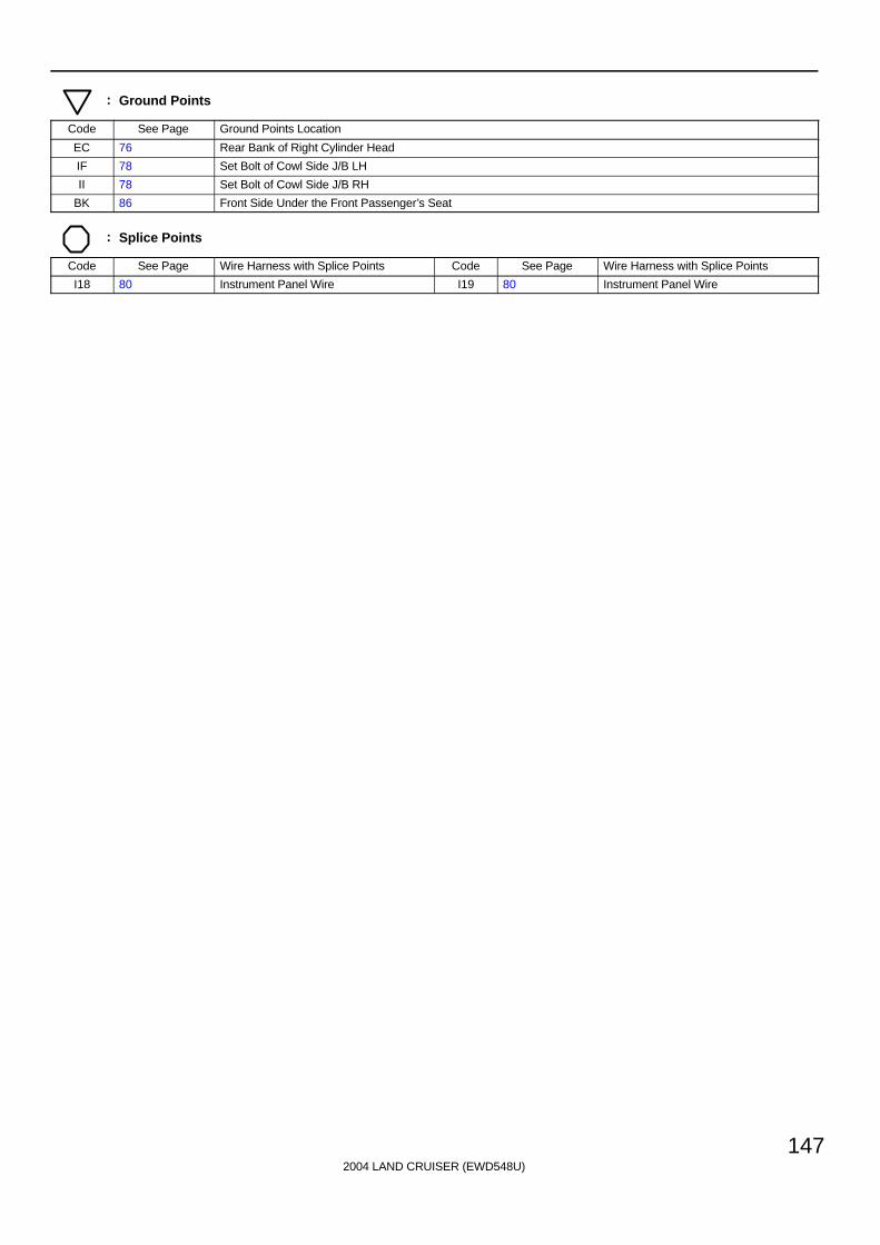
2004 LAND CRUISER (EWD548U)
147
: Ground Points
Code See Page Ground Points Location
EC 76 Rear Bank of Right Cylinder Head
IF 78 Set Bolt of Cowl Side J/B LH
II 78 Set Bolt of Cowl Side J/B RH
BK 86 Front Side Under the Front Passenger’s Seat
: Splice Points
Code See Page Wire Harness with Splice Points Code See Page Wire Harness with Splice Points
I18 80 Instrument Panel Wire I19 80 Instrument Panel Wire

2004 LAND CRUISER (EWD548U)
148
Interior Light
From Power Source System (See Page 94)
25A
DO
OR
B 7(A), B 8(B), B 9(C)
A3
1 5
2 3
2G1
2K9 2Q79
1
4
3
OF
F
DO
OR
ON
BR18
BR19BR111
F10
G- W
SB
L- Y
R-W
L-Y
SB
RW
W W
W-B
DO
ME
Rel
ay
LMRY
W- B
R
G-W
B 7
B 7
IF
2L11
W-B
7. 5
A A
CC
22
ACC
R
12
BDR110ADOME
3Q45 3Q17
2L8
W- B
SB
SB
W-B
Body ECU
Front Interior LightRear Personal Light

2004 LAND CRUISER (EWD548U)
149
BR15
BR14
2L18
2E12
6
2
2E15
2L3
3Q80
3K22
V 7
R27
T10
G- W
SB
L- Y
R
WG
-Y
G-W
R
SB
L- Y
G- Y
R R SB
B 7(A), B 8(B), B 9(C)
ILE
13
2
1 1
OF
F
DO
OR
ON
W
2
B 7
RR
W-B
W- B
R
3J7
G- Y
R
R
R
R
V 6
R
B 7
B 7
2
1
RW
-B
W- B
F11
2
1
B 7
B 7
RW
-B
R
G-W
2E22 2K22 2I4 2Q27
Fron
t P
erso
nal L
ight
Rea
r In
terio
r Li
ght
Igni
tion
Key
Cyl
inde
r Li
ght
Van
ity L
ight
LH
Van
ity L
ight
RH
Body ECU
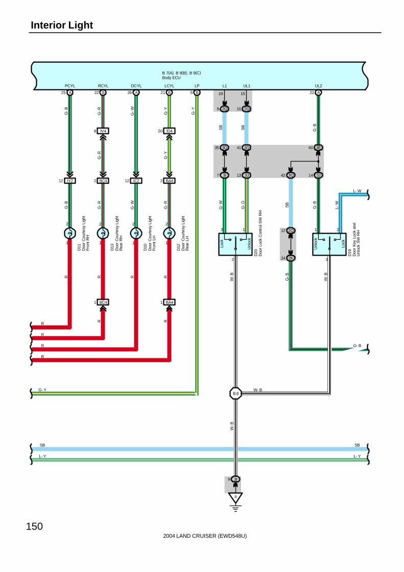
2004 LAND CRUISER (EWD548U)
150
Interior Light
L- Y
B 7(A), B 8(B), B 9(C)
SB
L- Y
D12
D10
D13
D11
1
2 2
1 1
2
1
2
IY212 BC42 IC212 BA42
IV48 ID420
B22 B21A26A25
BC41 BA41
R R R RG
-R
G-W
G-R
G-B
G-R
G-Y
G-Y
G-R
G-B
G-W
PCYL RCYL DCYL LCYL
RR
SB
R
R
R
R
21
3
Unl
ock
Lock
24 2K
12 2Q
14 3J
40 3E
42 3Q
A22
D19
G-B
SB
G-B
L-W
G-B
W-B
UL2
Unl
ock
Lock
3 1
3Q35
3I7 3J13
2Q9 2Q10
3Q41
19 15
L1 UL1
G-W
G-O
SB
SB
W-B
2
L- W
G- B
B6
LP
G- Y
G-Y
II
9 3I
B 8
W-B
W- B
D20
Doo
r C
ourte
sy L
ight
Fron
t LH
Doo
r C
ourte
sy L
ight
Fron
t RH
Doo
r C
ourte
sy L
ight
Rea
r LH
Doo
r C
ourte
sy L
ight
Rea
r R
H
Doo
r K
ey L
ock
and
Unl
ock
SW
RH
Doo
r Lo
ck C
ontr
ol S
W R
H
Body ECU
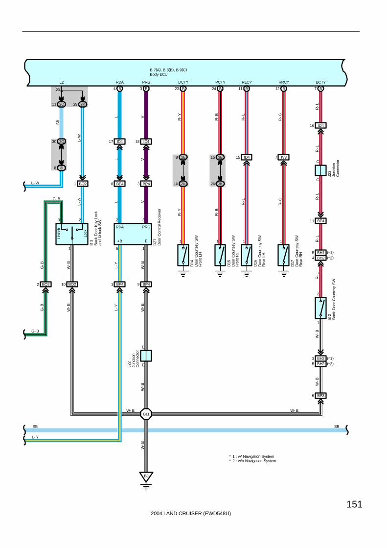
2004 LAND CRUISER (EWD548U)
151
B 7(A), B 8(B), B 9(C)
Lock
Unl
ock
1
3 2
BQ22 BQ210 BP41 BP49
2K292Q11
BP48 BP43
ID417 ID418
B4 B3
D27
B 3
G-B
W-B
L-Y
W-B
L V
L V
L V
G-B
W-B
L-Y
W-B
L-WG- B
L2 RDA PRG
20
5 1
2 3
BQ21
L-W
BJ
W-B
W- B
E
EJ22
B11
W-B
8 3I
30 3Q
G- B
L- W
SB
L- Y
SB
1 1 1 1
1
2
10 2K
8 2E
26 3K
15 3E
B23 B24 B11 B12
ID415 IV37
ID416
B7
C
C
BP411
BH24
D14
D15
D16
D17
J22
B 2
R-Y
R-B
R-L
R-G
R-Y
R-B
R-L
R-G
R-L
R-L
R-L
R-L
R-L
W-B
DCTY RLCY RRCY BCTYPCTY
BP36
BH25
W-B
W- B
SB
Bac
k D
oor
Cou
rtes
y S
W
Bac
k D
oor
Key
Loc
kan
d U
nloc
k S
W
Doo
r C
ourt
esy
SW
Fron
t LH
Doo
r C
ourt
esy
SW
Fron
t R
H
Doo
r C
ourt
esy
SW
Rea
r LH
Doo
r C
ourt
esy
SW
Rea
r R
H
Body ECU
Junc
tion
Con
nect
or
Junc
tion
Con
nect
or
Doo
r C
ontr
ol R
ecei
ver
RDA PRG
+B E
BH23 (*1)(*2)
BH15 (*1)(*2)
* 2 : w/o Navigation System* 1 : w/ Navigation System

2004 LAND CRUISER (EWD548U)
152
Interior Light
B 7(A), B 8(B), B 9(C)
SB
Doo
r
C12
( A) ,
C15
( D)
D14
A3
9 3Q
19 3E
C12
SB
G-Y
DRLP
SB
Com
bina
tion
Met
erBody ECU
LL
2I
10A
EC
U-I
G1
L-W
IG
GND2
IF
16 4
GND1
2I
SIG
20
1 71
SB
9
CPUB
L
SB
L-W
22 2Q2
10A
EC
U-B
2
3Q
11
BECU
B 2
W-B
W- B W- B
W-B
W-B
G-B
L-W
KEYEGNDKUL
24 A
IC211
7
MPX1
BB
MPX1
20A
P/W
(FL
)
3E1
2E42
2I7
KL
32144
D18
P12
BDR
10
Unl
ock
Lock
3
2 1
2I
8
From Power Source System (See Page 94)
B 2
W-B
Doo
r K
ey L
ock
and
Unl
ock
SW
LH
Power Window Master SWB
-WB
-W
10
SIG
IU315
IL31
E
E
C26
31
T 5
MPX1
MPX3
BS
BS
BB
TheftDeterrentECU
Junc
tion
Con
nect
or
J14
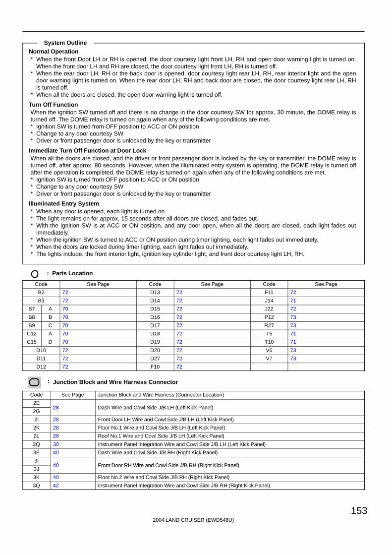
2004 LAND CRUISER (EWD548U)
153
Normal Operation∗ When the front Door LH or RH is opened, the door courtesy light front LH, RH and open door warning light is turned on.
When the front door LH and RH are closed, the door courtesy light front LH, RH is turned off.∗ When the rear door LH, RH or the back door is opened, door courtesy light rear LH, RH, rear interior light and the open
door warning light is turned on. When the rear door LH, RH and back door are closed, the door courtesy light rear LH, RHis turned off.
∗ When all the doors are closed, the open door warning light is turned off.
Turn Off FunctionWhen the ignition SW turned off and there is no change in the door courtesy SW for approx. 30 minute, the DOME relay isturned off. The DOME relay is turned on again when any of the following conditions are met.∗ Ignition SW is turned from OFF position to ACC or ON position∗ Change to any door courtesy SW∗ Driver or front passenger door is unlocked by the key or transmitter
Immediate Turn Off Function at Door LockWhen all the doors are closed, and the driver or front passenger door is locked by the key or transmitter, the DOME relay isturned off, after approx. 80 seconds. However, when the illuminated entry system is operating, the DOME relay is turned offafter the operation is completed. the DOME relay is turned on again when any of the following conditions are met.∗ Ignition SW is turned from OFF position to ACC or ON position∗ Change to any door courtesy SW∗ Driver or front passenger door is unlocked by the key or transmitter
Illuminated Entry System∗ When any door is opened, each light is turned on.∗ The light remains on for approx. 15 seconds after all doors are closed, and fades out.∗ With the ignition SW is at ACC or ON position, and any door open, when all the doors are closed, each light fades out
immediately.∗ When the ignition SW is turned to ACC or ON position during timer lighting, each light fades out immediately.∗ When the doors are locked during timer lighting, each light fades out immediately.∗ The lights include, the front interior light, ignition key cylinder light, and front door courtesy light LH, RH.
: Parts Location
Code See Page Code See Page Code See Page
B2 72 D13 72 F11 72
B3 72 D14 72 J14 71
B7 A 70 D15 72 J22 72
B8 B 70 D16 72 P12 73
B9 C 70 D17 72 R27 73
C12 A 70 D18 72 T5 71
C15 D 70 D19 72 T10 71
D10 72 D20 72 V6 73
D11 72 D27 72 V7 73
D12 72 F10 72
: Junction Block and Wire Harness Connector
Code See Page Junction Block and Wire Harness (Connector Location)
2E28 Dash Wire and Cowl Side J/B LH (Left Kick Panel)
2G28 Dash Wire and Cowl Side J/B LH (Left Kick Panel)
2I 28 Front Door LH Wire and Cowl Side J/B LH (Left Kick Panel)
2K 28 Floor No.1 Wire and Cowl Side J/B LH (Left Kick Panel)
2L 28 Roof No.1 Wire and Cowl Side J/B LH (Left Kick Panel)
2Q 30 Instrument Panel Integration Wire and Cowl Side J/B LH (Left Kick Panel)
3E 40 Dash Wire and Cowl Side J/B RH (Right Kick Panel)
3I40 Front Door RH Wire and Cowl Side J/B RH (Right Kick Panel)
3J40 Front Door RH Wire and Cowl Side J/B RH (Right Kick Panel)
3K 40 Floor No.2 Wire and Cowl Side J/B RH (Right Kick Panel)
3Q 42 Instrument Panel Integration Wire and Cowl Side J/B RH (Right Kick Panel)
System Outline

2004 LAND CRUISER (EWD548U)
154
Interior Light
: Connector Joining Wire Harness and Wire Harness
Code See Page Joining Wire Harness and Wire Harness (Connector Location)
IC2 78 Front Door LH Wire and Dash Wire (Left Kick Panel)
ID4 78 Dash Wire and Floor No.1 Wire (Left Kick Panel)
IL3 80 Instrument Panel Integration Wire and Computer Wire (Instrument Panel Center)
IU3 82 Instrument Panel Integration Wire and Dash Wire (Behind the Glove Box)
IV382 Dash Wire and Floor No 2 Wire (Right Kick Panel)
IV482 Dash Wire and Floor No.2 Wire (Right Kick Panel)
IY2 82 Front Door RH Wire and Dash Wire (Right Kick Panel)
BA4 86 Rear Door LH Wire and Floor No.1 Wire (Left Side of Center Pillar)
BC4 86 Rear Door RH Wire and Floor No.2 Wire (Right Side of Center Pillar)
BH186 Pillar No 1 Wire and Back Door Upper Wire (Left Side of Back Door)
BH286 Pillar No.1 Wire and Back Door Upper Wire (Left Side of Back Door)
BP388 Pillar No 1 Wire and Floor No 1 Wire (Left Rear Side Quarter Panel)
BP488 Pillar No.1 Wire and Floor No.1 Wire (Left Rear Side Quarter Panel)
BQ2 88 Back Door Lower Wire and Floor No.1 Wire (Left Rear Side Quarter Panel)
BR1 88 Roof No.3 Wire and Roof No.1 Wire (Front Side of Roof)
: Ground Points
Code See Page Ground Points Location
IF78 Set Bolt of Cowl Side J/B LH
IG78 Set Bolt of Cowl Side J/B LH
II 78 Set Bolt of Cowl Side J/B RH
BJ 86 Under the Driver’s Seat
: Splice Points
Code See Page Wire Harness with Splice Points Code See Page Wire Harness with Splice Points
B2 88 Front Door LH Wire B8 88 Front Door RH Wire
B7 88 Roof No.1 Wire B11 88 Floor No.1 Wire

2004 LAND CRUISER (EWD548U)
155
Memo
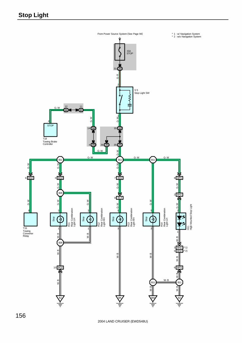
2004 LAND CRUISER (EWD548U)
156
Stop Light
15ASTOP
From Power Source System (See Page 94)
2D31
1
2
2D35
2K352E263M4
3M14
3
5
R13
Sto
p
BK
3
1
R12
Sto
p
3
1
R11
Sto
p
5
3
R10
Sto
p
2
1
H11
BJBMBJ
BH25
BL48
BD27 BP38BQ23
BH22
BP36BQ210
G-W
G-W
G-W
G-R
G-W
G-W
G-W
G-W
G-W
G-W
G-W
G-W
G-W
G-W
W-B
W-B
W-B
W-B
W-B
W-B
W-BW
-BW
-B
W-B
W-B
G- WG- W
G- W
G-W
S 5
G- W
W- B
B11 B11B11
B26
B26
B11B11
Hig
h M
ount
ed S
top
Ligh
t
Rea
r C
ombi
natio
nLi
ght L
H
Rea
r C
ombi
natio
nLi
ght L
H
Rea
r C
ombi
natio
nLi
ght R
H
Rea
r C
ombi
natio
nLi
ght R
H
Stop Light SW
6C
11
6A
12
4
G- W
STOP
Towing BrakeController
T18
BD26
8
TowingConverterRelay
T15
G-W
BH23 (*1)(*2)
* 2 : w/o Navigation System* 1 : w/ Navigation System

2004 LAND CRUISER (EWD548U)
157
S5 Stop Light SW2-1 : Closed with brake pedal depressed
: Parts Location
Code See Page Code See Page Code See Page
H11 72 R12 73 T15 73
R10 73 R13 73 T18 71
R11 73 S5 71
: Junction Block and Wire Harness Connector
Code See Page Junction Block and Wire Harness (Connector Location)
2D28 Dash Wire and Cowl Side J/B LH (Left Kick Panel)
2E28 Dash Wire and Cowl Side J/B LH (Left Kick Panel)
2K 28 Floor No.1 Wire and Cowl Side J/B LH (Left Kick Panel)
3M 43 Dash Wire and Cowl Side J/B RH (Right Kick Panel)
6A60 Dash Wire and J/B No 6 (Behind the Grove Box)
6C60 Dash Wire and J/B No.6 (Behind the Grove Box)
: Connector Joining Wire Harness and Wire Harness
Code See Page Joining Wire Harness and Wire Harness (Connector Location)
BD2 86 Floor No.3 Wire and Floor No.1 Wire (Left Rear Side Quarter Panel)
BH2 86 Pillar No.1 Wire and Back Door Upper Wire (Left Side of Back Door)
BL4 88 Floor No.2 Wire and Floor No.3 Wire (Right Side of Rear Floor Crossmember)
BP3 88 Pillar No.1 Wire and Floor No.1 Wire (Left Rear Side Quarter Panel)
BQ2 88 Back Door Lower Wire and Floor No.1 Wire (Left Rear Side Quarter Panel)
: Ground Points
Code See Page Ground Points Location
BJ 86 Under the Driver’s Seat
BK 86 Front Side Under the Front Passenger’s Seat
BM 86 Left Rear Side Quarter Panel
: Splice Points
Code See Page Wire Harness with Splice Points Code See Page Wire Harness with Splice Points
B11 88 Floor No.1 Wire B26 88 Back Door Lower Wire
Service Hints

2004 LAND CRUISER (EWD548U)
158
Trailer Towing
10AGAUGE2
3E3
Ib26
R-L
R-L
IN214
R-L
R-B
IN24
R-B
Ib24
R-B
2E38
2K39
BD212
BX17
4
R-B
R-B
Y
30ABATTCHARGE
From Power Source System (See Page 94)
2K5
BD28
BX12
1
GG
G
30ATOWINGTAIL
1B69
IA21
G
BD215
BX18
30ATOWING
1B72
2
BX11 BX14
BL51BD29 BD26BD211
IA217
3K6 2K40
3E31 2E5
2 3
4 2
1 3 9 8
G-Y
G-B
B
G-Y
B
BL
G-B
G-W
G-B
G-W
G-Y
3 5
R BR
G-Y
G-B
35 2K
2D35
2E26
BX13
B16
6
W-B
W
W- B
G- W
G- W
G-W
G-W
W- B
6
T11
T12
T15
P 1
B
B
LR LL
W-B
Par
k/N
eutr
alP
ositi
on S
WTurn SignalFlasher
Trailer Socket
Tow
ing
Con
vert
er R
elay
R
3
2
3 1
5 2
B24
B
Tow
ing
Hitc
h R
elay
T23
B
L
W-B
W- B

2004 LAND CRUISER (EWD548U)
159
7
BX15
BD217
ID416A12
6C11
2 2A
6 2E4 2E
2A8G W
G W
15ATAIL
1B58
30ATOWING BRK
1B61
4
G-W
4 3M
3M14
G-W
2
1
15ASTOP
From Power Source System (See Page 94)
2D31
B16
BJ
BD210
BM BK II
3E34
BL112
B11
5 2
1 3
W-L
W-L
W-B
W-L
W-B
L
W-B
W-B
W-B
W-B
W-BW- B
G- W
G- W
W- B
G- W
G- R
G-R
T18
S 5
W- B
GNDBRKSTOP
TAIL +B
Sto
p Li
ght
SW
Towing Brake Controller
T12Trailer Socket
E E
JunctionConnector
J22
W- BW- B

2004 LAND CRUISER (EWD548U)
160
Trailer Towing
T15 Towing Converter Relay1-Ground : Always approx. 12 volts6-Ground : Always continuity
S5 Stop Light SW2-1 : Closed with brake pedal depressed
: Parts Location
Code See Page Code See Page Code See Page
J22 72 T11 71 T18 71
P1 69 T12 73 T23 73
S5 71 T15 73
: Junction Block and Wire Harness Connector
Code See Page Junction Block and Wire Harness (Connector Location)
1B 24 Engine Room No.2 Wire and Engine Room J/B (Engine Compartment Left)
2A 28 Engine Room No.2 Wire and Cowl Side J/B LH (Left Kick Panel)
2D28 Dash Wire and Cowl Side J/B LH (Left Kick Panel)
2E28 Dash Wire and Cowl Side J/B LH (Left Kick Panel)
2K 28 Floor No.1 Wire and Cowl Side J/B LH (Left Kick Panel)
3E 40 Dash Wire and Cowl Side J/B RH (Right Kick Panel)
3K 40 Floor No.2 Wire and Cowl Side J/B RH (Right Kick Panel)
3M 43 Dash Wire and Cowl Side J/B RH (Right Kick Panel)
6A60 Dash Wire and J/B No 6 (Behind the Grove Box)
6C60 Dash Wire and J/B No.6 (Behind the Grove Box)
: Connector Joining Wire Harness and Wire Harness
Code See Page Joining Wire Harness and Wire Harness (Connector Location)
IA2 78 Engine Room No.2 Wire and Floor No.1 Wire (Left Kick Panel)
ID4 78 Dash Wire and Floor No.1 Wire (Left Kick Panel)
IN2 80 Engine Wire and Dash Wire (Behind the Glove Box)
Ib2 84 Dash Wire and Dash Wire (Behind the Combination Meter)
BD2 86 Floor No.3 Wire and Floor No.1 Wire (Left Rear Side Quarter Panel)
BL188 Floor No 2 Wire and Floor No 3 Wire (Right Side of Rear Floor Crossmember)
BL588 Floor No.2 Wire and Floor No.3 Wire (Right Side of Rear Floor Crossmember)
BX1 88 Frame No.4 Wire and Floor No.3 Wire (Left Side of Rear Floor Crossmember)
: Ground Points
Code See Page Ground Points Location
II 78 Set Bolt of Cowl Side J/B RH
BJ 86 Under the Driver’s Seat
BK 86 Front Side Under the Front Passenger’s Seat
BM 86 Left Rear Side Quarter Panel
: Splice Points
Code See Page Wire Harness with Splice Points Code See Page Wire Harness with Splice Points
B11 88 Floor No.1 Wire B24 88 Floor No.1 Wire
B16 88 Floor No.3 Wire
Service Hints

2004 LAND CRUISER (EWD548U)
161
Memo
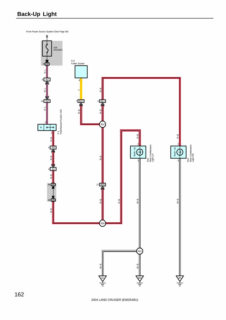
2004 LAND CRUISER (EWD548U)
162
Back-Up Light
10AGAUGE2
From Power Source System (See Page 94)
3E3
Ib26
R-L
R-L
IN214
2
R-L
R-B
IN24
R-B
Ib24
R-B
2E38
2K39
BD212
3
2
3
2
BM BK
B11
BJ
Bac
k-U
p
Bac
k-U
p
B16
BL16
B14
R-B
R-B
R-B
W-B
W-B
W-B
W-B
R-B
R-B
R-B
R-B
R-B
P 1
Par
k/N
eutr
al P
ositi
on S
W
Rea
r C
ombi
natio
nLi
ght
LH
R10
Rea
r C
ombi
natio
nLi
ght
RH
R13
BX17
R-B
Y4
Trailer SocketT12
R
3

2004 LAND CRUISER (EWD548U)
163
P1 Park/Neutral Position SW3-2 : Closed with shift lever at R position
: Parts Location
Code See Page Code See Page Code See Page
P1 69 R13 73
R10 73 T12 73
: Junction Block and Wire Harness Connector
Code See Page Junction Block and Wire Harness (Connector Location)
2E 28 Dash Wire and Cowl Side J/B LH (Left Kick Panel)
2K 28 Floor No.1 Wire and Cowl Side J/B LH (Left Kick Panel)
3E 40 Dash Wire and Cowl Side J/B RH (Right Kick Panel)
: Connector Joining Wire Harness and Wire Harness
Code See Page Joining Wire Harness and Wire Harness (Connector Location)
IN2 80 Engine Wire and Dash Wire (Behind the Glove Box)
Ib2 84 Dash Wire and Dash Wire (Behind the Combination Meter)
BD2 86 Floor No.3 Wire and Floor No.1 Wire (Left Rear Side Quarter Panel)
BL1 88 Floor No.2 Wire and Floor No.3 Wire (Right Side of Rear Floor Crossmember)
BX1 88 Frame No.4 Wire and Floor No.3 Wire (Left Side of Rear Floor Crossmember)
: Ground Points
Code See Page Ground Points Location
BJ 86 Under the Driver’s Seat
BK 86 Front Side Under the Front Passenger’s Seat
BM 86 Left Rear Side Quarter Panel
: Splice Points
Code See Page Wire Harness with Splice Points Code See Page Wire Harness with Splice Points
B11 88 Floor No.1 Wire B16 88 Floor No.3 Wire
B14 88 Floor No.2 Wire
Service Hints

2004 LAND CRUISER (EWD548U)
164
Automatic Light Control
B 7(A), B 9(C)
5B4
5D3
15A
AM
2
From Power Source System (See Page 94)
1C2
TA
IL R
elay
G
15A
TA
IL
120AJ/BNO. 1
140AALT
F15
Battery
1
1B67
A28
2B241B49
HE
AD
Rel
ay
22 1B
5 2B11 2E
C20
Head
Tail
OFF
Ligh
t Con
trol
SW
Auto
II33
16
A
A
II
3E35
J 3
W-B
W-B
W-B
C3
II51
IU317IU318 IU316
C6 C21 C4
CLTSCLTB CLTE
43 6
B
A31
B
Y
SB
SB
SB
YR BR
Y
CLTSCLTB CLTE
E
E
C5
3E26
3E21
3D13
4A17
4A8
A17 (*1)
B3 (*2)
10A
EC
U-I
G1
7. 5
A A
CC
B-G
G-B
G-B
G
W-L
G
W-L
W-L
W-L
IDLTRLY
18
3
TCDR(*1)TC(*2)
ACAN
A47
M 5
( A) ,
M 9
( B)
R-W
R-W
R-W
R-W
R-W
17
HRLYHF2
J 9
G-O
G-O
A
12
C16
10A
EC
U-B
2
SB
2Q22
3Q71
11 22 10
SIGACCBECUTC
C18
4 IF1
IU34
BS
B
TC
5
R 6
B
* 2 : w/o Navigation System* 1 : w/ Navigation System
Automatic LightControl Sensor
Combination SW
Mul
ti-D
ispl
ay
Rhe
osta
t
A/C
Con
trol
Ass
embl
y
Body ECU
Junc
tion
Con
nect
or
Junc
tion
Con
nect
or
FusibleLink Block
16
GND1 GND2
4
IGIF
BRR
25A
DO
OR
12
BDR1
IM21 IM23 IM22

2004 LAND CRUISER (EWD548U)
165
The automatic light control system works when the light control SW is turned to AUTO. The automatic light control sensordetects the brightness around the vehicle. By this function, the system automatically turns the taillight and headlight on if thebrightness is below the regular level and turns the taillight and headlight off when the surroundings become brighter than theregular level.
Body ECU11, 12-Ground : Always approx. 12 volts
22-Ground : Approx. 12 volts with ignition SW at ACC or ON position10-Ground : Approx. 12 volts with ignition SW at ON or ST position
4, 16-Ground : Always continuity
: Parts Location
Code See Page Code See Page Code See Page
A31 70 C16 70 M5 A 71
A47 70 F15 68 M9 B 71
B7 A 70 J3 71 R6 71
B9 C 70 J9 71
: Junction Block and Wire Harness Connector
Code See Page Junction Block and Wire Harness (Connector Location)
1B24 Engine Room No 2 Wire and Engine Room J/B (Engine Compartment Left)
1C24 Engine Room No.2 Wire and Engine Room J/B (Engine Compartment Left)
2B 28 Engine Room No.2 Wire and Cowl Side J/B LH (Left Kick Panel)
2E 28 Dash Wire and Cowl Side J/B LH (Left Kick Panel)
2Q 30 Instrument Panel Integration Wire and Cowl Side J/B LH (Left Kick Panel)
3D40 Dash Wire and Cowl Side J/B RH (Right Kick Panel)
3E40 Dash Wire and Cowl Side J/B RH (Right Kick Panel)
3Q 42 Instrument Panel Integration Wire and Cowl Side J/B RH (Right Kick Panel)
4A 52 Dash Wire and J/B No.4 (Instrument Panel Center)
5B 56 Dash Wire and J/B No.5 (Behind the Combination Meter)
5D 56 Engine Room No.2 Wire and J/B No.5 (Behind the Combination Meter)
: Connector Joining Wire Harness and Wire Harness
Code See Page Joining Wire Harness and Wire Harness (Connector Location)
IF1 78 Instrument Panel Integration Wire and Instrument Panel Wire (Left Side of Instrument Panel)
II380 Dash Wire and Column Wire (Near the Ignition SW)
II580 Dash Wire and Column Wire (Near the Ignition SW)
IM2 80 Instrument Panel Integration Wire and Instrument Panel No.3 Wire (Right Side of Instrument Panel)
IU3 82 Instrument Panel Integration Wire and Dash Wire (Behind the Glove Box)
: Ground Points
Code See Page Ground Points Location
IF78 Set Bolt of Cowl Side J/B LH
IG78 Set Bolt of Cowl Side J/B LH
II 78 Set Bolt of Cowl Side J/B RH
System Outline
Service Hints

2004 LAND CRUISER (EWD548U)
166
Light Auto Turn Off
B 7(A), B 8(B), B 9(C)
5B4
5D3
15A
AM
2
1C2
TA
IL R
elay
G
15A
TA
IL
120AJ/BNO. 1
140AALT
F15
Battery
1
1B67
A28
2B241B49
3
HE
AD
Rel
ay
22 1B
5 2B11 2E
C20
Head
Tail
OFF
Ligh
t Con
trol
SW
Auto
II33
16
A
A
II
3E35
J 3
W-B
W-B
W-B
C8
II55
E
E
10A
EC
U-I
G1
7. 5
A A
CC
B-G
G-B
G-B
G
G
IDLTRLY
18
R-W
R-W
R-W
R-W
R-W
17
HRLYHF2
J 9
G-B
G-B
TAIL
14
C16
10A
EC
U-B
2
SB
2Q22
3Q71
11 22 10
SIGACCBECU
From Power Source System (See Page 94)
25A
DO
OR
12
BDR1
1
10 2K
8 2E
B23
D14
R-Y
R-Y
DCTY
II52
13
HEAD
C1
R-W
R-W
Combination SW
Doo
r C
ourte
sy S
WFr
ont L
H
Body ECU
Junc
tion
Con
nect
or
Junc
tion
Con
nect
or
Fusible LinkBlock
16
GND1 GND2
4
IGIF
2
23 3E
18 3E
C14
U 1
R-B
R-B
KSW
Unl
ock
War
ning
SW
1 3P
3 3P
2E18
W-B
W-B
1
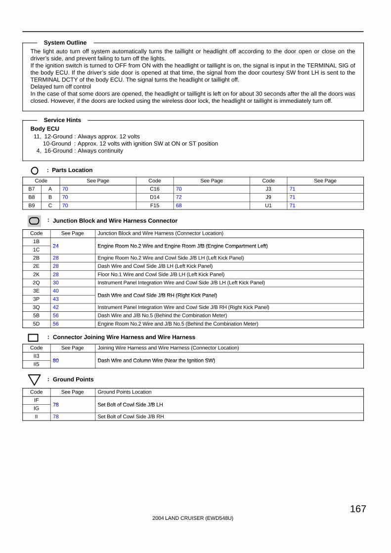
2004 LAND CRUISER (EWD548U)
167
The light auto turn off system automatically turns the taillight or headlight off according to the door open or close on thedriver’s side, and prevent failing to turn off the lights.If the ignition switch is turned to OFF from ON with the headlight or taillight is on, the signal is input in the TERMINAL SIG ofthe body ECU. If the driver’s side door is opened at that time, the signal from the door courtesy SW front LH is sent to theTERMINAL DCTY of the body ECU. The signal turns the headlight or taillight off.Delayed turn off controlIn the case of that some doors are opened, the headlight or taillight is left on for about 30 seconds after the all the doors wasclosed. However, if the doors are locked using the wireless door lock, the headlight or taillight is immediately turn off.
Body ECU11, 12-Ground : Always approx. 12 volts
10-Ground : Approx. 12 volts with ignition SW at ON or ST position4, 16-Ground : Always continuity
: Parts Location
Code See Page Code See Page Code See Page
B7 A 70 C16 70 J3 71
B8 B 70 D14 72 J9 71
B9 C 70 F15 68 U1 71
: Junction Block and Wire Harness Connector
Code See Page Junction Block and Wire Harness (Connector Location)
1B24 Engine Room No 2 Wire and Engine Room J/B (Engine Compartment Left)
1C24 Engine Room No.2 Wire and Engine Room J/B (Engine Compartment Left)
2B 28 Engine Room No.2 Wire and Cowl Side J/B LH (Left Kick Panel)
2E 28 Dash Wire and Cowl Side J/B LH (Left Kick Panel)
2K 28 Floor No.1 Wire and Cowl Side J/B LH (Left Kick Panel)
2Q 30 Instrument Panel Integration Wire and Cowl Side J/B LH (Left Kick Panel)
3E 40Dash Wire and Cowl Side J/B RH (Right Kick Panel)
3P 43Dash Wire and Cowl Side J/B RH (Right Kick Panel)
3Q 42 Instrument Panel Integration Wire and Cowl Side J/B RH (Right Kick Panel)
5B 56 Dash Wire and J/B No.5 (Behind the Combination Meter)
5D 56 Engine Room No.2 Wire and J/B No.5 (Behind the Combination Meter)
: Connector Joining Wire Harness and Wire Harness
Code See Page Joining Wire Harness and Wire Harness (Connector Location)
II380 Dash Wire and Column Wire (Near the Ignition SW)
II580 Dash Wire and Column Wire (Near the Ignition SW)
: Ground Points
Code See Page Ground Points Location
IF78 Set Bolt of Cowl Side J/B LH
IG78 Set Bolt of Cowl Side J/B LH
II 78 Set Bolt of Cowl Side J/B RH
System Outline
Service Hints
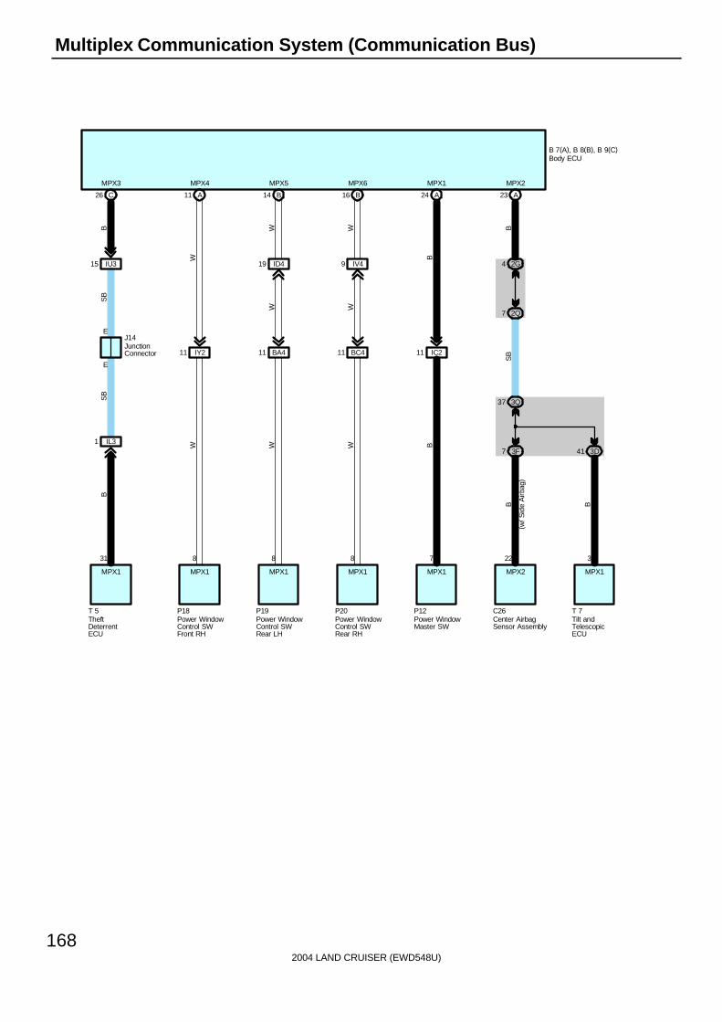
2004 LAND CRUISER (EWD548U)
168
Multiplex Communication System (Communication Bus)
IU315
IL31
E
E
C26
31
T 5
J14
A11
IY211
8
P18
B14
BA411
8
P19
B16
BC411
8
P20
A24
IC211
7
P12
A23
22
C26
3
T 7
ID419 IV49 2G4
2Q7
3F7
3Q37
3D41
B 7(A), B 8(B), B 9(C)
BS
B
W
SB
B
W W W B
B B
SB
B
B
WWW W
MPX3 MPX4 MPX5 MPX6 MPX1 MPX2
MPX1 MPX1 MPX1 MPX1 MPX1 MPX2 MPX1
(w/ S
ide
Airb
ag)
Center AirbagSensor Assembly
Power WindowMaster SW
Power WindowControl SWFront RH
Power WindowControl SWRear LH
Power WindowControl SWRear RH
TheftDeterrentECU
Tilt andTelescopicECU
Body ECU
JunctionConnector
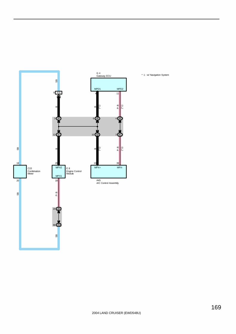
2004 LAND CRUISER (EWD548U)
169
19
20
C15
29
18
E 8
2E24
2Q66
3 4F
4C12
IU19
BP
-BSB
SB
BS
B
SB
6 4E
4A10
4 4E
4C3
19 39
A45
4 11B P-B
B
P-B
G 4
MPD1 MPD2
MPX1
MPX2 MPX+ MPX-
( *1)
( *1)
( *1)
( *1)
* 1 : w/ Navigation System
CombinationMeter
Engine ControlModule
Gateway ECU
A/C Control Assembly

2004 LAND CRUISER (EWD548U)
170
Multiplex Communication System (Communication Bus)
Multiplex Communication System Includes Following Systems
∗ Automatic Light Control
∗ Door Lock Control
∗ Front Fog Light
∗ Headlight
∗ Interior Light
∗ Key Reminder
∗ Light Auto Turn Off
∗ Power Window
∗ Theft Deterrent
∗ Wireless Door Lock Control

2004 LAND CRUISER (EWD548U)
171
Memo

2004 LAND CRUISER (EWD548U)
172
Multiplex Communication System
120AJ/BNO. 1
140AALT
F15
From Power Source System (See Page 94)
7. 5
AID
LE U
P
2G2
B 7(A), B 8(B), B 9(C)
A27 A3
Battery
1 5
2 3
2G1
2K9 2Q79
1
4
3
OF
F
DO
OR
ON
BR18
BR19BR111
F11
F10
G- W
B- G
SB
L- Y
B- G
R
R-W
L-Y
SB
R
RW
W-B
W W
W-B
DO
ME
Rel
ay
DEF LMRY
W- B
R
G-W
B 7 B 7
B 7
IF
2L11
W-B
2
1
1
R
2L825
A D
OO
R
12
BDR1
Fron
t P
erso
nal L
ight
Body ECU
Front Interior LightRear Personal Light
Fusible Link Block
B
120AMAIN
2
B- G
B- G

2004 LAND CRUISER (EWD548U)
173
BR15
BR14
2L18
2E12
6
2
2E15
2L3
3Q80
3K22
1
2
1
2
1
2
1
2
IY212 BC42 IC212 BA42
IV48 ID420
B22 B21A26A25
BC41 BA41
V 6
V 7
R27
D11
D13
D10
D12
T10
G- W
B- G
SB
L- Y
R
WG
-Y
G-W
R
R R R RG
-R
G-W
G-R
G-B
G-R
G-Y
G-Y
G-R
G-B
G-W
R
PCYL RCYL DCYL LCYL
B- G
SB
L- Y
G- Y
R R SB
RR
B 7(A), B 8(B), B 9(C)
ILE
13
2
1
2
1 1
OF
F
DO
OR
ON
W
2 3J7
B 7B 7
B 7
R R
R
W-B
W-B
W- B
R
G- Y
W- B
R
2Q272I42K222E22
Doo
r C
ourt
esy
Ligh
t Fro
nt L
H
Doo
r C
ourt
esy
Ligh
t Fro
nt R
H
Doo
r C
ourt
esy
Ligh
t Rea
r LH
Doo
r C
ourt
esy
Ligh
t Rea
r R
H
Rea
r In
terio
r Li
ght
Igni
tion
Key
Cyl
inde
r Li
ght
Van
ity L
ight
LH
Van
ity L
ight
RH
Body ECU
B- G B- G
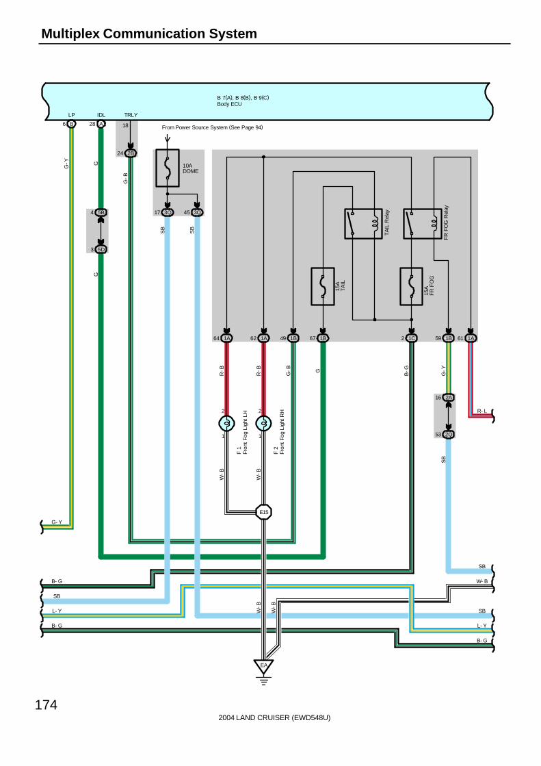
2004 LAND CRUISER (EWD548U)
174
Multiplex Communication System
B- G
SB
L- Y
B 7(A), B 8(B), B 9(C)
10ADOME
3Q17 3Q455B4
5D3
2B24
A28
2A16
2Q53
From Power Source System (See Page 94)
1C2 1B591B491A621A64
15A
FR F
OG
FR
FO
G R
elay
TA
IL R
elay
1B67
EA
R- L
SB
W- B
SB
L- Y
IDL TRLY
GG
G-B
SB
R-B
R-B
G-B G B-G
G-Y
SB
W-B
18
SB
1
2
F 2
W-B
15A
TAIL
1
2
F 1
W-B
E15
W-B
G-Y
LP
B6
G- Y
Fron
t Fog
Lig
ht L
H
Fron
t Fog
Lig
ht R
H
Body ECU
1A61
B- G
B- G

2004 LAND CRUISER (EWD548U)
175
B 7(A), B 8(B), B 9(C)
10AHEADLH- LWR
1A19 12 1A
20AHEADLH- UPR
10AHEADRH- LWR
1A9 1B22 1B10
2B7
2G9
1A26
1
2
1
2
1
2
24 1A
30 1A
A7
DRL
R- L
SB
W- B
SB
L- Y
W- B
R- W
SB
R- B
W- B
SB
L- Y
W-B
R-L
R-B
R-B
W-B
R-G
R-W
W-B
W-B
R-Y
R-Y
H 2
H 4
H 1
HE
AD
Rel
ay
HE
AD
HI R
elay
R- BE 1
W- B
E 2
20AHEADRH- UPR
1A8
R- W
R-W
Hea
dlig
ht L
H( H
igh)
Hea
dlig
ht L
H( L
ow)
Hea
dlig
ht R
H( L
ow)
Body ECU
1C1
B-G R-L
B- G
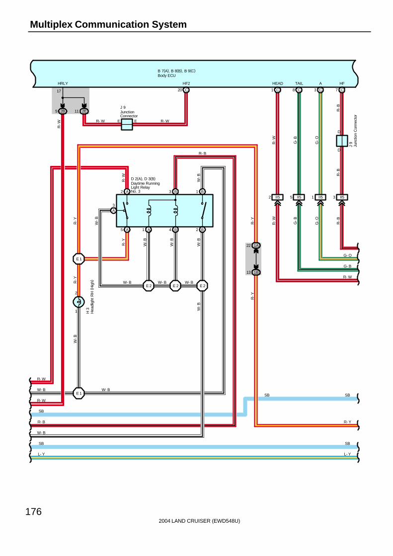
2004 LAND CRUISER (EWD548U)
176
Multiplex Communication System
B 7(A), B 8(B), B 9(C)
W- B
R- W
SB
R- B
W- B
SB
L- Y
2B5 2E11
17
HRLY
C20
A5 A1 B4 B2
1
2
B1
1B13
1A22
D 2(A), D 3(B)
J 9
E ER- W R- W
C1 C8 C3 C7
D
D
II53II51II52
J 9
H 3
II55
G- O
G- B
R- W
SB
R- Y
W-B
W-B
R-Y
W-B
W-B
W-B
R-Y
R-W G-B
G-O
R-B
R-B
R-B
G-O
G-B
R-W
R-Y
W-B
R-Y
W- B
W-B
HF2
W- B W- B
L- Y
SB
R-W
HEAD TAIL A HF
E 2 E 2 E 2
E 1 SB
A3
A2 B3
E 1
R-Y
R- W
R-W
W- B
Daytime RunningLight RelayNo. 3
Hea
dlig
ht R
H (
Hig
h)
Body ECU
Junc
tion
Con
nect
or
JunctionConnector
R- B
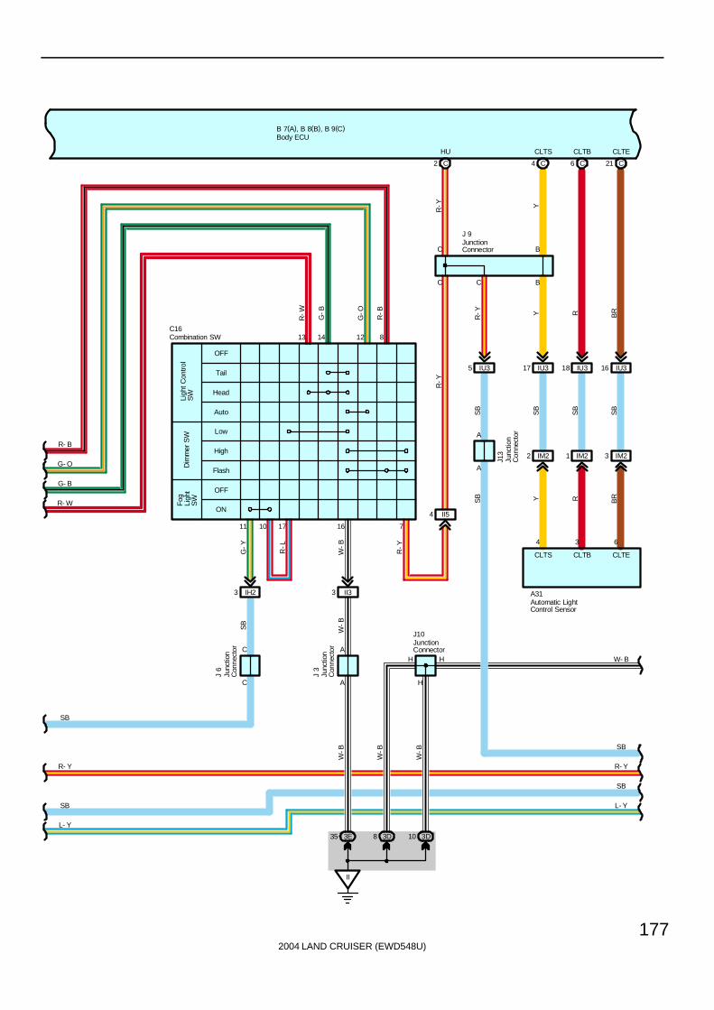
2004 LAND CRUISER (EWD548U)
177
B 7(A), B 8(B), B 9(C)
Auto
Low
High
Flash
OFF
ON
Dim
mer
SW
Fog
Ligh
tS
W
Ligh
t Con
trol
SW
OFF
Tail
Head
SB
G- O
R- Y
R- B
R- W
L- Y
SB
II54
II33
IU35 IU317 IU318 IU316
A
A
C
C
C2 C6 C21C4
CLTS CLTB CLTE
4 3 6
11 10 17 16
13 14 12 8
J 9
A31
J13
A
A
II
3E35 3D8 3D10
H
H H
7
J 3
J10
C16
B
C B
G-Y
R-L
W-B
R-Y
SB Y R BR
SB
SB
SB
SB
R-Y
R-Y
Y R BR
R-W
G-B
G-O
R-B
R-Y Y
W-B
W-B
W-B
HU CLTS CLTB CLTE
W- B
SB
R- Y
SB
L- Y
G- B
SB
W-B
Automatic LightControl Sensor
Combination SW
Body ECU
JunctionConnector
JunctionConnector
Junc
tion
Con
nect
or
Junc
tion
Con
nect
or
C
C
Junc
tion
Con
nect
or
J 6
IM23IM21IM22
IH23

2004 LAND CRUISER (EWD548U)
178
Multiplex Communication System
B 7(A), B 8(B), B 9(C)
W- B
SB
R- Y
SB
L- Y
10AHORN
1B21
2B9
2Q24
C
C
T 5
2Q26
2Q22 2I2
IL312 IL322 IL36
10AECU- B2
From Power Source System(See Page 94)
3Q44 3Q71
IF
2Q20
2E
18
LP(*1)
B14 (*2)A21 (*1)
A3 (*1)
B8 (*2)
3Q76
3D12
IL35 IL320
3Q73
3E13
4D14
4D5
J14
M 5
( A) ,
M 9
( B)
3E20
3E12
7B7
7B8
9
7
HO
RN
Rel
ay
C17
D 7
OBD2
+B2 E HORN IND REV
3 29 5 25 23
SB
G-O
SB
SB
B
W-B
G-O
G-R B
SB
V-W
V-W
V-W
SB
L-W
SB
SB
SB
B
G-R
SB
W-B
B
V- W
L- W
SB
TAC
SIL
L- Y
SB
R- Y
SB
W- B W- B
SB
SB
11
BECU
SECURITY(*2)
GND(*2)GND1(*1)GND1(*1)
Dat
a Li
nkC
onne
ctor
3
Mul
ti-D
ispl
ay
Theft Deterrent ECU
Body ECU
Junc
tion
Con
nect
or

2004 LAND CRUISER (EWD548U)
179
B 7(A), B 8(B), B 9(C)
IL38
3Q82
3B4
EA26
2
1
EA
IL37
6 3B
84 3Q
1
E 3
T 1
IL33
IU314
7. 5ASECURITY
From Power Source System(See Page 94)
3E163Q72
IL314
Z 1
SB
L- Y
SB
R- Y
SB
L- Y
SB
R- Y
W- B
SB
L- W
34 1 11 2
DSWH SH- GBS +B1
L-B
W Y-G LG
SB
SB
SB
SB
LG
SB
L-B
W
Y-G
L-B
W-B
T 5
LG
2
1
SB
L- W
SB
W- B
* 1 : w/ Navigation System* 2 : w/o Navigation System
Eng
ine
Hoo
dC
ourt
esy
SW
The
ft D
eter
rent
Hor
n
Theft Deterrent ECU
Body ECU
10
IG
IL315
B
12 31
R-B
MPX1
SB
KSW
IL39 IL31
E
E
IU315
C26
SB
SB
B
MPX3
J14
Junc
tion
Con
nect
or
B-W
SB
Opt
ion
Con
nect
or( G
lass
Bre
akag
e S
enso
r)

2004 LAND CRUISER (EWD548U)
180
Multiplex Communication System
B 7(A), B 8(B), B 9(C)
SB
L- W
SB
W- B
SB
L- Y
SB
R- Y
18 3E
46 3Q
23 3E
C14
KSW
R-B
1
2
1 3P
3 3P
U 1
R-B
W-B
W-B
1 6 3 4 5
DN UP LMT PLS SGND
EPLSLMTUP
1 4 2 3 5
G Y L-Y
L-W
BR
-B
WW
P15
A11
IY211
MPX4
20AP/W(FR)
From Power Source System (See Page 94)
3I2
8
MPX1
12
BDR
11
PCT
Y- B
L- W
B- W
SB
SB
L- Y
R- Y
SB
W- B
GND
7W
-B
SEL1
9
W-B
W-B
P18
SB
L
Y-B
B 8
B 8
3I9
II
W-B
Power Window Motor Front RH
Power WindowControl SWFront RH
Unl
ock
War
ning
SW
Body ECU
10
SIG
10AECU- IG1
2Q21 1 2I
L
B-WSB
74 3Q
SB
SB
SB
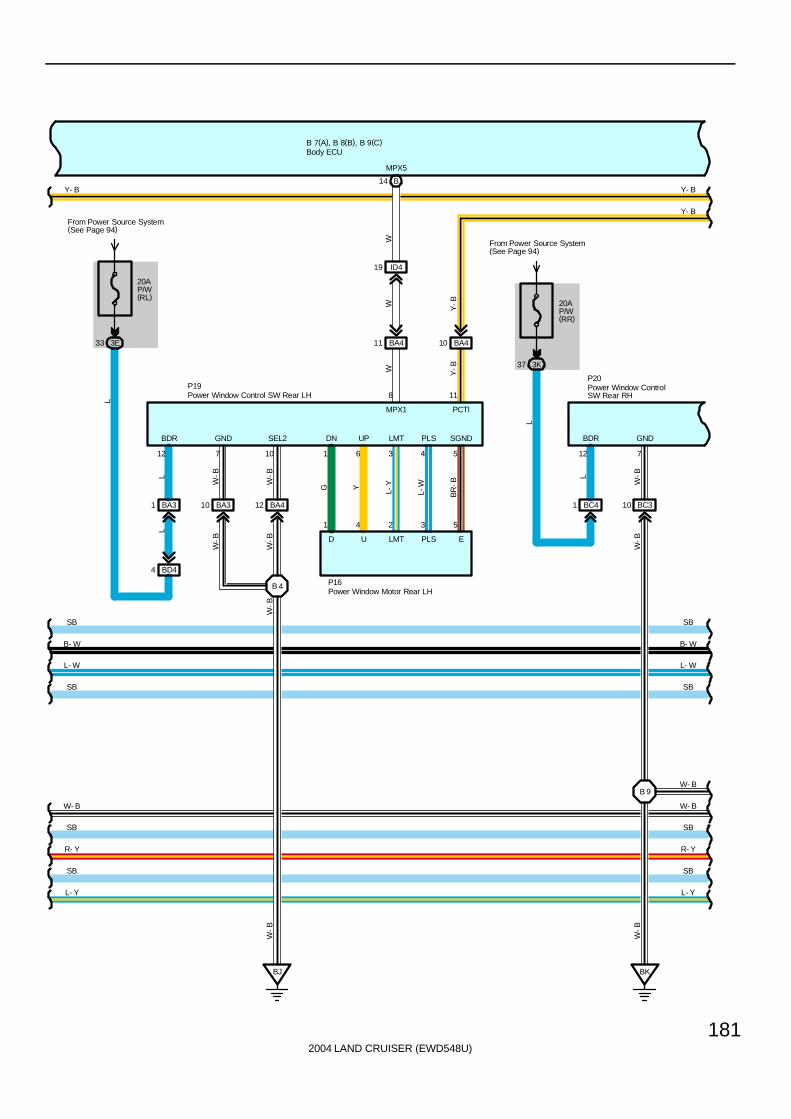
2004 LAND CRUISER (EWD548U)
181
B 7(A), B 8(B), B 9(C)
W
Y-B
1 6 3 4 5
DN UP LMT PLS SGND
EPLSLMTUD
1 4 2 3 5
G Y L-Y
L-W
BR
-BY
-BWW
P16
B14
ID419
BA411 BA410
MPX5
20AP/W(RR)
From Power Source System(See Page 94)
3K37
BC41 BC310
BK
12 7
BDR GND
L
W-B
W-B
L
Y- B
Y- B
BA310 BA412
BJ
7 10
GND SEL2
W-B
W-B
W-B
BA31
BD44
20AP/W(RL)
From Power Source System(See Page 94)
3E33
L
12
BDR
LL
W-B
W-B
W-B
W-B
11
PCTI
8
MPX1
Y- B
L- W
B- W
SB
L- W
B- W
SB
SB
L- Y
R- Y
SB
W- B
W- B
SB
L- Y
R- Y
SB
W- B
P19P20
SBSB
B 4
B 9
Power Window Motor Rear LH
Power Window Control SW Rear LHPower Window ControlSW Rear RH
Body ECU

2004 LAND CRUISER (EWD548U)
182
Multiplex Communication System
B 7(A), B 8(B), B 9(C)
L- W
B- W
SB
L- Y
R- Y
SB
W- B
1 6 3 4 5
DN UP LMT PLS SGND
EPLSLMTUD
1 4 2 3 5
G Y L-Y
L-W
BR
-B
P17
B16
IV49
BC411 BC410
MPX6
SB
WW Y-B
Y-B
W
2J10
2K262Q743Q193J43K30
6
SBY- B
Y-B
Y-B
Y-B
SB
20AP/W(FL)
From Power Source System(See Page 94)
3E1
7 2I
42 2E
Y- B
Y- B
WLSW
P12P20
L
L
B-W
L-W
10 20 9
BDR SIG CPUB
11 1 5 15 13
DN UP LMT PLS SGND
EPLSLMTUD
1 4 2 3 5G Y L-
Y
L-W
BR
-B
P14
W- B
SB
L- Y
R- Y
SB
W- B
SB
W- B
SB
8 11
PCTIMPX1
Power Window Master SW
Power Window Motor Front LHPower Window Motor Rear RH
Power Window ControlSW Rear RH
Body ECU
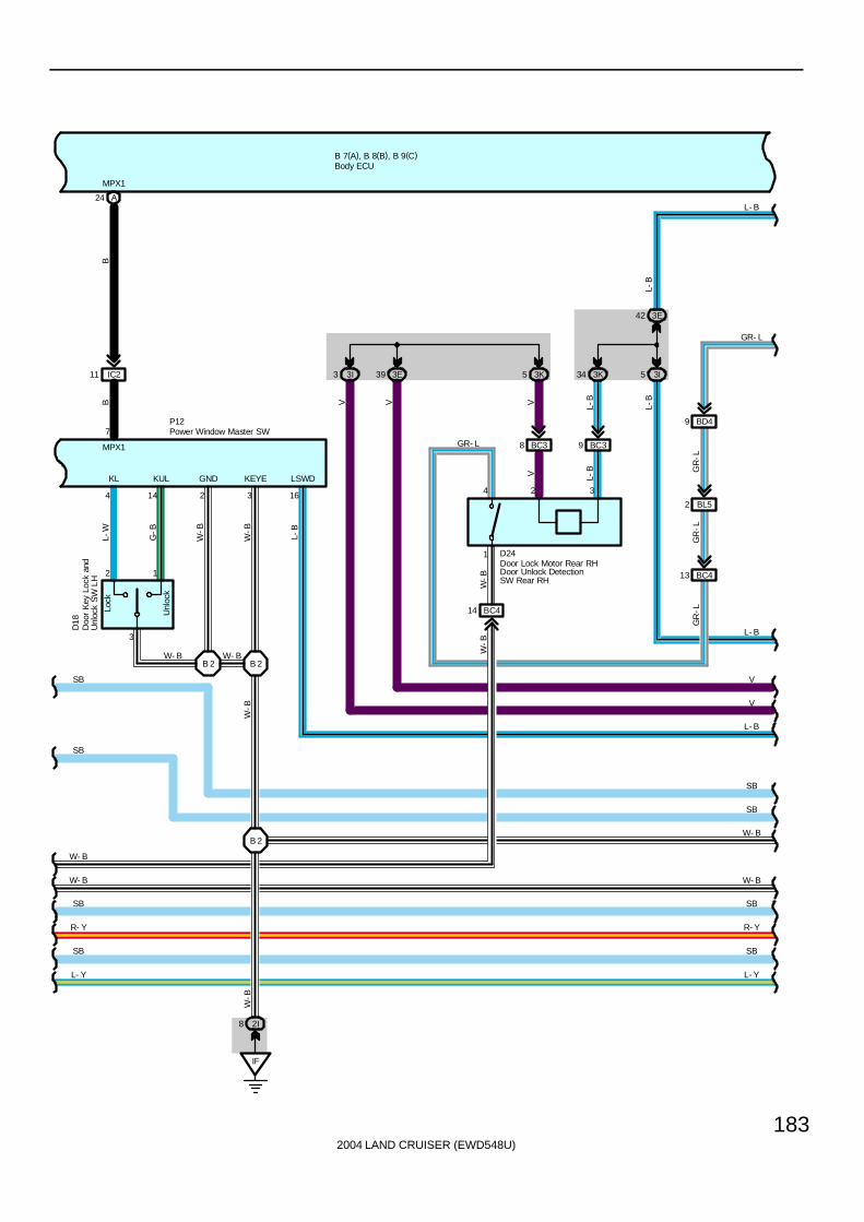
2004 LAND CRUISER (EWD548U)
183
B 7(A), B 8(B), B 9(C)
24 A
IC211
7
MPX1
BB
MPX1
Unl
ock
Lock
3
2 1
D18
4 14 2 3 16
KL KUL GND KEYE LSWD
L-W
G-B
W-B
W-B
L-B
W- BW- B
P12
W- B
SB
W- B
SB
R- Y
L- Y
SB SB
L- Y
R- Y
SB
W- B
SB
W-B
W- B
L- B
BC414
BC38 BC39
3K5 3K34 3I5
3E42
3I3 3E39
BC413
BL52
BD49
4 2 3
1
V L-B
V L-B
W-B
W-B
V V L-B
GR
-LG
R-L
GR- L
D24
GR- L
L- B
V
V
SB
SB
L- B
L-B
GR
-L
B 2 B 2
B 2
IF
2I8
W-B
Doo
r K
ey L
ock
and
Unl
ock
SW
LH
Door Lock Motor Rear RHDoor Unlock DetectionSW Rear RH
Power Window Master SW
Body ECU
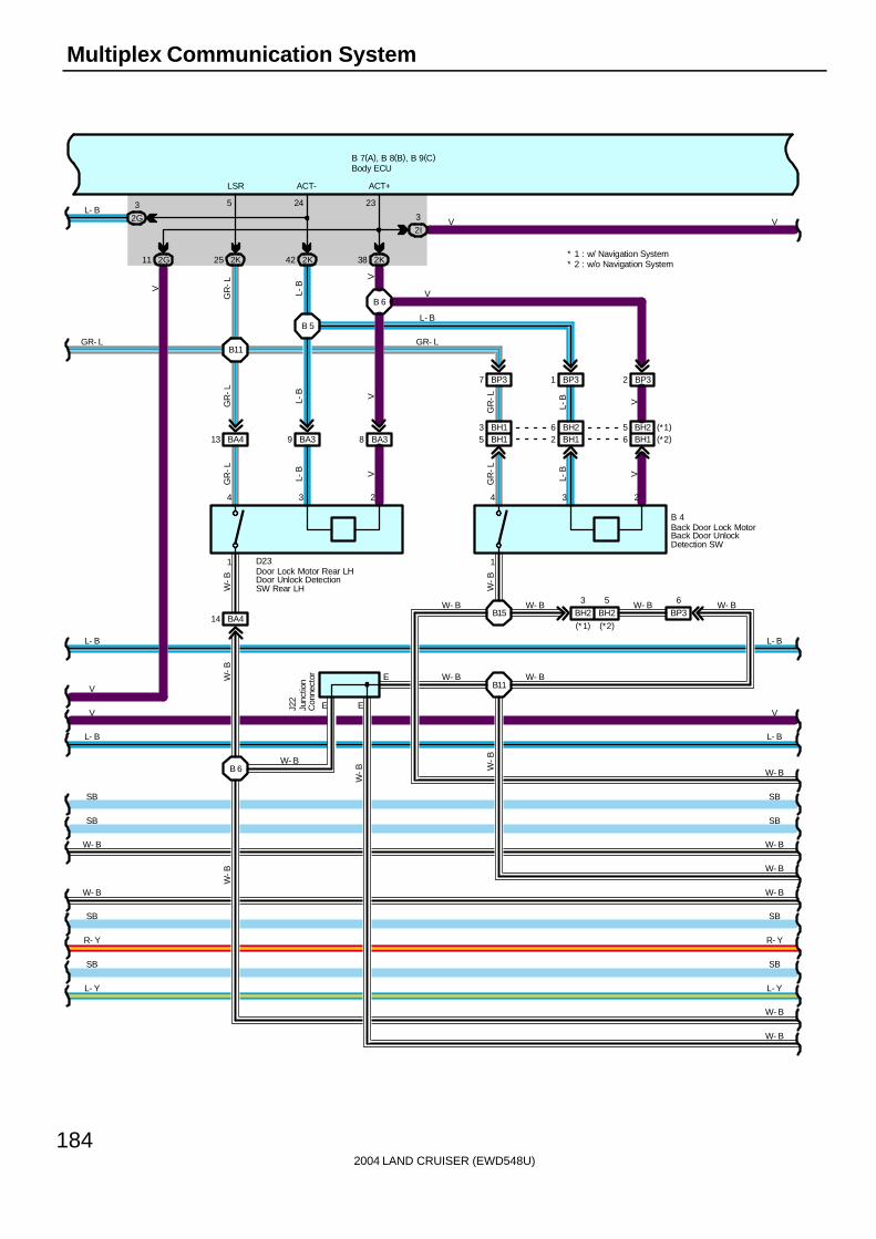
2004 LAND CRUISER (EWD548U)
184
Multiplex Communication System
B 7(A), B 8(B), B 9(C)
2G11
BA39 BA38
4 3 2
1
L-B V
W-B
4 3 2
1L-
B V
W-B
BA413
2K25 2K42 2K38
BP37 BP31 BP32
GR
-L
L-B V
GR
-L
L-B V
GR
-L
GR
-L
V
L-B
GR
-LV
V
L- B
GR- L
W- B
W- B
SB
R- Y
L- Y
SB
L- B
GR- L
L- B
V
V
SB
SB
2G
3L- B
BH25
BP36
LSR ACT- ACT+
5 24 23
E
EJ22
W- B
W- B
SB
R- Y
L- Y
SB
L- B
L- B
V
SB
SB
W- B
W-B
W- B W- B W- B
W- BW-B
W- B
W- B
BA414
W-B
B 4
B15
B11
B 6
B11
B 5
B 6
2I
3 V
D23
W- B
W- B
V
Back Door Lock MotorBack Door UnlockDetection SW
Door Lock Motor Rear LHDoor Unlock DetectionSW Rear LH
Body ECU
Junc
tion
Con
nect
or
W- B
E
W-B
BH12 BH16BH15
W- B
BH23
(*1) (*2)
BH13 BH26 BH25 (*1)(*2)
* 2 : w/o Navigation System* 1 : w/ Navigation System
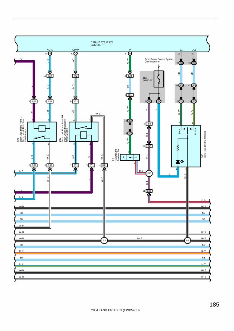
2004 LAND CRUISER (EWD548U)
185
B 7(A), B 8(B), B 9(C)
BS18 BS14 BT12 BT13 BT14
BS13 BS12 BT18
IY24IC213
A10 A30
Unl
ock
Lock
3 1
3Q35
3I7 3J13
2Q9 2Q10
3Q41
10AGAUGE2
From Power Source System(See Page 94)
3I1
ACTD LSWP
4 1 3 2
4
432
D21
D22
W- B
W- B
SB
R- Y
L- Y
SB
L- B
L- B
V
SB
SB
W- B
W- B
19 15
L1 UL1
W- B
V L-B
L-O
L-B
L-O
V L-B
L-O
L
G-W
G-O
SB
SB
V
W-B W
-B
W-B
L-B
L-B V
W-B
W-B
L
W- B
2
W- B
SB
R- Y
L- Y
SB
SB
SB
W- B
W- B
W- B
B 8 B 8
V
D20
3E3
R- L
R-L
Doo
r Lo
ck C
ontr
ol S
W R
H
Doo
r Lo
ck M
otor
Fro
nt L
HD
oor
Unl
ock
Det
ectio
nS
W F
ront
LH
Doo
r Lo
ck M
otor
Fro
nt R
HD
oor
Unl
ock
Det
ectio
nS
W F
ront
RH
Body ECU
W- B W- B
EB111
Ib26
IN214R
-LR
-L
E10
R-LP
1
3
6D13
6D12
IX11
IU32
B17
G-W
SB
G-W
G-W
P
R- L
Par
k/N
eutr
alP
ositi
on S
W
P 1
1
W- B

2004 LAND CRUISER (EWD548U)
186
Multiplex Communication System
B 7(A), B 8(B), B 9(C)
Lock
Unl
ock
3
1 2
Lock
Unl
ock
1
3 2
BQ22 BQ210 BP41 BP49
24 2K
12 2Q
14 3J
40 3E
42 3Q
3I8 3Q30
2K292Q11
A22
BP48 BP43
ID417 ID418
B4 B3
1 1
10 2K
8 2E
26 3K
15 3E
B23 B24
D14
D15
D27
D19
B 3
W- B
SB
R- Y
L- Y
SB
SB
SB
W- B
W- B
W- B
SB
R- Y
SB
SB
SB
W- B
G-B
SB
G-B
L-W
G-B
W-B
G-B
W-B
L-Y
W-B
L V
R-Y
R-B
L V
L V
R-Y
R-B
G-B
W-B
L-Y
W-B
L-W
SB
G- B
UL2 L2 RDA PRG DCTY
20
5 1
2 3
BQ21
L-W
PCTY
B11
BJ
W- B
W-B
R- L
R- L
Bac
k D
oor
Key
Loc
kan
d U
nloc
k S
W
Doo
r C
ourt
esy
SW
Fron
t LH
Doo
r C
ourt
esy
SW
Fron
t R
H
Doo
r K
ey L
ock
and
Unl
ock
SW
RH
Body ECU
Doo
r C
ontr
ol R
ecei
ver
+B E
RDA PRG
W- B W- B

2004 LAND CRUISER (EWD548U)
187
B 7(A), B 8(B), B 9(C)
1 1
1
2
B11 B12
ID415 IV37
ID416
B7
C
C
BP411
BH24
D16
D17
J22
B 2
SB
R- Y
SB
SB
SB
W- B
IG16
IU44
7. 5AACC
From Power Source System (See Page 94)
2Q57
7. 5AMET
3Q7
R-L
R-G
R-L
R-G
R-L
R-L
R-L
R-L
R-L
R-Y
SB
R-Y
W-B
SB
SB
SB
SB
SB
SB
SB
SB
SB
SB
RLCY RRCY BCTY
R- L R- L
10AGAUGE1
2Q65
SB
A
AJ14
SB
Bac
k D
oor
Cou
rtes
y S
W
Doo
r C
ourt
esy
SW
Rea
r LH
Doo
r C
ourt
esy
SW
Rea
r R
H
Body ECU
Junc
tion
Con
nect
or
JunctionConnector
ACC
22
W- B W- B
BH15 (*1)(*2)
* 2 : w/o Navigation System* 1 : w/ Navigation System

2004 LAND CRUISER (EWD548U)
188
Multiplex Communication System
B 7(A), B 8(B), B 9(C)
Doo
r
Bea
m
C12
( A) ,
C13
( B) ,
C14
( C) ,
C15
( D)
D11 D12 D13 D14A7 A10
D9 D10 A3A5 B8
9 3Q
19 3E
C12
IU33
C11
SB
SB
SB
SB
SB
SB
SB
7. 5APANEL
From Power Source System(See Page 94)
1B6383 2Q
11 2B
SB
SB
SB
SB
SB
SB
SB
G
G-Y
R-Y
DCY2 DRLP
SB
SB
IX16
EB110
D15
1
3
2
SB
R-G
R- G
BRR- L
Buz
zer
Com
bina
tion
Met
er
Body ECU
Vehicle Speed Sensor(Combination Meter)
V 2
W- B W- B
SB
SB
Spe
edom
eter
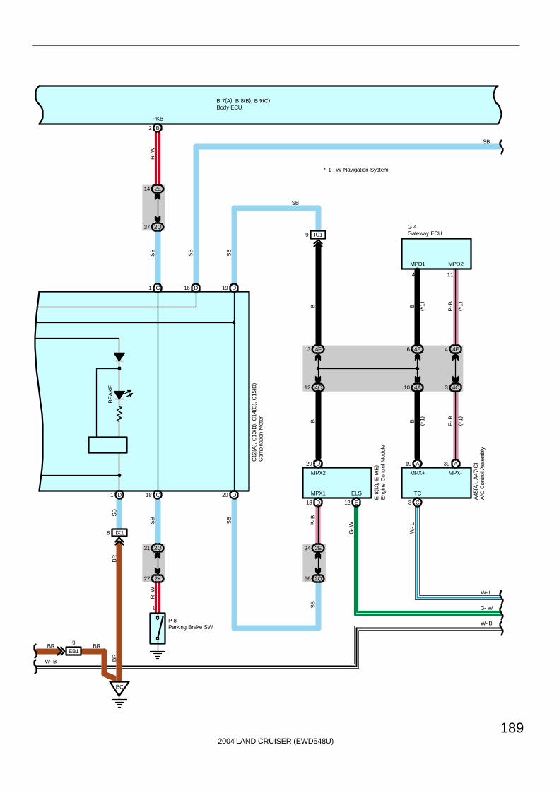
2004 LAND CRUISER (EWD548U)
189
B 7(A), B 8(B), B 9(C)
BE
AK
E
C18 D20D1
C1 D16 D19
37 2Q
14 2E
IX18
EC
B2
27 2K
31 2Q
1
IU19
12 4C
3 4F
10 4A
6 4E
3 4C
4 4E
C3
A19 A39
D18 E12
66 2Q
24 2E
E 8
( D) ,
E 9
( E)
MPX2 MPX+ MPX-
4 11
MPX1 ELS TC
R-W
B B P-B
P-BBB
P-B
G-W
W-L
SB
SB
SB
SB
SB
R-W
SB
W- L
G- W
PKB
G 4
C12
( A) ,
C13
( B) ,
C14
( C) ,
C15
( D)
SB
SB
( *1)
( *1)
* 1 : w/ Navigation System
( *1)
( *1)
D29
SB
MPD1 MPD2
P 8
A45
( A) ,
A47
( C)
BR
BR
BR
Com
bina
tion
Met
er
Eng
ine
Con
trol
Mod
ule
Gateway ECU
Parking Brake SW
A/C
Con
trol A
ssem
bly
Body ECU
W- B
W- B
EB1
9 BR

2004 LAND CRUISER (EWD548U)
190
Multiplex Communication System
B 7(A), B 8(B), B 9(C)
B
2Q70
B
A13
18 2K
10 2G
BU13
BM25
2
BM24
BU11
SB
W- L
G- W
3E21
3E26 3D13
4A8
4A17
C5
Mul
ti-D
ispl
ay
A15
10 5C
1 5B
J14
IU34
IF14
C18
5
TC
R 6
BG
G-W
G-W G
GG
W-B
W-B
W-B
BS
B
TCDBKLELS1SPD
14
SB
SB
W-L
W-L
W-L
W-L
ACAN
Rheostat
Body ECU
Junction ConnectorC
ente
r A
irbag
Sen
sor
Ass
embl
y
31
Buc
kle
SW
LH
B 5
G
W-L
Rad
io a
nd P
laye
r
6 4B
W- B
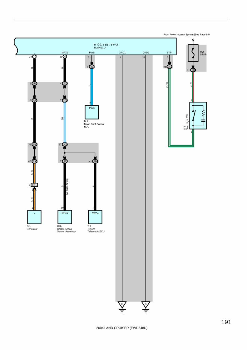
2004 LAND CRUISER (EWD548U)
191
B 7(A), B 8(B), B 9(C)
2G8
2B6
14 A
2G4
2Q7
23 A
3Q37
3F7 3D41
22
MPX2
C26
3
MPX1
T 7
1B38
1A40
4
L
G 1
2L9
2
PWS
M 2
IF IG
B-O
B B
B SB
B B
4 16
L MPX2 PWS GND1 GND2
L
21
( w/ S
ide
Airb
ag)
Center AirbagSensor Assembly
Generator
Moon Roof ControlECU
Tilt andTelescopic ECU
Body ECU
3
G-W
2D35
STPI
B-O
EE12
15ASTOP
From Power Source System (See Page 94)
2D31
1
2
G-R
Sto
p Li
ght
SW
S 5
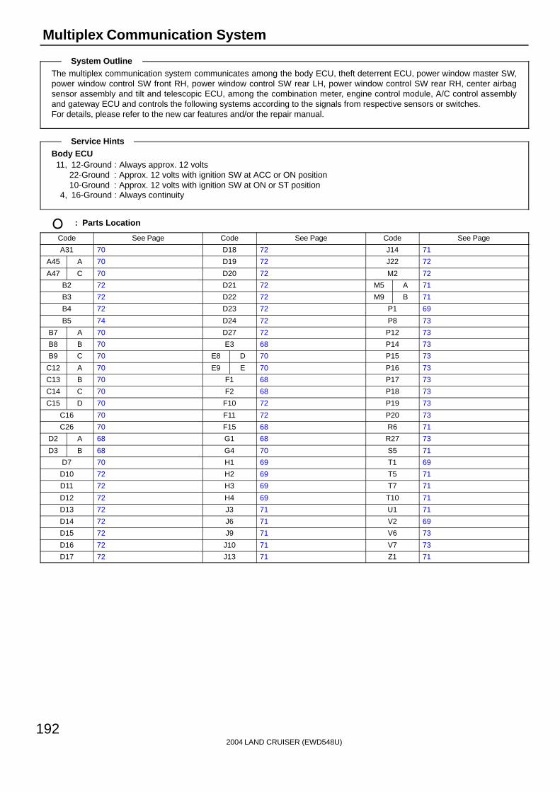
2004 LAND CRUISER (EWD548U)
192
Multiplex Communication System
The multiplex communication system communicates among the body ECU, theft deterrent ECU, power window master SW,power window control SW front RH, power window control SW rear LH, power window control SW rear RH, center airbagsensor assembly and tilt and telescopic ECU, among the combination meter, engine control module, A/C control assemblyand gateway ECU and controls the following systems according to the signals from respective sensors or switches.For details, please refer to the new car features and/or the repair manual.
Body ECU11, 12-Ground : Always approx. 12 volts
22-Ground : Approx. 12 volts with ignition SW at ACC or ON position10-Ground : Approx. 12 volts with ignition SW at ON or ST position
4, 16-Ground : Always continuity
: Parts Location
Code See Page Code See Page Code See Page
A31 70 D18 72 J14 71
A45 A 70 D19 72 J22 72
A47 C 70 D20 72 M2 72
B2 72 D21 72 M5 A 71
B3 72 D22 72 M9 B 71
B4 72 D23 72 P1 69
B5 74 D24 72 P8 73
B7 A 70 D27 72 P12 73
B8 B 70 E3 68 P14 73
B9 C 70 E8 D 70 P15 73
C12 A 70 E9 E 70 P16 73
C13 B 70 F1 68 P17 73
C14 C 70 F2 68 P18 73
C15 D 70 F10 72 P19 73
C16 70 F11 72 P20 73
C26 70 F15 68 R6 71
D2 A 68 G1 68 R27 73
D3 B 68 G4 70 S5 71
D7 70 H1 69 T1 69
D10 72 H2 69 T5 71
D11 72 H3 69 T7 71
D12 72 H4 69 T10 71
D13 72 J3 71 U1 71
D14 72 J6 71 V2 69
D15 72 J9 71 V6 73
D16 72 J10 71 V7 73
D17 72 J13 71 Z1 71
System Outline
Service Hints

2004 LAND CRUISER (EWD548U)
193
: Junction Block and Wire Harness Connector
Code See Page Junction Block and Wire Harness (Connector Location)
1A 24 Engine Room Main Wire and Engine Room J/B (Engine Compartment Left)
1B24 Engine Room No 2 Wire and Engine Room J/B (Engine Compartment Left)
1C24 Engine Room No.2 Wire and Engine Room J/B (Engine Compartment Left)
2A28 Engine Room No 2 Wire and Cowl Side J/B LH (Left Kick Panel)
2B28 Engine Room No.2 Wire and Cowl Side J/B LH (Left Kick Panel)
2D
2E 28 Dash Wire and Cowl Side J/B LH (Left Kick Panel)
2G
( )
2I28 Front Door LH Wire and Cowl Side J/B LH (Left Kick Panel)
2J28 Front Door LH Wire and Cowl Side J/B LH (Left Kick Panel)
2K 28 Floor No.1 Wire and Cowl Side J/B LH (Left Kick Panel)
2L 28 Roof No.1 Wire and Cowl Side J/B LH (Left Kick Panel)
2Q 30 Instrument Panel Integration Wire and Cowl Side J/B LH (Left Kick Panel)
3B 40 Engine Room No.2 Wire and Cowl Side J/B RH (Right Kick Panel)
3D
3E 40 Dash Wire and Cowl Side J/B RH (Right Kick Panel)
3F
( g )
3I40 Front Door RH Wire and Cowl Side J/B RH (Right Kick Panel)
3J40 Front Door RH Wire and Cowl Side J/B RH (Right Kick Panel)
3K 40 Floor No.2 Wire and Cowl Side J/B RH (Right Kick Panel)
3P 43 Dash Wire and Cowl Side J/B RH (Right Kick Panel)
3Q 42 Instrument Panel Integration Wire and Cowl Side J/B RH (Right Kick Panel)
4A
4B
4C52 Dash Wire and J/B No 4 (Instrument Panel Center)
4D52 Dash Wire and J/B No.4 (Instrument Panel Center)
4E
4F
5B56 Dash Wire and J/B No 5 (Behind the Combination Meter)
5C56 Dash Wire and J/B No.5 (Behind the Combination Meter)
5D 56 Engine Room No.2 Wire and J/B No.5 (Behind the Combination Meter)
6D 60 Engine Wire and J/B No.6 (Behind the Grove Box)
7B 64 Dash Wire and J/B No.7 (Behind the Grove Box)
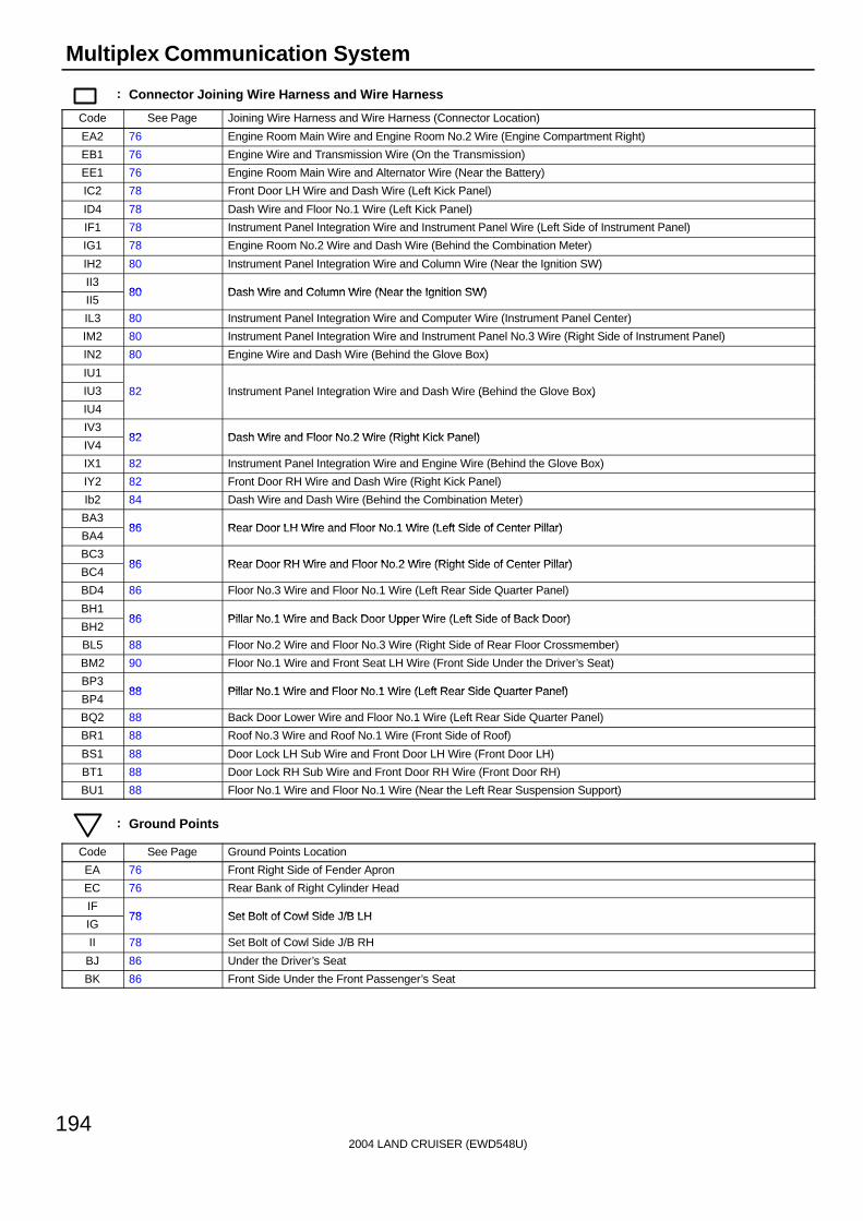
2004 LAND CRUISER (EWD548U)
194
Multiplex Communication System
: Connector Joining Wire Harness and Wire Harness
Code See Page Joining Wire Harness and Wire Harness (Connector Location)
EA2 76 Engine Room Main Wire and Engine Room No.2 Wire (Engine Compartment Right)
EB1 76 Engine Wire and Transmission Wire (On the Transmission)
EE1 76 Engine Room Main Wire and Alternator Wire (Near the Battery)
IC2 78 Front Door LH Wire and Dash Wire (Left Kick Panel)
ID4 78 Dash Wire and Floor No.1 Wire (Left Kick Panel)
IF1 78 Instrument Panel Integration Wire and Instrument Panel Wire (Left Side of Instrument Panel)
IG1 78 Engine Room No.2 Wire and Dash Wire (Behind the Combination Meter)
IH2 80 Instrument Panel Integration Wire and Column Wire (Near the Ignition SW)
II380 Dash Wire and Column Wire (Near the Ignition SW)
II580 Dash Wire and Column Wire (Near the Ignition SW)
IL3 80 Instrument Panel Integration Wire and Computer Wire (Instrument Panel Center)
IM2 80 Instrument Panel Integration Wire and Instrument Panel No.3 Wire (Right Side of Instrument Panel)
IN2 80 Engine Wire and Dash Wire (Behind the Glove Box)
IU1
IU3 82 Instrument Panel Integration Wire and Dash Wire (Behind the Glove Box)
IU4
g ( )
IV382 Dash Wire and Floor No 2 Wire (Right Kick Panel)
IV482 Dash Wire and Floor No.2 Wire (Right Kick Panel)
IX1 82 Instrument Panel Integration Wire and Engine Wire (Behind the Glove Box)
IY2 82 Front Door RH Wire and Dash Wire (Right Kick Panel)
Ib2 84 Dash Wire and Dash Wire (Behind the Combination Meter)
BA386 Rear Door LH Wire and Floor No 1 Wire (Left Side of Center Pillar)
BA486 Rear Door LH Wire and Floor No.1 Wire (Left Side of Center Pillar)
BC386 Rear Door RH Wire and Floor No 2 Wire (Right Side of Center Pillar)
BC486 Rear Door RH Wire and Floor No.2 Wire (Right Side of Center Pillar)
BD4 86 Floor No.3 Wire and Floor No.1 Wire (Left Rear Side Quarter Panel)
BH186 Pillar No 1 Wire and Back Door Upper Wire (Left Side of Back Door)
BH286 Pillar No.1 Wire and Back Door Upper Wire (Left Side of Back Door)
BL5 88 Floor No.2 Wire and Floor No.3 Wire (Right Side of Rear Floor Crossmember)
BM2 90 Floor No.1 Wire and Front Seat LH Wire (Front Side Under the Driver’s Seat)
BP388 Pillar No 1 Wire and Floor No 1 Wire (Left Rear Side Quarter Panel)
BP488 Pillar No.1 Wire and Floor No.1 Wire (Left Rear Side Quarter Panel)
BQ2 88 Back Door Lower Wire and Floor No.1 Wire (Left Rear Side Quarter Panel)
BR1 88 Roof No.3 Wire and Roof No.1 Wire (Front Side of Roof)
BS1 88 Door Lock LH Sub Wire and Front Door LH Wire (Front Door LH)
BT1 88 Door Lock RH Sub Wire and Front Door RH Wire (Front Door RH)
BU1 88 Floor No.1 Wire and Floor No.1 Wire (Near the Left Rear Suspension Support)
: Ground Points
Code See Page Ground Points Location
EA 76 Front Right Side of Fender Apron
EC 76 Rear Bank of Right Cylinder Head
IF78 Set Bolt of Cowl Side J/B LH
IG78 Set Bolt of Cowl Side J/B LH
II 78 Set Bolt of Cowl Side J/B RH
BJ 86 Under the Driver’s Seat
BK 86 Front Side Under the Front Passenger’s Seat
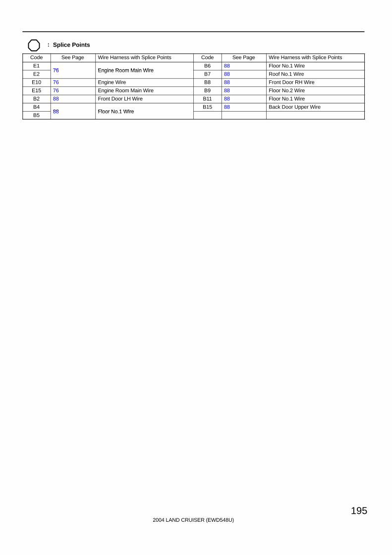
2004 LAND CRUISER (EWD548U)
195
: Splice Points
Code See Page Wire Harness with Splice Points Code See Page Wire Harness with Splice Points
E176 Engine Room Main Wire
B6 88 Floor No.1 Wire
E276 Engine Room Main Wire
B7 88 Roof No.1 Wire
E10 76 Engine Wire B8 88 Front Door RH Wire
E15 76 Engine Room Main Wire B9 88 Floor No.2 Wire
B2 88 Front Door LH Wire B11 88 Floor No.1 Wire
B488 Floor No 1 Wire
B15 88 Back Door Upper Wire
B588 Floor No.1 Wire

2004 LAND CRUISER (EWD548U)
196
Front Wiper and Washer
25AWIPER
From Power Source System (See Page 94)
3A7
Front Wiper SW Front Washer SW
EWWF
ON
OFF
B1+S INT2INT1
HI
+1+2+B
LO
INT
OFF
17 8 7 16 11 2
+B +2 +1 +S WF EW
II33II335II334II332II333
M
II
3E35
A
A
J 33G83G43G12
3A13 3A10 3A15
4 1 2 3
+2 +1 B S
5E
EB
W-B
W-B
W-B
W-B
L-Y
L-W
L-B
L-RL
L-W
L-B
L-RL
3G11
2D38
2A1
1A56
1B68
3
2
EA22
15AWASHER
3A9
L-Y
L-W
L-B
L-R
LL
L-Y
L-Y
LL
L
W 1
F 5
C19Combination SW
Front Wiper Motor
Was
her
Mot
or
JunctionConnector
II331
L-Y
M
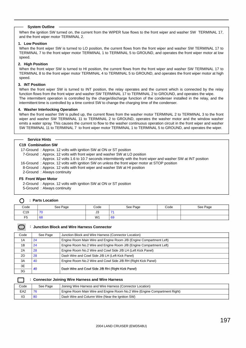
2004 LAND CRUISER (EWD548U)
197
When the ignition SW turned on, the current from the WIPER fuse flows to the front wiper and washer SW TERMINAL 17,and the front wiper motor TERMINAL 2.
1. Low PositionWhen the front wiper SW is turned to LO position, the current flows from the front wiper and washer SW TERMINAL 17 toTERMINAL 7 to the front wiper motor TERMINAL 1 to TERMINAL 5 to GROUND, and operates the front wiper motor at lowspeed.
2. High PositionWhen the front wiper SW is turned to HI position, the current flows from the front wiper and washer SW TERMINAL 17 toTERMINAL 8 to the front wiper motor TERMINAL 4 to TERMINAL 5 to GROUND, and operates the front wiper motor at highspeed.
3. INT PositionWhen the front wiper SW is turned to INT position, the relay operates and the current which is connected by the relayfunction flows from the front wiper and washer SW TERMINAL 17 to TERMINAL 2 to GROUND, and operates the wipe.The intermittent operation is controlled by the charge/discharge function of the condenser installed in the relay, and theintermittent time is controlled by a time control SW to change the charging time of the condenser.
4. Washer Interlocking OperationWhen the front washer SW is pulled up, the current flows from the washer motor TERMINAL 2 to TERMINAL 3 to the frontwiper and washer SW TERMINAL 11 to TERMINAL 2 to GROUND, operates the washer motor and the window washeremits a water spray. This causes the current to flow to the washer continuous operation circuit in the front wiper and washerSW TERMINAL 11 to TERMINAL 7 to front wiper motor TERMINAL 1 to TERMINAL 5 to GROUND, and operates the wiper.
C19 Combination SW17-Ground : Approx. 12 volts with ignition SW at ON or ST position
7-Ground : Approx. 12 volts with front wiper and washer SW at LO position: Approx. 12 volts 1.6 to 10.7 seconds intermittently with the front wiper and washer SW at INT position
16-Ground : Approx. 12 volts with ignition SW on unless the front wiper motor at STOP position8-Ground : Approx. 12 volts with front wiper and washer SW at HI position2-Ground : Always continuity
F5 Front Wiper Motor2-Ground : Approx. 12 volts with ignition SW at ON or ST position5-Ground : Always continuity
: Parts Location
Code See Page Code See Page Code See Page
C19 70 J3 71
F5 68 W1 69
: Junction Block and Wire Harness Connector
Code See Page Junction Block and Wire Harness (Connector Location)
1A 24 Engine Room Main Wire and Engine Room J/B (Engine Compartment Left)
1B 24 Engine Room No.2 Wire and Engine Room J/B (Engine Compartment Left)
2A 28 Engine Room No.2 Wire and Cowl Side J/B LH (Left Kick Panel)
2D 28 Dash Wire and Cowl Side J/B LH (Left Kick Panel)
3A 40 Engine Room No.2 Wire and Cowl Side J/B RH (Right Kick Panel)
3E40 Dash Wire and Cowl Side J/B RH (Right Kick Panel)
3G40 Dash Wire and Cowl Side J/B RH (Right Kick Panel)
: Connector Joining Wire Harness and Wire Harness
Code See Page Joining Wire Harness and Wire Harness (Connector Location)
EA2 76 Engine Room Main Wire and Engine Room No.2 Wire (Engine Compartment Right)
II3 80 Dash Wire and Column Wire (Near the Ignition SW)
System Outline
Service Hints

2004 LAND CRUISER (EWD548U)
198
Front Wiper and Washer
: Ground Points
Code See Page Ground Points Location
EB 76 Front Right Side of Fender Apron
II 78 Set Bolt of Cowl Side J/B RH

2004 LAND CRUISER (EWD548U)
199
Memo

2004 LAND CRUISER (EWD548U)
200
Rear Wiper and Washer
M
Wash
OFF
INT
ON
Wash
+
+1-
S
II
3E35
A
A
J 3
15ARR WIPER
2K2
BP35
L
BH11
L
B15
LL
3
1 4
2
BJ
BP36
W-B
W-B
BH25
W-B
15AWASHER
From Power Source System (See Page 94)
3A9
EA22
1
2
1A48
1B54
2D39
14 2A
II336 II34 II35 II33
12 10 13 2
ID42 ID43
L-B
L-Y
BP34 BP33
L-O
L-Y
BH13BH14
B A
B A
R30
W 1
W-B
L-Y
P
L- B
P P L-B
L-Y
L-B
L-Y
W-B
L-O
L-Y
W-B
L
L
C19
LL
J22
P
Combination SW
Rear Wiper Motor
Was
her
Mot
or
Junc
tion
Con
nect
or
Junc
tion
Con
nect
or
3 4 5 6 2
L-O
L- Y
L- O L- O
L- Y
R31Rear Wiper Relay
Rea
r W
iper
SW
Rea
r W
ashe
r S
W
M
BH21 (*1)(*2)
BH23 (*1)(*2)
BH27 BH28 (*1)(*2)
* 2 : w/o Navigation System* 1 : w/ Navigation System

2004 LAND CRUISER (EWD548U)
201
When the ignition SW is turned on, the current flows from the WASHER fuse to washer motor TERMINAL 2, and the currentflows from the RR WIPER fuse to rear wiper relay TERMINAL 3, and the rear wiper motor TERMINAL 1 respectively.
1. Rear Wiper Normal OperationWhen the ignition SW is turned on, and the rear wiper and washer SW is turned to ON position, the current flows from therear wiper relay TERMINAL 3 to TERMINAL 6 to the rear wiper and washer SW TERMINAL 10 to TERMINAL 2 toGROUND, and turns on the rear wiper relay. As a result, the current flows from the rear wiper relay TERMINAL 3 toTERMINAL 4 to the rear wiper motor TERMINAL 3 to TERMINAL 2 to GROUND, and operates the rear wiper.
2. Rear Wiper Intermittent OperationWhen the ignition SW is turned on, and the rear wiper and washer SW is turned to INT position, the current flows from therear wiper relay TERMINAL 3 to TERMINAL 2 to the rear wiper and washer SW TERMINAL 13 to TERMINAL 2 toGROUND, and the intermittent circuit in the rear wiper relay is controlled to operate the wiper intermittently.
3. Washer OperationWhen the ignition SW is turned on, and the rear wiper and washer SW is turned from OFF to WASH position, the currentflows from the WASHER fuse to the washer motor TERMINAL 2 to TERMINAL 1 to the rear wiper and washer SWTERMINAL 12 to TERMINAL 2 to GROUND. This activates the washer motor, and the window washer emits a water spray.When the rear wiper and washer SW is turned to ON position, the window washer emits a water spray during rear wipernormal operation.
W1 Washer Motor2-Ground : Approx. 12 volts with ignition SW at ON or ST position1-Ground : Continuity with rear wiper and washer SW at WASH position
R30 Rear Wiper Motor1-Ground : Approx. 12 volts with ignition SW at ON or ST position2-Ground : Always continuity
: Parts Location
Code See Page Code See Page Code See Page
C19 70 J22 72 R31 73
J3 71 R30 73 W1 69
: Junction Block and Wire Harness Connector
Code See Page Junction Block and Wire Harness (Connector Location)
1A 24 Engine Room Main Wire and Engine Room J/B (Engine Compartment Left)
1B 24 Engine Room No.2 Wire and Engine Room J/B (Engine Compartment Left)
2A 28 Engine Room No.2 Wire and Cowl Side J/B LH (Left Kick Panel)
2D 28 Dash Wire and Cowl Side J/B LH (Left Kick Panel)
2K 28 Floor No.1 Wire and Cowl Side J/B LH (Left Kick Panel)
3A 40 Engine Room No.2 Wire and Cowl Side J/B RH (Right Kick Panel)
3E 40 Dash Wire and Cowl Side J/B RH (Right Kick Panel)
: Connector Joining Wire Harness and Wire Harness
Code See Page Joining Wire Harness and Wire Harness (Connector Location)
EA2 76 Engine Room Main Wire and Engine Room No.2 Wire (Engine Compartment Right)
ID4 78 Dash Wire and Floor No.1 Wire (Left Kick Panel)
II3 80 Dash Wire and Column Wire (Near the Ignition SW)
BH186 Pillar No 1 Wire and Back Door Upper Wire (Left Side of Back Door)
BH286 Pillar No.1 Wire and Back Door Upper Wire (Left Side of Back Door)
BP3 88 Pillar No.1 Wire and Floor No.1 Wire (Left Rear Side Quarter Panel)
System Outline
Service Hints
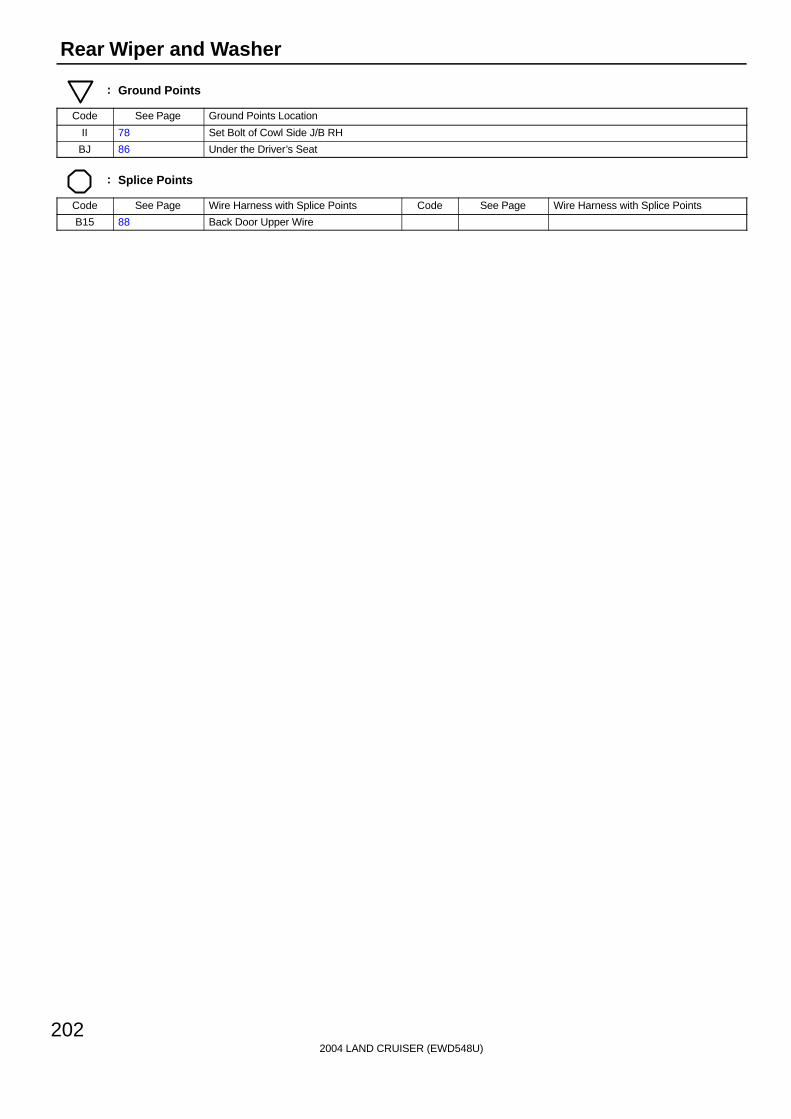
2004 LAND CRUISER (EWD548U)
202
Rear Wiper and Washer
: Ground Points
Code See Page Ground Points Location
II 78 Set Bolt of Cowl Side J/B RH
BJ 86 Under the Driver’s Seat
: Splice Points
Code See Page Wire Harness with Splice Points Code See Page Wire Harness with Splice Points
B15 88 Back Door Upper Wire

2004 LAND CRUISER (EWD548U)
203
Memo
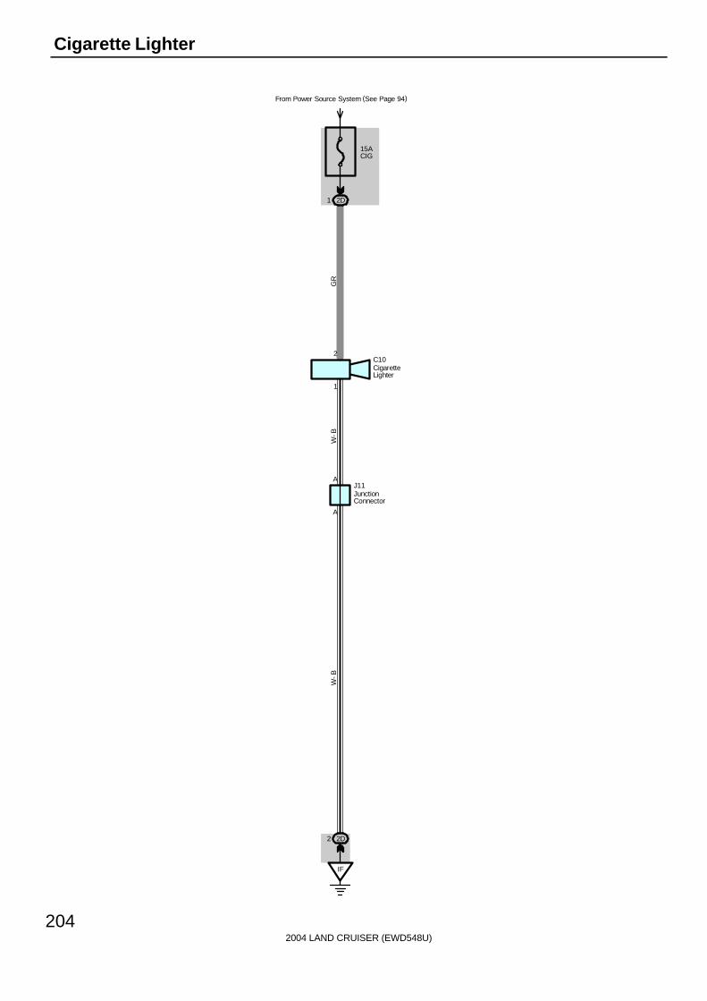
2004 LAND CRUISER (EWD548U)
204
Cigarette Lighter
15ACIG
From Power Source System (See Page 94)
2D1
1
2C10
A
A
IF
2D2
W-B
GR
W-B
J11
CigaretteLighter
JunctionConnector

2004 LAND CRUISER (EWD548U)
205
C10 Cigarette Lighter2-Ground : Approx. 12 volts with ignition SW at ACC or ON position1-Ground : Always continuity
: Parts Location
Code See Page Code See Page Code See Page
C10 70 J11 71
: Junction Block and Wire Harness Connector
Code See Page Junction Block and Wire Harness (Connector Location)
2D 28 Dash Wire and Cowl Side J/B LH (Left Kick Panel)
: Ground Points
Code See Page Ground Points Location
IF 78 Set Bolt of Cowl Side J/B LH
Service Hints
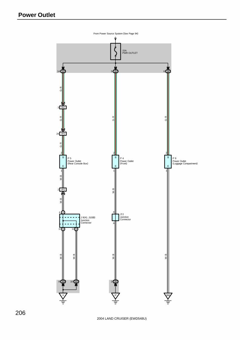
2004 LAND CRUISER (EWD548U)
206
Power Outlet
15APWR OUTLET
From Power Source System (See Page 94)
2D52D14 2K6
Ih13
IP224
1
2
E
B
IP22
BH BH
AF
II
3D8 3D10
B
E
1
2
B
E
1
2
A
A
2D2
IF BM
W-B
W-B
W-B
W-B
W-B
W-B
W-B
G-R
G-R
G-R
G-R
G-R
P 5 P 4 P 9
J11J 9(A), J10(B)
Power Outlet(Front)
Power Outlet(Rear Console Box)
Power Outlet(Luggage Compartment)
JunctionConnector
JunctionConnector

2004 LAND CRUISER (EWD548U)
207
P4 Power Outlet (Front)2-Ground : Approx. 12 volts with ignition SW at ACC or ON position1-Ground : Always continuity
P5 Power Outlet (Rear Console Box)2-Ground : Approx. 12 volts with ignition SW at ACC or ON position1-Ground : Always continuity
P9 Power Outlet (Luggage Compartment)2-Ground : Approx. 12 volts with ignition SW at ACC or ON position1-Ground : Always continuity
: Parts Location
Code See Page Code See Page Code See Page
J9 A 71 J11 71 P5 71
J10 B 71 P4 71 P9 73
: Junction Block and Wire Harness Connector
Code See Page Junction Block and Wire Harness (Connector Location)
2D 28 Dash Wire and Cowl Side J/B LH (Left Kick Panel)
2K 28 Floor No.1 Wire and Cowl Side J/B LH (Left Kick Panel)
3D 40 Dash Wire and Cowl Side J/B RH (Right Kick Panel)
: Connector Joining Wire Harness and Wire Harness
Code See Page Joining Wire Harness and Wire Harness (Connector Location)
IP2 80 Rear Console Box Wire and Dash Wire (Right Side of Rear Console)
Ih1 84 Dash Wire and Dash Wire (Center Side of Front Console)
: Ground Points
Code See Page Ground Points Location
IF 78 Set Bolt of Cowl Side J/B LH
II 78 Set Bolt of Cowl Side J/B RH
BM 86 Left Rear Side Quarter Panel
Service Hints

2004 LAND CRUISER (EWD548U)
208
Horn
10AHORN
From Power Source System (See Page 94)
1B21 1A4 1A15
2Q24
2B9
C
C
IH28
6
1 1
G-O
SB
SB
G-O G
-W
G-R
C
C18
H10H 9
Hor
n
Thef
t D
eter
rent
EC
U
HORNRelay
J14
SB
Combination SW
Horn LH Horn RH
Junc
tion
Con
nect
or
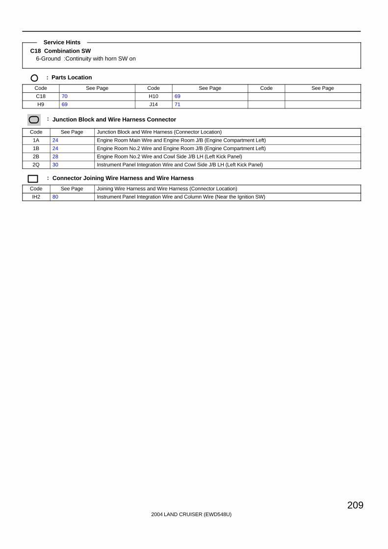
2004 LAND CRUISER (EWD548U)
209
C18 Combination SW6-Ground :Continuity with horn SW on
: Parts Location
Code See Page Code See Page Code See Page
C18 70 H10 69
H9 69 J14 71
: Junction Block and Wire Harness Connector
Code See Page Junction Block and Wire Harness (Connector Location)
1A 24 Engine Room Main Wire and Engine Room J/B (Engine Compartment Left)
1B 24 Engine Room No.2 Wire and Engine Room J/B (Engine Compartment Left)
2B 28 Engine Room No.2 Wire and Cowl Side J/B LH (Left Kick Panel)
2Q 30 Instrument Panel Integration Wire and Cowl Side J/B LH (Left Kick Panel)
: Connector Joining Wire Harness and Wire Harness
Code See Page Joining Wire Harness and Wire Harness (Connector Location)
IH2 80 Instrument Panel Integration Wire and Column Wire (Near the Ignition SW)
Service Hints

2004 LAND CRUISER (EWD548U)
210
Garage Door Opener
10ADOME
From Power Source System (See Page 94)
3Q17
2Q79
2L2
1
8
O 5
IF
2L14
SB
L-Y
W-B
GND
+B2
Overhead J/B
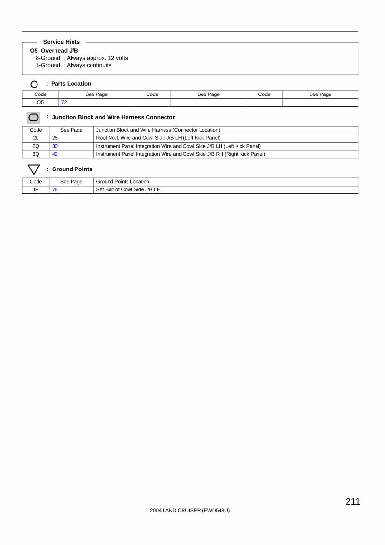
2004 LAND CRUISER (EWD548U)
211
O5 Overhead J/B8-Ground : Always approx. 12 volts1-Ground : Always continuity
: Parts Location
Code See Page Code See Page Code See Page
O5 72
: Junction Block and Wire Harness Connector
Code See Page Junction Block and Wire Harness (Connector Location)
2L 28 Roof No.1 Wire and Cowl Side J/B LH (Left Kick Panel)
2Q 30 Instrument Panel Integration Wire and Cowl Side J/B LH (Left Kick Panel)
3Q 42 Instrument Panel Integration Wire and Cowl Side J/B RH (Right Kick Panel)
: Ground Points
Code See Page Ground Points Location
IF 78 Set Bolt of Cowl Side J/B LH
Service Hints

2004 LAND CRUISER (EWD548U)
212
Electronically Controlled Transmission and A/T Indicator
E8
5C2
5D15
11
1 1
From Power Source System (See Page 94)
1B44
1A43 1B39
EA EE
2 1
4 5
2A5
2D34
B-Y
W-B
2D36
E1 E2
10AETCS
1B2
IG12
Id31
D6
25AEFI OR ECDNO. 1
1B11 1B3
E3
IG11
Id15B
-RB
-RB
-R
Y-B
Y-B
Y-B
B-W
B-R
B-Y
A18
If14
5
A21
6
A31
4
C3
2
C2
1
C17
( Shi
elde
d)
R W
3T16
BR- W
BR
-W
B- W
MREL
EFI
OR
EC
DR
elay
BATT +BM
B-Y
B-W
W-B
W-B
B-Y
B-Y
L-R
B-Y
B-Y
R-Y
Y-B
L-R
+B +B2 VC VTA1 VTA2 M+ M- GE01
M-M+VTA2VTAVC
E2
E 5(A), E 6(B), E 7(C), E 8(D), E 9(E)Engine Control Module
Throttle Control Motor and Sensor
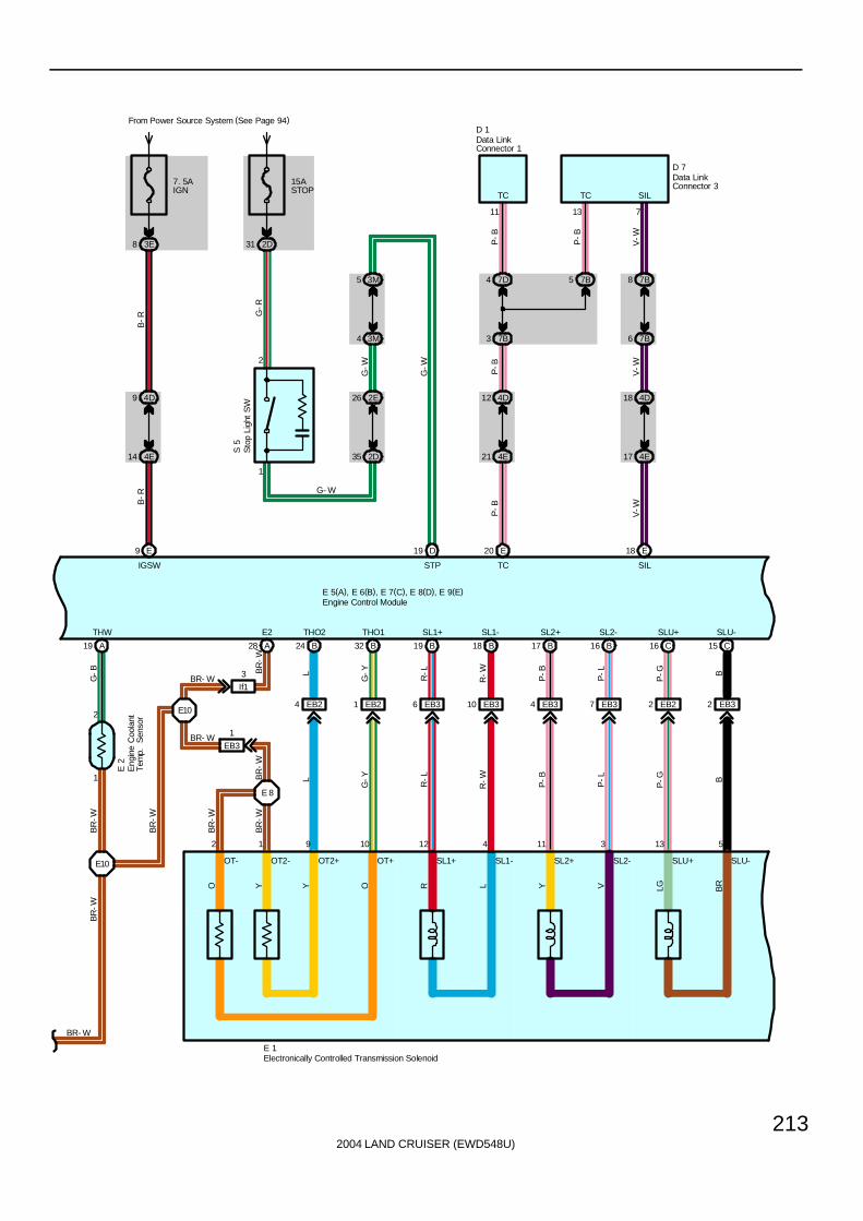
2004 LAND CRUISER (EWD548U)
213
7. 5AIGN
3E8
4D9
4E14
E9
B-R
B-R
15ASTOP
From Power Source System (See Page 94)
2D31
1
2
2E26
2D35
3M5
3M4
D19
S 5
G-W
4D12
4E21
7D4
7B3
P-B
E20
7B5
13
4D18
4E17
7B8
7B6
V-W
E18
711
A19
1
2
BR- W
O Y R
OT+OT2+ SLU-SLU+SL2-SL2+SL1-SL1+OT2-OT-
L Y V LG BRY O
A28
E 8
BR
-W
BR
-W
2 1 9 10 12 4 11 3 13 5
EB24
B24
LL
BR
-W
EB21
B32
G-Y
G-Y
EB36
B19
R-L
R-L
EB310
B18
R-W
R-W
EB34
B17
P-B
P-B
EB37
B16
P-L
P-L
EB22
C16
P-G
P-G
EB32
C15
BB
E 1
E10
E 2
G-B
BR
-W
BR
-W
BR
-W
THW E2 THO2 THO1 SL1+ SL2+ SL2-SL1- SLU+ SLU-
G-R
G-W
G- WP
-B
P-B
V-W
P-B
V-W
D 1
D 7
SILTCTC
SILTCSTPIGSW
E 5(A), E 6(B), E 7(C), E 8(D), E 9(E)
BR
-W
Data LinkConnector 1
Data LinkConnector 3
Electronically Controlled Transmission Solenoid
Eng
ine
Coo
lant
Tem
p.
Sen
sor
Engine Control Module
Sto
p Li
ght
SW
E10
If1
3
EB3
1
BR- W
BR- W

2004 LAND CRUISER (EWD548U)
214
Electronically Controlled Transmission and A/T Indicator
SLT+SLT-SRS2S1
W B SB
GR G
8
EB28
B11
RR
15
EB29
B10
WW
7
EB27
B15
GG
6
EB26
B12
G-B
G-B
14
EB23
B13
G-W
G-W
E 1
8
3P14
3M6
D23
12
3P13
3M2
D8
1
6C20
6C19
D10
6D27
6
6C16
6C17
D9
6D30
3P12
3M1
3P10
3M3
3
847521
LL2LDLNLRLPL
6D28
6C18
D20
6D17
6C1
E7
6D34
6C13
D11
6D13
6C4
E6
If11
R-B
R-B
R- L
EB210
B27
1
EB25
B35
2
B26
1
B34
2
L W R G
L W
T17 V 3
E 5(A), E 6(B), E 7(C), E 8(D), E 9(E)
G-Y
G-B
G-B
G-Y
G-Y
R-L
G-R
G-R
R-L
G-Y
G-B
10
A48
W- B
G-Y G G-B
G-R
G-W
G-W R-B
G-R G
G- B
W- B
S1 S2 SR SLT- SLT+
D
P 1
4 L P2 R N 3
RB
R- L
AT4 ATL NSSD NSSL E
NT+ NT- SP2+ SP2-
Electronically Controlled Transmission Solenoid
Engine Control Module
Park/Neutral Position SW
Vehicle Speed Sensor(Electronically Controlled Transmission)
Shift Lock Control ECU
Turbine Speed Sensor
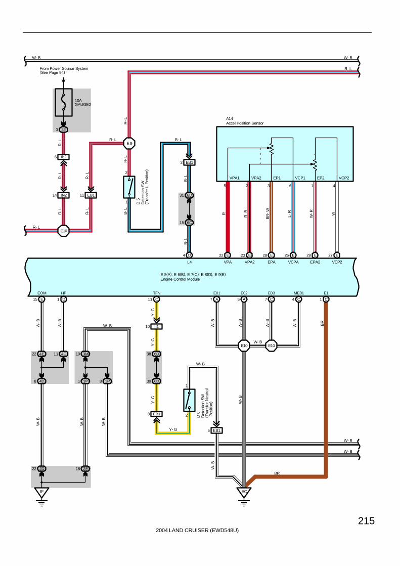
2004 LAND CRUISER (EWD548U)
215
4
E22 E23 E28 E26 29 E E27
2 3 165
A14
10AGAUGE2
3E3
Ib26
14 IN2
E10R- L
EB111
D4
6C15
6D31
1
2
E 9
EB13
R-L
R-L
From Power Source System(See Page 94)
E15
IF
2D22
22 4E
4D8
4C11 10 3M
3P1 8 3P
2E18
D1 C11
38 6D
6D39
8 EB1 2
1
EC
A6
E10 E10W- B
C7A7 C4 C1
D 6
E 5(A), E 6(B), E 7(C), E 8(D), E 9(E)
VPA1 VPA2 EP1 EP2VCP1 VCP2
R
R-B
BR
-W
L-R
W-R W
VPA VPA2 EPA VCPA EPA2 VCP2
R-L
R-L
B-L
R-L
R-L
R-L
R- L
B-L
B-L
B- L
L4
D 5
W-B
W-B
W-B
W-B
W-B
Y-G
Y-G
W-B
W-B
W-B
W-B BR
W-B
W- B
W- B
Y- G
W-B
BR
EOM HP TFN E01 E02 E03 ME01 E1
W- B
W- B
W- B W- B
R- L
Accel Position Sensor
Det
ectio
n S
W( T
rans
fer
L P
ositi
on)
Det
ectio
n S
W( T
rans
fer
Neu
tral
Pos
ition
)
Engine Control Module
EB15
Y-G
If110
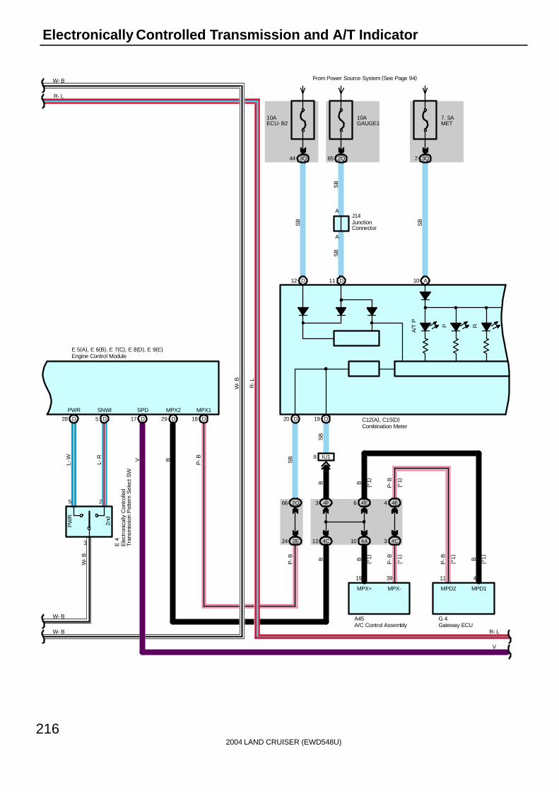
2004 LAND CRUISER (EWD548U)
216
Electronically Controlled Transmission and A/T Indicator
5 D28 D
2nd
PW
R
3
5 2
17 D D29 D18
E 5(A), E 6(B), E 7(C), E 8(D), E 9(E)
A/T
P
P R
10AGAUGE1
2Q65
7. 5AMET
3Q7
10AECU- B2
From Power Source System (See Page 94)
3Q44
D12 D11 A10
J14
D20 D19
IU19
4F32Q66
2E24 4C12 4A10 4C3
19 39 11 4
4E6 4E4
A45
R- L
G 4
V
C12(A), C15(D)
A
A
W- B
W- B
W- B
R- L
L-W
L-R V B
P-B
W-B
E 4
SB
PWR SNWI MPX1MPX2SPD
SB
B B P-B
B
P-B
P-B BB
P-B
( *1)
( *1)
( *1)
( *1)
( *1)
( *1)
MPD1MPD2MPX+ MPX-
SB
SB
SB
SB
W-B
R-L
Combination Meter
Ele
ctro
nica
lly C
ontr
olle
dT
rans
mis
sion
Pat
tern
Sel
ect S
W
Engine Control Module
Gateway ECUA/C Control Assembly
JunctionConnector

2004 LAND CRUISER (EWD548U)
217
N D 4 3 2 L
2nd
STR
T
A/T
OIL
TE
MP
EC
T P
WR
Spe
edom
eter
Tac
hom
eter
R- L
V
D15 D1 D16
3 2
B
IX16 8 IX1
10 EB1 EB19
R-G BR
SB
BR
2Q70
2E28
BBR
SB
SB
V
1V 2
R-G
SB
J14
C12(A), C15(D)
* 1 : w/ Navigation System
Combination Meter
Veh
icle
Spe
ed S
enso
r( C
ombi
natio
n M
eter
)
JunctionConnector
EC
BR
BR
2004 LAND CRUISER (EWD548U)
218
Electronically Controlled Transmission and A/T Indicator
Previous automatic transmissions have selected each gear shift using mechanically controlled throttle hydraulic pressure,governor hydraulic pressure and lock-up hydraulic pressure. The electronically controlled transmission, however, electricallycontrols the line pressure, throttle pressure, lock-up pressure and accumulator pressure etc. through the solenoid valve. Theelectronically controlled transmission is a system which precisely controls gear shift timing and lock-up timing in response tothe vehicle’s driving conditions and the engine condition detected by various sensors. It makes smooth driving possible byshift selection for each gear which is the most appropriate to the driving conditions at that time, and by preventing downing,squat and gear shift shock when starting off.
1. Gear Shift OperationWhen driving, the engine warm up condition is input as a signal to TERMINAL THW of the engine control module from theengine coolant temp. sensor and the vehicle speed signal from vehicle speed sensor is input to TERMINAL SP2+ of theengine control module. At the same time, the throttle valve opening signal from the throttle position sensor is input toTERMINALS VTA1 and VTA2 of the engine control module as throttle angle signal.Based on these signals, the engine control module selects the best shift position for the driving conditions and sends currentto the electronically controlled transmission solenoid.
2. Line Hydraulic Pressure ControlThe engine control module adjusts the line hydraulic pressure to the optimal level by controlling TERMINAL SLT+ of themodule according to the engine torque data. This realizes the smooth gear shifting.
3. High Response Gear Shifting ControlThe engine control module performs the high response engine torque up control to control the ignition-timing lag as well asopening the electronic throttle when shifting down. By doing this, the gear shifting is performed in a short period of time.Moreover, the engine control module uses the orifice switching control, which optimizes the speed of applying and reducingthe hydraulic pressure. And it realizes the fine shifting condition by applying and reducing hydraulic pressure slowly whenthe gear shifting shock is important and quickly when the high response is required.
4. Clutch Hydraulic Pressure ControlThe engine control module controls the clutch operation in the optimal timing and with the best hydraulic pressure accordingto the engine torque data and the number of the clutch revolution
5. Lock-Up and Flexible Lock-Up ControlThe engine control module carries out the lock-up control by controlling the TERMINAL SLU+ of the module according tothe shift position, vehicle speed, throttle opening degree and running conditions. The engine control module also steadilykeeps applying the lock-up clutch a delicate slippage to improve the transmission efficiency (Fuel efficiency) of the torqueconverter.
6. Stop Light SW CircuitIf the brake pedal is depressed (Stop light SW on) when driving in lock-up condition, a signal is input to TERMINAL STP ofthe engine control module. The engine control module operates and cuts the current to the solenoid to release lock-up.
7. Ai-Shift ControlThe engine control module judges whether the road is downslope or upslope by detecting the throttle opening degree or thevehicle’s speed. Moreover it can expect the winding roads by detecting the turning condition of the vehicle. The enginecontrol module keeps unnecessary shifting up from the fourth gear from operating and carries out the automatic shiftingdown to the third gear in order to control the vehicle running according to the road conditions. The engine control modulealso reads the driver’s intention during driving from his (her) accelerating operation and the running conditions of the vehicle.As a result of that, ideal shifting patters for each driver are automatically selected without any switching operations.
8. Electronically Controlled Transmission Pattern Select SW CircuitWhen the electronically controlled transmission pattern select SW is switched to PWR, a signal is input to TERMINAL PWRof the engine control module. This enables shift-up and shift-down at a higher speed range.
9. Transfer Shift OperationWhen the transfer shift lever is moved to L position, a signal is input into TERMINAL L4 of the engine control module.In addition when the transfer shift lever is moved to N position a signal is input to engine control module TERMINAL TFN.The engine control module detects the transfer condition through this.
System Outline
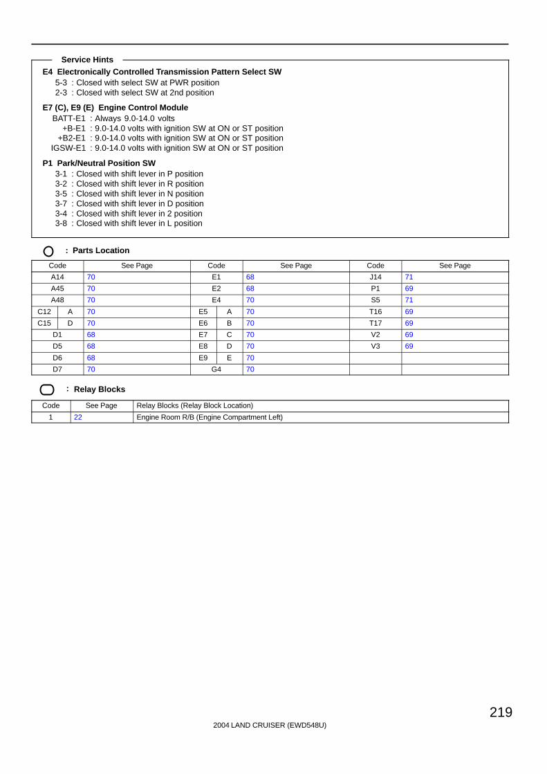
2004 LAND CRUISER (EWD548U)
219
E4 Electronically Controlled Transmission Pattern Select SW5-3 : Closed with select SW at PWR position2-3 : Closed with select SW at 2nd position
E7 (C), E9 (E) Engine Control ModuleBATT-E1 : Always 9.0-14.0 volts
+B-E1 : 9.0-14.0 volts with ignition SW at ON or ST position+B2-E1 : 9.0-14.0 volts with ignition SW at ON or ST position
IGSW-E1 : 9.0-14.0 volts with ignition SW at ON or ST position
P1 Park/Neutral Position SW3-1 : Closed with shift lever in P position3-2 : Closed with shift lever in R position3-5 : Closed with shift lever in N position3-7 : Closed with shift lever in D position3-4 : Closed with shift lever in 2 position3-8 : Closed with shift lever in L position
: Parts Location
Code See Page Code See Page Code See Page
A14 70 E1 68 J14 71
A45 70 E2 68 P1 69
A48 70 E4 70 S5 71
C12 A 70 E5 A 70 T16 69
C15 D 70 E6 B 70 T17 69
D1 68 E7 C 70 V2 69
D5 68 E8 D 70 V3 69
D6 68 E9 E 70
D7 70 G4 70
: Relay Blocks
Code See Page Relay Blocks (Relay Block Location)
1 22 Engine Room R/B (Engine Compartment Left)
Service Hints

2004 LAND CRUISER (EWD548U)
220
Electronically Controlled Transmission and A/T Indicator
: Junction Block and Wire Harness Connector
Code See Page Junction Block and Wire Harness (Connector Location)
1A 24 Engine Room Main Wire and Engine Room J/B (Engine Compartment Left)
1B 24 Engine Room No.2 Wire and Engine Room J/B (Engine Compartment Left)
2A 28 Engine Room No.2 Wire and Cowl Side J/B LH (Left Kick Panel)
2D28 Dash Wire and Cowl Side J/B LH (Left Kick Panel)
2E28 Dash Wire and Cowl Side J/B LH (Left Kick Panel)
2Q 30 Instrument Panel Integration Wire and Cowl Side J/B LH (Left Kick Panel)
3E 40
3M43
Dash Wire and Cowl Side J/B RH (Right Kick Panel)
3P43
( g )
3Q 42 Instrument Panel Integration Wire and Cowl Side J/B RH (Right Kick Panel)
4A
4C
4D 52 Dash Wire and J/B No.4 (Instrument Panel Center)
4E
( )
4F
5C 56 Dash Wire and J/B No.5 (Behind the Combination Meter)
5D 56 Engine Room No.2 Wire and J/B No.5 (Behind the Combination Meter)
6C 60 Dash Wire and J/B No.6 (Behind the Grove Box)
6D 60 Engine Wire and J/B No.6 (Behind the Grove Box)
7B 64 Dash Wire and J/B No.7 (Behind the Grove Box)
7D 64 Engine Room No.2 Wire and J/B No.7 (Behind the Grove Box)
: Connector Joining Wire Harness and Wire Harness
Code See Page Joining Wire Harness and Wire Harness (Connector Location)
EB1
EB2 76 Engine Wire and Transmission Wire (On the Transmission)
EB3
g ( )
IG1 78 Engine Room No.2 Wire and Dash Wire (Behind the Combination Meter)
IN2 80 Engine Wire and Dash Wire (Behind the Glove Box)
IU1 82 Instrument Panel Integration Wire and Dash Wire (Behind the Glove Box)
IX1 82 Instrument Panel Integration Wire and Engine Wire (Behind the Glove Box)
Ib2 84 Dash Wire and Dash Wire (Behind the Combination Meter)
Id184 Dash Wire and Dash Wire (Instrument Panel Center)
Id384 Dash Wire and Dash Wire (Instrument Panel Center)
If1 84 Engine Wire and Engine Wire (Behind the Glove Box)
: Ground Points
Code See Page Ground Points Location
EA 76 Front Right Side of Fender Apron
EC 76 Rear Bank of Right Cylinder Head
EE 76 Front Left Side of Fender Apron
IF 78 Set Bolt of Cowl Side J/B LH
: Splice Points
Code See Page Wire Harness with Splice Points Code See Page Wire Harness with Splice Points
E876 Transmission Wire
E10 76 Engine Wire
E976 Transmission Wire

2004 LAND CRUISER (EWD548U)
221
Memo
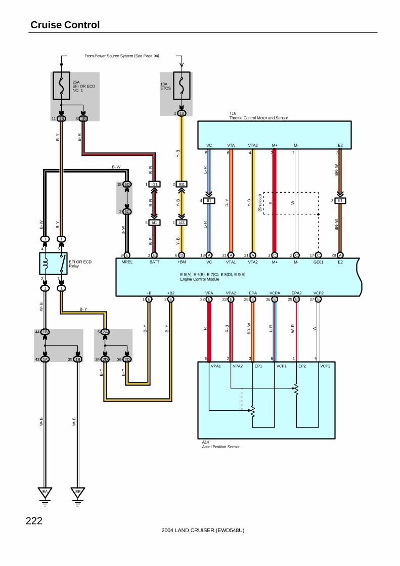
2004 LAND CRUISER (EWD548U)
222
Cruise Control
E8
2 5C
5D15
1
BATT
1
EFI OR ECDRelay
1 1
12
From Power Source System (See Page 94)
1B44
1A43 1B39
EA EE
4 5
2A5
2D34
W-B
2D36
E1 E2
25AEFI OR ECDNO. 1
1B11 1B3
E3
IG11
Id15
B-R
B-R
B-R
B-W
B-R
B-Y
B- W
MREL
B-Y
B-W
W-B
W-B
B-Y
B-Y
B-Y
B-Y
+B +B2
Y-B
Y-B
Y-B
1 Id3
2 IG1
6 D
+BM
B- Y
A18
VC
A21
VTA1
A31
VTA2
C3
M+
C2
M-
C17
GE01
A28
E2
If14 If13
10AETCS
1B2
5 36 4 2 1
R W
BR
-WB
R-W
Y-B
R-Y
L-R
L-R
T16
VC VTA VTA2 M+ M- E2
VCP2EPA2VCPAEPAVPA2VPA
W
W-R
L-R
BR
-W
R-BR
27 EE2926 E28 E23 E22 E
E 5(A), E 6(B), E 7(C), E 8(D), E 9(E)
VPA1 VPA2 EP1 VCP1 EP2 VCP2
5 2 3 6 1 4
A14
( Shi
elde
d)
Accel Position Sensor
Engine Control Module
Throttle Control Motor and Sensor
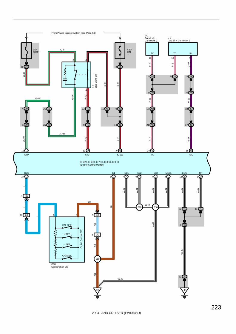
2004 LAND CRUISER (EWD548U)
223
1
2
4
3
E 5(A), E 6(B), E 7(C), E 8(D), E 9(E)
4D12
4E21
7D4
7B3
P-B
E20
7B5
13
4D18
4E17
7B8
7B6
V-W
E18
711
P-B
P-B
V-W
P-B
V-W
D 1
SILTCTC
SILTC
D 7
3M4
3M5
D19
G-W
STP
15ASTOP
2D31
2E
35 2D
26 4E
9 4C
13 4E15
14 4E
9 4D
7. 5AIGN
From Power Source System (See Page 94)
3E8
D12
ST1-
S 5
E9
IGSW
R-G
R-G
B-R
B-R
B-R
G-W
G-R
G- R
G- W
G- W
CANCEL
- SET
+ RES
ON- OFF
5
D24
CCS
Id34
II329 4 IH25
E10
EC
C1
E1
C18
LL
L
SB
BR
BR
BR
BR
A7
E01
A6
E02
C7
E03
C4
ME01
E10E10
W-B
W-B
W-B
W-B
W- B
W-B
IX25
Combination SW
Data LinkConnector 1 Data Link Connector 3
Engine Control Module
Sto
p Li
ght S
W
E15
EOM
IF
2D22
4E22
4D8
4C11
D1
HP
W-B
W-B
W-B
W- B
Cru
ise
Con
trol
SW

2004 LAND CRUISER (EWD548U)
224
Cruise Control
10AGAUGE2
3E3
11 EB1
Ib26
IN214
D
3
7
6D27
6C19
D10
G-Y
D
R-L
R-L
R-L
G-Y
E10
BR
Speedometer
9
C12(A), C15(D)
BR
SB
EB1
17 DD29 D18
CR
UIS
E
10AGAUGE1
2Q65
7. 5AMET
3Q7
10AECU- B2
From Power Source System (See Page 94)
3Q44
D12 D11 A10
J14
D20 D19
IU19
4F32Q66
2E24 4C12 4A10 4C3
19 39
4E6 4E4
A45
R-L
G 4
2
B2E28
2Q70
B
SB
SB
1
A
A
VB
P-B SB
MPX1MPX2 SPD
SB
B B
P-B
B
P-B
114
B
P-B
( *1)
( *1)
( *1)
( *1)
MPD2MPD1
MPX+ MPX-
SB
SB
SB
R-L
R-L
R-L
P 1
D16 D1
R-L SB
SB
J14
IX18
E 5(A), E 6(B), E 7(C), E 8(D), E 9(E)
* 1 : w/ Navigation System
Combination Meter
Engine Control Module
Gateway ECU
Par
k/N
eutra
lP
ositi
on S
W
A/C ControlAssembly
Junc
tion
Con
nect
or
JunctionConnector
R-G
R-G
IX16
10
3
EB1
D15
SB
Veh
icle
Spe
ed S
enso
r( C
ombi
natio
n M
eter
)
V 2
EC
BR
BR
BR

2004 LAND CRUISER (EWD548U)
225
The cruise control system is a constant vehicle speed controller which controls the opening angle of the engine throttle valveby the SW, and allows driving at a constant speed without depressing the accelerator pedal.
Set OperationWhen the ON-OFF SW is turned on, the systems starts preparations for cruise control and turns on the indicator light in thecombination meter.
Set Speed ControlWhen the - SET SW is operated with the ON-OFF SW turned on during driving, the speed is controlled at a constant speed.
Coast ControlWhen the - SET SW is kept turned on during cruise control driving, the engine control module controls the throttle valve todecelerate the vehicle speed.Every time the - SET SW is turned on instantaneously, the vehicle speed is decelerated approx. 1.5 km/h.
Accel ControlWhen the + RES SW is kept turned on during cruise control driving, the engine control module controls the throttle valve toaccelerate the vehicle speed.Every time the + RES SW is turned on instantaneously, the vehicle speed is accelerated approx. 1.5 km/h.
Resume ControlIf the vehicle speed is within the low speed limit (Approx. 40 km/h, 25 mph) when canceling the cruise control, operation ofthe + RES SW accelerates the vehicle speed and resumes the level before canceling the cruise control.
Manual Cancel MechanismIf any of the following signals are input during cruise control driving, the cruise control is canceled.∗ The stop light SW is on∗ The CANCEL SW is turned on∗ The ON-OFF SW is turned off
Auto Cancel FunctionIf any of the following conditions are detected, the cruise control is canceled:∗ Failure in the stop light SW wiring∗ Abnormality in the vehicle speed signal∗ Malfunction in the electronically controlled throttle parts
Overdrive FunctionThe overdrive may be canceled if the vehicle travels on a upward slope during cruise control driving. After the overdrive iscanceled, if the vehicle speed exceeds the overdrive return speed (Set speed ( 2 km/h, 1.2 mph) ) and it is determined thatthe slope has finished, and the vehicle returns to overdrive mode again.
E7 (C), E8 (D), E9 (E) Engine Control ModuleBATT-E1 : Always 9.0-14.0 voltsIGSW-E1 : 9.0-14.0 volts with ignition SW at ON or ST position
STP-E1 : 7.5-14 volts with brake pedal is depressed: Below 1.5 volts with brake pedal is released
C18 Combination SW5-4 : Approx. 1540 Ω with CANCEL SW on
: Approx. 240 Ω with + RES SW on: Approx. 630 Ω with - SET SW on
: Parts Location
Code See Page Code See Page Code See Page
A14 70 D7 70 G4 70
A45 70 E5 A 70 J14 71
C12 A 70 E6 B 70 P1 69
C15 D 70 E7 C 70 S5 71
C18 70 E8 D 70 T16 69
D1 68 E9 E 70 V2 69
System Outline
Service Hints

2004 LAND CRUISER (EWD548U)
226
Cruise Control
: Relay Blocks
Code See Page Relay Blocks (Relay Block Location)
1 22 Engine Room R/B (Engine Compartment Left)
: Junction Block and Wire Harness Connector
Code See Page Junction Block and Wire Harness (Connector Location)
1A 24 Engine Room Main Wire and Engine Room J/B (Engine Compartment Left)
1B 24 Engine Room No.2 Wire and Engine Room J/B (Engine Compartment Left)
2A 28 Engine Room No.2 Wire and Cowl Side J/B LH (Left Kick Panel)
2D28 Dash Wire and Cowl Side J/B LH (Left Kick Panel)
2E28 Dash Wire and Cowl Side J/B LH (Left Kick Panel)
2Q 30 Instrument Panel Integration Wire and Cowl Side J/B LH (Left Kick Panel)
3E 40Dash Wire and Cowl Side J/B RH (Right Kick Panel)
3M 43Dash Wire and Cowl Side J/B RH (Right Kick Panel)
3Q 42 Instrument Panel Integration Wire and Cowl Side J/B RH (Right Kick Panel)
4A
4C
4D 52 Dash Wire and J/B No.4 (Instrument Panel Center)
4E
( )
4F
5C 56 Dash Wire and J/B No.5 (Behind the Combination Meter)
5D 56 Engine Room No.2 Wire and J/B No.5 (Behind the Combination Meter)
6C 60 Dash Wire and J/B No.6 (Behind the Grove Box)
6D 60 Engine Wire and J/B No.6 (Behind the Grove Box)
7B 64 Dash Wire and J/B No.7 (Behind the Grove Box)
7D 64 Engine Room No.2 Wire and J/B No.7 (Behind the Grove Box)
: Connector Joining Wire Harness and Wire Harness
Code See Page Joining Wire Harness and Wire Harness (Connector Location)
EB1 76 Engine Wire and Transmission Wire (On the Transmission)
IG1 78 Engine Room No.2 Wire and Dash Wire (Behind the Combination Meter)
IH2 80 Instrument Panel Integration Wire and Column Wire (Near the Ignition SW)
II3 80 Dash Wire and Column Wire (Near the Ignition SW)
IN2 80 Engine Wire and Dash Wire (Behind the Glove Box)
IU1 82 Instrument Panel Integration Wire and Dash Wire (Behind the Glove Box)
IX182 Instrument Panel Integration Wire and Engine Wire (Behind the Glove Box)
IX282 Instrument Panel Integration Wire and Engine Wire (Behind the Glove Box)
Ib2 84 Dash Wire and Dash Wire (Behind the Combination Meter)
Id184 Dash Wire and Dash Wire (Instrument Panel Center)
Id384 Dash Wire and Dash Wire (Instrument Panel Center)
If1 84 Engine Wire and Engine Wire (Behind the Glove Box)
: Ground Points
Code See Page Ground Points Location
EA 76 Front Right Side of Fender Apron
EC 76 Rear Bank of Right Cylinder Head
EE 76 Front Left Side of Fender Apron
IF 78 Set Bolt of Cowl Side J/B LH
: Splice Points
Code See Page Wire Harness with Splice Points Code See Page Wire Harness with Splice Points
E10 76 Engine Wire

2004 LAND CRUISER (EWD548U)
227
Memo

2004 LAND CRUISER (EWD548U)
228
VSC
40AABSNO. 2
2
1
2 4
1 3
4 2
3 1
1 1 1 1 11
AB
S M
TR2
Rel
ay
AB
S M
TR1
Rel
ay
50AABSNO. 1
From Power Source System (See Page 94)
1
3 6
1 4
1
AB
S S
OL
Rel
ay
1 11
A1A19
A4
E13
A2B3
D3D2A29
7. 5AIGN
3B22
D22
A27 A21 A7 D16 D8 D7
B7 C8 C7 C10 C9 C4
10AECU- IG1
2B18
B6 B2
I 2
2
1
Buz
zer
RL-R
Y-B
W-L R
B-R Y
B-Y LG B-W
R-W
B-R
B-W
B-W L
B-W
PP
G-YP
B- R
P
R
W-L
R1+L-B
BS
SR
MR1
BM1BM2
Y-B
MR2 R2+
IG2
MTT SFLH SFLR SFRH SFRR SRLH
MTT SFLH SFLR SFRH SFRR SRLH
A37(A), A38(B), A39(C), A40(D)
A41(A), A42(B), A43(C), A44(D)
IG1 BZ
V 8
2
1
SB
2Q
16
ABS & BA & TRAC & VSC Actuator
ABS & BA & TRAC & VSC ECU
VS
C W
arni
ng B
uzze
r
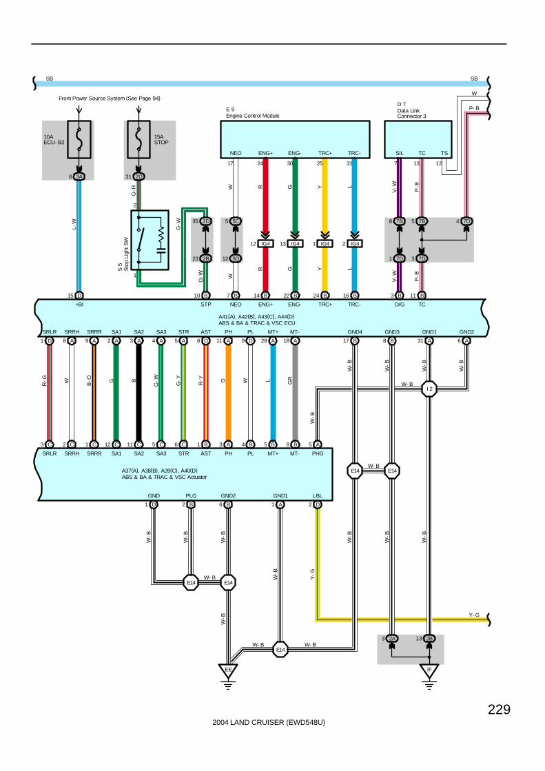
2004 LAND CRUISER (EWD548U)
229
D1
C3
15ASTOP
2D31
1
2
2B23
2D35
B10
S 5
5D12
5C5
B7
IG412 IG413 IG41 IG42
B14 B22 B24 B16
24 30 25 3117
W R G Y L
W
R G Y L
G-W
G-R
7D1
7B8
B3
V-W
7
V-W
7D3
7B5
B11
P-B
13
P-B
E 9D 7
10AECU- B2
From Power Source System (See Page 94)
3A8
D15
A8
C2
A9
C1
A2
C12
A3
C11
A4
C5
A5
C6
D6
B1
A11
A3
D9
B4
A28
B5
A18
B8 A5
A31 A6
I 2
IF
2B132A3
B17 B8
E14E14
D2A1B6
EE
E14
E14E14
B2D1
R-G
L-W
W B-O G B
G-W
G-Y
R-Y O W L GR
W-B
W-B
W-B
W-B
W-B
Y-G
W-B
W-B
W-B
W-B
W-B
W-B
W-B
W- B W- B
W- B
W- B
W-B
Y- G
SRLR
SRLR
A37(A), A38(B), A39(C), A40(D)
+BI STP NEO
NEO
ENG+ ENG- TRC+ TRC-
TRC-TRC+ENG-ENG+ SIL TC
D/G TC
W- B
SRRH SRRR SA1 SA2 SA3 STR AST PH PL MT+ MT-
MT-MT+PLPHASTSTRSA3SA2SA1SRRRSRRH PHG
LBLGND1GND2PLGGND
GND4 GND3 GND1 GND2
A41(A), A42(B), A43(C), A44(D)
G-W
SBSB
ABS & BA & TRAC & VSC Actuator
ABS & BA & TRAC & VSC ECU
Data LinkConnector 3Engine Control Module
Sto
p Li
ght S
W
7D4
12
TS
W
P- B
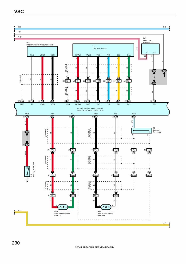
2004 LAND CRUISER (EWD548U)
230
VSC
2
A23 12 A A22 A10
W R B
3 2 1
( Shi
elde
d)
M 4
C18
IG422
(Shi
elde
d)( S
hiel
ded)
5 1 8
Y 1
C27
IG418
C28
IG420
C9
IG419
C19
IG421
C10
IG417
C22
IG416
6 2 4
R W B L Y G
R W B L Y G
Y- G
B13
1
2B4
2K27
R-W
R-W
P 8
16
B12
7D6
5 7D
D 1
B9
W-L
A
A
IA27IA25
12
W
A36
BD310 BD311
W
BF2
B21
BD38
W
IA26
BD39
BF21
B20
BB
B
( Shi
elde
d)( S
hiel
ded)
B W
A
J 2
6
IA214
12
G
A35
BD37
G
BF2
B19
G
IA215
BD36
BF25
B18
RR
R
( Shi
elde
d)( S
hiel
ded)
R G
( Shi
elde
d)
( Shi
elde
d)
A41(A), A42(B), A43(C), A44(D)
MSS E2 PMC VCM
GND VOUT VCC GYAW YAW2 VYS YD GL2 GL1
YSS GYAW YAW VYS YD GL2 GL1
WW
TS
TS
PKB
Y- G
RL+ RL- RR+ RR- RSS
IA216
SBSB
ABS Speed SensorRear LH
ABS Speed SensorRear RH
ABS & BA & TRAC & VSC ECU
Data LinkConnector 1
Master Cylinder Pressure Sensor
Par
king
Bra
ke S
W
Yaw Rate Sensor
JunctionConnector
W
P- B
7B2
11
TC
W
P-B

2004 LAND CRUISER (EWD548U)
231
From Power Source System (See Page 94)
3E3
PLGR
( Shi
elde
d)
( Shi
elde
d)
A13
A12 1
2
A14 A1315 A16 A
4
2
B
BB
W-R
25 A
L-W
D21
5D32
5C15
IG114 IG116 IG115
D20 C23 C14 C3
10AGAUGE2
6 Ib2
IN214
5 B
5D11
5C6
6C5
6D13
P 1
R-L
R-L
G-W
G-W
G-W
G- W
R- L
C15
IG113
IU413
B-R
C7
3B14
3Q26
C6
IG112
IU412
L-B
C4
3B18
3Q27
C5
3A11
3Q6
B1
3A4
3Q5
LG L-R
G W B-R L-R
L-B
L-W
Y-G R-L
SB
SB
SB
SB
SB
W
G
L- R
L- W
Y- G
P-B
SB
A41(A), A42(B), A43(C), A44(D)
FSS FL+ FL- FR+ FR-
J 2
P
Y- G
L-R G W SB
SB
SB
SB
SB
SB
+BO TRIG SS1- SS1+ EXI INFR WT IND VSCW BRL WA
SBSB
AB
S S
peed
Sen
sor
Fron
t LH
AB
S S
peed
Sen
sor
Fron
t RH
ABS & BA & TRAC & VSC ECU
Par
k/N
eutr
alP
ositi
on S
W
Junc
tion
Con
nect
or
C2
B-L
Det
ectio
n S
W( T
rans
fer
L P
ositi
on)
EXI2
Det
ectio
n S
W( C
ente
r D
iff.
Loc
k)
P
1
3
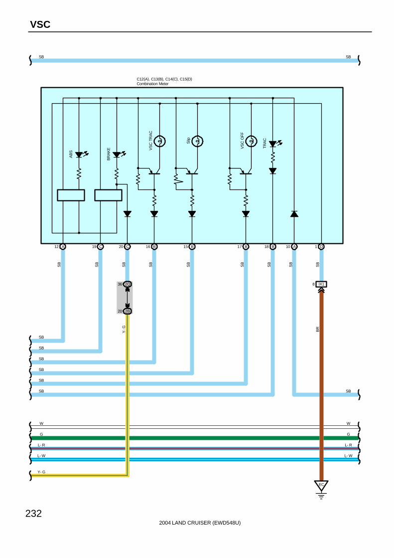
2004 LAND CRUISER (EWD548U)
232
VSC
AB
S
BR
AK
E VS
C T
RA
C
Slip
VS
C O
FF
TR
AC
EC
IX182Q36
2B20
SB
SB
W
G
L- R
L- W
SB
SB
SB
SB
SB
SB
W
G
L- R
L- W
Y- G
C12(A), C13(B), C14(C), C15(D)
A12
SB
SB
SB
SB
SB
SB
SB
SB
Y-G BR
C19 C20 B16 B15 B17 B18 A10 D1
SBSB
Combination Meter

2004 LAND CRUISER (EWD548U)
233
7 3Q
From Power Source System (See Page 94)
7. 5AMET
SB
IH26
9 IH2
IF
W
G
L- R
L- W
23 2Q
C17
3 11 10 9 2
1
SB
B-W
W G L-R
L-W
W-B
W G L-R
L-W
SB
SB
IG1
SS1+ SS1- TRIG BAT ESS
SB
7 II328 II327 II3 26 II3
Combination SW
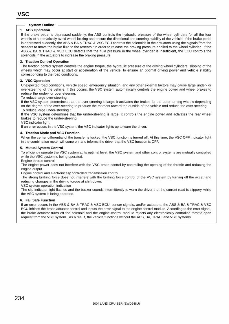
2004 LAND CRUISER (EWD548U)
234
VSC
1. ABS OperationIf the brake pedal is depressed suddenly, the ABS controls the hydraulic pressure of the wheel cylinders for all the fourwheels to automatically avoid wheel locking and ensure the directional and steering stability of the vehicle. If the brake pedalis depressed suddenly, the ABS & BA & TRAC & VSC ECU controls the solenoids in the actuators using the signals from thesensors to move the brake fluid to the reservoir in order to release the braking pressure applied to the wheel cylinder. If theABS & BA & TRAC & VSC ECU detects that the fluid pressure in the wheel cylinder is insufficient, the ECU controls thesolenoids in the actuators to increase the braking pressure.
2. Traction Control OperationThe traction control system controls the engine torque, the hydraulic pressure of the driving wheel cylinders, slipping of thewheels which may occur at start or acceleration of the vehicle, to ensure an optimal driving power and vehicle stabilitycorresponding to the road conditions.
3. VSC OperationUnexpected road conditions, vehicle speed, emergency situation, and any other external factors may cause large under- orover-steering of the vehicle. If this occurs, the VSC system automatically controls the engine power and wheel brakes toreduce the under- or over-steering.To reduce large over-steering :If the VSC system determines that the over-steering is large, it activates the brakes for the outer turning wheels dependingon the degree of the over-steering to produce the moment toward the outside of the vehicle and reduce the over-steering.To reduce large under-steering :If the VSC system determines that the under-steering is large, it controls the engine power and activates the rear wheelbrakes to reduce the under-steering.VSC indicator lightIf an error occurs in the VSC system, the VSC indicator lights up to warn the driver.
4. Traction Mode and VSC FunctionWhen the center differential of the transfer is locked, the VSC function is turned off. At this time, the VSC OFF indicator lightin the combination meter will come on, and informs the driver that the VSC function is OFF.
5. Mutual System ControlTo efficiently operate the VSC system at its optimal level, the VSC system and other control systems are mutually controlledwhile the VSC system is being operated.Engine throttle controlThe engine power does not interfere with the VSC brake control by controlling the opening of the throttle and reducing theengine output.Engine control and electronically controlled transmission controlThe strong braking force does not interfere with the braking force control of the VSC system by turning off the accel. andreducing changes in the driving torque at shift-down.VSC system operation indicationThe slip indicator light flashes and the buzzer sounds intermittently to warn the driver that the current road is slippery, whilethe VSC system is being operated.
6. Fail Safe FunctionIf an error occurs in the ABS & BA & TRAC & VSC ECU, sensor signals, and/or actuators, the ABS & BA & TRAC & VSCECU inhibits the brake actuator control and inputs the error signal to the engine control module. According to the error signal,the brake actuator turns off the solenoid and the engine control module rejects any electronically controlled throttle openrequest from the VSC system. As a result, the vehicle functions without the ABS, BA, TRAC, and VSC systems.
System Outline
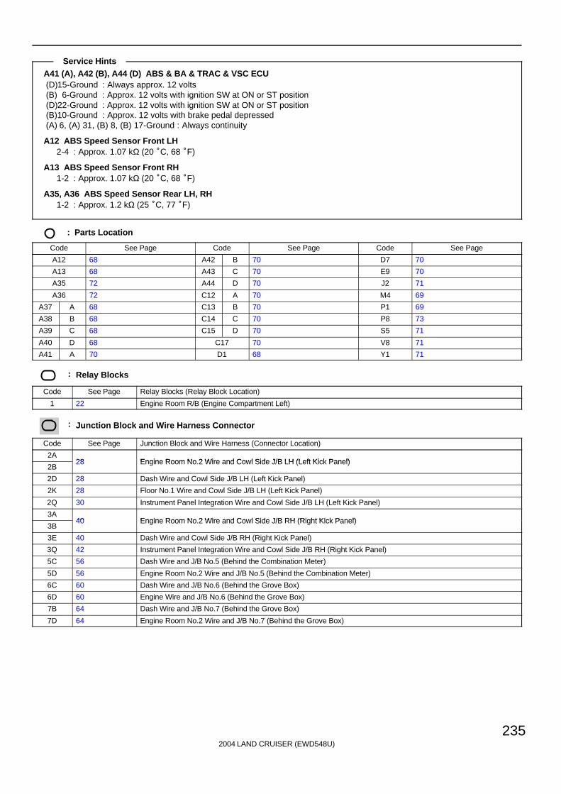
2004 LAND CRUISER (EWD548U)
235
A41 (A), A42 (B), A44 (D) ABS & BA & TRAC & VSC ECU(D)15-Ground : Always approx. 12 volts(B) 6-Ground : Approx. 12 volts with ignition SW at ON or ST position(D)22-Ground : Approx. 12 volts with ignition SW at ON or ST position(B)10-Ground : Approx. 12 volts with brake pedal depressed(A) 6, (A) 31, (B) 8, (B) 17-Ground : Always continuity
A12 ABS Speed Sensor Front LH2-4 : Approx. 1.07 kΩ (20 °C, 68 °F)
A13 ABS Speed Sensor Front RH1-2 : Approx. 1.07 kΩ (20 °C, 68 °F)
A35, A36 ABS Speed Sensor Rear LH, RH1-2 : Approx. 1.2 kΩ (25 °C, 77 °F)
: Parts Location
Code See Page Code See Page Code See Page
A12 68 A42 B 70 D7 70
A13 68 A43 C 70 E9 70
A35 72 A44 D 70 J2 71
A36 72 C12 A 70 M4 69
A37 A 68 C13 B 70 P1 69
A38 B 68 C14 C 70 P8 73
A39 C 68 C15 D 70 S5 71
A40 D 68 C17 70 V8 71
A41 A 70 D1 68 Y1 71
: Relay Blocks
Code See Page Relay Blocks (Relay Block Location)
1 22 Engine Room R/B (Engine Compartment Left)
: Junction Block and Wire Harness Connector
Code See Page Junction Block and Wire Harness (Connector Location)
2A28 Engine Room No 2 Wire and Cowl Side J/B LH (Left Kick Panel)
2B28 Engine Room No.2 Wire and Cowl Side J/B LH (Left Kick Panel)
2D 28 Dash Wire and Cowl Side J/B LH (Left Kick Panel)
2K 28 Floor No.1 Wire and Cowl Side J/B LH (Left Kick Panel)
2Q 30 Instrument Panel Integration Wire and Cowl Side J/B LH (Left Kick Panel)
3A40 Engine Room No 2 Wire and Cowl Side J/B RH (Right Kick Panel)
3B40 Engine Room No.2 Wire and Cowl Side J/B RH (Right Kick Panel)
3E 40 Dash Wire and Cowl Side J/B RH (Right Kick Panel)
3Q 42 Instrument Panel Integration Wire and Cowl Side J/B RH (Right Kick Panel)
5C 56 Dash Wire and J/B No.5 (Behind the Combination Meter)
5D 56 Engine Room No.2 Wire and J/B No.5 (Behind the Combination Meter)
6C 60 Dash Wire and J/B No.6 (Behind the Grove Box)
6D 60 Engine Wire and J/B No.6 (Behind the Grove Box)
7B 64 Dash Wire and J/B No.7 (Behind the Grove Box)
7D 64 Engine Room No.2 Wire and J/B No.7 (Behind the Grove Box)
Service Hints
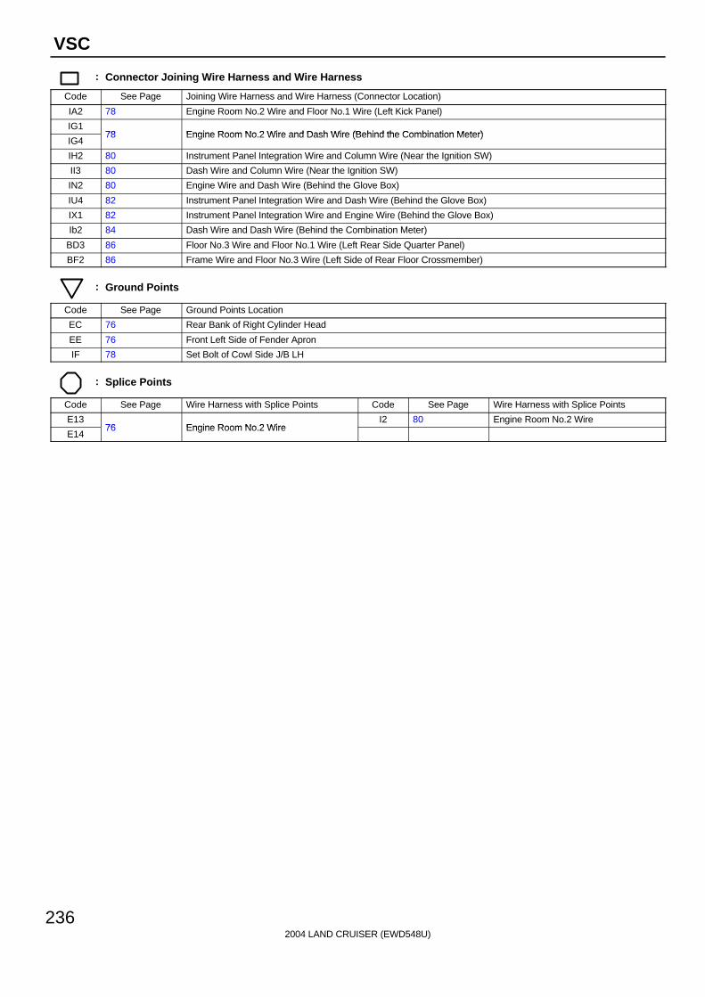
2004 LAND CRUISER (EWD548U)
236
VSC
: Connector Joining Wire Harness and Wire Harness
Code See Page Joining Wire Harness and Wire Harness (Connector Location)
IA2 78 Engine Room No.2 Wire and Floor No.1 Wire (Left Kick Panel)
IG178 Engine Room No 2 Wire and Dash Wire (Behind the Combination Meter)
IG478 Engine Room No.2 Wire and Dash Wire (Behind the Combination Meter)
IH2 80 Instrument Panel Integration Wire and Column Wire (Near the Ignition SW)
II3 80 Dash Wire and Column Wire (Near the Ignition SW)
IN2 80 Engine Wire and Dash Wire (Behind the Glove Box)
IU4 82 Instrument Panel Integration Wire and Dash Wire (Behind the Glove Box)
IX1 82 Instrument Panel Integration Wire and Engine Wire (Behind the Glove Box)
Ib2 84 Dash Wire and Dash Wire (Behind the Combination Meter)
BD3 86 Floor No.3 Wire and Floor No.1 Wire (Left Rear Side Quarter Panel)
BF2 86 Frame Wire and Floor No.3 Wire (Left Side of Rear Floor Crossmember)
: Ground Points
Code See Page Ground Points Location
EC 76 Rear Bank of Right Cylinder Head
EE 76 Front Left Side of Fender Apron
IF 78 Set Bolt of Cowl Side J/B LH
: Splice Points
Code See Page Wire Harness with Splice Points Code See Page Wire Harness with Splice Points
E1376 Engine Room No 2 Wire
I2 80 Engine Room No.2 Wire
E1476 Engine Room No.2 Wire

2004 LAND CRUISER (EWD548U)
237
SRS
NOTICE: When inspecting or repairing the SRS, perform the operation in accordance with the following precautionaryinstructions and the procedure and precautions in the Repair Manual for the applicable model year.
Malfunction symptoms of the SRS are difficult to confirm, so the DTCs become the most important source of informationwhen troubleshooting. When troubleshooting the SRS, always inspect the DTCs before disconnecting the battery.
Work must be started after 90 seconds from when the ignition switch is turned to the ”LOCK” position and thenegative (-) terminal cable is disconnected from the battery.(The SRS is equipped with a back-up power source so that if work is started within 90 seconds fromdisconnecting the negative (-) terminal cable of the battery, the SRS may be deployed.)
When the negative (-) terminal cable is disconnected from the battery, the memory of the clock and audio system will becanceled. So before starting work, make a record of the contents memorized in the audio memory system. When work isfinished, reset the audio systems as they were before and adjust the clock. This vehicle has power tilt and powertelescopic steering, power seat and power outside rear view mirror which are all equipped with memory function.However, it is not possible to make a record of the memory contents. So when the work is finished, it will be necessaryto explain this fact tot the customer, and ask the customer to adjust the features and reset the memory. To avoid erasingthe memory in each memory system, never use a back-up power supply from outside the vehicle.
Before repairs, remove the airbag sensor if shocks are likely to be applied to the sensor during repairs.
Do not expose the steering wheel pad, front passenger airbag assembly, side airbag assembly, curtain shield airbagassembly, seat belt pretensioner, center airbag sensor assembly, front airbag sensor assembly or side airbag sensorassembly directly to hot air or flames.
Even in cases of a minor collision where the SRS does not deploy, the steering wheel pad, front passenger airbagassembly, side airbag assembly, curtain shield airbag assembly, seat belt pretensioner, center airbag sensor assembly,front airbag sensor assembly and side airbag sensor assembly should be inspected.
Never use SRS parts from another vehicle. When replacing parts, replace them with new parts.
Never disassemble and repair the steering wheel pad, front passenger airbag assembly, side airbag assembly, curtainshield airbag assembly, seat belt pretensioner, center airbag sensor assembly, front airbag sensor assembly or sideairbag sensor assembly in order to reuse it.
If the steering wheel pad, front passenger airbag assembly, side airbag assembly, curtain shield airbag assembly, seatbelt pretensioner, center airbag sensor assembly, front airbag sensor assembly or side airbag sensor assembly hasbeen dropped, or if there are cracks, dents or other defects in the case, bracket or connector, replace them with newones.
Use a volt/ohmmeter with high impedance (10 kΩ/V minimum) for troubleshooting the system’s electrical circuits.
Information labels are attached to the periphery of the SRS components. Follow the instructions on the notices.
After work on the SRS is completed, perform the SRS warning light check.
If the vehicle is equipped with a mobile communication system, refer to the precaution in the IN section of the RepairManual.
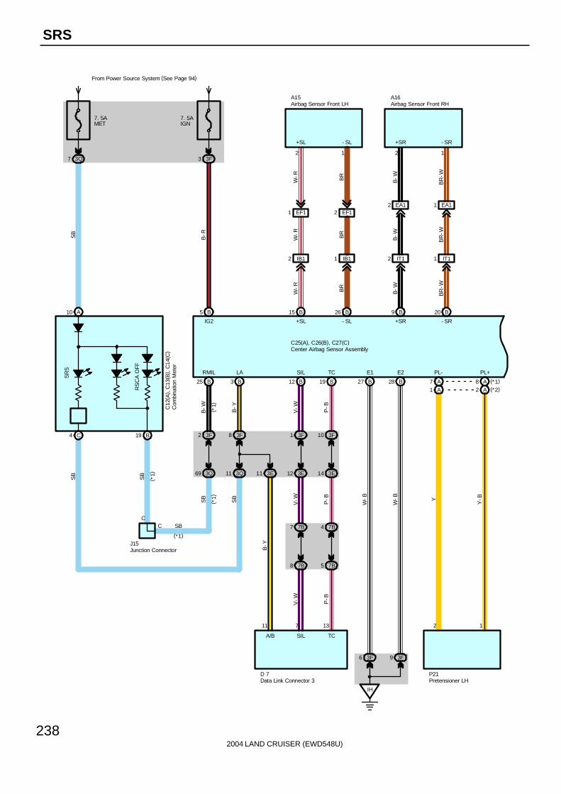
2004 LAND CRUISER (EWD548U)
238
SRS
RS
CA
OFF
SR
S
A10
C4 B19
7. 5AMET
3Q7
C12
( A) ,
C13
( B) ,
C14
( C)
SB
B25
3F2
3Q69
B3
3F8
3Q11 3E11
B12
3F1
3E12
B19
3F10
3E14
J15
7B7
7B8
7B4
7B5
7 1311
D 7
IH
3F6 3F9
B27 B28 A7A1
A8 (*1)
A2 (*2)
2 1
P21
B5
7. 5AIGN
From Power Source System (See Page 94)
3F3
B20B9
IT12 IT11
2 1
A16
B26B15
IB12 IB11
EF11 EF12
12
A15
C25(A), C26(B), C27(C)
B-R
W-R BR
B-W
BR
-W
W-R BR
B-W
BR
-W
W-R BR
B-W
BR
-W
B-W B-Y
V-W P-B
P-B
V-W
B-Y
SB
SB
SB
SB
V-W P-B
W-B
W-B Y
Y-B
CC SB
IG2 +SL
+SL - SL
- SL
+SR - SR
+SR - SR
( *1)
( *1)
(*1)
( *1)
RMIL LA SIL TC E1 E2 PL- PL+
A/B SIL TC
EA12 EA11
Airbag Sensor Front LH Airbag Sensor Front RH
Com
bina
tion
Met
er
Data Link Connector 3 Pretensioner LH
Center Airbag Sensor Assembly
Junction Connector
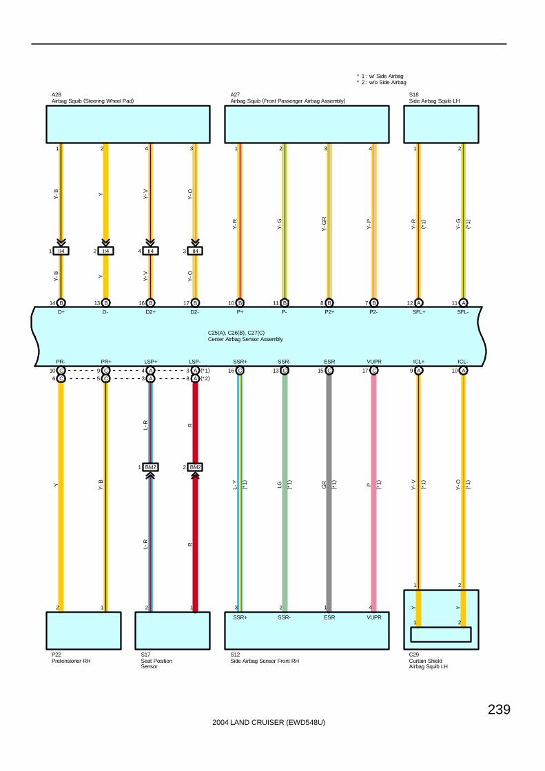
2004 LAND CRUISER (EWD548U)
239
C10C6
C9C5
2 1
P22
A4A3
A3 (*1)
A8 (*2)
2 1
S17
BM21 BM22
B14 B13 B16 B17
1 2 4 3
A28
II41 II42 II44 II43
B10 B11 B8 B7
1 2 3 4
A27
A11A12
21
S18
C16 C13 C15 C17
3 2 1 4
A9 A10
1 2
Y Y
C25(A), C26(B), C27(C)
Y-B Y
Y-V
Y-O
Y-B Y
Y-V
Y-O
Y-R
Y-G
Y-G
R
Y-P
Y-R
Y-G
Y
Y-B
L-R R
L-R R
L-Y
LG GR P
Y-V
Y-O
D+ D- D2+ D2- P+ P- P2+ P2-
PR- PR+ LSP+ LSP-
* 2 : w/o Side Airbag* 1 : w/ Side Airbag
( *1)
( *1)
SFL+ SFL-
S12 C29
(*1)
( *1)
( *1)
( *1)
( *1)
( *1)
SSR+ SSR- ESR VUPR ICL+ ICL-
SSR+ SSR- ESR VUPR21
Airbag Squib (Front Passenger Airbag Assembly)Airbag Squib (Steering Wheel Pad)
Pretensioner RH
Side Airbag Squib LH
Curtain ShieldAirbag Squib LH
Center Airbag Sensor Assembly
Side Airbag Sensor Front RHSeat PositionSensor

2004 LAND CRUISER (EWD548U)
240
SRS
S11
3
A
1
16
42
A20 1817 A A C6C5
21
S19
18 4 C
3
20CC C19
2 1 4
C8 C7
1 2
Y Y
3D30
4E19
14
3F5
4C4
SB
G-W
BB
IU18
IF
IF13
4
3
C
2Q43
C
( *1)
( *1)
E 9
F/PS
S14 C30
C25(A), C26(B), C27(C)
G-W
L-W
LG-B
GR
-L
P-L
Y-R
Y-G
L-W
LG-B
GR
-R
L-B
Y-V
Y-O
( *1)
( *1)
( *1)
( *1)
SSL+ SSL- ESL VUPL
SSL+ SSL- ESL VUPL
S13
3
A
1
14
42
A1 1315 A A
L-Y
LG-B G R( *1)
( *1)
( *1)
( *1)
CSL+ CSL- ESCL VUCL
CSL+ CSL- ESCL VUCL
W-B
SB
( *1)
( *1)
SFR+ SFR-
( *1)
( *1)
( *1)
( *1)
( *1)
( *1)
CSR+ CSR- ESCR VUCR ICR+ ICR-
CSR+ CSR- ESCR VUCR
( *1)
( *1)
( *1)
1 2
Engine ControlModule
Side Airbag Sensor Front LH Side Airbag Sensor Rear LH
Center Airbag Sensor Assembly
Side Airbag Squib RH
Side Airbag Sensor Rear RH Curtain ShieldAirbag Squib RH
Rol
l Sen
sing
of
Cur
tain
Shi
eld
Airb
ags
Cut
off S
W
R40
B23
GSW2
B
RMSW
21 B
Ia11
G-W ( *1)
SB
IF211
A
A
SB
( *1)
( *1)
Junc
tion
Con
nect
or
J 7
Junc
tion
Con
nect
or
J12
G- W
(*1)
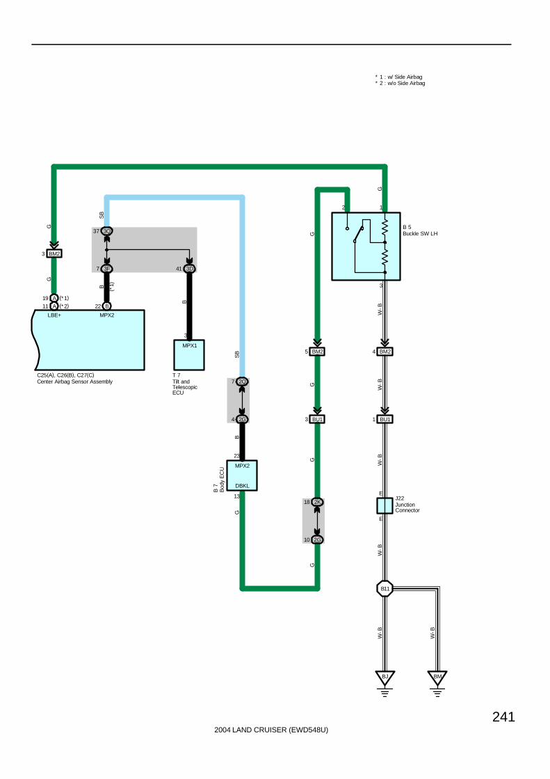
2004 LAND CRUISER (EWD548U)
241
BM23
A11
W-BG
W-B
G
W-B
G
GG
C25(A), C26(B), C27(C)
10 2G
2K18
BU13
5 BM2
BJ
B11
BM
BU11
4 BM2
3
E
2 1
EJ22
B 5
W-B
W-B
W-B
G
LBE+
A19 (*1)(*2)
* 1 : w/ Side Airbag* 2 : w/o Side Airbag
Buckle SW LH
JunctionConnector
Center Airbag Sensor Assembly
DBKL
22 B
B
MPX2
(*1)
2G4
2Q7
MPX1
3
T 7Tilt andTelescopicECU
3D41
B
MPX2
3F7
3Q37B
SB
SB
G
G
Bod
y E
CU
B 7
13
23

2004 LAND CRUISER (EWD548U)
242
SRS
∗ The SRS airbag are provided for the driver and front passenger. The SRS airbags have been designed to help reducingthe shocks to the heads and chests of the driver and front passenger in the event of a severe frontal impact collision assupplements to the seat belts.This system is a 3-sensor type airbag system to detect the impact during a front collision using the center airbag sensorassembly and airbag sensor front LH, RH, and to make the airbag system and pretensioner operate as well.
∗ In this system, a front side collision is detected by the side airbag sensor front LH, RH in order to simultaneously deploythe side and curtain shield airbags. A rear side collision is detected by the side airbag sensor rear LH, RH in order todeploy only the curtain shield airbag.
∗ Roll sensing of curtain shield airbags control has been adopted in order to deploy the curtain shield airbags and thepretensioners for the driver and front passenger, in the event that the vehicle rolls over.A roll sensing of curtain shield airbags cutoff SW is provided on the driver side of the instrument panel to enable the driverto disable this system.
∗ Dual-stage SRS airbags system, that controls the airbag inflating output optimum by judging the extent of impact and seatposition (Driver seat), has been used for the driver and front passenger airbags.
∗ In accordance with the adoption of the dual-stage SRS airbag system, a seat position sensor has been established for thedriver seat.
∗ This system has adopted a fuel cut control that stops the fuel pump when the airbag is deployed.
: Parts Location
Code See Page Code See Page Code See Page
A15 68 C27 C 70 R40 71
A16 68 C29 72 S11 73
A27 70 C30 72 S12 73
A28 70 D7 70 S13 73
B5 74 E9 70 S14 73
B7 70 J7 71 S17 74
C12 A 70 J12 71 S18 74
C13 B 70 J15 71 S19 74
C14 C 70 J22 72 T7 71
C25 A 70 P21 73
C26 B 70 P22 73
: Junction Block and Wire Harness Connector
Code See Page Junction Block and Wire Harness (Connector Location)
2G 28 Dash Wire and Cowl Side J/B LH (Left Kick Panel)
2K 28 Floor No.1 Wire and Cowl Side J/B LH (Left Kick Panel)
2Q 30 Instrument Panel Integration Wire and Cowl Side J/B LH (Left Kick Panel)
3D
3E 40 Dash Wire and Cowl Side J/B RH (Right Kick Panel)
3F
( g )
3Q 42 Instrument Panel Integration Wire and Cowl Side J/B RH (Right Kick Panel)
4C52 Dash Wire and J/B No 4 (Instrument Panel Center)
4E52 Dash Wire and J/B No.4 (Instrument Panel Center)
7B 64 Dash Wire and J/B No.7 (Behind the Grove Box)
System Outline
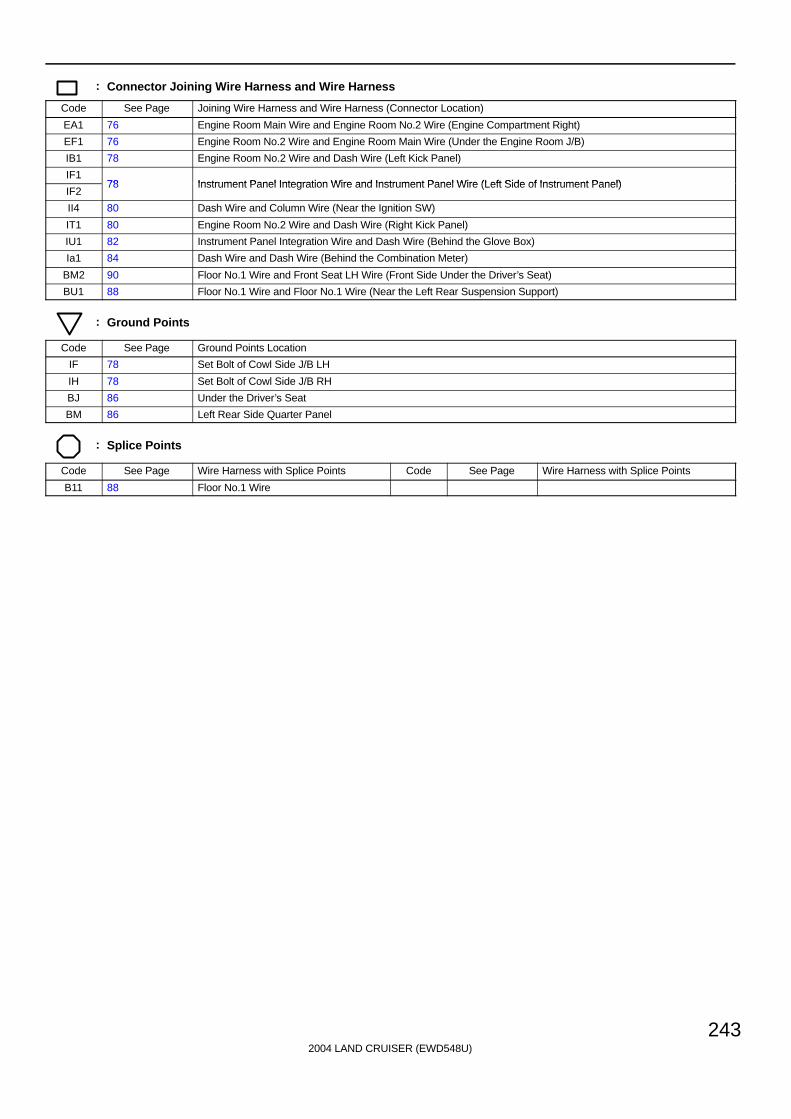
2004 LAND CRUISER (EWD548U)
243
: Connector Joining Wire Harness and Wire Harness
Code See Page Joining Wire Harness and Wire Harness (Connector Location)
EA1 76 Engine Room Main Wire and Engine Room No.2 Wire (Engine Compartment Right)
EF1 76 Engine Room No.2 Wire and Engine Room Main Wire (Under the Engine Room J/B)
IB1 78 Engine Room No.2 Wire and Dash Wire (Left Kick Panel)
IF178 Instrument Panel Integration Wire and Instrument Panel Wire (Left Side of Instrument Panel)
IF278 Instrument Panel Integration Wire and Instrument Panel Wire (Left Side of Instrument Panel)
II4 80 Dash Wire and Column Wire (Near the Ignition SW)
IT1 80 Engine Room No.2 Wire and Dash Wire (Right Kick Panel)
IU1 82 Instrument Panel Integration Wire and Dash Wire (Behind the Glove Box)
Ia1 84 Dash Wire and Dash Wire (Behind the Combination Meter)
BM2 90 Floor No.1 Wire and Front Seat LH Wire (Front Side Under the Driver’s Seat)
BU1 88 Floor No.1 Wire and Floor No.1 Wire (Near the Left Rear Suspension Support)
: Ground Points
Code See Page Ground Points Location
IF 78 Set Bolt of Cowl Side J/B LH
IH 78 Set Bolt of Cowl Side J/B RH
BJ 86 Under the Driver’s Seat
BM 86 Left Rear Side Quarter Panel
: Splice Points
Code See Page Wire Harness with Splice Points Code See Page Wire Harness with Splice Points
B11 88 Floor No.1 Wire
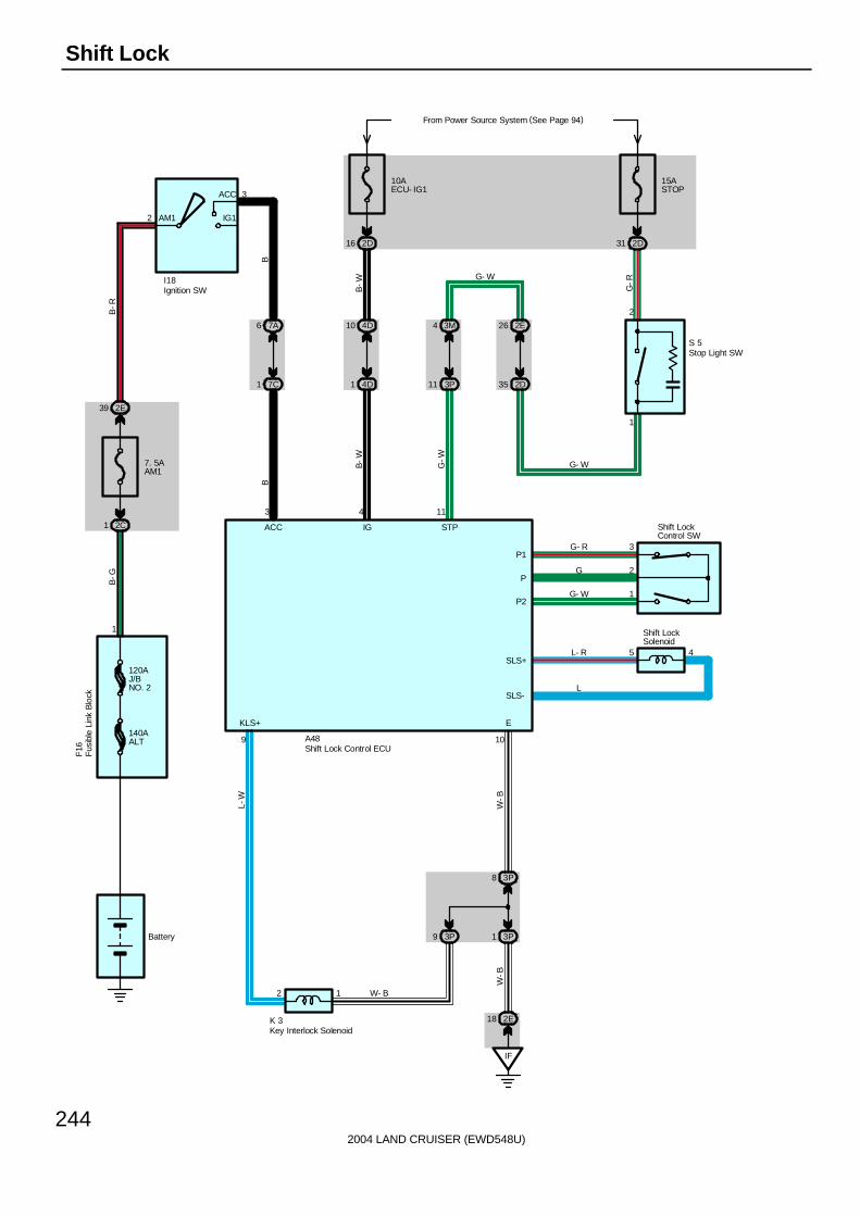
2004 LAND CRUISER (EWD548U)
244
Shift Lock
IF
3P8
3P13P9
2 1
109
5 4
3
2
1
10AECU- IG1
2D16
4D10
4D1
4
From Power Source System (See Page 94)
2D31
1
2
3M4
3P11
11
2E26
2D35
G-R
B-W
B-W
G-W
G- W
G- W
G- R
G
G- W
L- R
L
W- B
W-B
L-W
W-B
K 3
15ASTOP
S 5
A48
IG STP
EKLS+
P1
P
P2
SLS+
SLS-
Shift LockControl SW
Shift LockSolenoid
2E18Key Interlock Solenoid
Stop Light SW
Shift Lock Control ECU
2
3
AM1
ACC
IG1
B-R
B-G
BB
2E39
7. 5AAM1
2C1
1
120AJ/BNO. 2
140AALT
Fus
ible
Lin
k B
lock
F16
Ignition SWI18
Battery
3
ACC
7A6
7C1
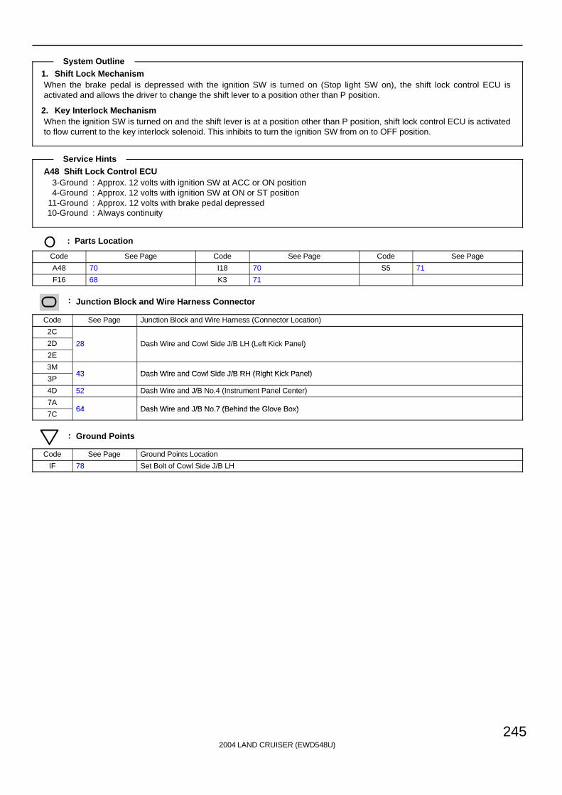
2004 LAND CRUISER (EWD548U)
245
1. Shift Lock MechanismWhen the brake pedal is depressed with the ignition SW is turned on (Stop light SW on), the shift lock control ECU isactivated and allows the driver to change the shift lever to a position other than P position.
2. Key Interlock MechanismWhen the ignition SW is turned on and the shift lever is at a position other than P position, shift lock control ECU is activatedto flow current to the key interlock solenoid. This inhibits to turn the ignition SW from on to OFF position.
A48 Shift Lock Control ECU3-Ground : Approx. 12 volts with ignition SW at ACC or ON position4-Ground : Approx. 12 volts with ignition SW at ON or ST position
11-Ground : Approx. 12 volts with brake pedal depressed10-Ground : Always continuity
: Parts Location
Code See Page Code See Page Code See Page
A48 70 I18 70 S5 71
F16 68 K3 71
: Junction Block and Wire Harness Connector
Code See Page Junction Block and Wire Harness (Connector Location)
2C
2D 28 Dash Wire and Cowl Side J/B LH (Left Kick Panel)
2E
( )
3M43 Dash Wire and Cowl Side J/B RH (Right Kick Panel)
3P43 Dash Wire and Cowl Side J/B RH (Right Kick Panel)
4D 52 Dash Wire and J/B No.4 (Instrument Panel Center)
7A64 Dash Wire and J/B No 7 (Behind the Glove Box)
7C64 Dash Wire and J/B No.7 (Behind the Glove Box)
: Ground Points
Code See Page Ground Points Location
IF 78 Set Bolt of Cowl Side J/B LH
System Outline
Service Hints

2004 LAND CRUISER (EWD548U)
246
Center Differential Lock
10AGAUGE2
3E3
R-L
Ib26
R-L
IN214
R-L
EB111
R-L
1
2
P-B
B-L
EB13
B-L
6D31
6C15
6D32
IX15
B-L
SB
3Q54
3B20
2
3B3
3
3Q56
28 3Q
7. 5AMET
From Power Source System (See Page 94)
3Q7
A10
B14 D1
A/T
P
IX12
SB
SB
SB
B-L
P-B
EC
1
2
IX18
BR
BR
EB15
SB
A43
C12
( A) ,
C13
( B) ,
C15
( D)
D 4
D 5
B-L W
-B
W- B
EXI2 EXI
Cen
ter
Diff
. L
ock
E10
W-B
W- B
ABS & BA &TRAC & VSC ECU
Com
bina
tion
Met
er
Det
ectio
n S
W( C
ente
r D
iff.
Lock
)
Det
ectio
n S
W( T
rans
fer
L P
ositi
on)
E10
R-L
D12 D11
D19 D20
10AECU- B2
3Q44
SB SB SB
IU19
2Q66
2E24
A A
JunctionConnector
J14
SB
SB
B
P-B
R-L
P- B
B
R- L
B- L
W- B

2004 LAND CRUISER (EWD548U)
247
D4
EB18
Y-G
Y-G
39 6D
6D38
Y-G
C11
1
2
E 9
W-B
10AGAUGE1
2D19
R-L
4D17
4C5
E 7(C), E 8(D), E 9(E)
D 6
R-L
R-L
B-L
W- B
L4 TFN
W-B
( *1)
( *2)
* 2 : w/o Navigation System* 1 : w/ Navigation System
Det
ectio
n S
W( T
rans
fer
Neu
tral
Pos
ition
)
Engine Control Module
2Q65SB
D29
MPX1 MPX2
E6
6C4
6D13
P
1
3
6D12
IX11
IU32
17
P P
D18
Body ECUB 8
From Power Source System (See Page 94)
G-W
SB
G-W P-B
R-L
B
Park/NeutralPosition SW
P 1
R- L
R- L
B
B
W- B
P- B
B
R- L
B- L
W- B
G-W
G-W
(* 2)
(*1)
SB
Y-G
If110

2004 LAND CRUISER (EWD548U)
248
Center Differential Lock
REL2 M2 M1 REL1 GND
2WD 4WD IG
10 4 1 5 2
G-B
6B3
6D4
G-B
EB112
M
EB12 EB16 EB11
IN25 IN213
G-R G
Ib210 Ib21
G-Y
6B2
6D5
G-Y
2 1 5 3
II
3E6
G-B
G-R G G-Y
W-B
W-B
G-R
G-R
GG
C 2
9 6 3
B
B-R
L-B
Ib23 Ib22
B
B-R
Ib13 Ib12
20ADIFF
From Power Source System (See Page 94)
3E5
C28
C 5
A45
26 25 13 1
27 2
B-R B
B-R B
B
B
B-R
B-R
R-L
W- B
( *1)
( *2)
(* 2)
(*1)
( *1)
( *1)
( *2)
( *2)
( *1)
4WD4WD 2WD2WD
DEFCDEFC
4Center Diff. Lock Control Motor
Cen
ter
Diff
. Lo
ck C
ontr
ol R
elay
A/C
Con
trol A
ssem
bly
Cen
ter
Clu
ster
Inte
grat
ion
Pan
el
4C34A104C12
4F3 4E6 4E4
MPX+ MPX-
19 39
B
P-B
B B P-B
4 11
MPD1 MPD2
Gateway ECUG 4
R- L
R- L
B
B
(*2)
(*1)
( *1)
( *1)
( *1)
( *1)
* 2 : w/o Navigation System* 1 : w/ Navigation System
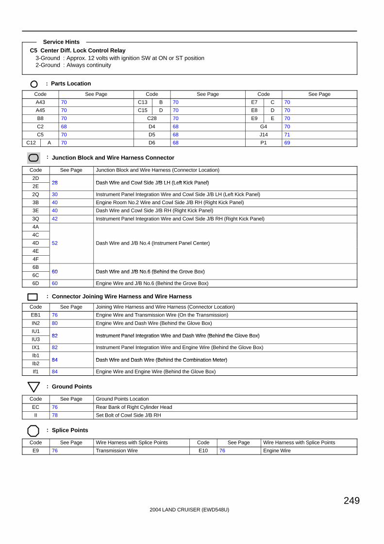
2004 LAND CRUISER (EWD548U)
249
C5 Center Diff. Lock Control Relay3-Ground : Approx. 12 volts with ignition SW at ON or ST position2-Ground : Always continuity
: Parts Location
Code See Page Code See Page Code See Page
A43 70 C13 B 70 E7 C 70
A45 70 C15 D 70 E8 D 70
B8 70 C28 70 E9 E 70
C2 68 D4 68 G4 70
C5 70 D5 68 J14 71
C12 A 70 D6 68 P1 69
: Junction Block and Wire Harness Connector
Code See Page Junction Block and Wire Harness (Connector Location)
2D28 Dash Wire and Cowl Side J/B LH (Left Kick Panel)
2E28 Dash Wire and Cowl Side J/B LH (Left Kick Panel)
2Q 30 Instrument Panel Integration Wire and Cowl Side J/B LH (Left Kick Panel)
3B 40 Engine Room No.2 Wire and Cowl Side J/B RH (Right Kick Panel)
3E 40 Dash Wire and Cowl Side J/B RH (Right Kick Panel)
3Q 42 Instrument Panel Integration Wire and Cowl Side J/B RH (Right Kick Panel)
4A
4C
4D 52 Dash Wire and J/B No.4 (Instrument Panel Center)
4E
( )
4F
6B60 Dash Wire and J/B No 6 (Behind the Grove Box)
6C60 Dash Wire and J/B No.6 (Behind the Grove Box)
6D 60 Engine Wire and J/B No.6 (Behind the Grove Box)
: Connector Joining Wire Harness and Wire Harness
Code See Page Joining Wire Harness and Wire Harness (Connector Location)
EB1 76 Engine Wire and Transmission Wire (On the Transmission)
IN2 80 Engine Wire and Dash Wire (Behind the Glove Box)
IU182 Instrument Panel Integration Wire and Dash Wire (Behind the Glove Box)
IU382 Instrument Panel Integration Wire and Dash Wire (Behind the Glove Box)
IX1 82 Instrument Panel Integration Wire and Engine Wire (Behind the Glove Box)
Ib184 Dash Wire and Dash Wire (Behind the Combination Meter)
Ib284 Dash Wire and Dash Wire (Behind the Combination Meter)
If1 84 Engine Wire and Engine Wire (Behind the Glove Box)
: Ground Points
Code See Page Ground Points Location
EC 76 Rear Bank of Right Cylinder Head
II 78 Set Bolt of Cowl Side J/B RH
: Splice Points
Code See Page Wire Harness with Splice Points Code See Page Wire Harness with Splice Points
E9 76 Transmission Wire E10 76 Engine Wire
Service Hints
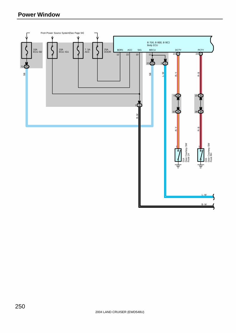
2004 LAND CRUISER (EWD548U)
250
Power Window
From Power Source System(See Page 94)
10AECU- IG1
B 7(A), B 8(B), B 9(C)
SIG7. 5AACC
25ADOOR
12 22
BDR1 ACC10AECU- B2
3Q712Q22 2I2
11
1 1
10 2K
8 2E
26 3K
15 3E
B23 B24
D14
D15
R-Y
R-B
R-Y
R-B
DCTY PCTY
SB
L-W
10
BECU
L- W
SB
Doo
r C
ourt
esy
SW
Fron
t LH
Doo
r C
ourt
esy
SW
Fron
t R
H
Body ECU
2I1
B- W
B-W

2004 LAND CRUISER (EWD548U)
251
B 7(A), B 8(B), B 9(C)
26 2K
W
Y-B
2J
1 6 3 4 5
DN UP LMT PLS SGND
EPLSLMTUD
1 4 2 3 5
G Y L-Y
L-W
BR
-B
10
Y-BW
W
P17
B16
IV49
BC411 BC410
MPX6
3J43K30
6
Y-B
Y-B
20AP/W(FL)
3E1
2E42
2I7
WLSW
P12L
L
B-WL-W
10 209
BDR SIGCPUB
8 11
PCTIMPX1
From Power Source System (See Page 94)
20AP/W(RR)
From Power Source System(See Page 94)
3K37
BC310
BK
7
GND
W-B
W-B
W-B
12
P20
BDR
3Q19 2Q74
Y- B
Y- B
L- W
LL
SB
Power WindowMaster SW
Power Window Motor Rear RH
Power Window ControlSW Rear RH
Body ECU
B- W
BC41
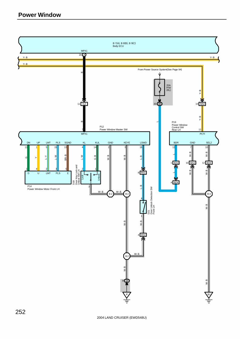
2004 LAND CRUISER (EWD548U)
252
Power Window
B 2 B 2
12
3
Lock
Unl
ock
P14
BR
-B
L-W
L-YYG
53241
D U LMT PLS E
SGNDPLSLMTUPDN
13155111
D18
4 14 2 3 16
KL
P12
MPX1
BB
MPX1
7
11 IC2
A24
KUL GND KEYE
L-W
LSWD
G-B
W-B
W-B
L-B
W- BW- B
W-B
BS18
1
4
L-B
IF
2I8
BS14
B 2
W-B
D21
W- B
W-B
B 7(A), B 8(B), B 9(C)
Y-B
Y-B
BA410
BA310 BA412
BJ
7 10
GND SEL2
W-B
W-B
W-B
BA31
BD44
20AP/W(RL)
From Power Source System(See Page 94)
3E33
L
BDR
12
LL
W-B
W-B
W-B
11
PCTI
P19
B 4
Y- B
Y- B
Y- B
Doo
r K
ey L
ock
and
Unl
ock
SW
LH
Doo
r U
nloc
k D
etec
tion
SW
Fro
nt L
H
Power Window Master SW
Power Window Motor Front LH
Power WindowControl SWRear LH
Body ECU
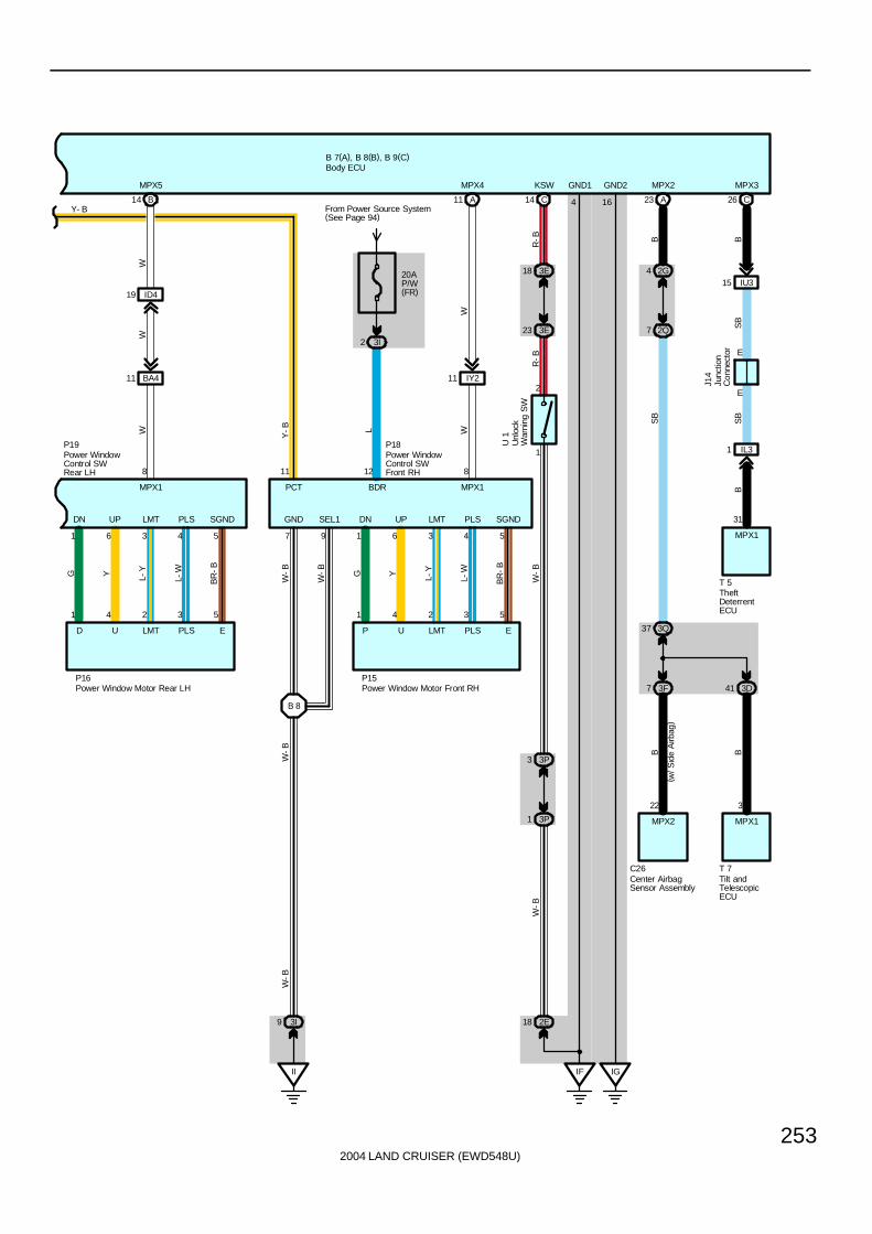
2004 LAND CRUISER (EWD548U)
253
E
E
IU315
C26
SB
B
MPX3
J14
( w/ S
ide
Airb
ag)
2G4
2Q7
23 A
3Q37
3F7 3D41
22
MPX2
C26
3
MPX1
T 7
B B
SB
B
MPX2
IF IG
4 16
GND1 GND2
T 5
31
SB
B
IL31
B 8
1 6 3 4 5
DN UP LMT PLS SGND
EPLSLMTUP
1 4 2 3 5
G Y L-Y
L-W
BR
-B
WW
P15
A11
IY211
MPX4
20AP/W(FR)
L
From Power Source System(See Page 94)
3I2
8
MPX1
12
BDR
11
PCT
GND
7
W-B
SEL1
9
W-B
P18
II
3I9
W-B
W-B
W
1 6 3 4 5
DN UP LMT PLS SGND
EPLSLMTUD
1 4 2 3 5
G Y L-Y
L-W
BR
-B
WW
P16
B14
ID419
BA411
MPX5
8
MPX1
B 7(A), B 8(B), B 9(C)
P19
Y- B
Y-B
MPX1
Center AirbagSensor Assembly
Power Window Motor Front RHPower Window Motor Rear LH
Power WindowControl SWFront RH
Power WindowControl SWRear LH
TheftDeterrentECU
Tilt andTelescopicECU
Body ECU
Junc
tion
Con
nect
or
KSW
R-B
R-B
C14
23 3E
18 3E
1
2
U 1
Unl
ock
War
ning
SW
1 3P
3 3P
18 2E
W-B
W-B
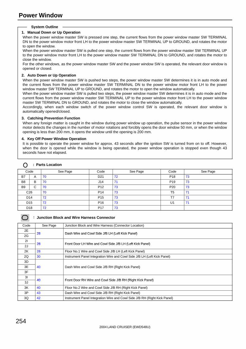
2004 LAND CRUISER (EWD548U)
254
Power Window
1. Manual Down or Up OperationWhen the power window master SW is pressed one step, the current flows from the power window master SW TERMINALDN to the power window motor front LH to the power window master SW TERMINAL UP to GROUND, and rotates the motorto open the window.When the power window master SW is pulled one step, the current flows from the power window master SW TERMINAL UPto the power window motor front LH to the power window master SW TERMINAL DN to GROUND, and rotates the motor toclose the window.For the other windows, as the power window master SW and the power window SW is operated, the relevant door window isopened or closed.
2. Auto Down or Up OperationWhen the power window master SW is pushed two steps, the power window master SW determines it is in auto mode andthe current flows from the power window master SW TERMINAL DN to the power window motor front LH to the powerwindow master SW TERMINAL UP to GROUND, and rotates the motor to open the window automatically.When the power window master SW is pulled two steps, the power window master SW determines it is in auto mode and thecurrent flows from the power window master SW TERMINAL UP to the power window motor front LH to the power windowmaster SW TERMINAL DN to GROUND, and rotates the motor to close the window automatically.Accordingly, when each window switch of the power window control SW is operated, the relevant door window isautomatically opened/closed.
3. Catching Prevention FunctionWhen any foreign matter is caught in the window during power window up operation, the pulse sensor in the power windowmotor detects the changes in the number of motor rotations and forcibly opens the door window 50 mm, or when the windowopening is less than 200 mm, it opens the window until the opening is 200 mm.
4. Key Off Power Window OperationIt is possible to operate the power window for approx. 43 seconds after the ignition SW is turned from on to off. However,when the door is opened while the window is being operated, the power window operation is stopped even though 43seconds have not elapsed.
: Parts Location
Code See Page Code See Page Code See Page
B7 A 70 D21 72 P18 73
B8 B 70 J14 71 P19 73
B9 C 70 P12 73 P20 73
C26 70 P14 73 T5 71
D14 72 P15 73 T7 71
D15 72 P16 73 U1 71
D18 72 P17 73
: Junction Block and Wire Harness Connector
Code See Page Junction Block and Wire Harness (Connector Location)
2E28 Dash Wire and Cowl Side J/B LH (Left Kick Panel)
2G28 Dash Wire and Cowl Side J/B LH (Left Kick Panel)
2I28 Front Door LH Wire and Cowl Side J/B LH (Left Kick Panel)
2J28 Front Door LH Wire and Cowl Side J/B LH (Left Kick Panel)
2K 28 Floor No.1 Wire and Cowl Side J/B LH (Left Kick Panel)
2Q 30 Instrument Panel Integration Wire and Cowl Side J/B LH (Left Kick Panel)
3D
3E 40 Dash Wire and Cowl Side J/B RH (Right Kick Panel)
3F
( g )
3I40 Front Door RH Wire and Cowl Side J/B RH (Right Kick Panel)
3J40 Front Door RH Wire and Cowl Side J/B RH (Right Kick Panel)
3K 40 Floor No.2 Wire and Cowl Side J/B RH (Right Kick Panel)
3P 43 Dash Wire and Cowl Side J/B RH (Right Kick Panel)
3Q 42 Instrument Panel Integration Wire and Cowl Side J/B RH (Right Kick Panel)
System Outline

2004 LAND CRUISER (EWD548U)
255
: Connector Joining Wire Harness and Wire Harness
Code See Page Joining Wire Harness and Wire Harness (Connector Location)
IC2 78 Front Door LH Wire and Dash Wire (Left Kick Panel)
ID4 78 Dash Wire and Floor No.1 Wire (Left Kick Panel)
IL3 80 Instrument Panel Integration Wire and Computer Wire (Instrument Panel Center)
IU3 82 Instrument Panel Integration Wire and Dash Wire (Behind the Glove Box)
IV4 82 Dash Wire and Floor No.2 Wire (Right Kick Panel)
IY2 82 Front Door RH Wire and Dash Wire (Right Kick Panel)
BA386 Rear Door LH Wire and Floor No 1 Wire (Left Side of Center Pillar)
BA486 Rear Door LH Wire and Floor No.1 Wire (Left Side of Center Pillar)
BC386 Rear Door RH Wire and Floor No 2 Wire (Right Side of Center Pillar)
BC486 Rear Door RH Wire and Floor No.2 Wire (Right Side of Center Pillar)
BD4 86 Floor No.3 Wire and Floor No.1 Wire (Left Rear Side Quarter Panel)
BS1 88 Door Lock LH Sub Wire and Front Door LH Wire (Front Door LH)
: Ground Points
Code See Page Ground Points Location
IF78 Set Bolt of Cowl Side J/B LH
IG78 Set Bolt of Cowl Side J/B LH
II 78 Set Bolt of Cowl Side J/B RH
BJ 86 Under the Driver’s Seat
BK 86 Front Side Under the Front Passenger’s Seat
: Splice Points
Code See Page Wire Harness with Splice Points Code See Page Wire Harness with Splice Points
B2 88 Front Door LH Wire B8 88 Front Door RH Wire
B4 88 Floor No.1 Wire
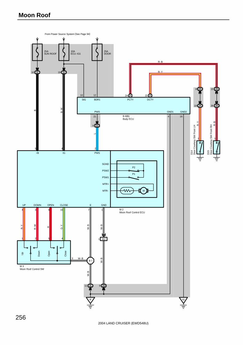
2004 LAND CRUISER (EWD548U)
256
Moon Roof
25ASUN ROOF
2L10
5
Dow
n
Up
Ope
n
Clo
se
P2
P1
1 2 5 4
4 3 9 10
R-Y
R-W R
G-Y
3
M 3
W- B
IF
B 7
2L11 2D9
IE21
7 1
M
10AECU- IG1
From Power Source System (See Page 94)
2L19
8
2L9
2
21
2K10 3K26
2E8 3E15
1 1
R-Y
R-B
L
B-WB
R- B
R- Y
M 2
D14
D15
W-B
W-B
W-B
W-B
UP DOWN OPEN CLOSE E GND
PWS
+B IG PWS
PCTY DCTY
SGND
PSW2
PSW1
MTR+
MTR-
Doo
r C
ourt
esy
SW
Fro
nt L
H
Doo
r C
ourt
esy
SW
Fro
nt R
HMoon Roof Control ECU
Moon Roof Control SW
25ADOOR
12
Body ECUB 8(B)
10
SIG BDR1
IG
GND1
4
B24 B23
GND2
16

2004 LAND CRUISER (EWD548U)
257
In this system, the HALL IC in the moon roof control ECU detects the changes in motor rotation, and allows opening/closing,tilting up/down of the moon roof by one touch operation.In addition, catching prevention function during moon roof operation is also provided.Voltage is constantly applied from the SUN ROOF fuse to the moon roof control ECU TERMINAL 5 of the moon roof controlECU.When the ignition SW is turned on, the current flows from the ECU-IG1 fuse to TERMINAL 8 of the moon roof control ECU.
1. Slide Open OperationWhen the moon roof control SW is kept pressed to OPEN position for approx. 0.3 seconds or longer (Limit SW No.1 off, limitSW No.2 on), a signal is input from the moon roof control SW TERMINAL 5 to the moon roof control ECU TERMINAL 9. Thisactivates the moon roof control ECU and rotates the motor to open the moon roof automatically. However, in case ofpressing the moon roof control SW for 0.3 seconds or less, the moon roof can be operated manually. Then, when the limitSW No.1 is turned on and then turned off again, the pulse signal sent from the HALL IC activates the moon roof control ECU,and determines that the moon roof is fully open, and stops the motor. If other operation SW or the open SW is operated whilethe moon roof is being opened, the moon roof control ECU is activated to stop the moon roof operation. In addition, when themoon roof is tilted up, the slide open operation does not function.
2. Slide Close OperationWhen the moon roof control SW is kept pressed to CLOSE position for approx. 0.3 seconds or longer (Limit SW No.1 off,limit SW No.2 off), a signal is input from the moon roof control SW TERMINAL 4 to the moon roof control ECU TERMINAL10. This activates the moon roof control ECU and rotates the motor to close the moon roof automatically. However, in case ofpressing the moon roof control SW for 0.3 seconds or less, the moon roof can be operated manually. Then, when the limitSW No.2 is turned on, the pulse signal sent from the HALL IC activates the moon roof control ECU, and determines that themoon roof is closed fully, and stops the motor. If other operation SW or the close SW is operated while the moon roof isbeing closed, the moon roof control ECU is activated to stop the moon roof operation.
3. Tilt Up OperationWhen the moon roof control SW is kept pressed to UP position for approx. 0.3 seconds or longer (Limit SW No.1 off, limit SWNo.2 on), a signal is input from the moon roof control SW TERMINAL 1 to the moon roof control ECU TERMINAL 4. Thisactivates the moon roof control ECU and rotates the motor to tilt up the moon roof automatically. If the pulse signal is notinput from the HALL IC for 0.5 seconds or longer, it determines that the moon roof is fully tilted up, and stops the motor. Ifother operation SW or the tilt up SW is operated while the moon roof is being tilted up, the moon roof control ECU isactivated to stop the moon roof operation. In addition, when the moon roof is opened, the tilt up operation does not function.
4. Tilt Down OperationWhen the moon roof control SW is kept pressed to DOWN position for approx. 0.3 seconds or longer (Limit SW No.1 on, limitSW No.2 on), a signal is input from the moon roof control SW TERMINAL 2 to the moon roof control ECU TERMINAL 3. Thisactivates the moon roof control ECU and rotates the motor to tilt down the moon roof automatically.Then, when the limit SW No.1 is turned off, the pulse signal sent from the HALL IC activated the moon roof control ECU, anddetermines that the moon roof is closed fully, and stops the motor.If other operation SW or the tilt down SW is operated while the moon roof is being tilted down, the moon roof control ECU isactivated to stop the moon roof operation.
5. Catching Prevention FunctionDuring slide close or tilt down operation, if the moon roof control ECU detects a catching load from the changes in therotation of the motor, the operation is stopped, and the motor is rotated in the reverse direction.∗ Slide close operation
The moon roof is moved approx. 200 mm in the reverse direction (Slide open) after a catching load has been detected.However, if the full open position is detected before moving approx. 200 mm, the reverse movement is stopped.
∗ Tilt down operationIf a catching load is detected, the moon roof is moved in the reverse direction until fully tilted up.
6. Key Off Moon Roof OperationWithin approx. 43 seconds after the ignition SW is turned from on to off, the moon roof can be operated. However, if thedriver or front passenger door is opened during this period of time, the moon roof operation is stopped even though 43seconds have not elapsed.
7. Fail-Safe FunctionIf the moon roof is operated continuously in the same direction, the current flowing to the motor is cut off when the timeshown below has elapsed after the motor operation has been started.∗ Slide open/close operation by the moon roof SW approx. 20 seconds∗ Tilt up/down operation by the moon roof SW approx. 2 second∗ Slide open operation for reverse movement in case of catching prevention function approx. 20 seconds∗ Tilt up operation for reverse movement in case of catching prevention function approx. 2 seconds
System Outline

2004 LAND CRUISER (EWD548U)
258
Moon Roof
: Parts Location
Code See Page Code See Page Code See Page
B8 B 70 D15 72 M3 72
D14 72 M2 72
: Junction Block and Wire Harness Connector
Code See Page Junction Block and Wire Harness (Connector Location)
2D28 Dash Wire and Cowl Side J/B LH (Left Kick Panel)
2E28 Dash Wire and Cowl Side J/B LH (Left Kick Panel)
2K 28 Floor No.1 Wire and Cowl Side J/B LH (Left Kick Panel)
2L 28 Roof No.1 Wire and Cowl Side J/B LH (Left Kick Panel)
3E 40 Dash Wire and Cowl Side J/B RH (Right Kick Panel)
3K 40 Floor No.2 Wire and Cowl Side J/B RH (Right Kick Panel)
: Connector Joining Wire Harness and Wire Harness
Code See Page Joining Wire Harness and Wire Harness (Connector Location)
IE2 78 Dash Wire and Roof No.1 Wire (Left Kick Panel)
: Ground Points
Code See Page Ground Points Location
IF78 Set Bolt of Cowl Side J/B LH
IG78 Set Bolt of Cowl Side J/B LH
: Splice Points
Code See Page Wire Harness with Splice Points Code See Page Wire Harness with Splice Points
B7 88 Roof No.1 Wire

2004 LAND CRUISER (EWD548U)
259
Memo
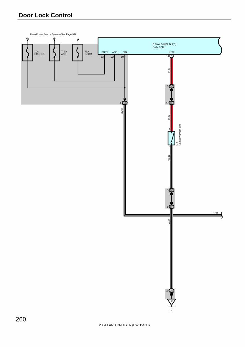
2004 LAND CRUISER (EWD548U)
260
Door Lock Control
From Power Source System (See Page 94)
B 7(A), B 8(B), B 9(C)
12 22
BDR1 ACC
10
SIG10AECU- IG1
7. 5AACC
25ADOOR
14
KSW
C
1
2
1 3P
3 3P
U 1
W-B
W-B
IF
2E18
23 3E
18 3E
R-B
R-B
Unl
ock
War
ning
SW
Body ECU
B- W
2I1
B-W

2004 LAND CRUISER (EWD548U)
261
B 7(A), B 8(B), B 9(C)
L
BDR
10W
-B
W- B W- B
L-B
W-B
W-B
G-B
LSWD
L-W
KEYEGNDKUL
24 A
IC211
7
MPX1
BB
MPX1
P12
20AP/W(FL)
From Power Source System (See Page 94)
3E1
2E42
2I7
KL
1632144
D18
L
Unl
ock
Lock
3
2 1
B 2
2I8
IF
B 2B 2
W-B
71 3Q
10AECU- B2
2 2I
22 2QS
B
9
CPUB
L-W
W- B
L- B
11
BECU
Doo
r K
ey L
ock
and
Unl
ock
SW
LH
Power Window Master SW
Body ECU
B- W
20
SIG
B-W

2004 LAND CRUISER (EWD548U)
262
Door Lock Control
B 7(A), B 8(B), B 9(C)
W- B
BC414
BC38 BC39
3K5 3K34 3I5
3E42
3I3 3E39
BC413
BL52
BD49
4 2 3
1
V L-B
V L-B
W-B
W-B
V V L-B
GR
-LG
R-L
GR- L
D24
GR- L
L- B
V
V
L- B
L-B
GR
-L
BK
L- B
W- B
L- B
Door Lock Motor Rear RHDoor Unlock DetectionSW Rear RH
Body ECUS
BS
B
J14
70 2Q
C15
B
16
B
SPD
14
Combination Meter
JunctionConnector
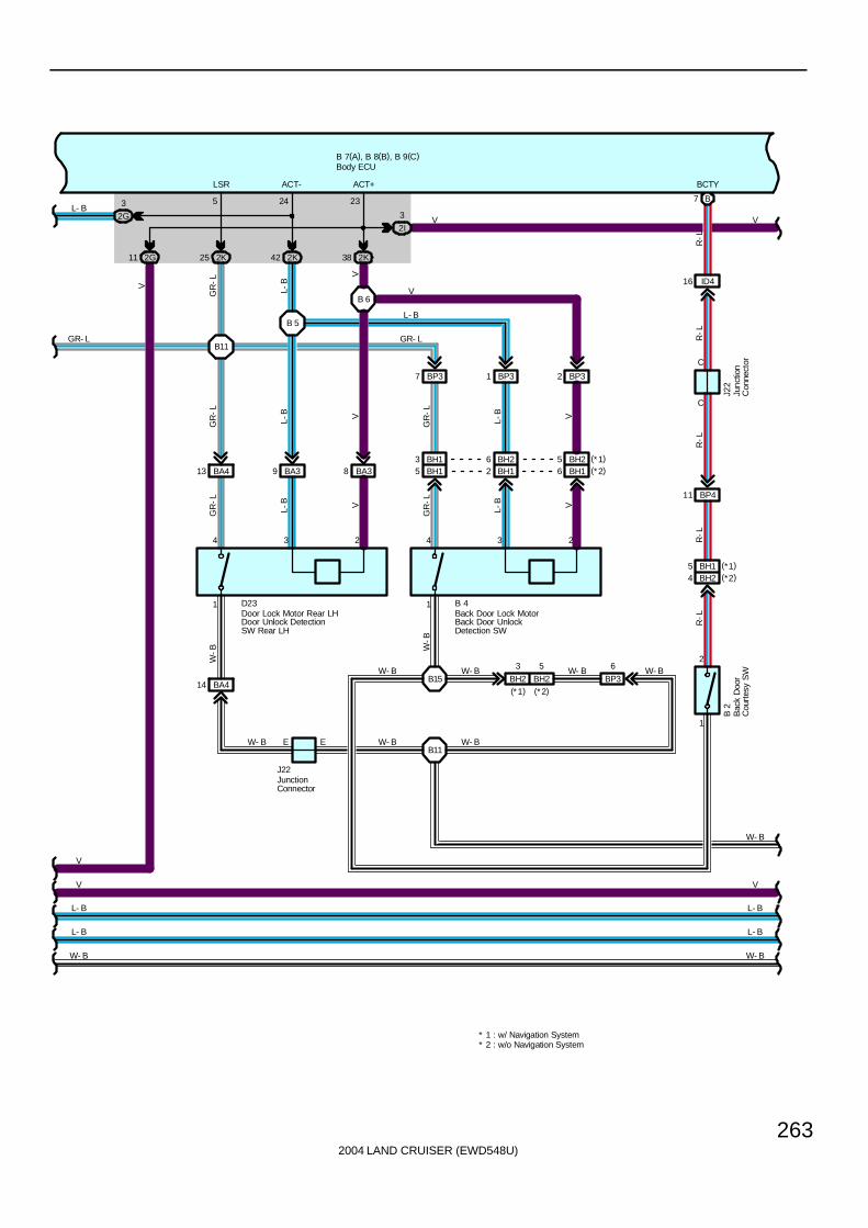
2004 LAND CRUISER (EWD548U)
263
B 7(A), B 8(B), B 9(C)
L- B
W- B
D23
W- B
2G11
BA4
BA39 BA38
4 3 2
1
L-B V
W-B
5
BH2
4 3 2
1
L-B V
W-B
BA413
2K25 2K42 2K38
BP37 BP31 BP32
GR
-L
L-B V
GR
-L
L-B V
GR
-L
GR
-L
V
L-B
GR
-LV
V
L- B
GR- LGR- L
L- B
6
BP3
V
V
2G
3
LSR ACT- ACT+
5 24 23
E
14
J22
L- B
V
W- B W- B W- B
W- B
W- B
B 4
B15
B11W- B E
B11
B 5
B 6
2I
3 VV
L- B
W- B
L- B
W- B
Back Door Lock MotorBack Door UnlockDetection SW
Door Lock Motor Rear LHDoor Unlock DetectionSW Rear LH
Body ECU
JunctionConnector
BH15 BH12 BH16
1
2
ID416
B7
C
C
BP411
BH24
J22
B 2
R-L
R-L
R-L
R-L
R-L
BCTY
Bac
k D
oor
Cou
rtes
y S
WJu
nctio
nC
onne
ctor
BH13 BH26 BH25 (*1)(*2)
BH15 (*1)(*2)
BH2
3
(*1) (*2)
* 2 : w/o Navigation System* 1 : w/ Navigation System
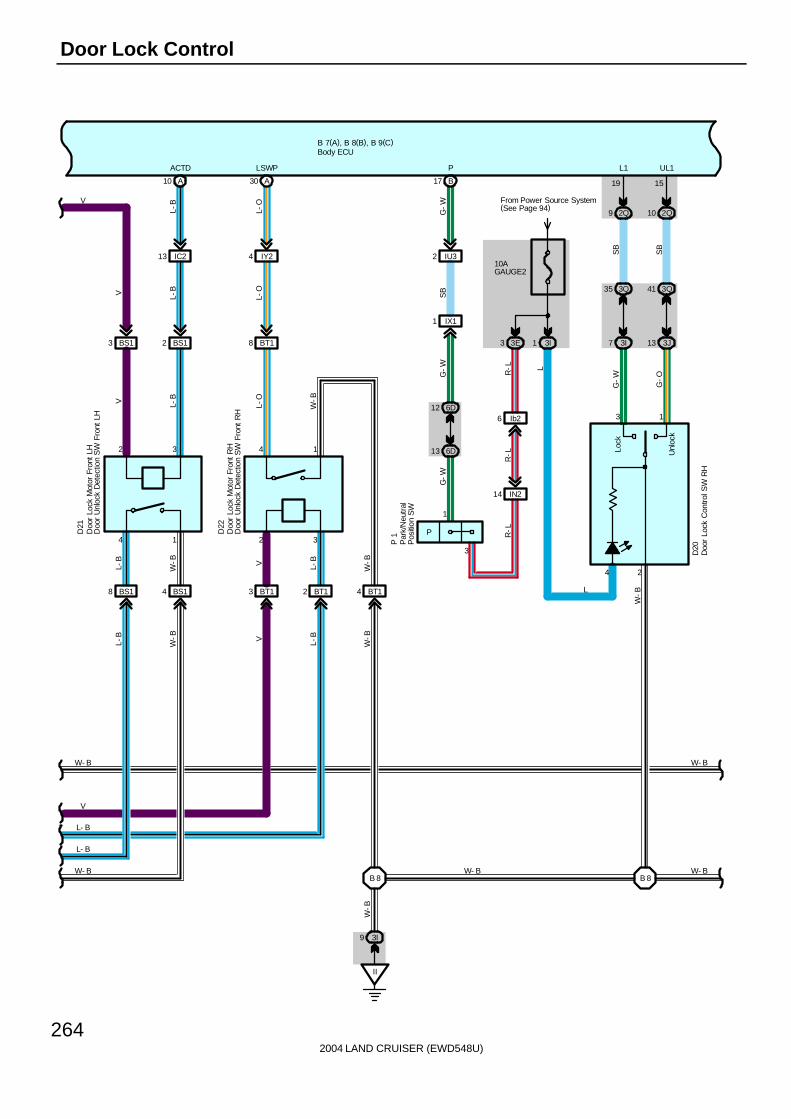
2004 LAND CRUISER (EWD548U)
264
Door Lock Control
B 7(A), B 8(B), B 9(C)
BS18 BS14 BT13 BT12 BT14
BS13 BS12 BT18
IY24IC213
A10 A30
ACTD LSWP
4 1 2 3
432
D21
V L-B
L-O
L-B
L-O
V L-B
L-O
L-B
W-B
W-B
L-B V L-B
W-B
W-B
W- B W- BB 8 B 8
V
W- B
L- B
W- B
V
L- B
L-B V
II
3I9
W-B
W- B
Doo
r Lo
ck M
otor
Fro
nt L
HD
oor
Unl
ock
Det
ectio
n S
W F
ront
LH
Doo
r Lo
ck M
otor
Fro
nt R
HD
oor
Unl
ock
Det
ectio
n S
W F
ront
RH
Body ECU
W-B
1
D22
Unl
ock
Lock
3 1
3Q35
3I7 3J13
2Q9 2Q10
3Q41
10AGAUGE2
From Power Source System(See Page 94)
3I1
4
19 15
L1 UL1
L
G-W
G-O
SB
SB
W-BL
2
D20
3E3
R-L
Doo
r Lo
ck C
ontro
l SW
RH
6 Ib2
IN214
R-L
R-LP
1
3
13 6D
6D12
IX11
IU32
B17
G-W
SB
G-W
G-W
P
Par
k/N
eutr
alP
ositi
on S
W
P 1

2004 LAND CRUISER (EWD548U)
265
B 7(A), B 8(B), B 9(C)
21
3
Unl
ock
Lock
Lock
Unl
ock
1
3 2
BQ22 BQ210
24 2K
12 2Q
14 3J
40 3E
42 3Q
3I8 3Q30
2K292Q11
A22
1 1 1 1
10 2K
8 2E
26 3K
15 3E
B23 B24 B11 B12
ID415 IV37
D14
D15
D16
D17
D19
B 3
W- B
G-B
SB
G-B
L-W
G-B
W-B
G-B
W-B
R-Y
R-B
R-L
R-G
R-Y
R-B
R-L
R-G
G-B
W-B
L-W
SB
G- B
UL2 L2 DCTY RLCY RRCY
20
BQ21
L-W
PCTY
BJ
W-B
B11W- B
Bac
k D
oor
Key
Loc
k an
dU
nloc
k S
W
Doo
r C
ourt
esy
SW
Fro
nt L
H
Doo
r C
ourt
esy
SW
Fro
nt R
H
Doo
r C
ourt
esy
SW
Rea
r LH
Doo
r C
ourt
esy
SW
Rea
r R
H
Doo
r K
ey L
ock
and
Unl
ock
SW
RH
Body ECU
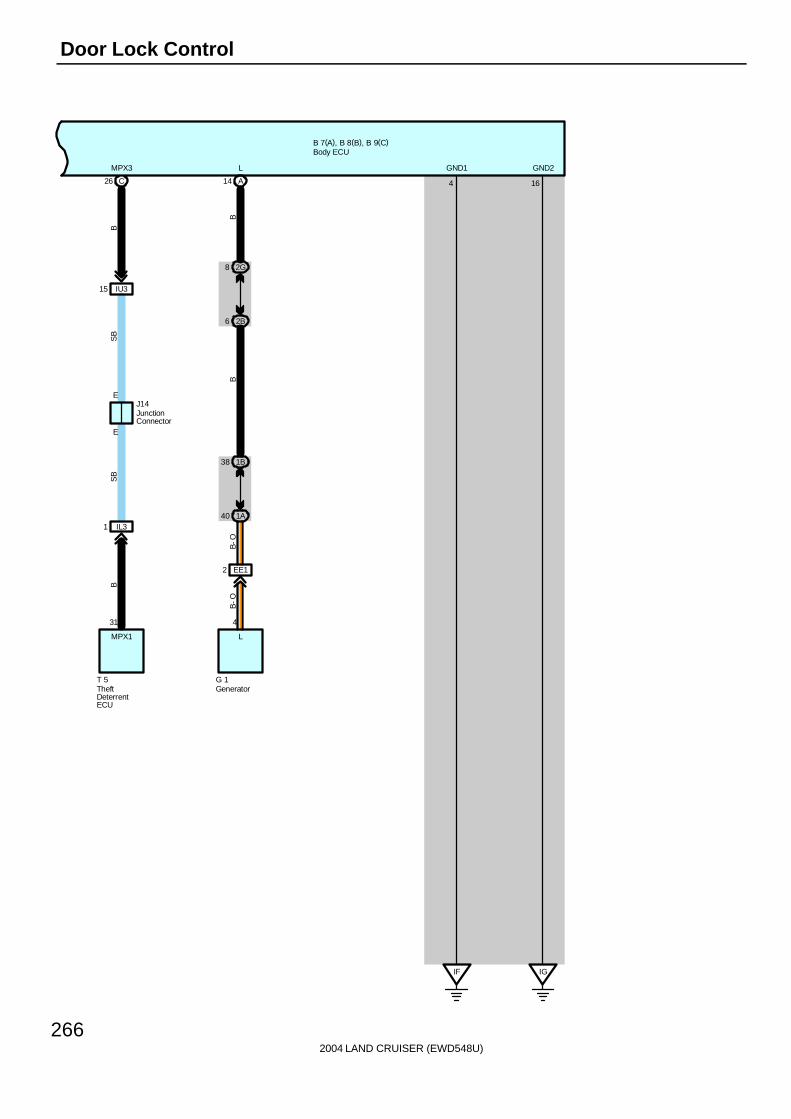
2004 LAND CRUISER (EWD548U)
266
Door Lock Control
B 7(A), B 8(B), B 9(C)
EJ14
2G8
2B6
14 A
1B38
1A40
4
L
G 1
IF IG
B-O
BB
4 16
L GND1 GND2MPX3
B
31
MPX1
T 5
E
C26
IU315
IL31
SB
SB
B
GeneratorTheftDeterrentECU
Body ECU
JunctionConnector
EE12
B-O
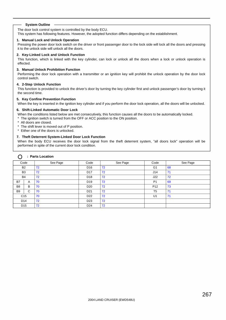
2004 LAND CRUISER (EWD548U)
267
The door lock control system is controlled by the body ECU.This system has following features. However, the adopted function differs depending on the establishment.
1. Manual Lock and Unlock OperationPressing the power door lock switch on the driver or front passenger door to the lock side will lock all the doors and pressingit to the unlock side will unlock all the doors.
2. Key-Linked Lock and Unlock FunctionThis function, which is linked with the key cylinder, can lock or unlock all the doors when a lock or unlock operation iseffected.
3. Manual Unlock Prohibition FunctionPerforming the door lock operation with a transmitter or an ignition key will prohibit the unlock operation by the door lockcontrol switch.
4. 2-Step Unlock FunctionThis function is provided to unlock the driver’s door by turning the key cylinder first and unlock passenger’s door by turning itthe second time.
5. Key Confine Prevention FunctionWhen the key is inserted in the ignition key cylinder and if you perform the door lock operation, all the doors will be unlocked.
6. Shift-Linked Automatic Door LockWhen the conditions listed below are met consecutively, this function causes all the doors to be automatically locked.∗ The ignition switch is turned from the OFF or ACC position to the ON position.∗ All doors are closed.∗ The shift lever is moved out of P position.∗ Either one of the doors is unlocked.
7. Theft Deterrent System-Linked Door Lock FunctionWhen the body ECU receives the door lock signal from the theft deterrent system, ”all doors lock” operation will beperformed in spite of the current door lock condition.
: Parts Location
Code See Page Code See Page Code See Page
B2 72 D16 72 G1 68
B3 72 D17 72 J14 71
B4 72 D18 72 J22 72
B7 A 70 D19 72 P1 69
B8 B 70 D20 72 P12 73
B9 C 70 D21 72 T5 71
C15 70 D22 72 U1 71
D14 72 D23 72
D15 72 D24 72
System Outline

2004 LAND CRUISER (EWD548U)
268
Door Lock Control
: Junction Block and Wire Harness Connector
Code See Page Junction Block and Wire Harness (Connector Location)
1A 24 Engine Room Main Wire and Engine Room J/B (Engine Compartment Left)
1B 24 Engine Room No.2 Wire and Engine Room J/B (Engine Compartment Left)
2B 28 Engine Room No.2 Wire and Cowl Side J/B LH (Left Kick Panel)
2E28 Dash Wire and Cowl Side J/B LH (Left Kick Panel)
2G28 Dash Wire and Cowl Side J/B LH (Left Kick Panel)
2I 28 Front Door LH Wire and Cowl Side J/B LH (Left Kick Panel)
2K 28 Floor No.1 Wire and Cowl Side J/B LH (Left Kick Panel)
2Q 30 Instrument Panel Integration Wire and Cowl Side J/B LH (Left Kick Panel)
3E 40 Dash Wire and Cowl Side J/B RH (Right Kick Panel)
3I40 Front Door RH Wire and Cowl Side J/B RH (Right Kick Panel)
3J40 Front Door RH Wire and Cowl Side J/B RH (Right Kick Panel)
3K 40 Floor No.2 Wire and Cowl Side J/B RH (Right Kick Panel)
3P 43 Dash Wire and Cowl Side J/B RH (Right Kick Panel)
3Q 42 Instrument Panel Integration Wire and Cowl Side J/B RH (Right Kick Panel)
6D 60 Engine Wire and J/B No.6 (Behind the Grove Box)
: Connector Joining Wire Harness and Wire Harness
Code See Page Joining Wire Harness and Wire Harness (Connector Location)
EE1 76 Engine Room Main Wire and Alternator Wire (Near the Battery)
IC2 78 Front Door LH Wire and Dash Wire (Left Kick Panel)
ID4 78 Dash Wire and Floor No.1 Wire (Left Kick Panel)
IL3 80 Instrument Panel Integration Wire and Computer Wire (Instrument Panel Center)
IN2 80 Engine Wire and Dash Wire (Behind the Glove Box)
IU3 82 Instrument Panel Integration Wire and Dash Wire (Behind the Glove Box)
IV3 82 Dash Wire and Floor No.2 Wire (Right Kick Panel)
IX1 82 Instrument Panel Integration Wire and Engine Wire (Behind the Glove Box)
IY2 82 Front Door RH Wire and Dash Wire (Right Kick Panel)
Ib2 84 Dash Wire and Dash Wire (Behind the Combination Meter)
BA386 Rear Door LH Wire and Floor No 1 Wire (Left Side of Center Pillar)
BA486 Rear Door LH Wire and Floor No.1 Wire (Left Side of Center Pillar)
BC386 Rear Door RH Wire and Floor No 2 Wire (Right Side of Center Pillar)
BC486 Rear Door RH Wire and Floor No.2 Wire (Right Side of Center Pillar)
BD4 86 Floor No.3 Wire and Floor No.1 Wire (Left Rear Side Quarter Panel)
BH186 Pillar No 1 Wire and Back Door Upper Wire (Left Side of Back Door)
BH286 Pillar No.1 Wire and Back Door Upper Wire (Left Side of Back Door)
BL5 88 Floor No.2 Wire and Floor No.3 Wire (Right Side of Rear Floor Crossmember)
BP388 Pillar No 1 Wire and Floor No 1 Wire (Left Rear Side Quarter Panel)
BP488 Pillar No.1 Wire and Floor No.1 Wire (Left Rear Side Quarter Panel)
BQ2 88 Back Door Lower Wire and Floor No.1 Wire (Left Rear Side Quarter Panel)
BS1 88 Door Lock LH Sub Wire and Front Door LH Wire (Front Door LH)
BT1 88 Door Lock RH Sub Wire and Front Door RH Wire (Front Door RH)
: Ground Points
Code See Page Ground Points Location
IF78 Set Bolt of Cowl Side J/B LH
IG78 Set Bolt of Cowl Side J/B LH
II 78 Set Bolt of Cowl Side J/B RH
BJ 86 Under the Driver’s Seat
BK 86 Front Side Under the Front Passenger’s Seat

2004 LAND CRUISER (EWD548U)
269
: Splice Points
Code See Page Wire Harness with Splice Points Code See Page Wire Harness with Splice Points
B2 88 Front Door LH Wire B8 88 Front Door RH Wire
B588 Floor No 1 Wire
B11 88 Floor No.1 Wire
B688 Floor No.1 Wire
B15 88 Back Door Upper Wire

2004 LAND CRUISER (EWD548U)
270
Wireless Door Lock Control
From Power Source System (See Page 94)
B 7(A), B 8(B), B 9(C)
12 22
BDR1 ACC
10
SIG10AECU- IG1
7. 5AACC
25ADOOR
14
KSW
C
1
2
1 3P
3 3P
U 1
W-B
W-B
23 3E
18 3E
R-B
R-B
Unl
ock
War
ning
SW
Body ECU
B- W
W- B
B-W
2I1

2004 LAND CRUISER (EWD548U)
271
B 7(A), B 8(B), B 9(C)L
BDR
10
W-B
W- B W- B
L-B
W-B
W-B
G-B
LSWD
L-W
KEYEGNDKUL
24 A
IC211
7
MPX1
BB
MPX1
P12
20AP/W(FL)
From Power Source System (See Page 94)
3E1
2E42
2I7
KL
1632144
D18
L
Unl
ock
Lock
3
2 1
B 2
2I8
IF
B 2B 2
W-B
71 3Q
10AECU- B2
2 2I
22 2Q
SB
9
CPUB
L-W
W- B
L- B
11
BECU
Doo
r K
ey L
ock
and
Unl
ock
SW
LH
Power Window Master SW
Body ECU
B- W
20
SIG
B-W
2E18
W- B
W-B

2004 LAND CRUISER (EWD548U)
272
Wireless Door Lock Control
B 7(A), B 8(B), B 9(C)
W- B
BC414
BC38 BC39
3K5 3K34 3I5
3E42
3I3 3E39
BC413
BL52
BD49
4 2 3
1
V L-B
V L-B
W-B
W-B
V V L-B
GR
-LG
R-L
GR- L
D24
GR- L
L- B
V
V
L- B
L-B
GR
-L
BK
SB
J14
70 2Q
C15
B
16
B
SPD
14
SB
L- B
W- B
L- B
Combination Meter
Door Lock Motor Rear RHDoor Unlock DetectionSW Rear RH
Body ECU
JunctionConnector
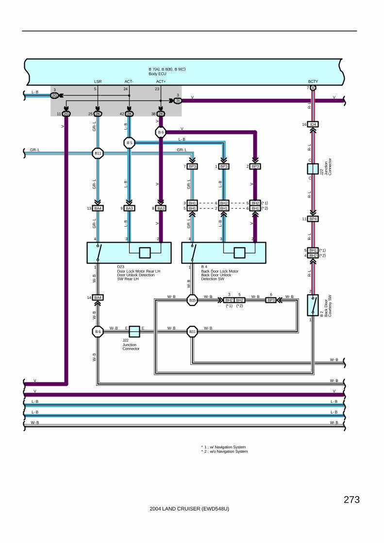
2004 LAND CRUISER (EWD548U)
273
B 7(A), B 8(B), B 9(C)
L- B
W- B
D23
W- B
2G11
BA4
BA39 BA38
4 3 2
1
L-B V
W-B
5
BH2
4 3 2
1
L-B V
W-B
BA413
2K25 2K42 2K38
BP37 BP31 BP32
GR
-L
L-B V
GR
-L
L-B V
GR
-L
GR
-L
V
L-B
GR
-LV
V
L- B
GR- LGR- L
L- B
6
BP3
V
V
2G
3
LSR ACT- ACT+
5 24 23
E
14
J22
L- B
V
W- B W- B W- B
W- B
W- B
B 4
B15
B11W- B E
B11
B 5
B 6
2I
3 VV
L- B
W- B
L- B
W- B
B 6
W-B
W-B
W- B
Back Door Lock MotorBack Door UnlockDetection SW
Door Lock Motor Rear LHDoor Unlock DetectionSW Rear LH
Body ECU
JunctionConnector
BH15 BH12 BH16
1
2
ID416
B7
C
C
BP411
BH24
J22
B 2
R-L
R-L
R-L
R-L
R-L
BCTY
Bac
k D
oor
Cou
rtes
y S
WJu
nctio
nC
onne
ctor
BH25 (*1)(*2)
BH26BH13
BH15 (*1)(*2)
BH2
3
(*1) (*2)
* 2 : w/o Navigation System* 1 : w/ Navigation System

2004 LAND CRUISER (EWD548U)
274
Wireless Door Lock Control
B 7(A), B 8(B), B 9(C)
BS18 BS14 BT13 BT12 BT14
BS13 BS12 BT18
IY24IC213
A10 A30
ACTD LSWP
4 1 2 3
432
D21
D22
V L-B
L-O
L-B
L-O
V L-B
L-O
L-B
W-B
W-B
L-B V L-B
W-B
W-B
W- B W- BB 8 B 8
V
W- B
L- B
W- B
V
L- B
L-B V
II
3I9
W-B
W- B
W- B W- BW- B
Doo
r Lo
ck M
otor
Fro
nt L
HD
oor
Unl
ock
Det
ectio
n S
W F
ront
LH
Doo
r Lo
ck M
otor
Fro
nt R
HD
oor
Unl
ock
Det
ectio
n S
W F
ront
RH
Body ECU
1
W- B
Unl
ock
Lock
3 1
3Q35
3I7 3J13
2Q9 2Q10
3Q41
10AGAUGE2
From Power Source System(See Page 94)
3I1
4
19 15
L1 UL1
L
G-W
G-O
SB
SB
W-BL
2
D20
3E3
R-L
Doo
r Lo
ck C
ontro
l SW
RH
6 Ib2
IN214R
-LR
-LP
1
3
13 6D
6D12
IX11
IU32
B17
G-W
SB
G-W
G-W
P
Par
k/N
eutr
alP
ositi
on S
W
P 1

2004 LAND CRUISER (EWD548U)
275
B 7(A), B 8(B), B 9(C)
21
3
Unl
ock
Lock
Lock
Unl
ock
1
3 2
BQ22 BQ210
24 2K
12 2Q
14 3J
40 3E
42 3Q
3I8 3Q30
2K292Q11
A22
1 1 1 1
10 2K
8 2E
26 3K
15 3E
B23 B24 B11 B12
ID415 IV37
D14
D15
D16
D17
D19
B 3
W- B
G-B
SB
G-B
L-W
G-B
W-B
G-B
W-B
R-Y
R-B
R-L
R-G
R-Y
R-B
R-L
R-G
G-B
W-B
L-W
SB
G- B
UL2 L2 DCTY RLCY RRCY
20
BQ21
L-W
PCTY
BJ
W-B
B11W- B
W- B W- BW- B
Bac
k D
oor
Key
Loc
kan
d U
nloc
k S
W
Doo
r C
ourt
esy
SW
Fro
nt L
H
Doo
r C
ourt
esy
SW
Fro
nt R
H
Doo
r C
ourt
esy
SW
Rea
r LH
Doo
r C
ourt
esy
SW
Rea
r R
H
Doo
r K
ey L
ock
and
Unl
ock
SW
RH
Body ECU

2004 LAND CRUISER (EWD548U)
276
Wireless Door Lock Control
B 7(A), B 8(B), B 9(C)
3 A
DO
ME
Rel
ay
1 5
2 3
2G1
2K9 2Q79
R-W
L-Y
LMRY
SB
10ADOME
3Q17
From Power Source System (See Page 94)
BP41BP49
BP48BP43
ID417ID418
B4B3
D27
L-Y
W-B
LV
LV
LV
L-Y
W-B
RDAPRG
51
23
W- B
Body ECU
Doo
r C
ontr
ol R
ecei
ver
PRG RDA
E +B

2004 LAND CRUISER (EWD548U)
277
EJ14
2G8
2B6
14 A
1B38
1A40
4
L
G 1
IF IG
B-O
BB
4 16
L GND1 GND2MPX3
B
31
MPX1
E
C26
IU315
IL31
SB
SB
B
B 7(A), B 8(B), B 9(C)
T 5Generator Theft
DeterrentECU
Body ECU
JunctionConnector
EE12
B-O
2004 LAND CRUISER (EWD548U)
278
Wireless Door Lock Control
In this system, the door control receiver receivers weak radio wave transmitted from the transmitter built-into the ignition key,and outputs a signal to the body ECU. Accordingly, all the doors are can be locked and unlocked by remote control.
1. Normal Operation∗ Lock operation
When the lock SW on the transmitter is pressed, all the doors are locked.∗ Unlock operation
When the unlock SW on the transmitter is pressed once, only the driver door is unlocked. When the unlock SW is pressedagain within 3 seconds, all the doors are unlocked.
2. Auto Lock FunctionWhen the door is not actually opened within 30 seconds after the door has been unlocked by the unlock SW on thetransmitter, all the doors are automatically locked. If any of the following conditions are detected, the wireless door lock doesnot function.∗ Any door is opened.∗ The ignition key is inserted into the ignition SW.∗ When the unlock detection SW of all the doors are locked.
3. Wireless Door Lock Stop FunctionIf any of the following conditions are detected, the wireless door lock does not function.Lock operation∗ When any door is open (Door courtesy SW on)∗ The ignition key is inserted into the ignition SW (Unlock warning SW on)∗ Ignition SW is onUnlock operation∗ Ignition SW is on
4. Visual Confirmation of Lock or UnlockDuring lock operation, when the door control receiver receives a lock signal from the door unlock detection SW, the turnsignal light is flashed once. During unlock operation, when the door control receiver receives an unlock signal from the doorunlock detection SW, the turn signal light is flashed twice.
5. Panic Mode FunctionWhen the panic SW on the transmitter is pressed, the door control receiver receives a signal and enters the panic mode.The signal input into the theft deterrent ECU from the body ECU turns on the theft deterrent horn, and flashes the taillightand headlight. When the panic SW or the unlock SW of the transmitter is pressed during the panic mode, the panic mode iscanceled, and the theft deterrent horn stops, and the taillight and headlight are turned off.
6. Repeat FunctionIf the lock detection signal in response to the output signal is not received after the door control receiver has output the locksignal, the lock signal is output again.
D27 Door Control Receiver5-Ground : Always approx. 12 volts1-Ground : Always continuity
D21, D22, D23, D24 Door Unlock Detection SW Front LH, RH, Rear LH, RH1-Ground : Always continuity
B4 Back Door Unlock Detection SW1-Ground : Always continuity
System Outline
Service Hints
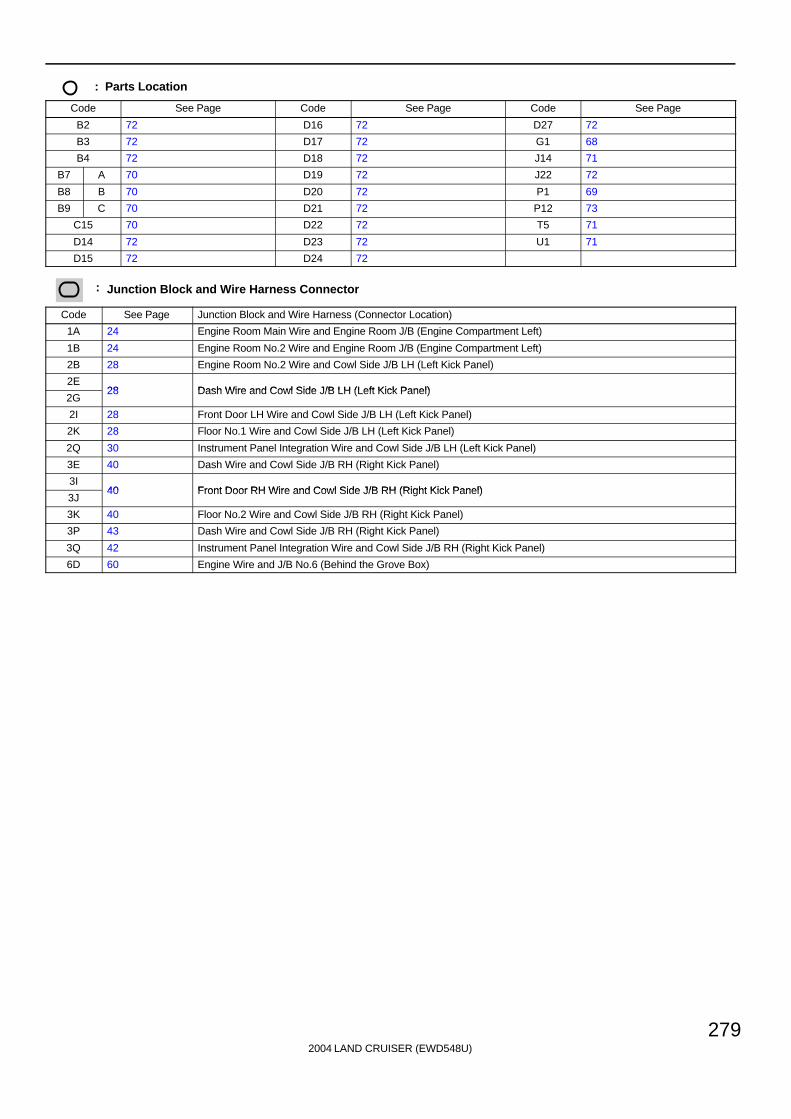
2004 LAND CRUISER (EWD548U)
279
: Parts Location
Code See Page Code See Page Code See Page
B2 72 D16 72 D27 72
B3 72 D17 72 G1 68
B4 72 D18 72 J14 71
B7 A 70 D19 72 J22 72
B8 B 70 D20 72 P1 69
B9 C 70 D21 72 P12 73
C15 70 D22 72 T5 71
D14 72 D23 72 U1 71
D15 72 D24 72
: Junction Block and Wire Harness Connector
Code See Page Junction Block and Wire Harness (Connector Location)
1A 24 Engine Room Main Wire and Engine Room J/B (Engine Compartment Left)
1B 24 Engine Room No.2 Wire and Engine Room J/B (Engine Compartment Left)
2B 28 Engine Room No.2 Wire and Cowl Side J/B LH (Left Kick Panel)
2E28 Dash Wire and Cowl Side J/B LH (Left Kick Panel)
2G28 Dash Wire and Cowl Side J/B LH (Left Kick Panel)
2I 28 Front Door LH Wire and Cowl Side J/B LH (Left Kick Panel)
2K 28 Floor No.1 Wire and Cowl Side J/B LH (Left Kick Panel)
2Q 30 Instrument Panel Integration Wire and Cowl Side J/B LH (Left Kick Panel)
3E 40 Dash Wire and Cowl Side J/B RH (Right Kick Panel)
3I40 Front Door RH Wire and Cowl Side J/B RH (Right Kick Panel)
3J40 Front Door RH Wire and Cowl Side J/B RH (Right Kick Panel)
3K 40 Floor No.2 Wire and Cowl Side J/B RH (Right Kick Panel)
3P 43 Dash Wire and Cowl Side J/B RH (Right Kick Panel)
3Q 42 Instrument Panel Integration Wire and Cowl Side J/B RH (Right Kick Panel)
6D 60 Engine Wire and J/B No.6 (Behind the Grove Box)

2004 LAND CRUISER (EWD548U)
280
Wireless Door Lock Control
: Connector Joining Wire Harness and Wire Harness
Code See Page Joining Wire Harness and Wire Harness (Connector Location)
EE1 76 Engine Room Main Wire and Alternator Wire (Near the Battery)
IC2 78 Front Door LH Wire and Dash Wire (Left Kick Panel)
ID4 78 Dash Wire and Floor No.1 Wire (Left Kick Panel)
IL3 80 Instrument Panel Integration Wire and Computer Wire (Instrument Panel Center)
IN2 80 Engine Wire and Dash Wire (Behind the Glove Box)
IU3 82 Instrument Panel Integration Wire and Dash Wire (Behind the Glove Box)
IV3 82 Dash Wire and Floor No.2 Wire (Right Kick Panel)
IX1 82 Instrument Panel Integration Wire and Engine Wire (Behind the Glove Box)
IY2 82 Front Door RH Wire and Dash Wire (Right Kick Panel)
Ib2 84 Dash Wire and Dash Wire (Behind the Combination Meter)
BA386 Rear Door LH Wire and Floor No 1 Wire (Left Side of Center Pillar)
BA486 Rear Door LH Wire and Floor No.1 Wire (Left Side of Center Pillar)
BC386 Rear Door RH Wire and Floor No 2 Wire (Right Side of Center Pillar)
BC486 Rear Door RH Wire and Floor No.2 Wire (Right Side of Center Pillar)
BD4 86 Floor No.3 Wire and Floor No.1 Wire (Left Rear Side Quarter Panel)
BH186 Pillar No 1 Wire and Back Door Upper Wire (Left Side of Back Door)
BH286 Pillar No.1 Wire and Back Door Upper Wire (Left Side of Back Door)
BL5 88 Floor No.2 Wire and Floor No.3 Wire (Right Side of Rear Floor Crossmember)
BP388 Pillar No 1 Wire and Floor No 1 Wire (Left Rear Side Quarter Panel)
BP488 Pillar No.1 Wire and Floor No.1 Wire (Left Rear Side Quarter Panel)
BQ2 88 Back Door Lower Wire and Floor No.1 Wire (Left Rear Side Quarter Panel)
BS1 88 Door Lock LH Sub Wire and Front Door LH Wire (Front Door LH)
BT1 88 Door Lock RH Sub Wire and Front Door RH Wire (Front Door RH)
: Ground Points
Code See Page Ground Points Location
IF78 Set Bolt of Cowl Side J/B LH
IG78 Set Bolt of Cowl Side J/B LH
II 78 Set Bolt of Cowl Side J/B RH
BJ 86 Under the Driver’s Seat
BK 86 Front Side Under the Front Passenger’s Seat
: Splice Points
Code See Page Wire Harness with Splice Points Code See Page Wire Harness with Splice Points
B2 88 Front Door LH Wire B8 88 Front Door RH Wire
B588 Floor No 1 Wire
B11 88 Floor No.1 Wire
B688 Floor No.1 Wire
B15 88 Back Door Upper Wire

2004 LAND CRUISER (EWD548U)
281
Memo

2004 LAND CRUISER (EWD548U)
282
Theft Deterrent
120AJ/BNO. 1
140AALT
B 7(A), B 8(B), B 9(C)
Battery
1
B-G
G-B
GG
TRLYIDL
5B4
5D3
2B24
A28 18
2 1C
TAIL
Rel
ay
1B49
15ATAIL
1B67
Body ECU
Fusi
ble
Link
Blo
ckF1
5 SB
B- W
25ADOOR
7. 5AACC
From Power Source System (See Page 94)
10
SIG
12 22
BDR1 ACC
2I1
B-W
2Q21
SB
10AECU- IG1

2004 LAND CRUISER (EWD548U)
283
B 7(A), B 8(B), B 9(C)
T 5
C
C
24 2Q
9 2B
21 1B
W-B
L- W
V- W
B
G-R
SB
SB
BS
B
G-R
SB
L-W
SB
V-W
V-W
V-W
SB
B
25
G-O
IND
B
SB
SB
G-O
23
W-B
510AHORN 3
REV
W-B
HORN+B2
OBD2
D 7
C17
HO
RN
Rel
ay
9
8 7B
7 7B
12 3E
20 3E
7
J10
M 5
( A) ,
M 9
( B)
H
H
J14
2 2I22 2Q
26 2Q
IL312
10 3D8 3D
II
LP(*1)
B14
IL36
(*2)
10AECU- B2
From Power Source System(See Page 94)
3Q71
A21 (*1)
A3 (*1)
B8 (*2)
IL35
3Q76
3D12
GND(*2)
SECURITY(*2)
GND1(*1)GND1(*1)
H
IL320
3Q73
3E13
4D14
4D5
TAC
SIL
11
BECU
* 1 : w/ Navigation System* 2 : w/o Navigation System
Dat
a Li
nkC
onne
ctor
3
Mul
ti-D
ispl
ay
Theft Deterrent ECU
Body ECU
JunctionConnector
Junc
tion
Con
nect
or
SB
B-W
10
IG
IL315
B- W
SB
B- W
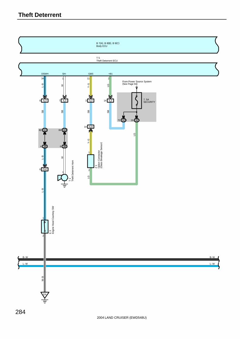
2004 LAND CRUISER (EWD548U)
284
Theft Deterrent
B 7(A), B 8(B), B 9(C)
IL38
3Q82
3B4
EA26
2
1
EA
IL37
6 3B
84 3Q
1
E 3
T 1
IL33
IU314
7. 5ASECURITY
From Power Source System(See Page 94)
3E163Q72
IL314
Z 1
L- W
34 1 11 2
DSWH SH- GBS +B1
L-B
W Y-G LG
SB
SB
SB
SB
LG
L-B
W
Y-G
L-B
W-B
T 5
LG
2
1
L- W
B- W
Eng
ine
Hoo
d C
ourt
esy
SW
The
ft D
eter
rent
Hor
n
Theft Deterrent ECU
Body ECU
B- W
Opt
ion
Con
nect
or( G
lass
Bre
akag
e S
enso
r)
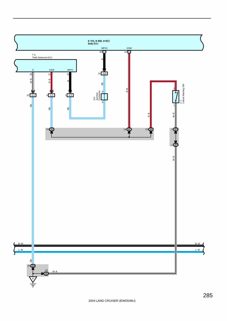
2004 LAND CRUISER (EWD548U)
285
B 7(A), B 8(B), B 9(C)B 7(A), B 8(B), B 9(C)
L- W
B- W
B
12 31
R-B
MPX1
SB
KSW
IL39 IL31
E
E
IU315
14C
KSW
26 C
74 3Q
SB
SB
B
MPX3
18 3E 23 3ER
-B
1
2
1 3P
3 3P
R-B
J14
U 1
W-B
W-B
L- W
B- W
T 5
W-B
29
E
IL322
IF
2Q20
2E
18 W- B
SB
SB
Theft Deterrent ECU
Unl
ock
War
ning
SW
Body ECUBody ECU
Junc
tion
Con
nect
or

2004 LAND CRUISER (EWD548U)
286
Theft Deterrent
B 7(A), B 8(B), B 9(C)
L- W
B- W
W-B
W- B W- B
L-B
W-B
W-B
G-B
LSWD
L-W
KEYEGNDKUL
24 A
IC211
7
MPX1
BB
MPX1
P12
20AP/W(FL)
From Power Source System (See Page 94)
3E1
2E42
2I7
KL
1632144
D18
LB
-W
L-W
20 9
SIG CPUB
Unl
ock
Lock
3
2 1
B 2
2I8
IF
B 2B 2
10
BDR
L
W-B
BS18
BS14
1
4
L-B
W-B
W-B
D21
Doo
r K
ey L
ock
and
Unl
ock
SW
LH
Doo
r U
nloc
k D
etec
tion
SW
Fro
nt L
H
Power Window Master SW
Body ECU
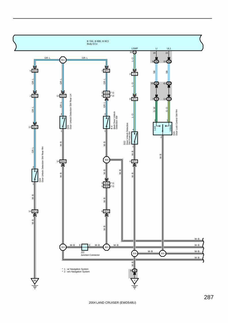
2004 LAND CRUISER (EWD548U)
287
B 7(A), B 8(B), B 9(C)
W- B
BC414
W- B
BK
BC413
BL52
BD49
4
1
W-B
W-B
GR
-LG
R-L
D24
GR
-L
B 4
D23
6 BP3
D20
B11
B 6 B11
B15
2
W- B
W-B
W-B
W-B
SB
SB
G-O
G-W
L-O
L-O
L-O
W- B
UL1LI
1519
W-B
EW- B
14
E
B 8 B 8
D22
4
1
LSWP
41 3Q
10 2Q9 2Q
13 3J7 3I
35 3Q
13
Lock
Unl
ock
W-B
W-B
W-B
GR- L
5 BH2
4 BT1
GR
-L
GR
-LG
R-L
GR
-L
BT18
7 BP3
13 BA4
W-B
1
4
J22
W-B
1
4
BA4
IY24
A30
W- B
W- B
W-B
W- B
3I9
II
W-B
GR- L
Bac
k D
oor
Unl
ock
Det
ectio
n S
W
Doo
r Lo
ck C
ontr
ol S
W R
H
Doo
r U
nloc
k D
etec
tion
SW
Rea
r LH
Doo
r U
nloc
k D
etec
tion
SW
Rea
r R
HBody ECU
Junction Connector
Doo
r U
nloc
k D
etec
tion
SW
Fro
nt R
H
BH15BH13 (*1)
(*2)
BH23 (*1)(*2)
* 2 : w/o Navigation System* 1 : w/ Navigation System
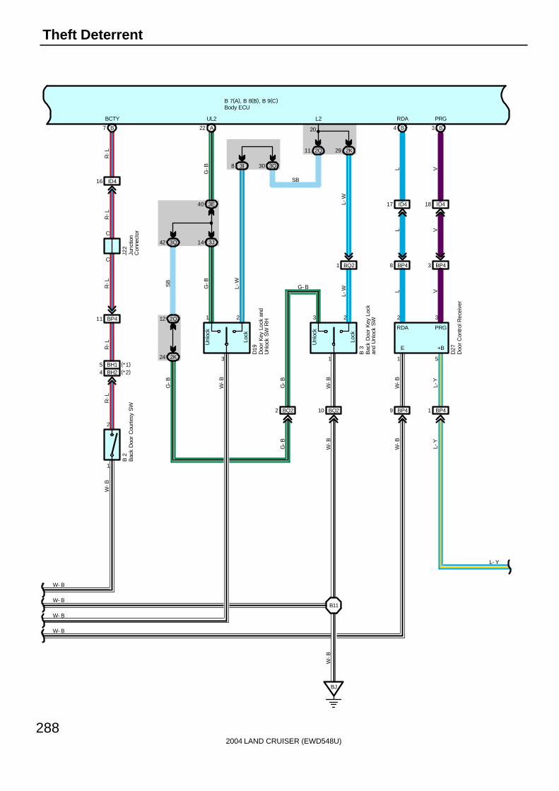
2004 LAND CRUISER (EWD548U)
288
Theft Deterrent
B 7(A), B 8(B), B 9(C)
21
3
Unl
ock
Lock
Lock
Unl
ock
1
3 2
BQ22 BQ210 BP49 BP41
24 2K
12 2Q
14 3J
40 3E
42 3Q
3I8 3Q30
2K292Q11
A22
BP48 BP43
ID417 ID418
B4 B3
D27
D19
B 3
G-B
SB
G-B
L-W
G-B
W-B
G-B
W-B
W-B
L-Y
L V
L V
L V
G-B
W-B
W-B
L-Y
L-W
SB
G- B
UL2 L2 RDA PRG
20
1 5
2 3
BQ21
L-W
B11
BJ
W-B
W- B
W- B
W- B
W- B
BCTY
W-B
R-L
R-L
R-L
R-L
R-L
B 2
J22
4 BH2
11 BP4
C
C
7 B
16 ID4
2
1
L- Y
Bac
k D
oor
Cou
rtes
y S
W
Bac
k D
oor
Key
Loc
kan
d U
nloc
k S
W
Doo
r K
ey L
ock
and
Unl
ock
SW
RH
Body ECU
Junc
tion
Con
nect
or
Doo
r C
ontr
ol R
ecei
ver
PRGRDA
+BE
BH15 (*1)(*2)

2004 LAND CRUISER (EWD548U)
289
B 7(A), B 8(B), B 9(C)
1 1
10 2K
8 2E
26 3K
15 3E
B23 B24
D14
D15
R-Y
R-B
R-Y
R-B
DCTY PCTY
3 A
DO
ME
Rel
ay
R-W
22 1B
15AAM2
HE
AD
Rel
ay1 5
2 3
2G1
2K9 2Q79
R-W
L-Y
LMRY
SB
10ADOME
3Q17
From Power Source System (See Page 94)
R-W
R-W
HR
20 C
HRLY
17
11 2E5 2B
E
E
J 9
R-W
L- Y
Doo
r C
ourt
esy
SW
Fro
nt L
H
Doo
r C
ourt
esy
SW
Fro
nt R
H
Body ECU
JunctionConnector
* 2 : w/o Navigation System* 1 : w/ Navigation System
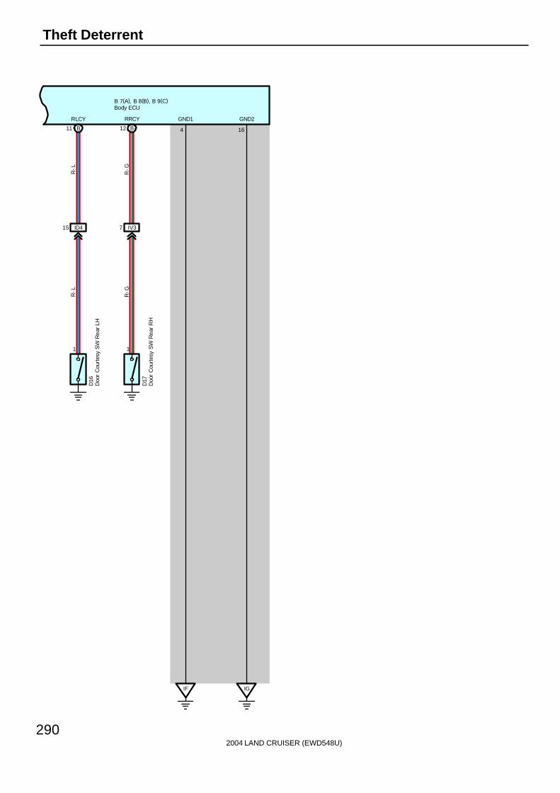
2004 LAND CRUISER (EWD548U)
290
Theft Deterrent
B 7(A), B 8(B), B 9(C)
1 1
B11 B12
ID415 IV37
D16
R-L
R-G
R-L
R-G
RLCY RRCY
IF IG
4 16
GND1 GND2
D17
Doo
r C
ourt
esy
SW
Rea
r LH
Doo
r C
ourt
esy
SW
Rea
r R
H
Body ECU

2004 LAND CRUISER (EWD548U)
291
D18, D19 Door Key Lock and Unlock SW LH, RH1-3 : Closed with door lock cylinder unlocked with key2-3 : Closed with door lock cylinder locked with key
B3 Back Door Key Lock and Unlock SW3-1 : Closed with door lock cylinder unlocked with key2-1 : Closed with door lock cylinder locked with key
E3 Engine Hood Courtesy SW1-2 : Opened with engine hood open
U1 Unlock Warning SW2-1 : Closed with ignition key in cylinder
T5 Theft Deterrent ECU2, 3-Ground : Always approx. 12 volts10-Ground : Approx. 12 volts with ignition SW at ON or ST position29-Ground : Always continuity12-Ground : Continuity with ignition key in cylinder34-Ground : Continuity with engine hood close
: Parts Location
Code See Page Code See Page Code See Page
B2 72 D18 72 J10 71
B3 72 D19 72 J14 71
B4 72 D20 72 J22 72
B7 A 70 D21 72 M5 A 71
B8 B 70 D22 72 M9 B 71
B9 C 70 D23 72 P12 73
D7 70 D24 72 T1 69
D14 72 D27 72 T5 71
D15 72 E3 68 U1 71
D16 72 F15 68 Z1 71
D17 72 J9 71
: Junction Block and Wire Harness Connector
Code See Page Junction Block and Wire Harness (Connector Location)
1B24 Engine Room No 2 Wire and Engine Room J/B (Engine Compartment Left)
1C24 Engine Room No.2 Wire and Engine Room J/B (Engine Compartment Left)
2B 28 Engine Room No.2 Wire and Cowl Side J/B LH (Left Kick Panel)
2E28 Dash Wire and Cowl Side J/B LH (Left Kick Panel)
2G28 Dash Wire and Cowl Side J/B LH (Left Kick Panel)
2I 28 Front Door LH Wire and Cowl Side J/B LH (Left Kick Panel)
2K 28 Floor No.1 Wire and Cowl Side J/B LH (Left Kick Panel)
2Q 30 Instrument Panel Integration Wire and Cowl Side J/B LH (Left Kick Panel)
3B 40 Engine Room No.2 Wire and Cowl Side J/B RH (Right Kick Panel)
3D40 Dash Wire and Cowl Side J/B RH (Right Kick Panel)
3E40 Dash Wire and Cowl Side J/B RH (Right Kick Panel)
3I40 Front Door RH Wire and Cowl Side J/B RH (Right Kick Panel)
3J40 Front Door RH Wire and Cowl Side J/B RH (Right Kick Panel)
3K 40 Floor No.2 Wire and Cowl Side J/B RH (Right Kick Panel)
3P 43 Dash Wire and Cowl Side J/B RH (Right Kick Panel)
3Q 42 Instrument Panel Integration Wire and Cowl Side J/B RH (Right Kick Panel)
4D 52 Dash Wire and J/B No.4 (Instrument Panel Center)
5B 56 Dash Wire and J/B No.5 (Behind the Combination Meter)
5D 56 Engine Room No.2 Wire and J/B No.5 (Behind the Combination Meter)
7B 64 Dash Wire and J/B No.7 (Behind the Grove Box)
Service Hints
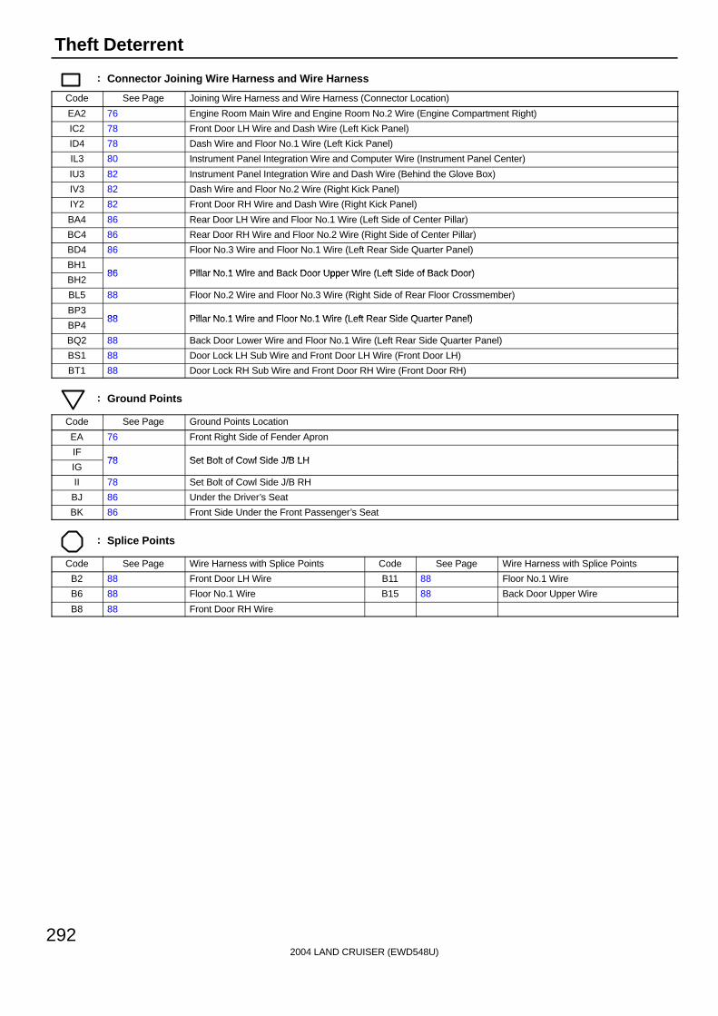
2004 LAND CRUISER (EWD548U)
292
Theft Deterrent
: Connector Joining Wire Harness and Wire Harness
Code See Page Joining Wire Harness and Wire Harness (Connector Location)
EA2 76 Engine Room Main Wire and Engine Room No.2 Wire (Engine Compartment Right)
IC2 78 Front Door LH Wire and Dash Wire (Left Kick Panel)
ID4 78 Dash Wire and Floor No.1 Wire (Left Kick Panel)
IL3 80 Instrument Panel Integration Wire and Computer Wire (Instrument Panel Center)
IU3 82 Instrument Panel Integration Wire and Dash Wire (Behind the Glove Box)
IV3 82 Dash Wire and Floor No.2 Wire (Right Kick Panel)
IY2 82 Front Door RH Wire and Dash Wire (Right Kick Panel)
BA4 86 Rear Door LH Wire and Floor No.1 Wire (Left Side of Center Pillar)
BC4 86 Rear Door RH Wire and Floor No.2 Wire (Right Side of Center Pillar)
BD4 86 Floor No.3 Wire and Floor No.1 Wire (Left Rear Side Quarter Panel)
BH186 Pillar No 1 Wire and Back Door Upper Wire (Left Side of Back Door)
BH286 Pillar No.1 Wire and Back Door Upper Wire (Left Side of Back Door)
BL5 88 Floor No.2 Wire and Floor No.3 Wire (Right Side of Rear Floor Crossmember)
BP388 Pillar No 1 Wire and Floor No 1 Wire (Left Rear Side Quarter Panel)
BP488 Pillar No.1 Wire and Floor No.1 Wire (Left Rear Side Quarter Panel)
BQ2 88 Back Door Lower Wire and Floor No.1 Wire (Left Rear Side Quarter Panel)
BS1 88 Door Lock LH Sub Wire and Front Door LH Wire (Front Door LH)
BT1 88 Door Lock RH Sub Wire and Front Door RH Wire (Front Door RH)
: Ground Points
Code See Page Ground Points Location
EA 76 Front Right Side of Fender Apron
IF78 Set Bolt of Cowl Side J/B LH
IG78 Set Bolt of Cowl Side J/B LH
II 78 Set Bolt of Cowl Side J/B RH
BJ 86 Under the Driver’s Seat
BK 86 Front Side Under the Front Passenger’s Seat
: Splice Points
Code See Page Wire Harness with Splice Points Code See Page Wire Harness with Splice Points
B2 88 Front Door LH Wire B11 88 Floor No.1 Wire
B6 88 Floor No.1 Wire B15 88 Back Door Upper Wire
B8 88 Front Door RH Wire

2004 LAND CRUISER (EWD548U)
293
Memo
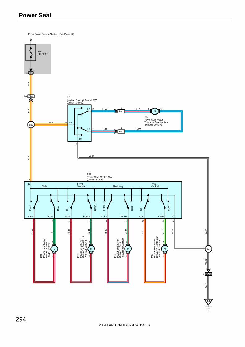
2004 LAND CRUISER (EWD548U)
294
Power Seat
30ALH SEAT
From Power Source System (See Page 94)
2K1
BM310
B27
BN1
2
BN1
1
12
E2
B2
2
1
LR
LF
4
3
SLDF
Rea
r
Fron
t
Dow
n
Up
8 4
SLDR
2 3
12
FrontVertical
FUP
Dow
n
Up
10 9
FDWN RCLF
Rea
r
Fron
t
1 5
RCLR
2
1
R-W G
1
2
R-B
G-B
2
1
R-L
G-R
1
2
R-Y
G-Y
BJ
BM38
B27
6
LUP LDWN E
BSlide Reclining
RearVertical
W-B
W-B
W-B
W-B
Y-R
Y-R
Y-R
W- B
Y- R
L- W
L- R
L- R
L- W
P29
P25
P28
P27
L 3
P23
P26
Lumbar Support Control SW(Driver’ s Seat)
Power Seat Control SW(Driver’ s Seat)
Pow
er S
eat M
otor
( Driv
er’
s S
eat F
ront
Ver
tical
Con
trol)
Power Seat Motor(Driver’ s Seat Lumbar Support Control)
Pow
er S
eat M
otor
( Driv
er’
s S
eat R
ear
Ver
tical
Con
trol)
Pow
er S
eat M
otor
( Driv
er’
s S
eat
Rec
linin
g C
ontr
ol)
Pow
er S
eat M
otor
( Driv
er’
s S
eat
Slid
e C
ontr
ol)
M M M M
M
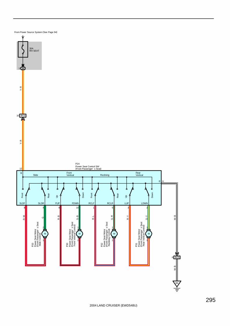
2004 LAND CRUISER (EWD548U)
295
BO310
SLDF
Rea
r
Fron
t
Dow
n
Up
8 4
SLDR
3 2
12
FrontVertical
FUP
Dow
n
Up
9 10
FDWN RCLF
Rea
r
Fron
t
1 5
RCLR
1
2
R-W G
2
1
R-B
G-B
2
1
R-L
G-R
2
1
R-Y
G-Y
LUP LDWN
6
BSlide Reclining
RearVertical
W-B
E
BK
BO38
Y-R
Y-R
W-B
30ARH SEAT
From Power Source System (See Page 94)
3K1
P33
P30
P32
P31
P24Power Seat Control SW(Front Passenger’ s Seat)
Pow
er S
eat M
otor
( Fro
nt P
asse
nger
’s
Sea
t F
ront
Ver
tical
Con
trol
)
Pow
er S
eat M
otor
( Fro
nt P
asse
nger
’s
Sea
t R
ear
Ver
tical
Con
trol
)
Pow
er S
eat M
otor
( Fro
nt P
asse
nger
’s
Sea
t R
eclin
ing
Con
trol)
Pow
er S
eat M
otor
( Fro
nt P
asse
nger
’s
Sea
t S
lide
Con
trol
) M M M M

2004 LAND CRUISER (EWD548U)
296
Power Seat
P23 Power Seat Control SW (Driver’s Seat)12-1 : Closed with driver’s seat at front reclining operation12-5 : Closed with driver’s seat at rear reclining operation
12-10 : Closed with driver’s seat at front vertical up operation12-9 : Closed with driver’s seat at front vertical down operation12-2 : Closed with driver’s seat at rear vertical up operation12-3 : Closed with driver’s seat at rear vertical down operation12-8 : Closed with driver’s seat at front slide operation12-4 : Closed with driver’s seat at rear slide operation6-Ground : Always continuity
P24 Power Seat Control SW (Front Passenger’s Seat)12-1 : Closed with front passenger’s seat at front reclining operation12-5 : Closed with front passenger’s seat at rear reclining operation12-9 : Closed with front passenger’s seat at front vertical up operation
12-10 : Closed with front passenger’s seat at front vertical down operation12-3 : Closed with front passenger’s seat at rear vertical up operation12-2 : Closed with front passenger’s seat at rear vertical down operation12-8 : Closed with front passenger’s seat at front slide operation12-4 : Closed with front passenger’s seat at rear slide operation6-Ground : Always continuity
: Parts Location
Code See Page Code See Page Code See Page
L3 74 P26 74 P30 74
P23 74 P27 74 P31 74
P24 74 P28 74 P32 74
P25 74 P29 74 P33 74
: Junction Block and Wire Harness Connector
Code See Page Junction Block and Wire Harness (Connector Location)
2K 28 Floor No.1 Wire and Cowl Side J/B LH (Left Kick Panel)
3K 40 Floor No.2 Wire and Cowl Side J/B RH (Right Kick Panel)
: Connector Joining Wire Harness and Wire Harness
Code See Page Joining Wire Harness and Wire Harness (Connector Location)
BM3 90 Floor No.1 Wire and Front Seat LH Wire (Front Side Under the Driver’s Seat)
BN1 90 Seat No.2 Wire and Front Seat LH Wire (Rear Side Under the Driver’s Seat)
BO3 90 Floor No.2 Wire and Front Seat RH Wire (Front Side Under the Front Passenger’s Seat)
: Ground Points
Code See Page Ground Points Location
BJ 86 Under the Driver’s Seat
BK 86 Front Side Under the Front Passenger’s Seat
: Splice Points
Code See Page Wire Harness with Splice Points Code See Page Wire Harness with Splice Points
B27 90 Front Seat LH Wire
Service Hints

2004 LAND CRUISER (EWD548U)
297
Memo

2004 LAND CRUISER (EWD548U)
298
Power Tilt and Power Telescopic
MSWVC
TiltDown
TelescopicShort
Tilt Up
TelescopicLong
A2 A5
II58 II59
16 8
C17
B14
II512
7
5 B
II511
8
13 B
II510
3
15 B
II318
5
6 B
II315
6
16 B
II317
4
7 B
II316
1
I 9
B L P( *1)
( *1)
(* 1)
G B V P( *1)
T 9
20ATIL &TEL
3D38
10AECU- IG2
From Power Source System (See Page 94)
3D37
10AECU- B2
3D39
B4 A4 A1
G-B
B-W
L-W
+B IG ECUB
T 7(A), T 8(B)
VC MSW SG1 SIN1 S5V1 COM1 F/B1 B1 A1
SG1 SIN1 S5V1 COM1 F/B1 B1 A1
V
V-Y
G-Y
G-R
G-W
V
V-Y
G-Y
G-R
G-W
Y( *
1)
Combination SW
Tilt and Telescopic ECU
Tilt Motor
* 2 : w/ Side Airbag* 1 : Shielded
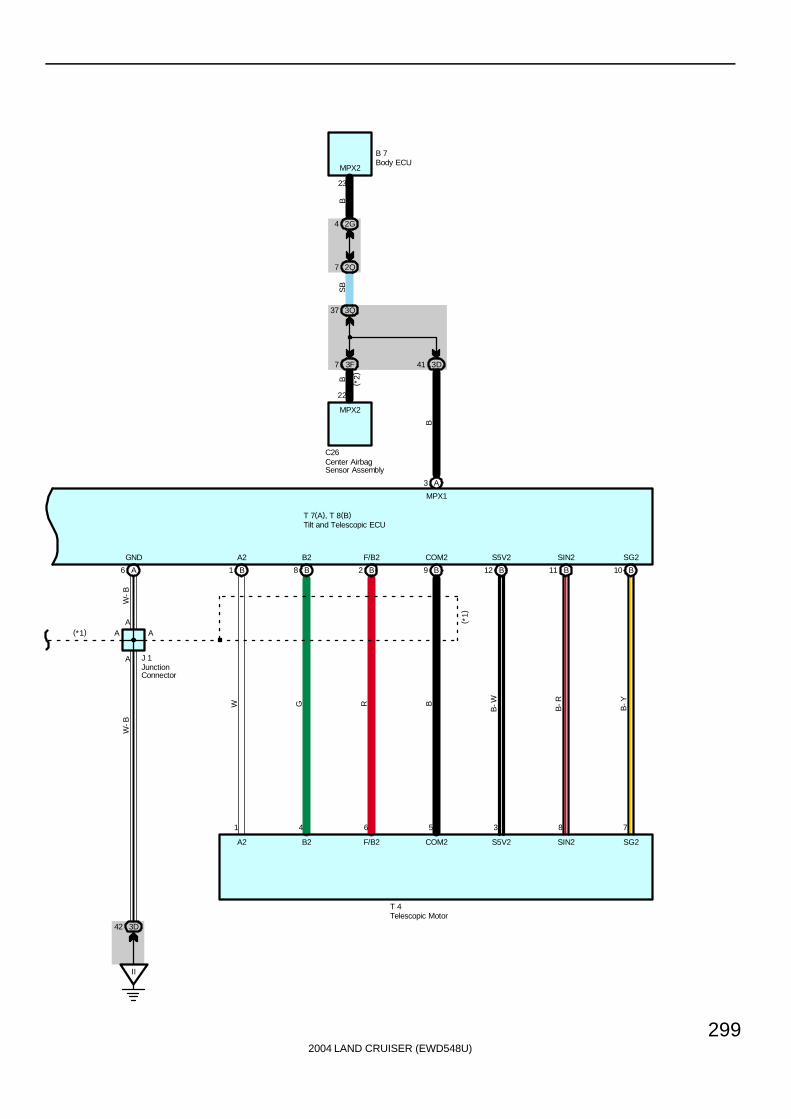
2004 LAND CRUISER (EWD548U)
299
A6
II
3D42
(*1)
A
AA
A
J 1
W-B
1
B1
4
B8
6
B2
5
B9
3
B12
8
B11
7
B10
( *1)
W
W-B
G R B
B-W B-R
B-Y
T 4
GND A2 B2 F/B2 COM2 S5V2 SIN2 SG2
A2 B2 F/B2 COM2 S5V2 SIN2 SG2
T 7(A), T 8(B)
Telescopic Motor
Tilt and Telescopic ECU
JunctionConnector
MPX2
4
2Q
22
C26
2G
7
3F7
3Q37
BS
BB
B 7
MPX2
Center AirbagSensor Assembly
Body ECU
A3
B
MPX1
( *2)
3D41
23

2004 LAND CRUISER (EWD548U)
300
Power Tilt and Power Telescopic
This system provides the automatic tilt and telescopic mechanisms using the motor drive, tilt and telescopic ECU control,allowing variable steering movement in the back and forth, and vertical directions. This makes it possible to set the steeringto the desired steering position.
T7 (A), T8 (B) Tilt and Telescopic ECU(A) 1-Ground : Always approx. 12 volts(B) 4-Ground : Always approx. 12 volts(A) 4-Ground : Approx. 12 volts with ignition SW at ON or ST position(A) 6-Ground : Always continuity
C17 Combination SW16-8 : Approx. 160 Ω with telescopic long operation
: Approx. 360 Ω with tilt up operation: Approx. 790 Ω with telescopic short operation: Approx. 1.99 kΩ with tilt down operation
: Parts Location
Code See Page Code See Page Code See Page
B7 70 J1 71 T8 B 71
C17 70 T4 71 T9 71
C26 70 T7 A 71
: Junction Block and Wire Harness Connector
Code See Page Junction Block and Wire Harness (Connector Location)
2G 28 Dash Wire and Cowl Side J/B LH (Left Kick Panel)
2Q 30 Instrument Panel Integration Wire and Cowl Side J/B LH (Left Kick Panel)
3D40 Dash Wire and Cowl Side J/B RH (Right Kick Panel)
3F40 Dash Wire and Cowl Side J/B RH (Right Kick Panel)
3Q 42 Instrument Panel Integration Wire and Cowl Side J/B RH (Right Kick Panel)
: Connector Joining Wire Harness and Wire Harness
Code See Page Joining Wire Harness and Wire Harness (Connector Location)
II380 Dash Wire and Column Wire (Near the Ignition SW)
II580 Dash Wire and Column Wire (Near the Ignition SW)
: Ground Points
Code See Page Ground Points Location
II 78 Set Bolt of Cowl Side J/B RH
: Splice Points
Code See Page Wire Harness with Splice Points Code See Page Wire Harness with Splice Points
I9 80 Column Wire
System Outline
Service Hints

2004 LAND CRUISER (EWD548U)
301
Memo

2004 LAND CRUISER (EWD548U)
302
Remote Control Mirror
7. 5AACC
From Power Source System (See Page 94)
2Q44
IF213
M M
MH MV M+
8 6 7
R32
M M
MH MV M+
8 6 7
R33
2J11
2Q47
G-R
2J4
Y-R
2Q48 4 2Q
W
14 2J 3J10
Y
3Q57
3J11
G
3Q66
E
E D
D
RHRH LHLH
Left
Rig
ht Up
Dow
n
Left
/Up
Rig
ht/D
own
Ope
ratio
n S
WS
elec
t S
W
9 10 3 2 7 8
MRVMRH MLVMLH M+ E
B
4
SB
GR
R 5
IF
2Q43
A
A
IF211IF219IF25IF216IF24IF215
3Q61
3J3
3Q
33
J 6 J12
W-BWY
Y-RG
G-R
SB
SB
SB
W SB
SB
SB
SB
SB
SB
SB
SB
SB
Remote Control Mirror SW
Remote Control Mirror LH Remote Control Mirror RH
JunctionConnector
JunctionConnector

2004 LAND CRUISER (EWD548U)
303
R5 Remote Control Mirror SW7-8 : Continuity with operation SW at LEFT or UP position4-7 : Continuity with operation SW at RIGHT or DOWN position4-9 : Continuity with operation SW at LEFT position and the select SW at LH position4-3 : Continuity with operation SW at UP position and the select SW at LH position
8-10 : Continuity with operation SW at RIGHT position and the select SW at RH position2-8 : Continuity with operation SW at DOWN position and the select SW at RH position
4-Ground : Approx. 12 volts with ignition SW at ACC or ON position8-Ground : Always continuity
: Parts Location
Code See Page Code See Page Code See Page
J6 71 R5 71 R33 73
J12 71 R32 73
: Junction Block and Wire Harness Connector
Code See Page Junction Block and Wire Harness (Connector Location)
2J 28 Front Door LH Wire and Cowl Side J/B LH (Left Kick Panel)
2Q 30 Instrument Panel Integration Wire and Cowl Side J/B LH (Left Kick Panel)
3J 40 Front Door RH Wire and Cowl Side J/B RH (Right Kick Panel)
3Q 42 Instrument Panel Integration Wire and Cowl Side J/B RH (Right Kick Panel)
: Connector Joining Wire Harness and Wire Harness
Code See Page Joining Wire Harness and Wire Harness (Connector Location)
IF2 78 Instrument Panel Integration Wire and Instrument Panel Wire (Left Side of Instrument Panel)
: Ground Points
Code See Page Ground Points Location
IF 78 Set Bolt of Cowl Side J/B LH
Service Hints

2004 LAND CRUISER (EWD548U)
304
Automatic Glare-Resistant EC Mirror with Compass
10AECU- IG1
From Power Source System (See Page 94)
2L19
4
1
IF
2L11
E
IG I22
B-W
W-B
Inner Mirror
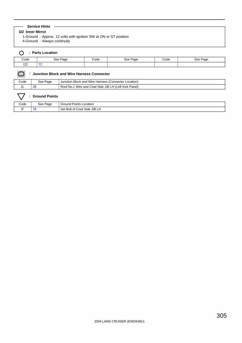
2004 LAND CRUISER (EWD548U)
305
I22 Inner Mirror1-Ground : Approx. 12 volts with ignition SW at ON or ST position4-Ground : Always continuity
: Parts Location
Code See Page Code See Page Code See Page
I22 72
: Junction Block and Wire Harness Connector
Code See Page Junction Block and Wire Harness (Connector Location)
2L 28 Roof No.1 Wire and Cowl Side J/B LH (Left Kick Panel)
: Ground Points
Code See Page Ground Points Location
IF 78 Set Bolt of Cowl Side J/B LH
Service Hints

2004 LAND CRUISER (EWD548U)
306
Power Rear Quarter Window
Ope
n
Clo
se
Clo
se
Ope
n
10AGAUGE1
From Power Source System (See Page 94)
2Q65
A
A
IF11
4 4
CLSCLS
BB
5 3 6 6 5 3
OPEN OPENE E
IF115
R
IF116
P
IF113
Y-R
IF114
Y
2Q60 2Q59 3Q47 3Q48
2K37 2K36 3K36 3K40
BP44 BP45 IF211 BI12 BI11
1 2 1 2
A
A
IF
2Q43
SB
SB
W-B
W-B
W-B
SB
SB
R P
Y-R Y
SB
SB
R P
Y-R Y
R-L
R-L
SB
SB
R- L
P 6 P 7
J14
J12
P10 P11
I19
I18
Power QuarterWindow SW LH
Power QuarterWindow SW RH
Power Vent WindowMotor LH
Power Vent WindowMotor RH
JunctionConnector
JunctionConnector
M M
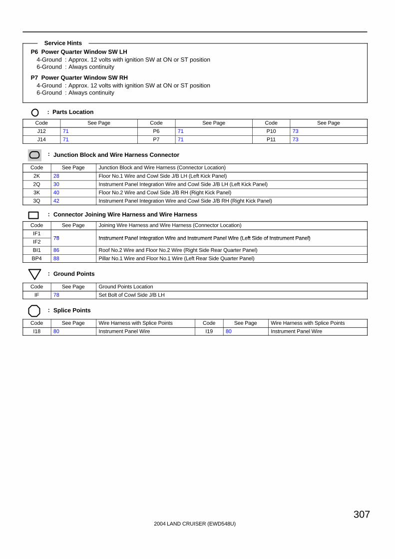
2004 LAND CRUISER (EWD548U)
307
P6 Power Quarter Window SW LH4-Ground : Approx. 12 volts with ignition SW at ON or ST position6-Ground : Always continuity
P7 Power Quarter Window SW RH4-Ground : Approx. 12 volts with ignition SW at ON or ST position6-Ground : Always continuity
: Parts Location
Code See Page Code See Page Code See Page
J12 71 P6 71 P10 73
J14 71 P7 71 P11 73
: Junction Block and Wire Harness Connector
Code See Page Junction Block and Wire Harness (Connector Location)
2K 28 Floor No.1 Wire and Cowl Side J/B LH (Left Kick Panel)
2Q 30 Instrument Panel Integration Wire and Cowl Side J/B LH (Left Kick Panel)
3K 40 Floor No.2 Wire and Cowl Side J/B RH (Right Kick Panel)
3Q 42 Instrument Panel Integration Wire and Cowl Side J/B RH (Right Kick Panel)
: Connector Joining Wire Harness and Wire Harness
Code See Page Joining Wire Harness and Wire Harness (Connector Location)
IF178 Instrument Panel Integration Wire and Instrument Panel Wire (Left Side of Instrument Panel)
IF278 Instrument Panel Integration Wire and Instrument Panel Wire (Left Side of Instrument Panel)
BI1 86 Roof No.2 Wire and Floor No.2 Wire (Right Side Rear Quarter Panel)
BP4 88 Pillar No.1 Wire and Floor No.1 Wire (Left Rear Side Quarter Panel)
: Ground Points
Code See Page Ground Points Location
IF 78 Set Bolt of Cowl Side J/B LH
: Splice Points
Code See Page Wire Harness with Splice Points Code See Page Wire Harness with Splice Points
I18 80 Instrument Panel Wire I19 80 Instrument Panel Wire
Service Hints

2004 LAND CRUISER (EWD548U)
308
Seat Heater
IG
ELOHI
HI HILO
4
L- W
3 5 6
3 2 1 4 3 2
1
BM38
W-B
W-B
BJ
BC
AA
BB
AB
ID38 ID39
BM35 BM36AE
BD BD
II
3D1 3K31
W- B
W- B
J18(
A) ,
J19
( B)
S 9 S15
J18(
A) ,
J19(
B)
R-G
B-R
R-G
B-R
R-G
B-R
W-B
B- R
R- G
W- B
B-R
B-R
R-G
L- W
R- G
S 3Seat Heater SW(Driver’ s Seat)
Seat Heater(Driver’ s Seat)
Junc
tion
Con
nect
or
Junc
tion
Con
nect
or
Seat Heater(Driver’ s Seat Cushion)
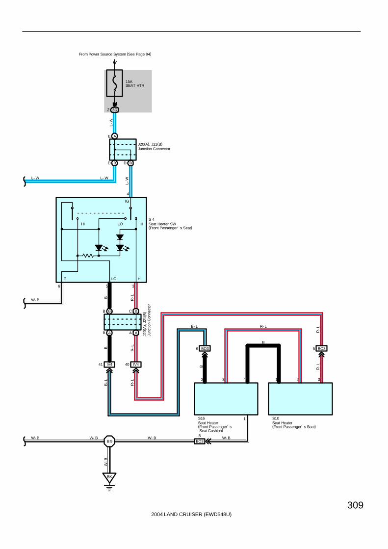
2004 LAND CRUISER (EWD548U)
309
LOE HI
IG
HILOHI
15ASEAT HTR
From Power Source System (See Page 94)
3D2L-
W
BD BD
AE
L-W
4
J20(A), J21(B)
6 5 3
A A
C B
B A
B B
1
321432
IV441 IV440
BO36 BO35
BO38
B 9
BK
W- B
W- B
L- W L- W
B R-L
B R-L
B-L
R-L
B R-L
R-L
B
R- L
W- B W- B W- B
W-B
J20(
A) ,
J21(
B)
S16 S10
S 4
B- L
Seat Heater SW(Front Passenger’ s Seat)
Seat Heater(Front Passenger’ s Seat)
Junction ConnectorJu
nctio
n C
onne
ctor
Seat Heater(Front Passenger’ s Seat Cushion)

2004 LAND CRUISER (EWD548U)
310
Seat Heater
S3 Seat Heater SW (Driver’s Seat)4-Ground : Approx. 12 volts with ignition SW at ON or ST position6-Ground : Always continuity
S4 Seat Heater SW (Front Passenger’s Seat)4-Ground : Approx. 12 volts with ignition SW at ON or ST position6-Ground : Always continuity
: Parts Location
Code See Page Code See Page Code See Page
J18 A 71 S3 71 S15 74
J19 B 71 S4 71 S16 74
J20 A 71 S9 74
J21 B 71 S10 74
: Junction Block and Wire Harness Connector
Code See Page Junction Block and Wire Harness (Connector Location)
3D 40 Dash Wire and Cowl Side J/B RH (Right Kick Panel)
3K 40 Floor No.2 Wire and Cowl Side J/B RH (Right Kick Panel)
: Connector Joining Wire Harness and Wire Harness
Code See Page Joining Wire Harness and Wire Harness (Connector Location)
ID3 78 Dash Wire and Floor No.1 Wire (Left Kick Panel)
IV4 82 Dash Wire and Floor No.2 Wire (Right Kick Panel)
BM3 90 Floor No.1 Wire and Front Seat LH Wire (Front Side Under the Driver’s Seat)
BO3 90 Floor No.2 Wire and Front Seat RH Wire (Front Side Under the Front Passenger’s Seat)
: Ground Points
Code See Page Ground Points Location
II 78 Set Bolt of Cowl Side J/B RH
BJ 86 Under the Driver’s Seat
BK 86 Front Side Under the Front Passenger’s Seat
: Splice Points
Code See Page Wire Harness with Splice Points Code See Page Wire Harness with Splice Points
B9 88 Floor No.2 Wire
Service Hints

2004 LAND CRUISER (EWD548U)
311
Memo
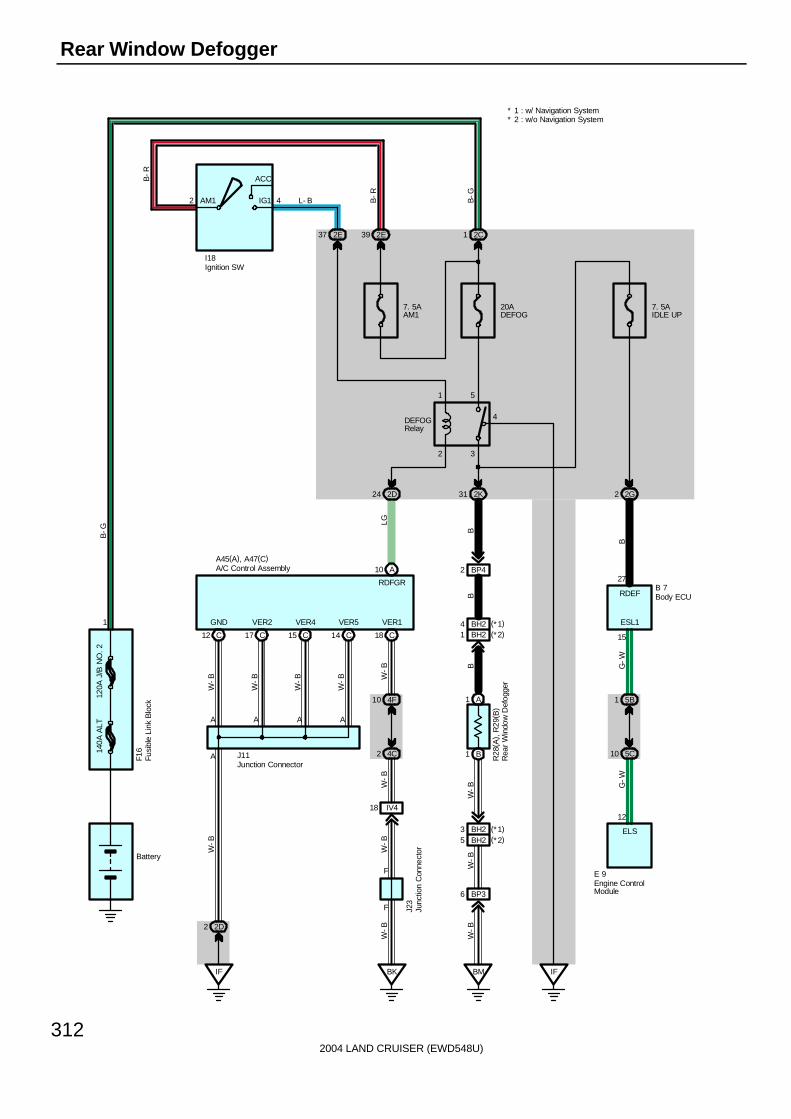
2004 LAND CRUISER (EWD548U)
312
Rear Window Defogger
140A
ALT
120A
J/B
NO
. 2
2 4AM1
ACC
IG1
BM
W-B
BP36
W-B
BH25
W-B
A1
B1
B
BH21
B
BP42
B
2K31
2 3
1 5
4
7. 5AAM1
2C1
IF
2G2
7. 5AIDLE UP
2E392E37
2D24
C18
W-B
4F10
4C2
W-B
IV418
BK
W-B
W-B
F
F
A10
IF
C12 C17 C15 C14
A
15
27
AAAA
G-W
5B1
5C10
12
G-W
B
LG
W-B
W-B
W-B
W-B
W-B
B-G
B-R
B-G
B-R
L- B
E 9
J11
B 7
A45(A), A47(C)
F16
R28
( A) ,
R29
( B)
J23
Battery
20ADEFOG
I18
DEFOGRelay
RDEF
ESL1
ELS
RDFGR
VER1VER5VER4VER2GND
2D2
Engine ControlModule
Ignition SW
Rea
r W
indo
w D
efog
ger
A/C Control Assembly
Body ECU
Junction Connector
Junc
tion
Con
nect
or
Fusi
ble
Link
Blo
ck
1 BH24 (*1)(*2)
BH23 (*1)(*2)
* 2 : w/o Navigation System* 1 : w/ Navigation System
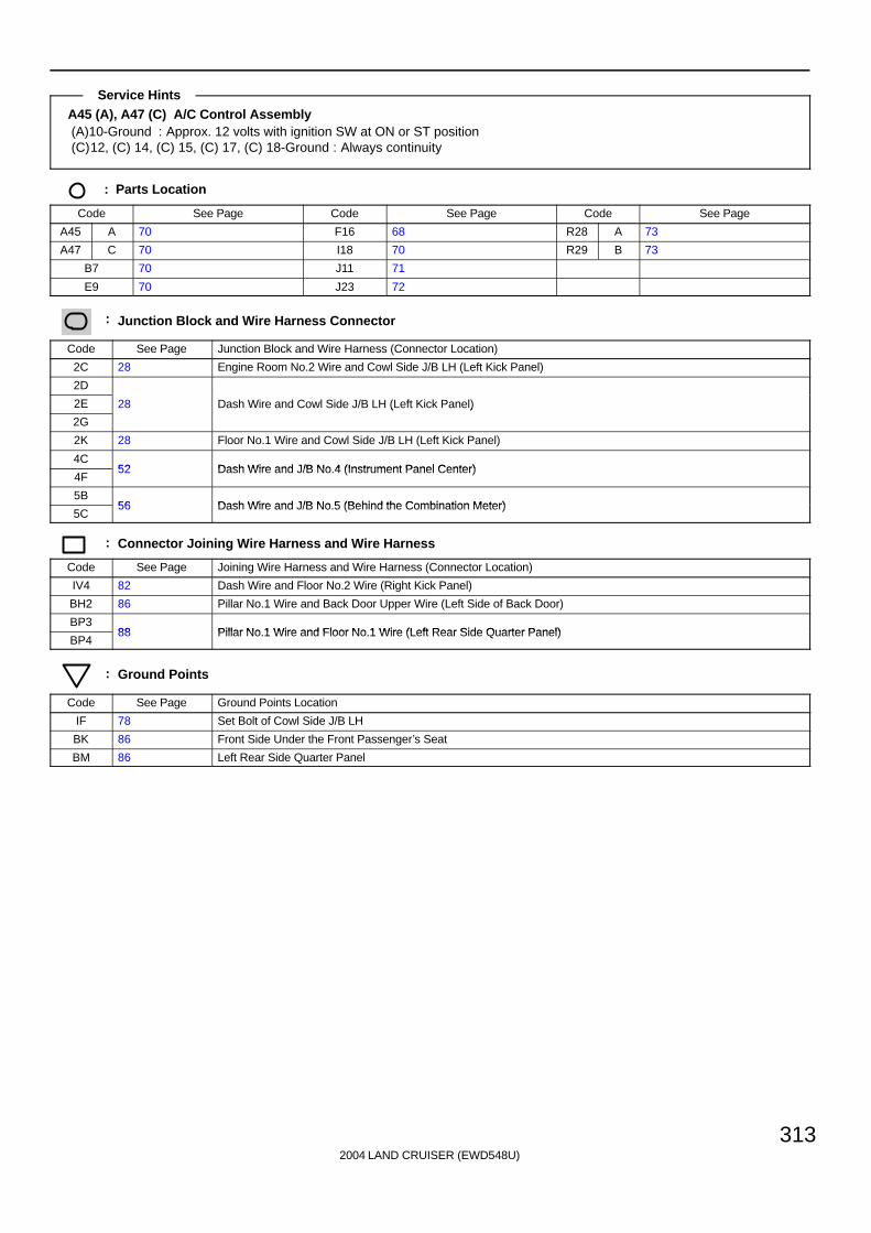
2004 LAND CRUISER (EWD548U)
313
A45 (A), A47 (C) A/C Control Assembly(A)10-Ground : Approx. 12 volts with ignition SW at ON or ST position(C)12, (C) 14, (C) 15, (C) 17, (C) 18-Ground : Always continuity
: Parts Location
Code See Page Code See Page Code See Page
A45 A 70 F16 68 R28 A 73
A47 C 70 I18 70 R29 B 73
B7 70 J11 71
E9 70 J23 72
: Junction Block and Wire Harness Connector
Code See Page Junction Block and Wire Harness (Connector Location)
2C 28 Engine Room No.2 Wire and Cowl Side J/B LH (Left Kick Panel)
2D
2E 28 Dash Wire and Cowl Side J/B LH (Left Kick Panel)
2G
( )
2K 28 Floor No.1 Wire and Cowl Side J/B LH (Left Kick Panel)
4C52 Dash Wire and J/B No 4 (Instrument Panel Center)
4F52 Dash Wire and J/B No.4 (Instrument Panel Center)
5B56 Dash Wire and J/B No 5 (Behind the Combination Meter)
5C56 Dash Wire and J/B No.5 (Behind the Combination Meter)
: Connector Joining Wire Harness and Wire Harness
Code See Page Joining Wire Harness and Wire Harness (Connector Location)
IV4 82 Dash Wire and Floor No.2 Wire (Right Kick Panel)
BH2 86 Pillar No.1 Wire and Back Door Upper Wire (Left Side of Back Door)
BP388 Pillar No 1 Wire and Floor No 1 Wire (Left Rear Side Quarter Panel)
BP488 Pillar No.1 Wire and Floor No.1 Wire (Left Rear Side Quarter Panel)
: Ground Points
Code See Page Ground Points Location
IF 78 Set Bolt of Cowl Side J/B LH
BK 86 Front Side Under the Front Passenger’s Seat
BM 86 Left Rear Side Quarter Panel
Service Hints

2004 LAND CRUISER (EWD548U)
314
Mirror Heater
140A
ALT
120A
J/B
NO
. 2
IG1
ACC
AM1 42
7. 5AAM1
2C12E392E37
2B3
C18
W-B
4F10
4C2
W-B
IV418
BK
W-B
W-B
F
F
A6
IF
C12 C17 C15 C14
A
AAAA
R
W-B
W-B
W-B
W-B
W-B
B-G
B-R
B-G
B-R
L- B
J11
A45(A), A47(C)
F16
J23
Battery
I18
MRRHR
VER1VER5VER4VER2GND
2D2
15AMIR HTR
From Power Source System (See Page 94)
1B661B481B50
2A6
2J2 2G12
IF II
2I8 3I9
IY214
12
5
12
5
R32
R33
R-W
R-W
R-W
W-B
W-B
L-B
L-B R
R-W
5D20
5A3
R
MIR HTRRelayIgnition SW
Rem
ote
Con
trol M
irror
LH
Rem
ote
Con
trol M
irror
RH
A/C Control Assembly
Junction Connector
Junc
tion
Con
nect
or
Fusi
ble
Link
Blo
ck
1

2004 LAND CRUISER (EWD548U)
315
A45 (A), A47 (C) A/C Control Assembly(A) 6-Ground : Approx. 12 volts with ignition SW at ON or ST position(C)12, (C) 14, (C) 15, (C) 17, (C) 18-Ground : Always continuity
: Parts Location
Code See Page Code See Page Code See Page
A45 A 70 I18 70 R32 73
A47 C 70 J11 71 R33 73
F16 68 J23 72
: Junction Block and Wire Harness Connector
Code See Page Junction Block and Wire Harness (Connector Location)
1B 24 Engine Room No.2 Wire and Engine Room J/B (Engine Compartment Left)
2A
2B 28 Engine Room No.2 Wire and Cowl Side J/B LH (Left Kick Panel)
2C
g ( )
2D
2E 28 Dash Wire and Cowl Side J/B LH (Left Kick Panel)
2G
( )
2I28 Front Door LH Wire and Cowl Side J/B LH (Left Kick Panel)
2J28 Front Door LH Wire and Cowl Side J/B LH (Left Kick Panel)
3I 40 Front Door RH Wire and Cowl Side J/B RH (Right Kick Panel)
4C52 Dash Wire and J/B No 4 (Instrument Panel Center)
4F52 Dash Wire and J/B No.4 (Instrument Panel Center)
5A 56 Dash Wire and J/B No.5 (Behind the Combination Meter)
5D 56 Engine Room No.2 Wire and J/B No.5 (Behind the Combination Meter)
: Connector Joining Wire Harness and Wire Harness
Code See Page Joining Wire Harness and Wire Harness (Connector Location)
IV4 82 Dash Wire and Floor No.2 Wire (Right Kick Panel)
IY2 82 Front Door RH Wire and Dash Wire (Right Kick Panel)
: Ground Points
Code See Page Ground Points Location
IF 78 Set Bolt of Cowl Side J/B LH
II 78 Set Bolt of Cowl Side J/B RH
BK 86 Front Side Under the Front Passenger’s Seat
Service Hints

2004 LAND CRUISER (EWD548U)
316
Key Reminder
25A
DO
OR
7. 5
A A
CC
10A
EC
U-I
G1
SB
SB
Buz
zer
From Power Source System (See Page 94)
1222 10
BDR1ACC SIG
From Power Source System(See Page 94)
EC
10A
GA
UG
E1
2Q65
A
A
J14
IX18
SB
BR
SB
C15
B 8(B), B 9(C)
Combination Meter
Body ECU
Junc
tion
Con
nect
or
2Q57
13 11 12 1
9
SB
SBS
B
10A
EC
U-B
2
3Q443Q71
2Q22
BECU
11
SB
SB
SB
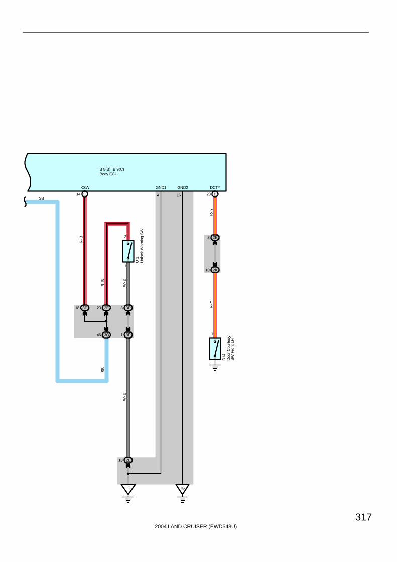
2004 LAND CRUISER (EWD548U)
317
KSW
C
18 3E
46 3Q
23 3E
R-B
1
2
1 3P
3 3P
R-B
U 1
W-B
IF
2E18
IG
W-B
SB
GND2GND1
16414
Unl
ock
War
ning
SW
B23
2E8
2K10
1
R-Y
R-Y
Doo
r C
ourt
esy
SW
Fro
nt L
H
D14
DCTY
SB
B 8(B), B 9(C)Body ECU

2004 LAND CRUISER (EWD548U)
318
Key Reminder
When the driver door is opened with the ignition SW off and ignition key remaining in the key cylinder (Unlock warning SWon), a signal is input from the unlock warning SW to the combination meter TERMINAL 9, the body ECU TERMINAL (C) 14,and from the door courtesy SW front LH to the body ECU TERMINAL (B)23. As a result, the buzzer in the combination metergoes on and warns the driver that the key is remaining in the key cylinder.
D14 Door Courtesy SW Front LH1-Ground : Closed with driver’s door open
: Parts Location
Code See Page Code See Page Code See Page
B8 B 70 C15 70 J14 71
B9 C 70 D14 72 U1 71
: Junction Block and Wire Harness Connector
Code See Page Junction Block and Wire Harness (Connector Location)
2E 28 Dash Wire and Cowl Side J/B LH (Left Kick Panel)
2K 28 Floor No.1 Wire and Cowl Side J/B LH (Left Kick Panel)
2Q 30 Instrument Panel Integration Wire and Cowl Side J/B LH (Left Kick Panel)
3E 40Dash Wire and Cowl Side J/B RH (Right Kick Panel)
3P 43Dash Wire and Cowl Side J/B RH (Right Kick Panel)
3Q 42 Instrument Panel Integration Wire and Cowl Side J/B RH (Right Kick Panel)
: Connector Joining Wire Harness and Wire Harness
Code See Page Joining Wire Harness and Wire Harness (Connector Location)
IX1 82 Instrument Panel Integration Wire and Engine Wire (Behind the Glove Box)
: Ground Points
Code See Page Ground Points Location
EC 76 Rear Bank of Right Cylinder Head
IF78 Set Bolt of Cowl Side J/B LH
IG78 Set Bolt of Cowl Side J/B LH
System Outline
Service Hints
2004 LAND CRUISER (EWD548U)
319
Memo

2004 LAND CRUISER (EWD548U)
320
Seat Belt WarningS
eat
Bel
t
Buzzer
A10 D11 D12
7. 5AMET
3Q7
SB
10AGAUGE1
2Q65
10AECU- B2
3Q44
A
AJ14
SB
SB
SB
D1 C11
IX18 2Q41
2K18
BU13
BM25
3
BM24
BU11
E
E
BJ
B11
BMEC
2G10
13
SB
SB
GG
G
G
W-B
W-B
W-B
W-B
W-B
W-B
BR
B 7
J22
A30
C22
15AA/C
From Power Source System (See Page 94)
2D25
8
3N21
R-L
3N11
R-L
3D26
3K21
BV13
BO25
GG
BK
1
2
3
2
BO24
BV11
S 8
B 6
G
G- WW
-BW
-BW
-B
G G
20
2D6
A45
( A) ,
A47
( C)
C28
( *1)
( *1)
IG IG
I- SBWS/BW
R-L
( *2)
C12(A), C14(C), C15(D)
( *1)
( *2)
DBKL
* 2 : w/o Navigation System* 1 : w/ Navigation System
Buc
kle
SW
RH
Combination Meter
A/C
Con
trol
Ass
embl
y
Body ECU
Cen
ter
Clu
ster
Inte
grat
ion
Pan
el
Junc
tion
Con
nect
or
Junc
tion
Con
nect
or
B 5
Buc
kle
SW
LH
2
1
G
BM23
C25(A), (B)
LBE+
Center AirbagSensor Assembly
B11 (*2)A19 (*1)
G
G
Sea
t Bel
t W
arni
ngO
ccup
ant D
etec
tion
Sen
sor
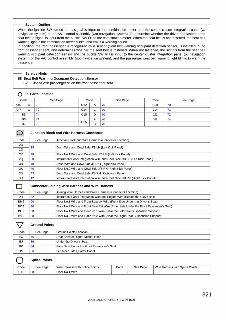
2004 LAND CRUISER (EWD548U)
321
When the ignition SW turned on, a signal is input to the combination meter and the center cluster integration panel (w/navigation system) or the A/C control assembly (w/o navigation system). To determine whether the driver has fastened theseat belt, a signal is input from the buckle SW LH to the combination meter. When the seat belt is not fastened, the seat beltwarning light in the combination meter blinks, and emits a warning sound.In addition, the front passenger is recognized by a sensor (Seat belt warning occupant detection sensor) is installed in thefront passenger seat, and determines whether the seat belt is fastened. When not fastened, the signals from the seat beltwarning occupant detection sensor and the buckle SW RH is input to the center cluster integration panel (w/ navigationsystem) or the A/C control assembly (w/o navigation system), and the passenger seat belt warning light blinks to warn thepassenger.
S8 Seat Belt Warning Occupant Detection Sensor1-2 : Closed with passenger sit on the front passenger seat
: Parts Location
Code See Page Code See Page Code See Page
A45 A 70 C12 A 70 C28 70
A47 C 70 C14 C 70 J14 71
B5 74 C15 D 70 J22 72
B6 74C25
A 70 S8 74
B7 70C25
B 70
: Junction Block and Wire Harness Connector
Code See Page Junction Block and Wire Harness (Connector Location)
2D28 Dash Wire and Cowl Side J/B LH (Left Kick Panel)
2G28 Dash Wire and Cowl Side J/B LH (Left Kick Panel)
2K 28 Floor No.1 Wire and Cowl Side J/B LH (Left Kick Panel)
2Q 30 Instrument Panel Integration Wire and Cowl Side J/B LH (Left Kick Panel)
3D 40 Dash Wire and Cowl Side J/B RH (Right Kick Panel)
3K 40 Floor No.2 Wire and Cowl Side J/B RH (Right Kick Panel)
3N 43 Dash Wire and Cowl Side J/B RH (Right Kick Panel)
3Q 42 Instrument Panel Integration Wire and Cowl Side J/B RH (Right Kick Panel)
: Connector Joining Wire Harness and Wire Harness
Code See Page Joining Wire Harness and Wire Harness (Connector Location)
IX1 82 Instrument Panel Integration Wire and Engine Wire (Behind the Glove Box)
BM2 90 Floor No.1 Wire and Front Seat LH Wire (Front Side Under the Driver’s Seat)
BO2 90 Floor No.2 Wire and Front Seat RH Wire (Front Side Under the Front Passenger’s Seat)
BU1 88 Floor No.1 Wire and Floor No.1 Wire (Near the Left Rear Suspension Support)
BV1 88 Floor No.2 Wire and Floor No.2 Wire (Near the Right Rear Suspension Support)
: Ground Points
Code See Page Ground Points Location
EC 76 Rear Bank of Right Cylinder Head
BJ 86 Under the Driver’s Seat
BK 86 Front Side Under the Front Passenger’s Seat
BM 86 Left Rear Side Quarter Panel
: Splice Points
Code See Page Wire Harness with Splice Points Code See Page Wire Harness with Splice Points
B11 88 Floor No.1 Wire
System Outline
Service Hints
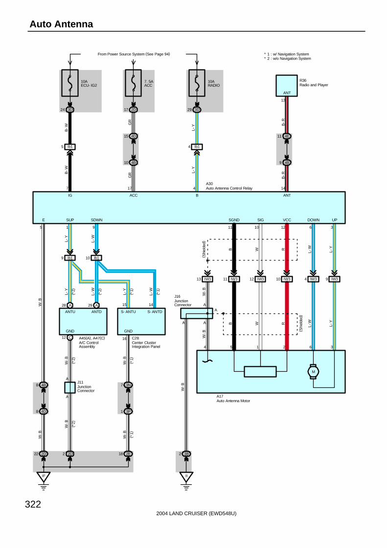
2004 LAND CRUISER (EWD548U)
322
Auto Antenna
M
362154
IW39IW34IW310IW312IW311IW313
36121011
W-B
A
W-B
AA
II
3B2
A28 A29
C12 16
15 14
Ib19 Ib110
IF
2D22 2D2 2E18
3N7
3P1
A
A
4B8
4D8
J16
A
1 95
L-Y
L-W
W-B
W-B
W-B
W-B
W-B
W-B
W-B
B W R
L-W
L-Y
B W R
L-W
L-Y
L-Y
L-W
L-Y
L-W
( *2)
( *2)
( *1)
( *1)
A45(A), A47(C) C28
J11
A17
10AECU- IG2
3D24
7. 5AACC
From Power Source System (See Page 94)
2D17
10ARADIO
3D29
7 17 4
Ib15 Ib14
4D15
4B10
B-W
B-W
GR
GR
L-Y
L-Y
14
4E11
4B9
B-R
B-R
R36
IG ACC B ANT
ANT
A30
E SUP SDWN SGND SIG VCC DOWN UP
(*2)
( *1)
( *2)
( *1)
GND GND
ANTU ANTD S- ANTU S- ANTD
( Shi
elde
d)
( Shi
elde
d)
* 2 : w/o Navigation System* 1 : w/ Navigation System
Auto Antenna Motor
Auto Antenna Control Relay
A/C ControlAssembly
Center ClusterIntegration Panel
JunctionConnector
JunctionConnector
Radio and Player
13

2004 LAND CRUISER (EWD548U)
323
A30 Auto Antenna Control Relay4-Ground : Always approx. 12 volts
17-Ground : Approx. 12 volts with ignition SW at ACC or ON position7-Ground : Approx. 12 volts with ignition SW at ON or ST position5-Ground : Always continuity
: Parts Location
Code See Page Code See Page Code See Page
A17 68 A47 C 70 J16 71
A30 70 C28 70 R36 71
A45 A 70 J11 71
: Junction Block and Wire Harness Connector
Code See Page Junction Block and Wire Harness (Connector Location)
2D28 Dash Wire and Cowl Side J/B LH (Left Kick Panel)
2E28 Dash Wire and Cowl Side J/B LH (Left Kick Panel)
3B 40 Engine Room No.2 Wire and Cowl Side J/B RH (Right Kick Panel)
3D 40
3N43
Dash Wire and Cowl Side J/B RH (Right Kick Panel)
3P43
( g )
4B
4D 52 Dash Wire and J/B No.4 (Instrument Panel Center)
4E
( )
: Connector Joining Wire Harness and Wire Harness
Code See Page Joining Wire Harness and Wire Harness (Connector Location)
IW3 82 Engine Room No.2 Wire and Dash Wire (Behind the Glove Box)
Ib1 84 Dash Wire and Dash Wire (Behind the Combination Meter)
: Ground Points
Code See Page Ground Points Location
IF 78 Set Bolt of Cowl Side J/B LH
II 78 Set Bolt of Cowl Side J/B RH
Service Hints

2004 LAND CRUISER (EWD548U)
324
Radio and Player (w/ Navigation System)
7. 5AACC
2Q2
SB
3Q18
3D33
GR
BF
AH AH
3K9
10ARADIO
From Power Source System (See Page 94)
3D36 3D31 3D14
A1
+B
A11
ACC
10
C14
SGND
IP26
( Shi
elde
d)( S
hiel
ded)
IP25
C15
RSA R+
9R
R
IP27
C16
RSA R-
8
WW
IP23
C17
RSA L+
7
BB
IP24
C18
RSA L-
6
GG
IP28
C19
RMUTE
11
OO
IP217
B6
MUTE
21
WW
IP211 IP29 IP21 IP215 IP214 IP216
AH
J 9(A), J10(B)
24 12 17 19 20 18
GR
L-Y
BR P L W
R39
R36(A), R37(B), R38(C)
Ig136
BR
GR
L-Y P L W
GR
L-Y
L-Y
L-Y
L-Y
BR
GR
W
L
P
GR
GND
RSR-
L- Y
BR
GR
GR
GR
SLD RSR+ RSL+ RSL- RMUT
ACC +B TX+ TX- LMUT
MUTE
GR
JunctionConnector
Rear Seat Audio Controller
Radio and Player
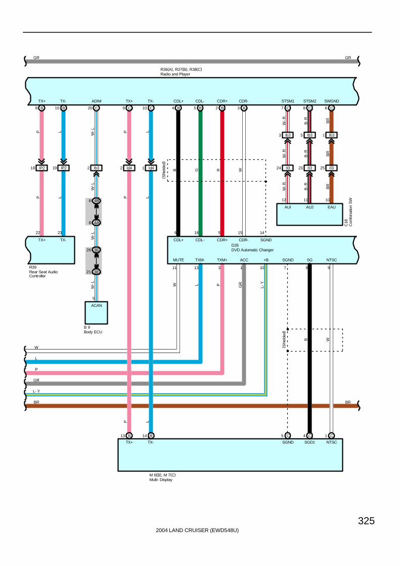
2004 LAND CRUISER (EWD548U)
325
IP218
B9
TX+
22
PP
IP219
B10
TX-
23
LL
R39
C9
TX+
C10
TX-
Id42 Id41
B4
CDL+
B
6
B5
CDL-
G
16
B2
CDR+
R
5
B3
CDR-
W
15 14
( Shi
elde
d)
11 13 3 1 10
GR
W
L
P
GR
W L P GR
L-Y
GR
D26
7 8 9
B W
R36(A), R37(B), R38(C)
L- Y
BR
C7
STSM1
C8
STSM2
C6
SWGND
Ib33
II324
12
W-R
B-R BR
W-R
B-R BR
W-R
Ib35
II323
11
B-R
Ib31
II325
10
BR
AUI AU2 EAU
C18
C1
NTSC
C4
SGD1
C5
SGND
B14
TX-
B13
TX+
M 6(B), M 7(C)
BR
P L
MUTE TXM- TXM+ ACC +B
P L
P L
TX+ TX-
( Shi
elde
d)
SGND SG NTSC
CDL+ CDL- CDR+ CDR- SGND
Com
bina
tion
SW
DVD Automatic Changer
Multi- Display
Rear Seat AudioController
Radio and Player
C20
ADIM
5
W-L
W-L
ACAN
4A8
3E21
4B6
3E26
W-L
W-L
Body ECUB 9
Ib32
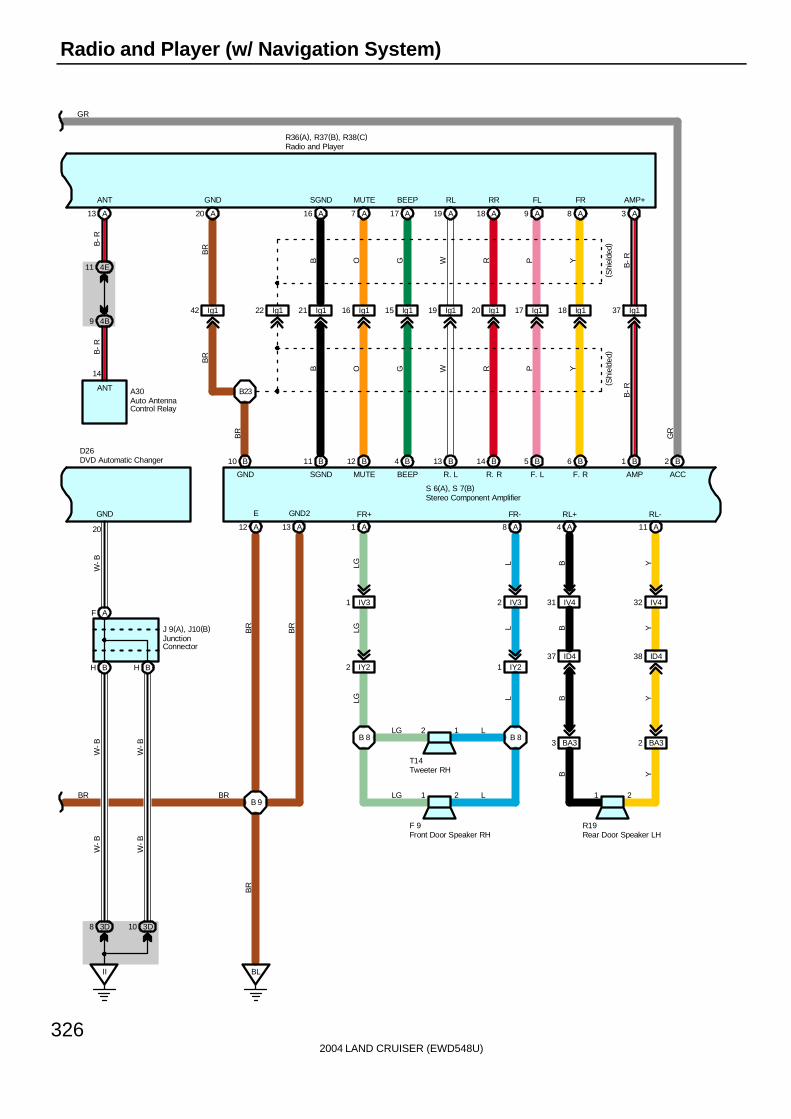
2004 LAND CRUISER (EWD548U)
326
Radio and Player (w/ Navigation System)
20
J 9(A), J10(B)
W-B
BH BH
AF
W-B
II
3D8 3D10
W-B
GR
D26
A12
E
B 9
BL
W-B
W-B
A13
GND2
A1
LG
IV31
LG
IY22
2 1B 8
LG
LG L
1 2
B 8
A8
L
IV32
L
IY21
L
L
T14
LG
FR-FR+ RL+ RL-
2 BA33 BA3
R19
YB
YID4
Y
32 IV4
Y
11 A
21
B
37 ID4
B
31 IV4
B
4 A
38
F 9
A20
GND
B23
BR
BR
42 Ig1 Ig122 Ig121
A16
SGND
BIg116
A7
MUTE
O
Ig115
A17
BEEP
11
G
Ig119
A19
RL
SGND
W
Ig120
A18
RR
B B
R
Ig117
A9
FL
GND
10
P
Ig118
A8
FR
Y
Ig137
A3
AMP+
B-R
( Shi
elde
d)( S
hiel
ded)
A13
ANT
4E11
4B9
A30
14
B-R
B-R
BR
ANT
12
MUTE
B 4
BEEP
B 13
R. L
B 14
R. R
B 5
F. L
B 6
F. R
B 1
AMP
B 2
ACC
B
R36(A), R37(B), R38(C)
S 6(A), S 7(B)
B O G W R P Y
GR
B-R
GND
BR BR
BR
BR
BR
Auto AntennaControl Relay
DVD Automatic Changer
Front Door Speaker RH Rear Door Speaker LH
Stereo Component Amplifier
Tweeter RH
JunctionConnector
Radio and Player
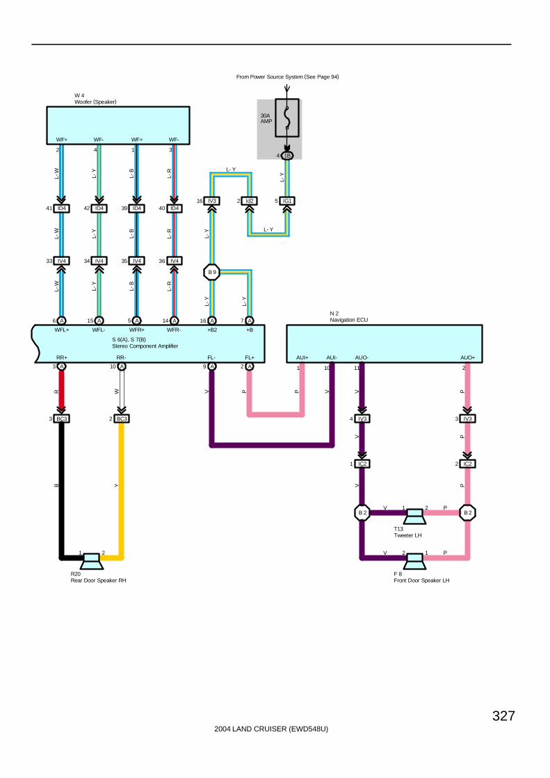
2004 LAND CRUISER (EWD548U)
327
RR+ RR-
R20
Y
2 BC3
W
10 A
21
B
3 BC3
R
3 A
4 IV3
V
WFL+
6 A
IV433
40 ID4
2
L-W
L-W
L-W
WFL-
15 A
IV434
39 ID4
4
L-Y
L-Y
L-Y
WFR+
5 A
IV435
42 ID4
1
L-B
L-B
L-B
WFR-
14 A
IV436
41 ID4
3
L-R
L-R
L-R
A16
+B2
B 9
IV316 Id22 IG15
4 1B
From Power Source System (See Page 94)
30AAMP
A7
+B
W 4
A
V
IC21
1 2B 2
V
V P
2 1
B 2
P
IV33
PIC22
P
P
T13
V
AUO+AUO-
F 8
AUI-AUI+
2
FL+
A9
FL-
PV P V
N 2
S 6(A), S 7(B)
L-Y
L-Y
L-Y
L-Y
L- Y
L- Y
WF+ WF- WF+ WF-
211101
Front Door Speaker LH
Navigation ECU
Rear Door Speaker RH
Stereo Component Amplifier
Tweeter LH
Woofer (Speaker)

2004 LAND CRUISER (EWD548U)
328
Radio and Player (w/ Navigation System)
R36 Radio and Player1-Ground : Always approx. 12 volts
11-Ground : Approx. 12 volts with ignition SW at ACC or ON position
S6 (A), S7 (B) Stereo Component Amplifier(A) 7, (A) 16-Ground : Always approx. 12 volts
(B) 2-Ground : Approx. 12 volts with ignition SW at ACC or ON position(A) 12, (A) 13-Ground : Always continuity
: Parts Location
Code See Page Code See Page Code See Page
A30 70 M6 B 71 R39 71
B9 70 M7 C 71 S6 A 73
C18 70 N2 72 S7 B 73
D26 70 R19 73 T13 73
F8 72 R20 73 T14 73
F9 72 R36 A 71 W4 73
J9 A 71 R37 B 71
J10 B 71 R38 C 71
: Junction Block and Wire Harness Connector
Code See Page Junction Block and Wire Harness (Connector Location)
1B 24 Engine Room No.2 Wire and Engine Room J/B (Engine Compartment Left)
2Q 30 Instrument Panel Integration Wire and Cowl Side J/B LH (Left Kick Panel)
3D40 Dash Wire and Cowl Side J/B RH (Right Kick Panel)
3E40 Dash Wire and Cowl Side J/B RH (Right Kick Panel)
3K 40 Floor No.2 Wire and Cowl Side J/B RH (Right Kick Panel)
3Q 42 Instrument Panel Integration Wire and Cowl Side J/B RH (Right Kick Panel)
4A
4B 52 Dash Wire and J/B No.4 (Instrument Panel Center)
4E
( )
: Connector Joining Wire Harness and Wire Harness
Code See Page Joining Wire Harness and Wire Harness (Connector Location)
IC2 78 Front Door LH Wire and Dash Wire (Left Kick Panel)
ID4 78 Dash Wire and Floor No.1 Wire (Left Kick Panel)
IG1 78 Engine Room No.2 Wire and Dash Wire (Behind the Combination Meter)
II3 80 Dash Wire and Column Wire (Near the Ignition SW)
IP2 80 Rear Console Box Wire and Dash Wire (Right Side of Rear Console)
IV382 Dash Wire and Floor No 2 Wire (Right Kick Panel)
IV482 Dash Wire and Floor No.2 Wire (Right Kick Panel)
IY2 82 Front Door RH Wire and Dash Wire (Right Kick Panel)
Ib3 84 Dash Wire and Dash Wire (Behind the Combination Meter)
Id284 Dash Wire and Dash Wire (Instrument Panel Center)
Id484 Dash Wire and Dash Wire (Instrument Panel Center)
Ig1 84 Dash Wire and Floor No.2 Wire (Right Side of Front Console)
BA3 86 Rear Door LH Wire and Floor No.1 Wire (Left Side of Center Pillar)
BC3 86 Rear Door RH Wire and Floor No.2 Wire (Right Side of Center Pillar)
: Ground Points
Code See Page Ground Points Location
II 78 Set Bolt of Cowl Side J/B RH
BL 86 Rear Side Under the Front Passenger’s Seat
Service Hints
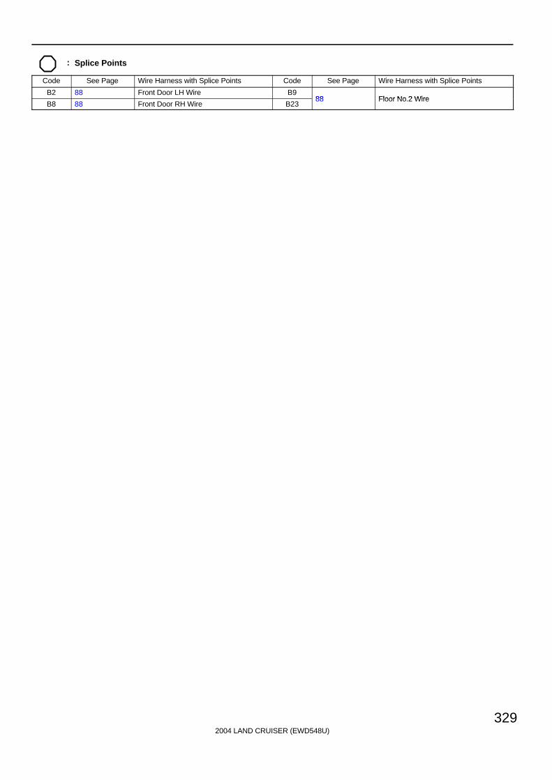
2004 LAND CRUISER (EWD548U)
329
: Splice Points
Code See Page Wire Harness with Splice Points Code See Page Wire Harness with Splice Points
B2 88 Front Door LH Wire B988 Floor No 2 Wire
B8 88 Front Door RH Wire B2388 Floor No.2 Wire

2004 LAND CRUISER (EWD548U)
330
Radio and Player (w/o Navigation System)
7. 5AACC
2Q2
SB
3Q18
3D33
BF
AH AH
GR
J 9(
A) ,
J10(
B)
10ARADIO
From Power Source System (See Page 94)
3D14 3D31
3K9
R39
12
IP29L-
YL-
Y
+B
24
IP211
GR
GR
ACC
10
IP26
( Shi
elde
d)( S
hiel
ded)
SLD
9
IP25
RR
RSR+
8
IP27
WW
RSR-
7
IP23
BB
RSL+
6
IP24
GG
RSL-
C14
SGND
C15
RSA R+
C16
RSA R-
C17
RSA L+
C18
RSA L-
11
IP28
OO
RMUT
C19
RMUTE
GR
A1
BU
A11
ACC
C7
STSM1
C8
STSM2
C6
SWGND
A13
ANT
W-R
B-R BR
Ib33 Ib35 Ib31
W-R
B-R BR
II324 II323 II325
W-R
B-R BR
12 11 10
C18
4E11
4B9
14
B-R
B-R
A30
L-Y
L-Y
L-Y
GR
GR
GR
GR
R36(A), R37(B), R38(C)
AU1 AU2 EAU ANT
Auto AntennaControl RelayCombination SW
Radio and Player
Junc
tion
Con
nect
or
Rear Seat Audio Controller

2004 LAND CRUISER (EWD548U)
331
21
IP217
WW
MUTE
B6
MUTE
22
IP218
PP
TX+
B9
TX+
23
IP219
LL
TX-
B10
TX-
R39
GR
Y
A8
FR
P
A9
FL
R
A18
RR
W
A19
RL
G
A17
BEEP
OA7
MUTE
B
A16
SLD
(Shi
elde
d)
BR
A20
GND
Ig118 Ig117 Ig120 Ig119 Ig115 Ig116 Ig121 Ig142Ig122
17
GND
GR
BR
Y
P
R
W
G
O
B
(Shielded)
BR
BOGWRPY
R36(A), R37(B), R38(C)
BR
A3
AMP
Ig137
B-R
B- R
B-R
Radio and Player
Rear Seat Audio Controller
C20
ADIM
5
W-L
W-L
ACAN
4A8
3E21
4B6
3E26
W-L
W-L
Body ECUB 9
Ib32

2004 LAND CRUISER (EWD548U)
332
Radio and Player (w/o Navigation System)
F. R
B12
MUTESGND
11 B
Y
BR
GR
F. LGND
10 B 5 BB
R. R
14
R. L
13 BB4
BEEP
6 B
B23
P
R
W
G
O
B
BR
(Shielded)
BR
B O G W R P Y
( Shi
elde
d)
ACC
2 B
+B
7 A
5 IG1
30AAMP
From Power Source System(See Page 94)
1B4
GR
L-Y
L-Y
L-Y
L-Y
L- Y
A16
+B2
B 9
IV316 Id22
L- Y
BR
S 6(A), S 7(B)
AMP+
B1
B-R
B- R
A2
P
IV33
P
IC22
2 1B 2
P
P
38
V
1 2
B 2
A9
V
IV34
V
IC21
V
V
T13
P
F 8
A1
LG
IV31
LG
IY22
2 1B 8
LG
LG L
1 2
B 8
A8
L
IV32
L
IY21
L
L
T14
LG
F 9
A4
B
IV431
B
ID437
B
1 2
A11
YIV432
Y
ID4
Y
B Y
R19
BA33 BA32
RL-RL+FR-FR+FL-FL+
Front Door Speaker LH Front Door Speaker RH Rear Door Speaker LH
Stereo Component Amplifier
Tweeter LH Tweeter RH

2004 LAND CRUISER (EWD548U)
333
BR
ID441
IV433
A6
W 4
2
L-W
L-W
L-W
WFL+
WF+
ID442
IV434
A15
4
L-Y
L-Y
L-Y
WFL-
WF-
ID439
IV435
A5
1
L-B
L-B
L-B
WFR+
WF+
ID440
IV436
A14
3
L-R
L-R
L-R
WFR-
WF-
A3
R
BC33
B
12 A
B 9
1 2
A10
W
BC32
IP21
Y
R20
II436
13 A
BL
BR
BR
BR
BR
BR
BR
BR
EGND2RR-RR+
S 6(A), S 7(B)
Rear Door Speaker RH
Stereo Component Amplifier
Woofer (Speaker)
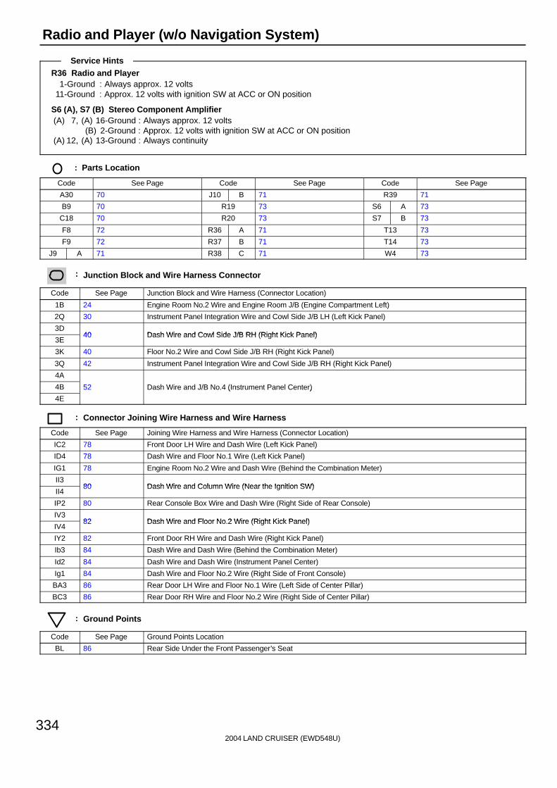
2004 LAND CRUISER (EWD548U)
334
Radio and Player (w/o Navigation System)
R36 Radio and Player1-Ground : Always approx. 12 volts
11-Ground : Approx. 12 volts with ignition SW at ACC or ON position
S6 (A), S7 (B) Stereo Component Amplifier(A) 7, (A) 16-Ground : Always approx. 12 volts
(B) 2-Ground : Approx. 12 volts with ignition SW at ACC or ON position(A) 12, (A) 13-Ground : Always continuity
: Parts Location
Code See Page Code See Page Code See Page
A30 70 J10 B 71 R39 71
B9 70 R19 73 S6 A 73
C18 70 R20 73 S7 B 73
F8 72 R36 A 71 T13 73
F9 72 R37 B 71 T14 73
J9 A 71 R38 C 71 W4 73
: Junction Block and Wire Harness Connector
Code See Page Junction Block and Wire Harness (Connector Location)
1B 24 Engine Room No.2 Wire and Engine Room J/B (Engine Compartment Left)
2Q 30 Instrument Panel Integration Wire and Cowl Side J/B LH (Left Kick Panel)
3D40 Dash Wire and Cowl Side J/B RH (Right Kick Panel)
3E40 Dash Wire and Cowl Side J/B RH (Right Kick Panel)
3K 40 Floor No.2 Wire and Cowl Side J/B RH (Right Kick Panel)
3Q 42 Instrument Panel Integration Wire and Cowl Side J/B RH (Right Kick Panel)
4A
4B 52 Dash Wire and J/B No.4 (Instrument Panel Center)
4E
( )
: Connector Joining Wire Harness and Wire Harness
Code See Page Joining Wire Harness and Wire Harness (Connector Location)
IC2 78 Front Door LH Wire and Dash Wire (Left Kick Panel)
ID4 78 Dash Wire and Floor No.1 Wire (Left Kick Panel)
IG1 78 Engine Room No.2 Wire and Dash Wire (Behind the Combination Meter)
II380 Dash Wire and Column Wire (Near the Ignition SW)
II480 Dash Wire and Column Wire (Near the Ignition SW)
IP2 80 Rear Console Box Wire and Dash Wire (Right Side of Rear Console)
IV382 Dash Wire and Floor No 2 Wire (Right Kick Panel)
IV482 Dash Wire and Floor No.2 Wire (Right Kick Panel)
IY2 82 Front Door RH Wire and Dash Wire (Right Kick Panel)
Ib3 84 Dash Wire and Dash Wire (Behind the Combination Meter)
Id2 84 Dash Wire and Dash Wire (Instrument Panel Center)
Ig1 84 Dash Wire and Floor No.2 Wire (Right Side of Front Console)
BA3 86 Rear Door LH Wire and Floor No.1 Wire (Left Side of Center Pillar)
BC3 86 Rear Door RH Wire and Floor No.2 Wire (Right Side of Center Pillar)
: Ground Points
Code See Page Ground Points Location
BL 86 Rear Side Under the Front Passenger’s Seat
Service Hints

2004 LAND CRUISER (EWD548U)
335
: Splice Points
Code See Page Wire Harness with Splice Points Code See Page Wire Harness with Splice Points
B2 88 Front Door LH Wire B988 Floor No 2 Wire
B8 88 Front Door RH Wire B2388 Floor No.2 Wire
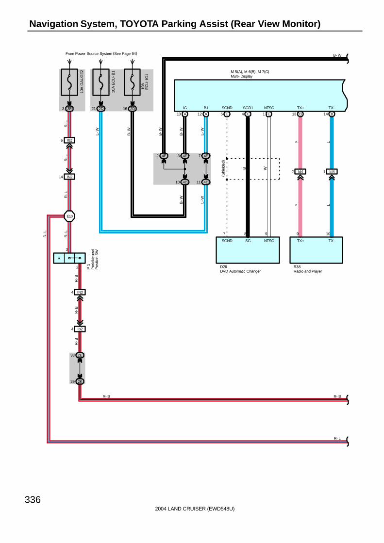
2004 LAND CRUISER (EWD548U)
336
Navigation System, TOYOTA Parking Assist (Rear View Monitor)
A10
IG10
A E
CU
-B1
2D21
10A
EC
U-I
G1
2D16A12
B1
4E3 4E74E2
4D10 4D11B
-W L-W
B-W
B-W
L-W
B-WL-W
B- W
C5
SGND
C4
SGD1
C1
NTSC
7 8 9
(Shi
elde
d)
B W
SGND SG NTSC
B13
TX+
B14
TX-
Id42 Id41
TX-TX+
10A
GA
UG
E2
3E3
Ib26
IN214
R-L
R-L
IN24
Ib24
R-B
R-B
2E38
2K39
R-B
R-L
R- B
From Power Source System (See Page 94)
M 5(A), M 6(B), M 7(C)
D26 R38
P LLP
P 1
9 10
DVD Automatic Changer
Multi- Display
Par
k/N
eutr
alP
ositi
on S
W
Radio and Player
R
3
2
E10
R-L
R-L
R- L
R- B
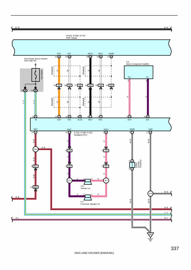
2004 LAND CRUISER (EWD548U)
337
B- W
B21
IVO+
IV425
A12
VOI+
B22
IVO-
IV426
A13
VOI-
IV427
A3
SLD1
B18
MCO+
IV430
C3
MIC+
B19
MCO-
IV428
C5
MIC-
B17
SGND
IV429
4 IV3
V
11 A
V
IC21
1 2B 2
V
V P
2 1
B 2
A2
P
IV33
P
IC22
P
P
T13
V
AUO+AUO-
F 8
A1
AUI+
A10
AUI-
S 6
P V
FL+ FL-
BL16
BD212
A14
REV
R- B
A9
B- W
O W B W
O W B W
( Shi
elde
d)( S
hiel
ded)
M 5(A), M 6(B), M 7(C)R
-BR
-BR
-B
N 2(A), N 3(B), N 4(C)
2 9
Front Door Speaker LH
Multi- Display
Navigation ECU
Stereo Component Amplifier
Tweeter LH
R- L R- L
( Shi
elde
d)( S
hiel
ded)
GND
17 A
SNSE
7 CW
-B
W-B
BK
AD
AD
W-B
W-B
Junc
tion
Con
nect
or
J25(
A)
W- B
B14
16 3K
10A
RA
DIO
L-Y
From Power Source System(See Page 94)
+B
3K8
L-Y
R- B
R- B
L- Y
B 9
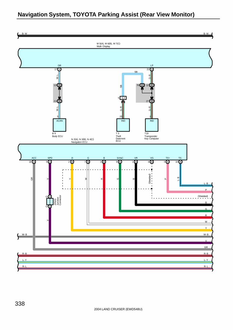
2004 LAND CRUISER (EWD548U)
338
Navigation System, TOYOTA Parking Assist (Rear View Monitor)
( Shi
elde
d)
BG
A17
DR
W-L
3D13
3E21
5
W-L
B 9
ACAN
Body ECU
A21
LP
3D12
3E27
G-R
25
T 5
IL35
3Q76
3
T19
SB
G-R
G-R
SB
IND IND
TheftDeterrentECU
TransponderKey Computer
Y W R
R- LR- L
VGR
A18
ACC
A5
SPD
Multi- Display
B- W
M 5(A), M 6(B), M 7(C)
L-BP
P
L- B
B5
TX+
B10
TX-
B- W
Y
W
B
(Shielded)
R
G
B1
VR
B6
VGSYNC
8 BB2
R B
3 B
G
7 B
GR
V
W- BW- B
Navigation ECUN 2(A), N 3(B), N 4(C)
AG
AG
Junc
tion
Con
nect
or
J25(
A)
V
R- B
L- Y L- Y
R- B
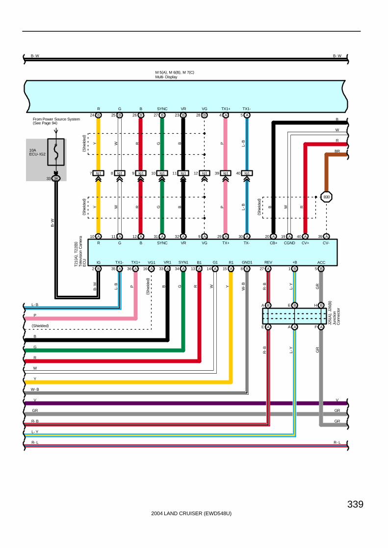
2004 LAND CRUISER (EWD548U)
339
A33
VR1
A34
SYN1VG1
16 A
B- W
B2
IG TX1+
36 A
TX1-
35 A
M 5(A), M 6(B), M 7(C)
B- W
Multi- Display
R- L R- L
GR
V
B
26 B
A
( Shi
elde
d)( S
hiel
ded)
WY
WY
9 Ig1
G
11 A
8 Ig1
G
25 B
R
10 A
7 Ig1
R
24 B B27
SYNC
Ig110
A31
SYNC
B23
VR
Ig111
A32
VR
B28
VG
Ig112
G B
G B
A4
TX1+
Ig139
A29
TX+
A5
TX1-
Ig140
A30
TX-
P L-B
P L-B
GR
V
P
L- B
Y
W
B
(Shielded)
R
G
A13
B1 G1
14 A B1
+B
GR
GR
H B
A15
R1 REV
27 A
GND1
8 B
F
From Power Source System(See Page 94)
3K33
B-W
B-W L-
B P
( Shi
elde
d)
B G R W Y
W-B
A
GR
B5
ACC
AE
BA
AA
BE
R-B
L-Y
W- B
Tele
visi
on C
amer
aE
CU
T21(
A) ,
T22(
B)
12
B
RR
A9
VG
A
( Shi
elde
d)
A19
CGND
A40
CV+
W R
20
CB+
B
A39
CV-
BR
R
W
B
Junc
tion
Con
nect
or
J25(
A) ,
J26(
B)
10AECU- IG2
L- Y
R- B
R-B
L-Y
B30

2004 LAND CRUISER (EWD548U)
340
Navigation System, TOYOTA Parking Assist (Rear View Monitor)
V
GR
B- W
V
GR
M 5(A), M 6(B), M 7(C)
B- W
Multi- Display
R- LR- L
1 BZ1 BZ14 BZ13 BZ12
BY12 BY13 BY11 4 BY1
BH18 BH17 BH19 BH16
R W B
( Shi
elde
d)
R W B
BR R W B
BR
CV-
1
BR
R
W
B
CV+
2
CGND
3
CB+
4
Television CameraT20
GR GR
IF
2E10
W-B
IE26 IE24 IE25 IE23
MACC
Y-G
W-B
Y-G W B
6 B
( Shi
elde
d)
TACC
11
MIC-
2
MIC+
3
Overhead J/BO 5
2L11
B5
MIN-
B4
MIN+
B
( Shi
elde
d)
W B
3
SGND
BE
AA
JunctionConnector
J 9(A), J10(B)
W-B
( Shi
elde
d)( S
hiel
ded)
( Shi
elde
d)
B29
B 7
( Shi
elde
d)( S
hiel
ded)
W-B
W-B
B31
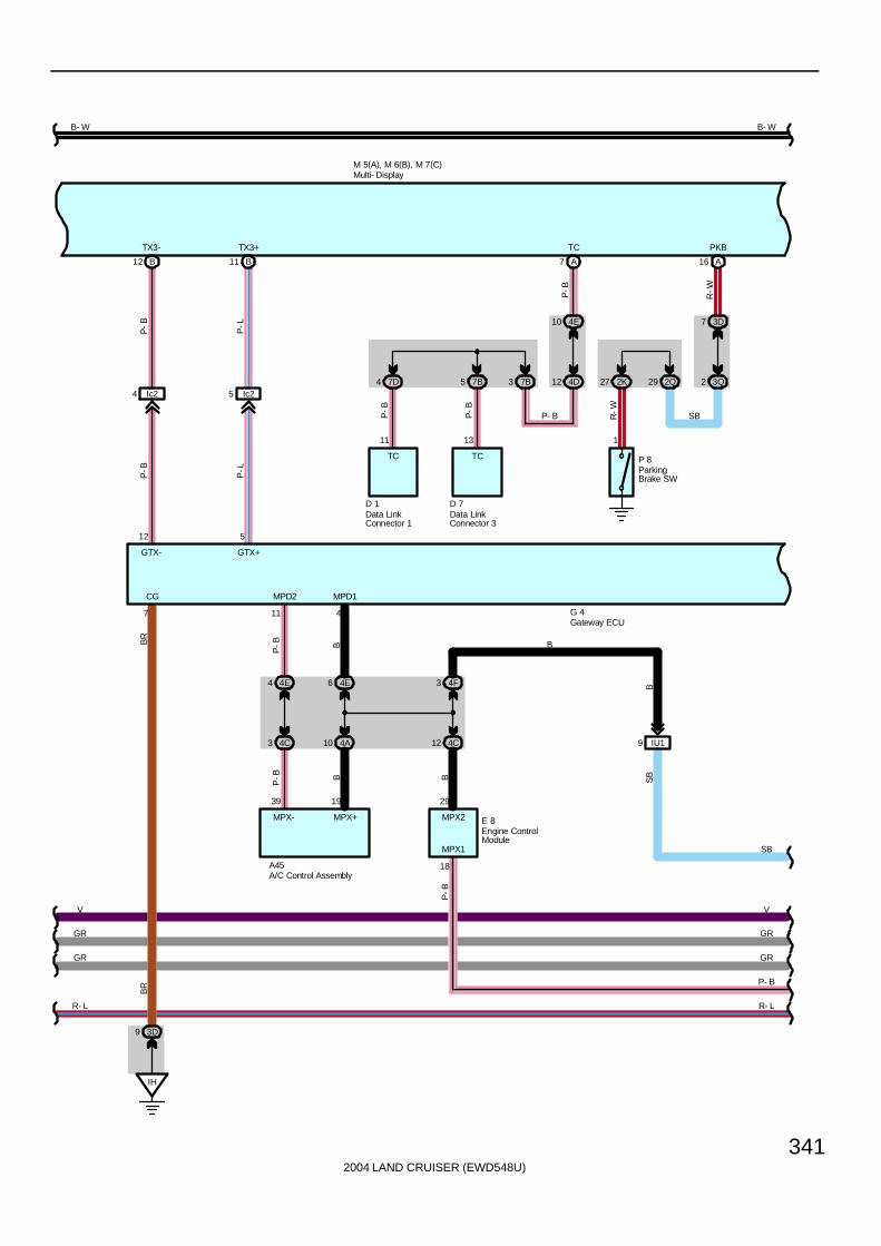
2004 LAND CRUISER (EWD548U)
341
ParkingBrake SW
Data LinkConnector 3
Data LinkConnector 1
R-W
TCTC
SBP- BP-B
P-B
P 8
1
27 2K 29 2Q 2 3Q
7 3D
R-W
PKB
16 A
D 7
13
5 7B
D 1
11
4 7D 3 7B 12 4D
10 4E
P-B
TC
7 AB12
TX3-
12
B11
TX3+
5
IH
3D9
7 11 4
4E4 4E6
4A104C3
P-B B
P-B B
39 19
4F3
4C12 IU19
29
18
SB
P- B
G 4
P-B
B
BB
SB
A45
E 8
BR
GTX- GTX+
CG MPD2 MPD1
BR
MPX- MPX+ MPX2
MPX1
Engine ControlModule
Gateway ECU
A/C Control Assembly
Ic24 Ic25
P-B
P-L
P-B
P-L
B- W
M 5(A), M 6(B), M 7(C)
B- W
Multi- Display
V
GR
V
GR
GR GR
R- LR- L

2004 LAND CRUISER (EWD548U)
342
Navigation System, TOYOTA Parking Assist (Rear View Monitor)
VV
2
A11
ACC
A3
GND1
BH BH BH BH
II
3D103D8
2 2Q 2Q57
3Q18
GR
J 9(
A) ,
J10
( B)
L-W
GR
3D33
BF BF
AH
A25
SPD
10AECU- B2
From Power Source System (See Page 94)
3Q71
2Q22
2E19
4A9
4E5
44 3Q
SB
SB
SB
SB
SB
L-W
SB
3K2
GR
GR
L-W
GR
W-B
W-B
W-B
W-B
W-B
W-B
W-B
B-W
W-BGRV
B- W
GR
SB
P- B
J10(B)
M 5(A), M 6(B), M 7(C)
9 8
14
G 4
V
SB
P- B
IG GND
BATTACC
Gateway ECU
Multi- Display
Junc
tion
Con
nect
or
Junction Connector
7. 5AACC
R- L R- L
GR
3K17
GR

2004 LAND CRUISER (EWD548U)
343
R- L
11 EB1
1
R-L
65 2Q
From Power Source System (See Page 94)
10AGAUGE1
19
Spe
edom
eter
116 15
SB
SB
6 IX1 IX18
BR
EB19
EC
EB110
R-G
R-G BR
BR
R-GBR
12 11
13
A
A
2 320
SB
B
2Q66
2E24
B
3Q43
SB
11
3D
3K
32
V
V
V
V
SB
P- B
SB
SB
SB
SB
SB
SB
J14
SB
P-B
C15
SB
Combination Meter
JunctionConnector
Junc
tion
Con
nect
or
J14
BR
Vehicle Speed Sensor(Combination Meter)
V 2

2004 LAND CRUISER (EWD548U)
344
Navigation System, TOYOTA Parking Assist (Rear View Monitor)
The navigation system displays the operating status and instructions for the automatic air conditioning or radio and player,as well as trip information. Additionally, the navigation system precisely measures the current vehicle position, displays themap obtained from the map database on the screen, and informs the route to the destination shown on the map using voiceguidance.
N2 (A), N4 (C) Navigation ECU(A) 9-Ground : Always approx. 12 volts(A)18-Ground : Approx. 12 volts with ignition SW at ACC or ON position(A)17-Ground : Always continuity(C) 7-Ground : Always continuity
M5 (A), M6 (B) Multi-Display(A)12-Ground : Always approx. 12 volts(A)11-Ground : Approx. 12 volts with ignition SW at ACC or ON position(A)10-Ground : Approx. 12 volts with ignition SW at ON or ST position(A) 3-Ground : Always continuity(B) 3-Ground : Always continuity
T22 Television Camera ECU1-Ground : Always approx. 12 volts5-Ground : Approx. 12 volts with ignition SW at ACC or ON position2-Ground : Approx. 12 volts with ignition SW at ON or ST position8-Ground : Always continuity
: Parts Location
Code See Page Code See Page Code See Page
A45 70 J14 71 P8 73
B9 70 J25 A 72 R38 71
C15 70 J26 B 72 S6 73
D1 68 M5 A 71 T5 71
D7 70 M6 B 71 T13 73
D26 70 M7 C 71 T19 71
E8 70 N2 A 72 T20 73
F8 72 N3 B 72 T21 A 73
G4 70 N4 C 72 T22 B 73
J9 A 71 O5 72 V2 69
J10 B 71 P1 69
System Outline
Service Hints

2004 LAND CRUISER (EWD548U)
345
: Junction Block and Wire Harness Connector
Code See Page Junction Block and Wire Harness (Connector Location)
2D28 Dash Wire and Cowl Side J/B LH (Left Kick Panel)
2E28 Dash Wire and Cowl Side J/B LH (Left Kick Panel)
2K 28 Floor No.1 Wire and Cowl Side J/B LH (Left Kick Panel)
2L 28 Roof No.1 Wire and Cowl Side J/B LH (Left Kick Panel)
2Q 30 Instrument Panel Integration Wire and Cowl Side J/B LH (Left Kick Panel)
3D40 Dash Wire and Cowl Side J/B RH (Right Kick Panel)
3E40 Dash Wire and Cowl Side J/B RH (Right Kick Panel)
3K 40 Floor No.2 Wire and Cowl Side J/B RH (Right Kick Panel)
3Q 42 Instrument Panel Integration Wire and Cowl Side J/B RH (Right Kick Panel)
4A
4C
4D 52 Dash Wire and J/B No.4 (Instrument Panel Center)
4E
( )
4F
7B 64 Dash Wire and J/B No.7 (Behind the Grove Box)
7D 64 Engine Room No.2 Wire and J/B No.7 (Behind the Grove Box)
: Connector Joining Wire Harness and Wire Harness
Code See Page Joining Wire Harness and Wire Harness (Connector Location)
EB1 76 Engine Wire and Transmission Wire (On the Transmission)
IC2 78 Front Door LH Wire and Dash Wire (Left Kick Panel)
IE2 78 Dash Wire and Roof No.1 Wire (Left Kick Panel)
IL3 80 Instrument Panel Integration Wire and Computer Wire (Instrument Panel Center)
IN2 80 Engine Wire and Dash Wire (Behind the Glove Box)
IU1 82 Instrument Panel Integration Wire and Dash Wire (Behind the Glove Box)
IV382 Dash Wire and Floor No 2 Wire (Right Kick Panel)
IV482 Dash Wire and Floor No.2 Wire (Right Kick Panel)
IX1 82 Instrument Panel Integration Wire and Engine Wire (Behind the Glove Box)
Ib2 84 Dash Wire and Dash Wire (Behind the Combination Meter)
Ic2 84 Dash Wire and Dash Wire (Behind the Center Panel)
Id4 84 Dash Wire and Dash Wire (Instrument Panel Center)
Ig1 84 Dash Wire and Floor No.2 Wire (Right Side of Front Console)
BD2 86 Floor No.3 Wire and Floor No.1 Wire (Left Rear Side Quarter Panel)
BH1 86 Pillar No.1 Wire and Back Door Upper Wire (Left Side of Back Door)
BL1 88 Floor No.2 Wire and Floor No.3 Wire (Right Side of Rear Floor Crossmember)
BY1 88 Pillar No.1 Wire and Floor No.3 Wire (Left Rear Side Quarter Panel)
BZ1 88 Floor No.3 Wire and Floor No.2 Wire (Right Side of Rear Floor Crossmember)
: Ground Points
Code See Page Ground Points Location
EC 76 Rear Bank of Right Cylinder Head
IF 78 Set Bolt of Cowl Side J/B LH
IH78 Set Bolt of Cowl Side J/B RH
II78 Set Bolt of Cowl Side J/B RH
BK 86 Front Side Under the Front Passenger’s Seat
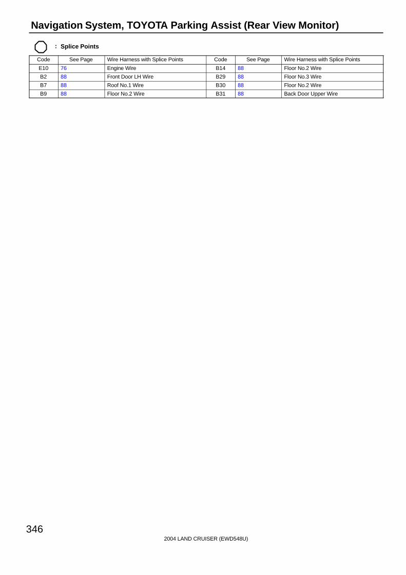
2004 LAND CRUISER (EWD548U)
346
Navigation System, TOYOTA Parking Assist (Rear View Monitor)
: Splice Points
Code See Page Wire Harness with Splice Points Code See Page Wire Harness with Splice Points
E10 76 Engine Wire B14 88 Floor No.2 Wire
B2 88 Front Door LH Wire B29 88 Floor No.3 Wire
B7 88 Roof No.1 Wire B30 88 Floor No.2 Wire
B9 88 Floor No.2 Wire B31 88 Back Door Upper Wire

2004 LAND CRUISER (EWD548U)
347
Memo

2004 LAND CRUISER (EWD548U)
348
Multi-Display (w/o Navigation System)
11
B-W
4E3
4D10
10AECU- IG1
2D16
B-W
AH
BF
3D33
3Q18
7. 5AACC
From Power Source System (See Page 94)
2Q2
10
GR
GR
SB
9
L-W
4E7
4D11
21 2D
10AECU- B1
L-W
4E1
4A16
1
16
A47
J 9(A), J10(B)
M 9
1
Ie14
G-W
G-W
IU46
SB
17
2
Ie13
G-B
G-B
IU47
SB
16
3D13
3E21
3
5
W-L
W-L
3D12
3Q76
14
25
SB
G-R
3E27
3
G-RIL35
G-R
C14 B 9 T 5 T19
II
3D103D8
8
W-B
W-B
W-B
J10(B)
P-L
P-L
IG ACC +B A/C TEMP
TAMO2
UART+ UART- TC SECURITY GND
ACAN IND IND
Combination Meter
Multi- Display
Theft DeterrentECU
A/C ControlAssembly
Body ECU TransponderKey Computer
JunctionConnector
JunctionConnector
BH
BH
BH
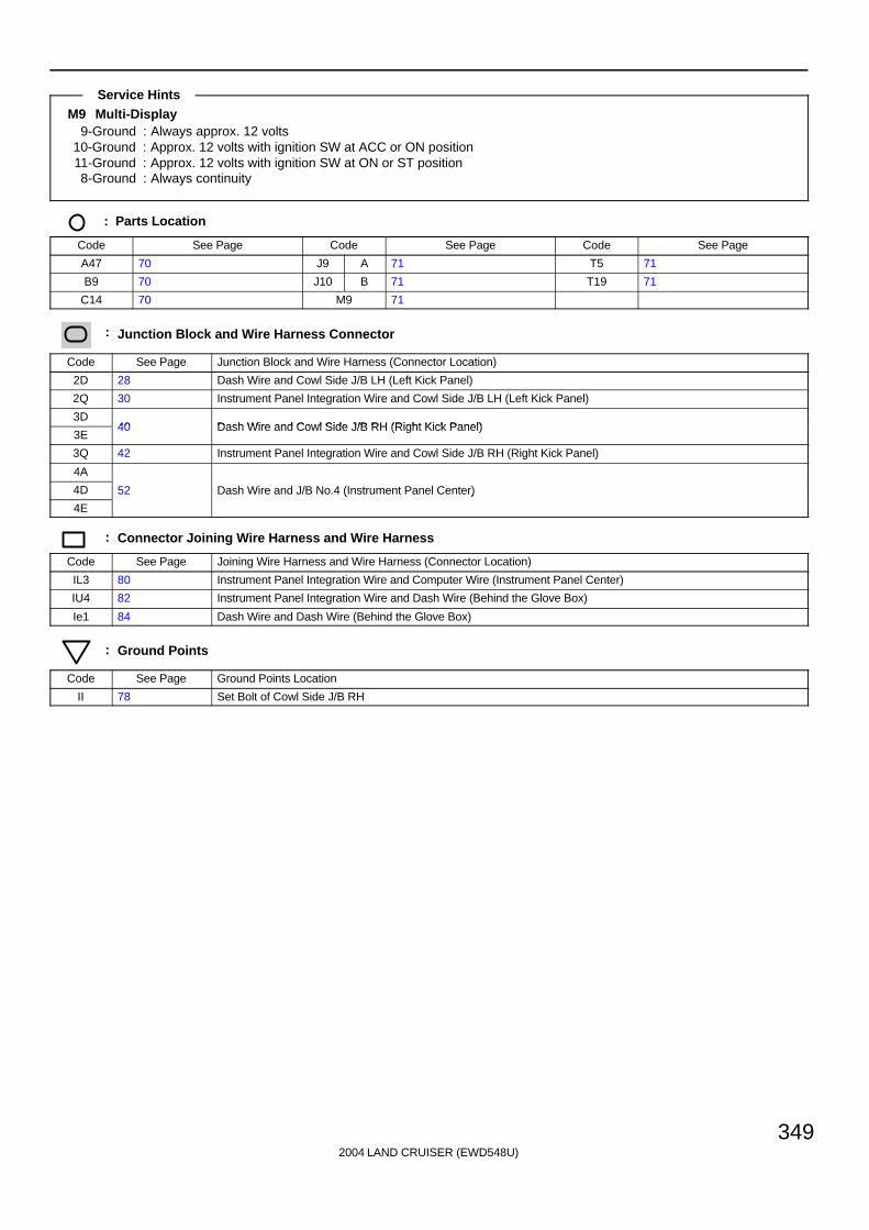
2004 LAND CRUISER (EWD548U)
349
M9 Multi-Display9-Ground : Always approx. 12 volts
10-Ground : Approx. 12 volts with ignition SW at ACC or ON position11-Ground : Approx. 12 volts with ignition SW at ON or ST position8-Ground : Always continuity
: Parts Location
Code See Page Code See Page Code See Page
A47 70 J9 A 71 T5 71
B9 70 J10 B 71 T19 71
C14 70 M9 71
: Junction Block and Wire Harness Connector
Code See Page Junction Block and Wire Harness (Connector Location)
2D 28 Dash Wire and Cowl Side J/B LH (Left Kick Panel)
2Q 30 Instrument Panel Integration Wire and Cowl Side J/B LH (Left Kick Panel)
3D40 Dash Wire and Cowl Side J/B RH (Right Kick Panel)
3E40 Dash Wire and Cowl Side J/B RH (Right Kick Panel)
3Q 42 Instrument Panel Integration Wire and Cowl Side J/B RH (Right Kick Panel)
4A
4D 52 Dash Wire and J/B No.4 (Instrument Panel Center)
4E
( )
: Connector Joining Wire Harness and Wire Harness
Code See Page Joining Wire Harness and Wire Harness (Connector Location)
IL3 80 Instrument Panel Integration Wire and Computer Wire (Instrument Panel Center)
IU4 82 Instrument Panel Integration Wire and Dash Wire (Behind the Glove Box)
Ie1 84 Dash Wire and Dash Wire (Behind the Glove Box)
: Ground Points
Code See Page Ground Points Location
II 78 Set Bolt of Cowl Side J/B RH
Service Hints
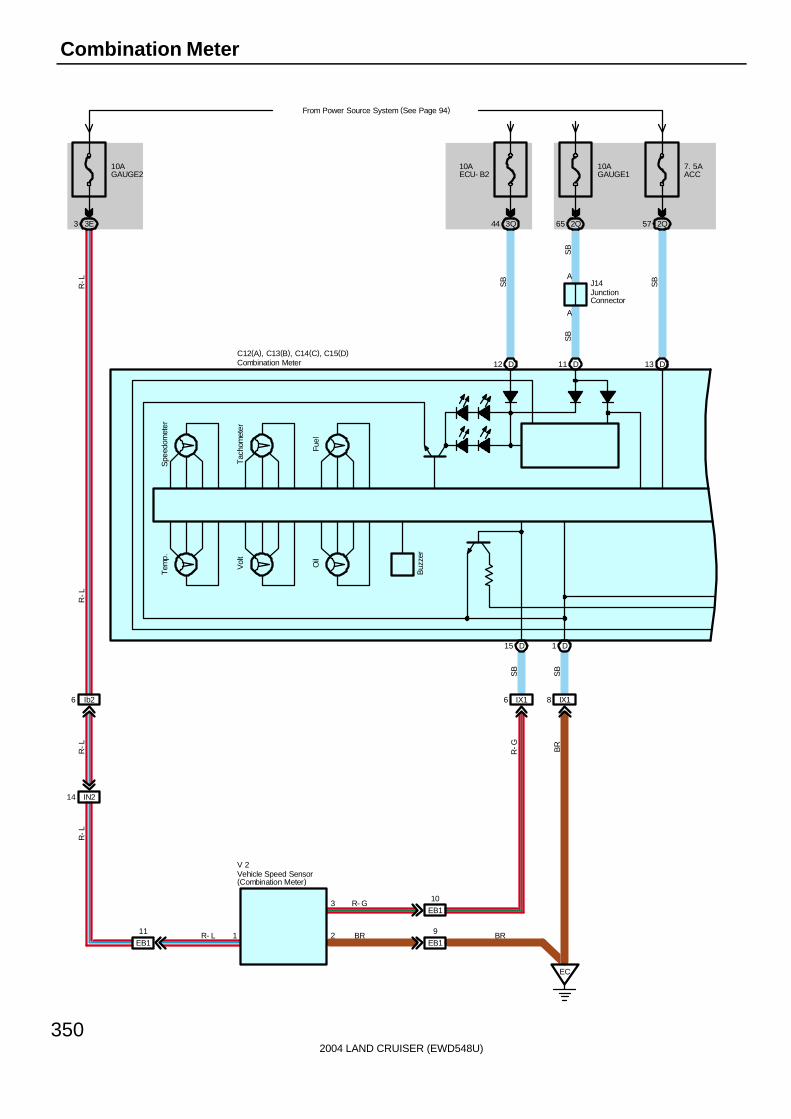
2004 LAND CRUISER (EWD548U)
350
Combination Meter
Vol
tT
acho
met
er
Fuel
Spe
edom
eter
Tem
p.
Oil
Buz
zer
D12 D11 D13
D15 D1
10AECU- B2
3Q44
A
A
10AGAUGE1
From Power Source System (See Page 94)
2Q65
7. 5AACC
2Q57
SB
SB
SB
SBJ14
SB
SB
10AGAUGE2
3E3
IX16 IX18
BR
EC
IN214
Ib26
R-G
R-L
R-L
R-L
R-L
R- L
R- G
BR1
3
2
V 2
C12(A), C13(B), C14(C), C15(D)Combination Meter
Vehicle Speed Sensor(Combination Meter)
JunctionConnector
EB1
10
EB1
9
EB1
11 BR

2004 LAND CRUISER (EWD548U)
351
Sea
t B
elt
P R N 234D
D4 D6 D2
SB
SB
SB
2Q63 2Q62 2Q61
2K19 2K21 2K13
Y-B
Y-R
Y-G
BB15 BB11 BB16
312
Y-B
Y-R
Y-G
F12
D9
Unl
ock
War
ning
SW
SB
A10
7. 5AMET
From Power Source System (See Page 94)
3Q7
SB
L
A/T
P
CR
UIS
E
2nd
ST
RT
EC
T P
WR
D20 D19
SB
SB
2Q66 4F3
2E24 4C12
P-B B
IU19
B
4E6 4E4
4A10 4C3
B P-B
P-B B
18 29 11 4
P- B
B
(*1)
(*1)
( *1)
( *1)
( *1)
( *1)
E 8 A45(A), A47(C) G 4
* 1 : w/ Navigation System
C12(A), C13(B), C14(C), C15(D)
MPX1 MPX2 MPX+ MPX- MPD2 MPD1
Combination Meter
Engine ControlModule
Gateway ECUA/C ControlAssembly
A19 A39
C6
SPDSPD
V
V
17
V
V
Fuel Sender

2004 LAND CRUISER (EWD548U)
352
Combination Meter
SR
S
Fuel
Cha
rge
A/T
OIL
TEM
P
C11
SB
D7
SB
C4
SB
C7
IX29
SB
E
E
SB
D
D
EC
( Shi
elde
d)
W
J17
J12
O 2
C17 C16
SB
SB
IU46 IU47
G-W
G-B
4 Ie1 Ie13
1 2
G-W
G-B
M 9
BR
C12(A), C13(B), C14(C), C15(D)
Cen
ter
Airb
ag S
enso
r A
ssem
bly
Rhe
osta
t
Buc
kle
SW
LH
UART-UART+
(*2)
( *2)
( *2)
( *2)
( *2)
( *2)
Combination Meter
Multi- Display
Oil PressureSender
JunctionConnector
JunctionConnector
V
V
V
V
1
MA
INT
RE
QD
Hea
t Wire
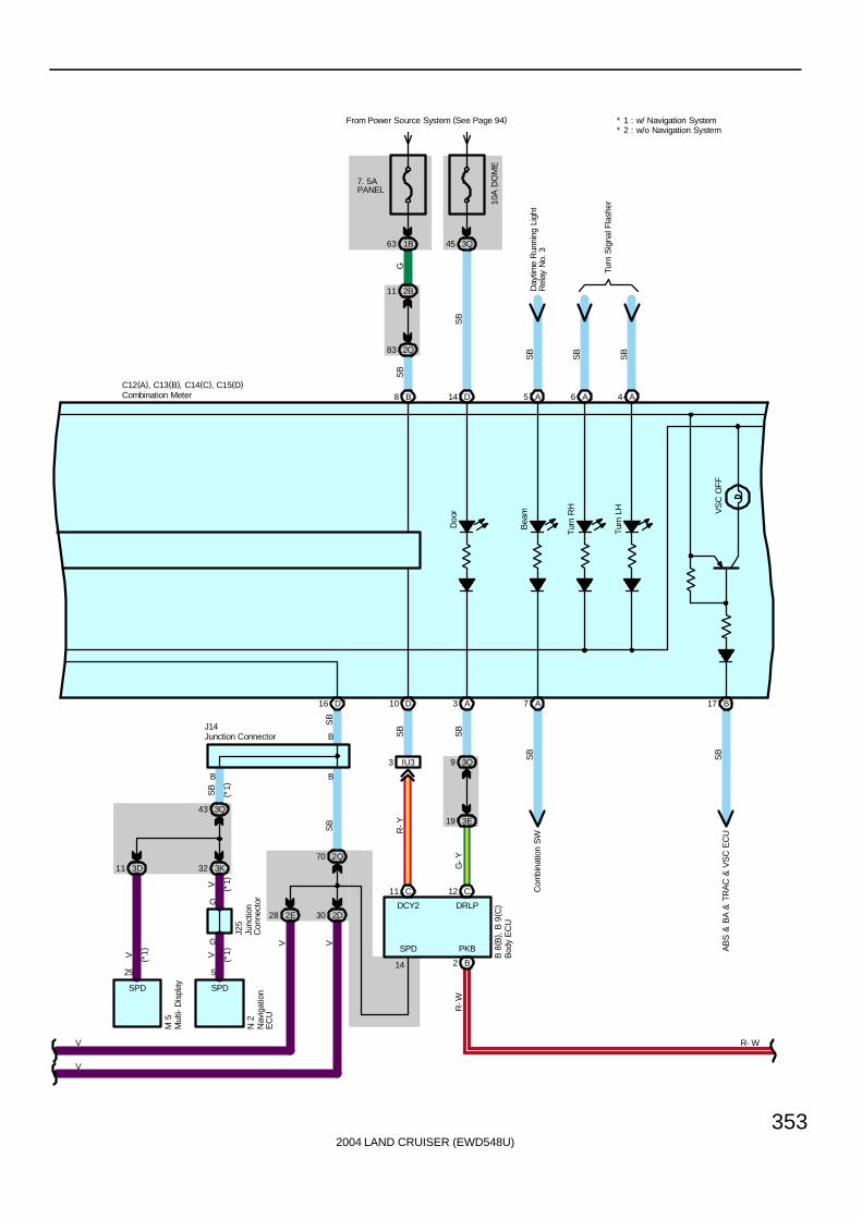
2004 LAND CRUISER (EWD548U)
353
D16
SB
2Q70
B
B
SB
2D302E28
V V
Doo
r
Bea
m
SPD PKB
DRLPDCY2
19 3E
D14 A5B8
10A
DO
ME
3Q45
SB
SB
2Q83
2B11
7. 5APANEL
From Power Source System (See Page 94)
1B63
G
Day
time
Run
ning
Lig
htR
elay
No.
3S
B
3Q43
B
SB
3K323D11
V V
14
D10 A3
SB
SB
IU33
R-Y
G-Y
C11 C12
B2
A7
B 8
( B) ,
B 9
( C)
Turn
RH
Turn
LH VS
C O
FF
6 A A4
Turn
Sig
nal F
lash
er
B17
SB
SB
AB
S &
BA
& T
RA
C &
VS
C E
CU
R- W
R-W
J14
C12(A), C13(B), C14(C), C15(D)
9 3Q
(*1)
* 2 : w/o Navigation System* 1 : w/ Navigation System
Com
bina
tion
SW
SB
SB
Combination Meter
Bod
y E
CU
Junction Connector
( *1)
25 5
SPD SPD
V
V
(*1)
Nav
igat
ion
EC
U
N 2
Mul
ti-D
ispl
ayM
5
G
G
V ( *1)
Junc
tion
Con
nect
or
J25

2004 LAND CRUISER (EWD548U)
354
Combination Meter
2Q37
2E14
Mal
func
tion
Indi
cato
r La
mp
Slip
Cen
ter
Diff
. L
ock
TRA
C
AB
S
BR
AK
E
RS
CA
OF
F
VS
C T
RA
C
B16 B14 B11 B15 B18 A12 C19 C20 C1 C18 B19 B9
IF
2E34
IU22
B
B
1
2Q31
2K27
SB
SB
SB
W-B
R-W
R-W
W-B
SB
SB
SB
SB
SB
SB
SB
SB
SB
Cen
ter
Airb
agS
enso
r A
ssem
bly
P 8
J 8
AB
S &
BA
& T
RA
C &
VS
C E
CU
Det
ectio
n S
W( C
ente
r D
iff.
Lock
)
Eng
ine
Con
trol
Mod
ule
AB
S &
BA
& T
RA
C &
V
SC
Act
uato
r
ABS & BA & TRAC & VSC ECU
R- W
C12(A), C13(B), C14(C), C15(D)Combination Meter
Par
king
Bra
keS
W
Junc
tion
Con
nect
or

2004 LAND CRUISER (EWD548U)
355
P8 Parking Brake SW1-Ground : Closed with parking brake lever pulled up
C12 (A), C13 (B), C15 (D) Combination Meter(D)12, (D) 14-Ground : Always approx. 12 volts
(D) 13-Ground : Approx. 12 volts with ignition SW at ACC or ON position(A) 10, (D) 11-Ground : Approx. 12 volts with ignition SW at ON or ST position
(B) 8-Ground : Approx. 12 volts with light control SW at TAIL or HEAD position(B) 9, (D) 1-Ground : Always continuity
: Parts Location
Code See Page Code See Page Code See Page
A45 A 70 E8 70 M5 71
A47 C 70 F12 72 M9 71
B8 B 70 G4 70 N2 72
B9 C 70 J8 71 O2 69
C12 A 70 J12 71 P8 73
C13 B 70 J14 71 V2 69
C14 C 70 J17 71
C15 D 70 J25 72
: Junction Block and Wire Harness Connector
Code See Page Junction Block and Wire Harness (Connector Location)
1B 24 Engine Room No.2 Wire and Engine Room J/B (Engine Compartment Left)
2B 28 Engine Room No.2 Wire and Cowl Side J/B LH (Left Kick Panel)
2D28 Dash Wire and Cowl Side J/B LH (Left Kick Panel)
2E28 Dash Wire and Cowl Side J/B LH (Left Kick Panel)
2K 28 Floor No.1 Wire and Cowl Side J/B LH (Left Kick Panel)
2Q 30 Instrument Panel Integration Wire and Cowl Side J/B LH (Left Kick Panel)
3D40 Dash Wire and Cowl Side J/B RH (Right Kick Panel)
3E40 Dash Wire and Cowl Side J/B RH (Right Kick Panel)
3K 40 Floor No.2 Wire and Cowl Side J/B RH (Right Kick Panel)
3Q 42 Instrument Panel Integration Wire and Cowl Side J/B RH (Right Kick Panel)
4A
4C52 Dash Wire and J/B No 4 (Instrument Panel Center)
4E52 Dash Wire and J/B No.4 (Instrument Panel Center)
4F
: Connector Joining Wire Harness and Wire Harness
Code See Page Joining Wire Harness and Wire Harness (Connector Location)
EB1 76 Engine Wire and Transmission Wire (On the Transmission)
IN2 80 Engine Wire and Dash Wire (Behind the Glove Box)
IU1
IU282 Instrument Panel Integration Wire and Dash Wire (Behind the Glove Box)
IU382 Instrument Panel Integration Wire and Dash Wire (Behind the Glove Box)
IU4
IX182 Instrument Panel Integration Wire and Engine Wire (Behind the Glove Box)
IX282 Instrument Panel Integration Wire and Engine Wire (Behind the Glove Box)
Ib2 84 Dash Wire and Dash Wire (Behind the Combination Meter)
Ie1 84 Dash Wire and Dash Wire (Behind the Glove Box)
BB1 86 Floor No.1 Wire and Fuel Tank Wire (Near the Fuel Tank)
: Ground Points
Code See Page Ground Points Location
EC 76 Rear Bank of Right Cylinder Head
IF 78 Set Bolt of Cowl Side J/B LH
Service Hints

2004 LAND CRUISER (EWD548U)
356
Air Conditioning (Front)
A45(A), A46(B), A47(C)
A27
DEFC
17 4D
4C5
R-L
( *2)
10AGAUGE1
From Power Source System(See Page 94)
2D19
R-L
A38
BLK
L
5
A37
STX
6
L-B
A36
CLK
7
L-R
A35
DPD
18
L-Y
A34
SWD
19
L-O
( *1)
( *1)
( *1)
( *1)
( *1)
2 16 8
DEFC GND IG
BLK STX CLK DPD SWD
(*2)
R- L
15AA/C
From Power Source System(See Page 94)
2A72D6
C22
IG
R-L
R-L
E16
140A
ALT
50A
HTR
L-B
3 2
4
5 1
11
1 11
EA
56 1B
1A43
II
3H2
IG52
1
2
W-B
L-R
L-R
R-L
R-L
3
IF
2E18
Battery
F18
W-B
B 1
W-R
W- R
R- L
Y- R
R- L(*1)
L- B
W-B
W-BW
-B
R-L
W-B
R-L
R-L
1A34
W-B
W- B
( *1)
( *1)
( *1)
( *1)
( *1)
3P1
3N7
W-B
( *1)
HTRRelay
Y-R
C28
1
Blower MotorController
A/C Control Assembly
Center ClusterIntegration Panel
FusibleLink Block

2004 LAND CRUISER (EWD548U)
357
1B16
1B26 1B8
A23
FRBLW
4C1
W-R
4F9
A9
FRHR
2D29
Y-R
2A15
5A10
5D39
D2
ACMG ELS2
13 E
ACLD
33 D
THE
32 D
THWO
14 D
A/CS
31 D
2D33
3N12
3M7
3N18
3M17
3N16
3M9
3N14
3M8
C4
ALED
A11
TEO
C5
TW
A7
A/CS
C23
LCKI
EC
2
13
IG1
4 B- YIN2
6
W- R
W-R
Y-R
G-B
P-B
Y-B L-B
Y-R
G-B
P-B
Y-B
L-BL
E 7(C), E 8(D), E 9(E)
LL
B-Y L
R- L(*1)
B- YB- Y
L
R- L
Y- R
R- L(*1)
B-Y
R-L
W- B W- B
BR
A 5
MG CLTRelay
A45(A), A46(B), A47(C) * 2 : w/o Navigation System* 1 : w/ Navigation System
A/C Lock SensorA/C MagneticClutch
Engine Control Module
A/C Control Assembly
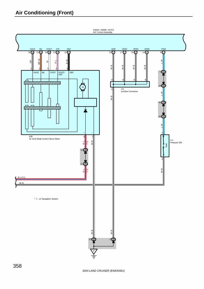
2004 LAND CRUISER (EWD548U)
358
Air Conditioning (Front)
R- L(*1)
W- B
M
FACE B/L FOOT FOOT/DEF
DEF
-+
A16
FACE
A15
B/L
A14
FOOT
A13
F/D
A12
DEF
GR
BR
-W W P-L
B-W
1 2 3 4 5
IF
2D23
76
3N22
3N11
R-L
R-L
W-B
( *1)
W-B
A26
A
C12
GND
2D2
A
W-B
W-B
W-B
A
C17
VER2
W-B
A
C15
VER4
W-B
A
C14
VER5
W-B
J11
C8
PSW
5A5
5D18
1B46
1A46
1
4
Dua
l
A 4
L-W
L-W
L-W
W-B
A45(A), A46(B), A47(C)
Pressure SW
Air Vent Mode Control Servo Motor
A/C Control Assembly
Junction Connector
* 1 : w/ Navigation System
( *1)

2004 LAND CRUISER (EWD548U)
359
PT
Coo
lW
arm
M
GND
B-Y
Y-G
G-R
P-BP
VZHMOTMCOOL
B7
TAM
1
2
1A25
1B31
Y-G
B17
FRTR
BB
1
2
Y-G
5D22 5B13 5B16
5B14
Y-G
Y-G
Y-G
B18
FRSG
A 1
R 7
A22
FRAMC
A21
FRAMH
B5
FRTP
3N
G- R
4
Y-G
P-G P-B
B-Y
Y- G
32 5 4 6
A25
3N3
3N2
G-R
A45(A), A46(B), A47(C)
3N1
B16
FRTE
GR
-BG
R-B
1
2
Y-G
A19
Y- G
5B12
5D23
1B32
1A13
L-Y
L-Y
L-Y
A/C
Am
bien
t Tem
p.
Sen
sor
A/C
The
rmis
tor
Air Mix Control Servo Motor
Roo
m T
emp.
S
enso
r ( F
ront
)
A/C Control Assembly

2004 LAND CRUISER (EWD548U)
360
Air Conditioning (Front)
13 3N
A45(A), A46(B), A47(C)
B14
TPI
3N8
3N19
L-R
L-R
A1
AIF AIR
2 A
3N15
G-W
LG-B
3 4 5
1 2
Y-G
G-R
A24
B8
TS
3D28
3Q83
B-Y
1
2
3Q81
3E30
7 3P 3N5
A18
B9
FRS5
SB
G-R
G-R
G-R
SB
C1
TAMO2
4A16
4E1
P-L
A19
MPX+
4A10
4E6
B
A39
MPX-
4C3
4E4
P-B
4 11
5 12
B P-B
P-L
P-B
P-L
G 4
( *2)
M 6(A), M 9(B)
( *1)
( *1)
( *1)
( *1)
( *1)
( *1)
( *2)
GTX-
A/CTEMP
TX3+ TX3-
GTX+
MPD1 MPD2
C6
SPD
V
A10
RDFGR
LG
A6
MRRHR
R
A40
RRMGV
LG-R
Com
bina
tion
Met
er
DE
FOG
Rel
ay
MIR
HTR
Rel
ay
Rea
r C
oole
r M
agne
tic V
alve
A/C
Sol
ar S
enso
r
Air
Inle
t C
ontr
ol S
ervo
Mot
or
Gat
eway
EC
U
Multi- Display
A/C Control Assembly
VZGND
PT MFRS MREC
M
B16 A11 A12
Ic25 Ic24
P-L
P-B( *1)
( *1)
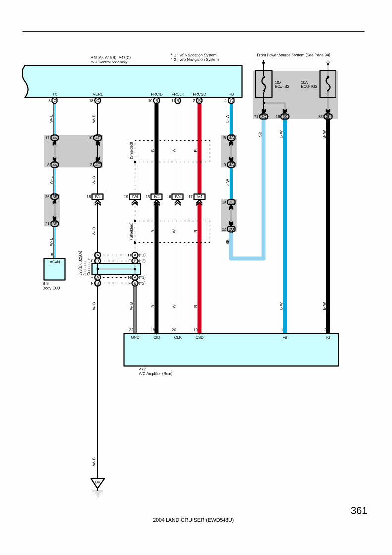
2004 LAND CRUISER (EWD548U)
361
C11
+B
10AECU- B2
3Q71 3K19
18 4A
4A9
19 2E
2Q22L-
WL-
WS
B
L-W
SB
4A17
4A8
3E26
3E21
W-L
W-L
W-L
R
A45(A), A46(B), A47(C)
TC
3 C
5
ACAN
B 9
4F10
4C2
W-B
W-B
VER1
18 C
IV418 IV419 IV415 IV416
B10
FRCID FRCLK
1 B
IV417
FRCSD
2 B
BK
GND CID CLK CSD +B IG
B W R
( Shi
elde
d)
WB
B-W
B-W
L-W
W-B
10AECU- IG2
From Power Source System (See Page 94)
3K35
B W R
W-B
W-B
W-B
A32
( Shi
elde
d)
* 2 : w/o Navigation System* 1 : w/ Navigation System
A/C Amplifier (Rear)
A/C Control Assembly
Body ECU
2119201822
BF
AH
BF (*2)AH (*1)
AH (*1)
BF (*2)AH
BF
Junc
tion
Con
nect
or
J23(
B) ,
J25
( A)

2004 LAND CRUISER (EWD548U)
362
Air Conditioning (Front)
1. Heater Blower OperationManual operationWhen the blower speed is set ant any speed by the blower control SW, the A/C control assembly sends a signal to theblower motor controller, and controls the blower motor speed.Auto operationWhen the auto SW is operated, the A/C control assembly sends signals to the blower motor controller, according to thesignals from respective sensors, commands from the temperature SW etc., and controls the blower motor automatically.
2. Air Inlet Control Servo Motor ControlWhen the FRESH/RECIRC select SW is switched to RECIRC, the motor in the air inlet control servo motor rotates to movethe damper to the RECIRC side. The damper position is recognized by the A/C control assembly TERMINAL TPI, androtates the motor until the damper reaches its position.When the FRESH/RECIRC select SW is switched to FRESH, the motor in the air inlet control servo motor rotates to movethe damper to the FRESH side. The damper position is recognized by the A/C control assembly TERMINAL TPI, and rotatesthe motor until the damper reaches its position.When the FRESH/RECIRC select SW is set to auto, the exhaust gas sensor in the engine room detects the ingredient of theexhaust emission, and switches the FRESH/RECIRC mode automatically.
3. Air Vent Mode Control Servo MotorWhen the mode select SW in the A/C control assembly is pushed, a signal is sent from the A/C control assembly, andactivates the air vent mode control servo motor. This causes the servo motor to rotate to the position selected using themode select SW (FACE, BI-LEVEL, FOOT, FOOT/DEF, DEF), and moves the damper.
4. Air Mix Control Servo MotorWhen the temperature control SW in the A/C control assembly is pushed, a signal is sent from the A/C control assembly, andactivates the air mix control servo motor. The motor and damper is moved until it reaches the temperature set by thetemperature control SW.
5. Air Conditioning OperationThe A/C control assembly receives various signals, i. e., the engine RPM from the crankshaft position sensor, outlettemperature from the A/C ambient temp. sensor, coolant temperature from the engine coolant temp. sensor, and the locksignal from the A/C compressor, etc. When the engine is started and the A/C SW is turned on, a signal is sent to the A/Ccontrol assembly. As a result, the magnetic clutch is turned on and operates the compressor.In addition, when the engine control module detects that the magnetic clutch is on and the A/C compressor is operating, itcontrols the engine in the direction to avoid lowering the engine RPM during A/C operation.When any of the following signals are sent to the A/C control assembly, the A/C is turned off.∗ Coolant temp. is high.∗ Outlet air temp. is low.∗ Large difference between the engine speed and compressor speed.∗ The refrigerant pressure is abnormally high or low.
A45 (A), A47 (C) A/C Control Assembly(C)11-Ground : Always approx. 12 volts(C)22-Ground : Approx. 12 volts with ignition SW at ON or ST position(A)27-Ground : Approx. 12 volts with ignition SW at ON or ST position (w/o navigation system)(C)12, (C) 14, (C) 15, (C) 17, (C) 18-Ground : Always continuity
C28 Center Cluster Integration Panel (w/ Navigation System)2-Ground : Approx. 12 volts with ignition SW at ON or ST position
16-Ground : Always continuity
System Outline
Service Hints
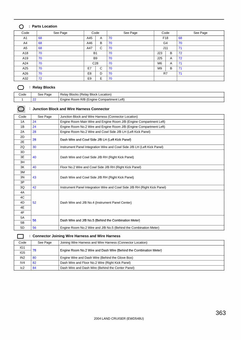
2004 LAND CRUISER (EWD548U)
363
: Parts Location
Code See Page Code See Page Code See Page
A1 68 A45 A 70 F18 68
A4 68 A46 B 70 G4 70
A5 68 A47 C 70 J11 71
A18 70 B1 70 J23 B 72
A19 70 B9 70 J25 A 72
A24 70 C28 70 M6 A 71
A25 70 E7 C 70 M9 B 71
A26 70 E8 D 70 R7 71
A32 72 E9 E 70
: Relay Blocks
Code See Page Relay Blocks (Relay Block Location)
1 22 Engine Room R/B (Engine Compartment Left)
: Junction Block and Wire Harness Connector
Code See Page Junction Block and Wire Harness (Connector Location)
1A 24 Engine Room Main Wire and Engine Room J/B (Engine Compartment Left)
1B 24 Engine Room No.2 Wire and Engine Room J/B (Engine Compartment Left)
2A 28 Engine Room No.2 Wire and Cowl Side J/B LH (Left Kick Panel)
2D28 Dash Wire and Cowl Side J/B LH (Left Kick Panel)
2E28 Dash Wire and Cowl Side J/B LH (Left Kick Panel)
2Q 30 Instrument Panel Integration Wire and Cowl Side J/B LH (Left Kick Panel)
3D
3E 40 Dash Wire and Cowl Side J/B RH (Right Kick Panel)
3H
( g )
3K 40 Floor No.2 Wire and Cowl Side J/B RH (Right Kick Panel)
3M
3N 43 Dash Wire and Cowl Side J/B RH (Right Kick Panel)
3P
( g )
3Q 42 Instrument Panel Integration Wire and Cowl Side J/B RH (Right Kick Panel)
4A
4C
4D 52 Dash Wire and J/B No.4 (Instrument Panel Center)
4E
( )
4F
5A56 Dash Wire and J/B No 5 (Behind the Combination Meter)
5B56 Dash Wire and J/B No.5 (Behind the Combination Meter)
5D 56 Engine Room No.2 Wire and J/B No.5 (Behind the Combination Meter)
: Connector Joining Wire Harness and Wire Harness
Code See Page Joining Wire Harness and Wire Harness (Connector Location)
IG178 Engine Room No 2 Wire and Dash Wire (Behind the Combination Meter)
IG578 Engine Room No.2 Wire and Dash Wire (Behind the Combination Meter)
IN2 80 Engine Wire and Dash Wire (Behind the Glove Box)
IV4 82 Dash Wire and Floor No.2 Wire (Right Kick Panel)
Ic2 84 Dash Wire and Dash Wire (Behind the Center Panel)

2004 LAND CRUISER (EWD548U)
364
Air Conditioning (Front)
: Ground Points
Code See Page Ground Points Location
EA 76 Front Right Side of Fender Apron
EC 76 Rear Bank of Right Cylinder Head
IF 78 Set Bolt of Cowl Side J/B LH
II 78 Set Bolt of Cowl Side J/B RH
BK 86 Front Side Under the Front Passenger’s Seat
: Splice Points
Code See Page Wire Harness with Splice Points Code See Page Wire Harness with Splice Points
E16 76 Engine Room No.2 Wire

2004 LAND CRUISER (EWD548U)
365
Memo

2004 LAND CRUISER (EWD548U)
366
Air Conditioning (Rear)
A45(A), A46(B), A47(C)
C12
GND
IF
A
A
VER2
17 C
A
VER4
15 C
A
VER5
14 C
A
W-B
W-B
W-B
W-B
J11
2D2
W-B
W-B
A40
RRMGV
IV422
LG-R
LG-R
BW12
140A
ALT
120A
J/B
NO
. 2
F16
B-G
2C1
7. 5AAM1
2E39
B-R
2 4AM1
ACC
IG1
2E37L-
B
2B3
LG- R
LG-R
L-B
L- B
I18
Battery
1
Ignition SW
A/C Control Assembly
Junction Connector
FusibleLink Block
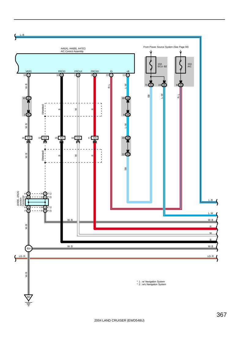
2004 LAND CRUISER (EWD548U)
367
C18
VER1
4F10
4C2
IV418
W-B
W-B
IV419 IV415 IV416 IV417
B10
FRCID
B1
FRCLK
B2
FRCSD
( Shi
elde
d)
B W R
10AECU- B2
From Power Source System (See Page 94)
3Q71 3K19
C11
+B
L-W
L-W
9 4A
18 4A
2E19
2Q22
SB
C22
IG
15AA/C
2D6
R-L
R-L
W-B
B14
W-B
LG- R
BK
A45(A), A46(B), A47(C)
L- B
L- B
L- W
W- B
R
W
B
W- B
LG- R
W- B
L-W
W- B
W-B
SB
A/C Control Assembly
RWB
( Shi
elde
d)
Junc
tion
Con
nect
or
J23(
B) ,
J25(
A)
BF (*2)AH (*1)
BFAH
AHBF
AH (*1)
BF (*2)
* 2 : w/o Navigation System* 1 : w/ Navigation System

2004 LAND CRUISER (EWD548U)
368
Air Conditioning (Rear)
3K
A14
HRRH
18
3B10
1B71 1B52
50 1B
10ARRHTR
From Power Source System(See Page 94)
L-B
L-B
F
L
IA218
2
1
L- B
L- W
W- B
R
W
B
W- B
LG- R
L-B
L-B
L
L
BJ
3 2
1
A16
BLWRH
A15
VMRH
BL41 BL42
BD319 18 BD3
R-W
R-G
R-W
R-G
R-W
R-G
W-B
W-B
R25
L- W
W- B
R
W
B
W- B
LG- R
R22
RR HTRRelay
A32(A), A33(B), A34(C)A/C Amplifier (Rear)
Rear HeaterBlower Motor
Rea
r H
eate
r P
ower
Tra
nsis
tor
4
F
L- B
JunctionConnector
J22
M
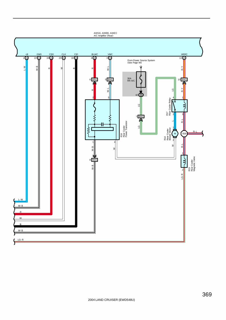
2004 LAND CRUISER (EWD548U)
369
A18
CIDCLK
20 A
CSD
19 AA22
GND+B
1 A
BW16
A4
BLWC
2 3
1 4
BW18
W-B
W-B
RR
BW15
A3
VMC
W-L
W-L
R16
BW110
A13
HRRC
R-Y
R-Y
2 3
4 1
2
1
L
R-L
B19
R14
R17
30ARR A/C
From Power Source System(See Page 94)
3K42
BW17
LG
LG
LG
R- L
2
1
LG-R
R-LW
W
LG- R
W- B
B
W
R
W- B
L- W
A32(A), A33(B), A34(C)
L-W
W-B R W B
R15
A/C Amplifier (Rear)
Rea
r C
oole
rB
low
er M
otor
Rea
r C
oole
rM
agne
tic V
alve
Rea
r C
oole
rP
ower
Tra
nsis
tor
Rea
r C
oole
r R
elay
M
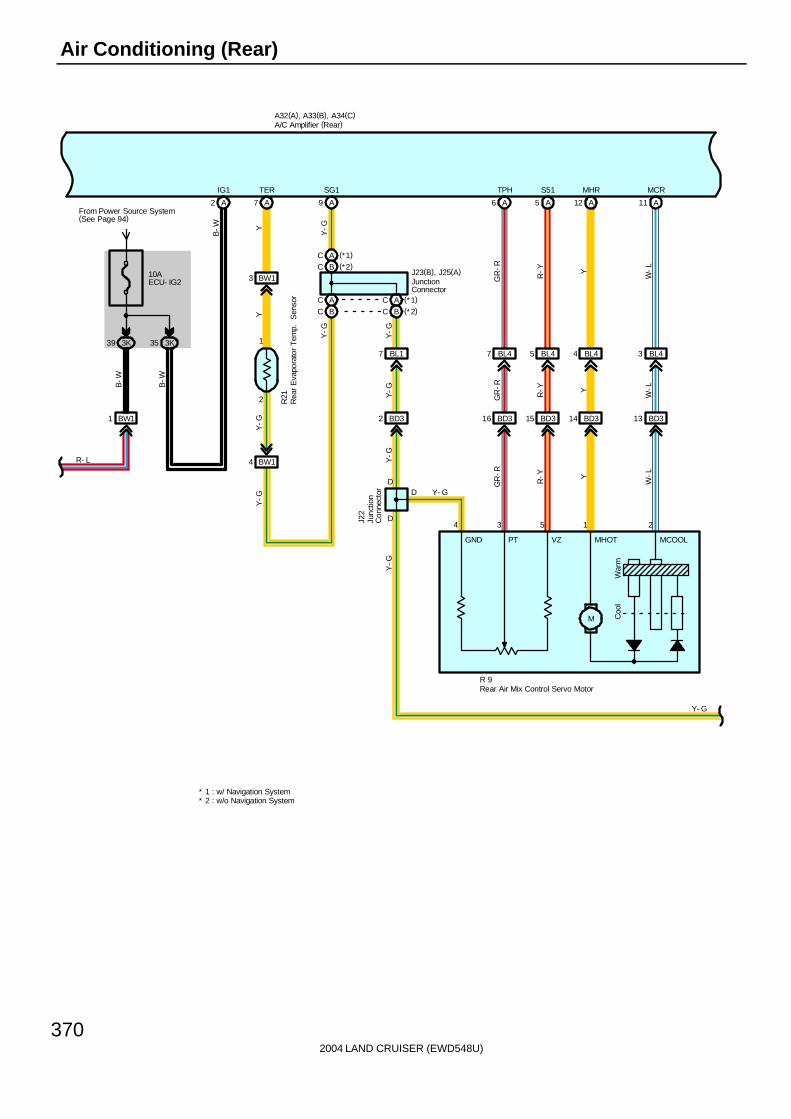
2004 LAND CRUISER (EWD548U)
370
Air Conditioning (Rear)
M Coo
lW
arm
GND PT VZ MHOT MCOOL
3K39
BW11
B-W
10AECU- IG2
3K35
From Power Source System(See Page 94)
R- L
B-W
BW13
A7
TER
YY
2
1
BW14
Y-G
R21
A9
SG1
BL17
BD32
B-W
Y- G
Y-G
BL47
BD316
GR
-R
BL45
BD315
R-Y
BL44
BD314
Y
BL43
BD313
W-L
A6
TPH
A5
S51
A12
MHR
A11
MCR
3 5 1 2
R 9
2
GR
-R
R-Y Y
W-L
GR
-R
R-Y Y
W-L
Y-G
Y-G
D
D
D
A
Y-G
Y-G
Y-G
Y-G
IG1
Y- G
A32(A), A33(B), A34(C)
J22
4
A/C Amplifier (Rear)
Rear Air Mix Control Servo Motor
Rea
r E
vapo
rato
r T
emp.
S
enso
r
Junc
tion
Con
nect
or
JunctionConnector
J23(B), J25(A)(*2)(*1)
BCAC
AC (*1)
BC (*2)ACBC
* 2 : w/o Navigation System* 1 : w/ Navigation System

2004 LAND CRUISER (EWD548U)
371
1
2
BL46
BD317
GR
-G
A8
TINR
GR
-GG
R-G
Y-G
R26
Y- G
LO- IAUTO- I ME- I HI- I FACE- I
Hot
FOOT- I
Cool
AU
TO
Foot
LO
Mid
dle
HI
Face
Bi-
Leve
l
B/L- IS5T- SETSG
B12
SG2
2
1
B7
TRR
B13
B8
TESTR
20 21
BG
-Y
G-Y
L-O
G-Y
L-O
B4
S52
22
Y-R
Y-R
C5
AUTO- I
7
L-R
L-R
C6
LO- I
6
L-W
L-W
C7
ME- I
5
LL
C18
HI- I
4
LL
C15
FACE- I
3
GG
C16
B/L- I
2
W-G
W-G
C17
FOOT- I
1
W-R
W-R
A32(A), A33(B), A34(C)
R 8
R34
A/C Amplifier (Rear)
Rear A/C Control SW
Rea
r In
let A
ir T
emp.
S
enso
r
Roo
m T
emp.
S
enso
r ( R
ear)

2004 LAND CRUISER (EWD548U)
372
Air Conditioning (Rear)
Illum
inat
ion
AU
TO
OFFLO
Mid
dle
HI
Fac
e
Bi-
Leve
l
Foot
IG RG SRG FOOT- S B/L- S FACE- S HI- S ME- S LO- S OFF- S AUTO- SILL
B13
B1
IG2
9
L-R
L-R
B5
ILL+2
8
GG
C8
10
RG
G-W
C12
FOOT- S
12
R-G
R-G
C11
B/L- S
13
R-Y
R-Y
C10
FACE- S
14
R-L
R-L
C9
HI- S
15
GR
-RG
R-R
C4
ME- S
16
L-Y
L-Y
C3
LO- S
17
GR
GR
C2
OFF- S
18
Y-B
Y-B
C1
AUTO- S
19
W-G
W-G
G-W
G-W
A32(A), A33(B), A34(C)
R 8
11
A/C Amplifier (Rear)
Rear A/C Control SW

2004 LAND CRUISER (EWD548U)
373
1. Cooler and Heater Blower Operation∗ Manual operation
When the blower control SW in the rear A/C control SW is set to any blower speed, a signal is sent to the A/C amplifier.The A/C amplifier controls the power transistor and operates the rear cooler blower motor and rear heater blower motor atthe set speed.
∗ Auto operationWhen the auto SW in the rear A/C control SW is operated, a signal is sent to the A/C amplifier. The A/C amplifier controlsthe power transistor according to the signals from respective sensors, and operates the rear cooler blower motor and rearheater blower motor.
2. Air Mix Control Servo Motor ControlWhen the temperature control lever in the rear A/C control SW is operated, a signal is sent to the A/C amplifier. The A/Camplifier controls the rear air mix control servo motor to operate the damper until it reaches the temperature set by thetemperature control lever.
3. Air Conditioning OperationThe cooler and heater operation can be switched by the mode select SW in the rear A/C control SW.
A32 A/C Amplifier (Rear)1-Ground : Always approx. 12 volts2-Ground : Approx. 12 volts with ignition SW at ON or ST position
22-Ground : Always continuity
: Parts Location
Code See Page Code See Page Code See Page
A32 A 72 J11 71 R16 73
A33 B 72 J22 72 R17 73
A34 C 72 J23 B 72 R21 73
A45 A 70 J25 A 72 R22 73
A46 B 70 R8 73 R25 73
A47 C 70 R9 73 R26 73
F16 68 R14 73 R34 73
I18 70 R15 73
: Junction Block and Wire Harness Connector
Code See Page Junction Block and Wire Harness (Connector Location)
1B 24 Engine Room No.2 Wire and Engine Room J/B (Engine Compartment Left)
2B28 Engine Room No 2 Wire and Cowl Side J/B LH (Left Kick Panel)
2C28 Engine Room No.2 Wire and Cowl Side J/B LH (Left Kick Panel)
2D28 Dash Wire and Cowl Side J/B LH (Left Kick Panel)
2E28 Dash Wire and Cowl Side J/B LH (Left Kick Panel)
2Q 30 Instrument Panel Integration Wire and Cowl Side J/B LH (Left Kick Panel)
3B 40 Engine Room No.2 Wire and Cowl Side J/B RH (Right Kick Panel)
3K 40 Floor No.2 Wire and Cowl Side J/B RH (Right Kick Panel)
3Q 42 Instrument Panel Integration Wire and Cowl Side J/B RH (Right Kick Panel)
4A
4C 52 Dash Wire and J/B No.4 (Instrument Panel Center)
4F
( )
System Outline
Service Hints
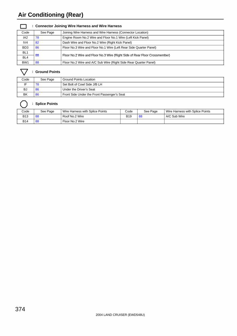
2004 LAND CRUISER (EWD548U)
374
Air Conditioning (Rear)
: Connector Joining Wire Harness and Wire Harness
Code See Page Joining Wire Harness and Wire Harness (Connector Location)
IA2 78 Engine Room No.2 Wire and Floor No.1 Wire (Left Kick Panel)
IV4 82 Dash Wire and Floor No.2 Wire (Right Kick Panel)
BD3 86 Floor No.3 Wire and Floor No.1 Wire (Left Rear Side Quarter Panel)
BL188 Floor No 2 Wire and Floor No 3 Wire (Right Side of Rear Floor Crossmember)
BL488 Floor No.2 Wire and Floor No.3 Wire (Right Side of Rear Floor Crossmember)
BW1 88 Floor No.2 Wire and A/C Sub Wire (Right Side Rear Quarter Panel)
: Ground Points
Code See Page Ground Points Location
IF 78 Set Bolt of Cowl Side J/B LH
BJ 86 Under the Driver’s Seat
BK 86 Front Side Under the Front Passenger’s Seat
: Splice Points
Code See Page Wire Harness with Splice Points Code See Page Wire Harness with Splice Points
B13 88 Roof No.2 Wire B19 88 A/C Sub Wire
B14 88 Floor No.2 Wire

2004 LAND CRUISER (EWD548U)
375
Memo

2004 LAND CRUISER (EWD548U)
93
SYSTEM CIRCUITS H
2004 LAND CRUISERELECTRICAL WIRING DIAGRAM
SYSTEM CIRCUITSPage
Air Conditioning (Front) . . . . . . . . . . . . . . . . . . . . . . . . . . . . . . . . . . . . . . . . . . . . . . 356Air Conditioning (Rear) . . . . . . . . . . . . . . . . . . . . . . . . . . . . . . . . . . . . . . . . . . . . . . 366Auto Antenna . . . . . . . . . . . . . . . . . . . . . . . . . . . . . . . . . . . . . . . . . . . . . . . . . . . . . . . 322Automatic Glare-Resistant EC Mirror with Compass . . . . . . . . . . . . . . . . . . . 304Automatic Light Control . . . . . . . . . . . . . . . . . . . . . . . . . . . . . . . . . . . . . . . . . . . . . 164Back-Up Light . . . . . . . . . . . . . . . . . . . . . . . . . . . . . . . . . . . . . . . . . . . . . . . . . . . . . . 162Center Differential Lock . . . . . . . . . . . . . . . . . . . . . . . . . . . . . . . . . . . . . . . . . . . . . . 246Charging . . . . . . . . . . . . . . . . . . . . . . . . . . . . . . . . . . . . . . . . . . . . . . . . . . . . . . . . . . . 104Cigarette Lighter . . . . . . . . . . . . . . . . . . . . . . . . . . . . . . . . . . . . . . . . . . . . . . . . . . . . 204Combination Meter . . . . . . . . . . . . . . . . . . . . . . . . . . . . . . . . . . . . . . . . . . . . . . . . . . 350Cruise Control . . . . . . . . . . . . . . . . . . . . . . . . . . . . . . . . . . . . . . . . . . . . . . . . . . . . . . 222Door Lock Control . . . . . . . . . . . . . . . . . . . . . . . . . . . . . . . . . . . . . . . . . . . . . . . . . . . 260Electronically Controlled Transmission and A/T Indicator . . . . . . . . . . . . . . . 212Engine Control . . . . . . . . . . . . . . . . . . . . . . . . . . . . . . . . . . . . . . . . . . . . . . . . . . . . . . 108Engine Immobiliser System . . . . . . . . . . . . . . . . . . . . . . . . . . . . . . . . . . . . . . . . . . 124Front Fog Light . . . . . . . . . . . . . . . . . . . . . . . . . . . . . . . . . . . . . . . . . . . . . . . . . . . . . 132Front Wiper and Washer . . . . . . . . . . . . . . . . . . . . . . . . . . . . . . . . . . . . . . . . . . . . . 196Garage Door Opener . . . . . . . . . . . . . . . . . . . . . . . . . . . . . . . . . . . . . . . . . . . . . . . . 210Headlight . . . . . . . . . . . . . . . . . . . . . . . . . . . . . . . . . . . . . . . . . . . . . . . . . . . . . . . . . . . 128Horn . . . . . . . . . . . . . . . . . . . . . . . . . . . . . . . . . . . . . . . . . . . . . . . . . . . . . . . . . . . . . . . 208Ignition . . . . . . . . . . . . . . . . . . . . . . . . . . . . . . . . . . . . . . . . . . . . . . . . . . . . . . . . . . . . . 100Illumination . . . . . . . . . . . . . . . . . . . . . . . . . . . . . . . . . . . . . . . . . . . . . . . . . . . . . . . . . 142Interior Light . . . . . . . . . . . . . . . . . . . . . . . . . . . . . . . . . . . . . . . . . . . . . . . . . . . . . . . . 148Key Reminder . . . . . . . . . . . . . . . . . . . . . . . . . . . . . . . . . . . . . . . . . . . . . . . . . . . . . . . 316Light Auto Turn Off . . . . . . . . . . . . . . . . . . . . . . . . . . . . . . . . . . . . . . . . . . . . . . . . . . 166Mirror Heater . . . . . . . . . . . . . . . . . . . . . . . . . . . . . . . . . . . . . . . . . . . . . . . . . . . . . . . . 314Moon Roof . . . . . . . . . . . . . . . . . . . . . . . . . . . . . . . . . . . . . . . . . . . . . . . . . . . . . . . . . 256Multi-Display (w/o Navigation System) . . . . . . . . . . . . . . . . . . . . . . . . . . . . . . . . 348Multiplex Communication System . . . . . . . . . . . . . . . . . . . . . . . . . . . . . . . . . . . . 172Multiplex Communication System (Communication Bus) . . . . . . . . . . . . . . . 168Navigation System . . . . . . . . . . . . . . . . . . . . . . . . . . . . . . . . . . . . . . . . . . . . . . . . . . 336Power Outlet . . . . . . . . . . . . . . . . . . . . . . . . . . . . . . . . . . . . . . . . . . . . . . . . . . . . . . . . 206Power Rear Quarter Window . . . . . . . . . . . . . . . . . . . . . . . . . . . . . . . . . . . . . . . . . 306Power Seat . . . . . . . . . . . . . . . . . . . . . . . . . . . . . . . . . . . . . . . . . . . . . . . . . . . . . . . . . 294Power Source . . . . . . . . . . . . . . . . . . . . . . . . . . . . . . . . . . . . . . . . . . . . . . . . . . . . . . . 94Power Tilt and Power Telescopic . . . . . . . . . . . . . . . . . . . . . . . . . . . . . . . . . . . . . 298Power Window . . . . . . . . . . . . . . . . . . . . . . . . . . . . . . . . . . . . . . . . . . . . . . . . . . . . . . 250Radio and Player (w/ Navigation System) . . . . . . . . . . . . . . . . . . . . . . . . . . . . . . 324Radio and Player (w/o Navigation System) . . . . . . . . . . . . . . . . . . . . . . . . . . . . . 330Rear Window Defogger . . . . . . . . . . . . . . . . . . . . . . . . . . . . . . . . . . . . . . . . . . . . . . 312Rear Wiper and Washer . . . . . . . . . . . . . . . . . . . . . . . . . . . . . . . . . . . . . . . . . . . . . . 200Remote Control Mirror . . . . . . . . . . . . . . . . . . . . . . . . . . . . . . . . . . . . . . . . . . . . . . . 302Seat Belt Warning . . . . . . . . . . . . . . . . . . . . . . . . . . . . . . . . . . . . . . . . . . . . . . . . . . . 320Seat Heater . . . . . . . . . . . . . . . . . . . . . . . . . . . . . . . . . . . . . . . . . . . . . . . . . . . . . . . . . 308Shift Lock . . . . . . . . . . . . . . . . . . . . . . . . . . . . . . . . . . . . . . . . . . . . . . . . . . . . . . . . . . 244SRS . . . . . . . . . . . . . . . . . . . . . . . . . . . . . . . . . . . . . . . . . . . . . . . . . . . . . . . . . . . . . . . . 237Starting . . . . . . . . . . . . . . . . . . . . . . . . . . . . . . . . . . . . . . . . . . . . . . . . . . . . . . . . . . . . 98Stop Light . . . . . . . . . . . . . . . . . . . . . . . . . . . . . . . . . . . . . . . . . . . . . . . . . . . . . . . . . . 156Taillight . . . . . . . . . . . . . . . . . . . . . . . . . . . . . . . . . . . . . . . . . . . . . . . . . . . . . . . . . . . . 138Theft Deterrent . . . . . . . . . . . . . . . . . . . . . . . . . . . . . . . . . . . . . . . . . . . . . . . . . . . . . . 282TOYOTA Parking Assist (Rear View Monitor) . . . . . . . . . . . . . . . . . . . . . . . . . . . 336Trailer Towing . . . . . . . . . . . . . . . . . . . . . . . . . . . . . . . . . . . . . . . . . . . . . . . . . . . . . . . 158Turn Signal and Hazard Warning Light . . . . . . . . . . . . . . . . . . . . . . . . . . . . . . . . 134VSC . . . . . . . . . . . . . . . . . . . . . . . . . . . . . . . . . . . . . . . . . . . . . . . . . . . . . . . . . . . . . . . . 228Wireless Door Lock Control . . . . . . . . . . . . . . . . . . . . . . . . . . . . . . . . . . . . . . . . . . 270
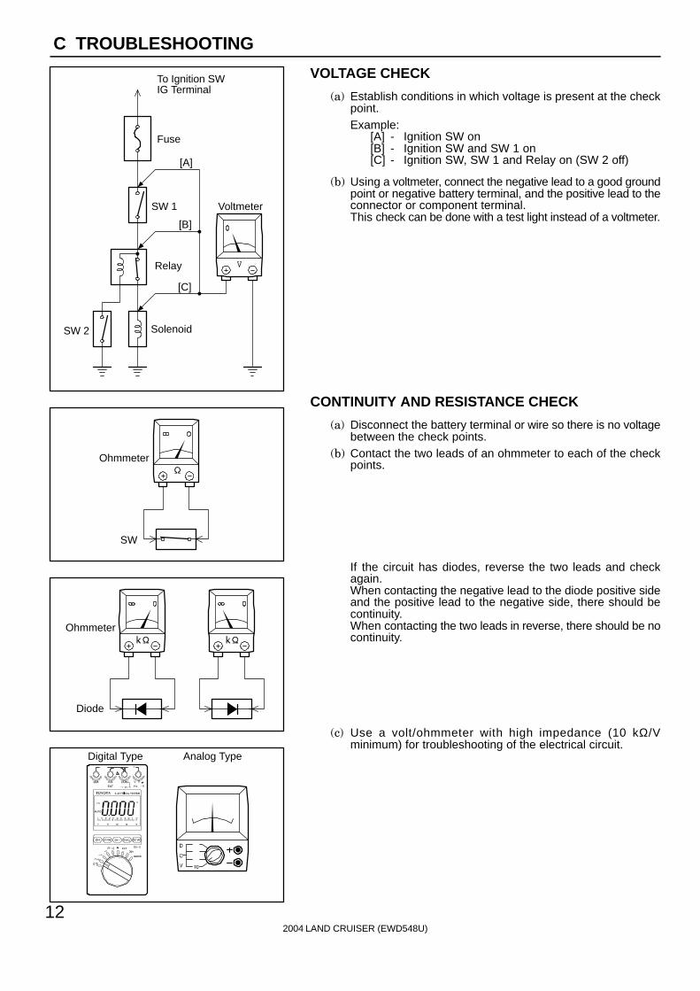
To Ignition SWIG Terminal
Fuse
VoltmeterSW 1
Relay
SW 2 Solenoid
[A]
[B]
[C]
Ohmmeter
SW
Ohmmeter
Diode
Digital Type Analog Type
2004 LAND CRUISER (EWD548U)
12
C TROUBLESHOOTING
VOLTAGE CHECK
(a) Establish conditions in which voltage is present at the checkpoint.Example:
[A] - Ignition SW on[B] - Ignition SW and SW 1 on[C] - Ignition SW, SW 1 and Relay on (SW 2 off)
(b) Using a voltmeter, connect the negative lead to a good groundpoint or negative battery terminal, and the positive lead to theconnector or component terminal.This check can be done with a test light instead of a voltmeter.
CONTINUITY AND RESISTANCE CHECK
(a) Disconnect the battery terminal or wire so there is no voltagebetween the check points.
(b) Contact the two leads of an ohmmeter to each of the checkpoints.
If the circuit has diodes, reverse the two leads and checkagain.When contacting the negative lead to the diode positive sideand the positive lead to the negative side, there should becontinuity.When contacting the two leads in reverse, there should be nocontinuity.
(c) Use a volt/ohmmeter with high impedance (10 kΩ/Vminimum) for troubleshooting of the electrical circuit.
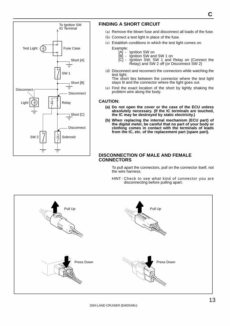
To Ignition SWIG Terminal
Test Light
RelayLight
SW 2 Solenoid
Disconnect
Short [A]
DisconnectDisconnect
SW 1
Fuse Case
Short [B]
Short [C]
Pull Up
Press Down Press Down
Pull Up
2004 LAND CRUISER (EWD548U)
13
C
FINDING A SHORT CIRCUIT
(a) Remove the blown fuse and disconnect all loads of the fuse.(b) Connect a test light in place of the fuse.(c) Establish conditions in which the test light comes on.
Example:[A] - Ignition SW on[B] - Ignition SW and SW 1 on[C] - Ignition SW, SW 1 and Relay on (Connect the
Relay) and SW 2 off (or Disconnect SW 2)
(d) Disconnect and reconnect the connectors while watching thetest light.The short lies between the connector where the test lightstays lit and the connector where the light goes out.
(e) Find the exact location of the short by lightly shaking theproblem wire along the body.
CAUTION:(a) Do not open the cover or the case of the ECU unless
absolutely necessary. (If the IC terminals are touched,the IC may be destroyed by static electricity.)
(b) When replacing the internal mechanism (ECU part) ofthe digital meter, be careful that no part of your body orclothing comes in contact with the terminals of leadsfrom the IC, etc. of the replacement part (spare part).
DISCONNECTION OF MALE AND FEMALECONNECTORS
To pull apart the connectors, pull on the connector itself, notthe wire harness.
HINT : Check to see what kind of connector you aredisconnecting before pulling apart.

10
3
0.21
1
(mm)
Reference:
ToolUpExample:(Case 1)
Terminal Retainer
Terminal Retainer
[Retainer at Full Lock Position]
[Retainer at Temporary Lock Position]
StopperTerminalRetainer
SecondaryLocking Device
Example:(Case 2)
2004 LAND CRUISER (EWD548U)
14
C TROUBLESHOOTING
HOW TO REPLACE TERMINAL(with terminal retainer or secondary locking device)
1. PREPARE THE SPECIAL TOOL
HINT : To remove the terminal from the connector, pleaseconstruct and use the special tool or like object shown onthe left.
2. DISCONNECT CONNECTOR
3. DISENGAGE THE SECONDARY LOCKING DEVICE OR
TERMINAL RETAINER.
(a) Locking device must be disengaged before the terminallocking clip can be released and the terminal removed fromthe connector.
(b) Use a special tool or the terminal pick to unlock the secondarylocking device or terminal retainer.
NOTICE:Do not remove the terminal retainer from connector body.
[A] For Non-Waterproof Type Connector
HINT : The needle insertion position varies according to the
connector’s shape (number of terminals etc.), so
check the position before inserting it.
”Case 1”
Raise the terminal retainer up to the temporary lock
position.
”Case 2”
Open the secondary locking device.

ToolTab
Tab
TerminalRetainer
Access Hole( Mark)
Tool
Tool
[Female]
Example:
[Male]
(Case 1)
[Male] [Female]
Retainerat Full Lock Position
Retainerat Temporary Lock Position
Terminal Retainer
[Male] Press Down [Female]Press Down
ToolTool
Example:(Case 2)
2004 LAND CRUISER (EWD548U)
15
C
[B] For Waterproof Type Connector
HINT : Terminal retainer color is differentaccording to connector body.
Example:Terminal Retainer : Connector BodyBlack or White : GrayBlack or White : Dark GrayGray or White : Black
”Case 1”Type where terminal retainer is pulledup to the temporary lock position (PullType).
Insert the special tool into the terminalretainer access hole (Mark) and pullthe terminal retainer up to thetemporary lock position.
HINT : The needle insertion position variesaccording to the connector’s shape(Number of terminals etc.), so checkthe position before inserting it.
”Case 2”Type which cannot be pulled as far asPower Lock insert the tool straight intothe access hole of terminal retainer asshown.

Retainer atFull Lock Position
[Male] [Female]
Retainer atTemporary Lock Position
Locking Lug
Tool
2004 LAND CRUISER (EWD548U)
16
C TROUBLESHOOTING
Push the terminal retainer down to the temporary lock position.
(c) Release the locking lug from terminal and pull the terminal outfrom rear.
4. INSTALL TERMINAL TO CONNECTOR
(a) Insert the terminal.HINT:1. Make sure the terminal is positioned correctly.2. Insert the terminal until the locking lug locks firmly.3. Insert the terminal with terminal retainer in the temporary lock
position.
(b) Push the secondary locking device or terminal retainer in tothe full lock position.
5. CONNECT CONNECTOR